WO2022219790A1 - Charged particle beam apparatus - Google Patents
Charged particle beam apparatus Download PDFInfo
- Publication number
- WO2022219790A1 WO2022219790A1 PCT/JP2021/015638 JP2021015638W WO2022219790A1 WO 2022219790 A1 WO2022219790 A1 WO 2022219790A1 JP 2021015638 W JP2021015638 W JP 2021015638W WO 2022219790 A1 WO2022219790 A1 WO 2022219790A1
- Authority
- WO
- WIPO (PCT)
- Prior art keywords
- charged particle
- particle beam
- shield
- bushing
- beam device
- Prior art date
Links
- 239000002245 particle Substances 0.000 title claims abstract description 94
- 230000001133 acceleration Effects 0.000 claims abstract description 26
- 239000002184 metal Substances 0.000 claims abstract description 16
- 229910052751 metal Inorganic materials 0.000 claims abstract description 16
- 238000000034 method Methods 0.000 claims abstract description 5
- 239000011248 coating agent Substances 0.000 claims description 5
- 238000000576 coating method Methods 0.000 claims description 5
- 238000010894 electron beam technology Methods 0.000 description 48
- 239000007789 gas Substances 0.000 description 11
- 238000009413 insulation Methods 0.000 description 11
- 230000015556 catabolic process Effects 0.000 description 8
- 230000005684 electric field Effects 0.000 description 7
- 238000001514 detection method Methods 0.000 description 5
- 230000000694 effects Effects 0.000 description 5
- 239000003973 paint Substances 0.000 description 5
- 230000005540 biological transmission Effects 0.000 description 4
- 238000000605 extraction Methods 0.000 description 3
- 239000011810 insulating material Substances 0.000 description 3
- IJGRMHOSHXDMSA-UHFFFAOYSA-N Atomic nitrogen Chemical compound N#N IJGRMHOSHXDMSA-UHFFFAOYSA-N 0.000 description 2
- CURLTUGMZLYLDI-UHFFFAOYSA-N Carbon dioxide Chemical compound O=C=O CURLTUGMZLYLDI-UHFFFAOYSA-N 0.000 description 2
- XLOMVQKBTHCTTD-UHFFFAOYSA-N Zinc monoxide Chemical compound [Zn]=O XLOMVQKBTHCTTD-UHFFFAOYSA-N 0.000 description 2
- 238000010586 diagram Methods 0.000 description 2
- 238000010884 ion-beam technique Methods 0.000 description 2
- 150000002500 ions Chemical class 0.000 description 2
- 230000003287 optical effect Effects 0.000 description 2
- OKTJSMMVPCPJKN-UHFFFAOYSA-N Carbon Chemical compound [C] OKTJSMMVPCPJKN-UHFFFAOYSA-N 0.000 description 1
- PXGOKWXKJXAPGV-UHFFFAOYSA-N Fluorine Chemical compound FF PXGOKWXKJXAPGV-UHFFFAOYSA-N 0.000 description 1
- OAICVXFJPJFONN-UHFFFAOYSA-N Phosphorus Chemical compound [P] OAICVXFJPJFONN-UHFFFAOYSA-N 0.000 description 1
- 229910018503 SF6 Inorganic materials 0.000 description 1
- 239000003570 air Substances 0.000 description 1
- JRPBQTZRNDNNOP-UHFFFAOYSA-N barium titanate Chemical compound [Ba+2].[Ba+2].[O-][Ti]([O-])([O-])[O-] JRPBQTZRNDNNOP-UHFFFAOYSA-N 0.000 description 1
- 229910002113 barium titanate Inorganic materials 0.000 description 1
- 229910052799 carbon Inorganic materials 0.000 description 1
- 229910002092 carbon dioxide Inorganic materials 0.000 description 1
- 239000001569 carbon dioxide Substances 0.000 description 1
- 150000001875 compounds Chemical class 0.000 description 1
- 239000004020 conductor Substances 0.000 description 1
- 238000001816 cooling Methods 0.000 description 1
- 230000006866 deterioration Effects 0.000 description 1
- 229910052731 fluorine Inorganic materials 0.000 description 1
- 239000011737 fluorine Substances 0.000 description 1
- 239000012212 insulator Substances 0.000 description 1
- 230000001678 irradiating effect Effects 0.000 description 1
- 239000000463 material Substances 0.000 description 1
- 239000007769 metal material Substances 0.000 description 1
- 238000012986 modification Methods 0.000 description 1
- 230000004048 modification Effects 0.000 description 1
- 229910052757 nitrogen Inorganic materials 0.000 description 1
- 230000002040 relaxant effect Effects 0.000 description 1
- 239000004065 semiconductor Substances 0.000 description 1
- HBMJWWWQQXIZIP-UHFFFAOYSA-N silicon carbide Chemical compound [Si+]#[C-] HBMJWWWQQXIZIP-UHFFFAOYSA-N 0.000 description 1
- 229910010271 silicon carbide Inorganic materials 0.000 description 1
- SFZCNBIFKDRMGX-UHFFFAOYSA-N sulfur hexafluoride Chemical compound FS(F)(F)(F)(F)F SFZCNBIFKDRMGX-UHFFFAOYSA-N 0.000 description 1
- 229960000909 sulfur hexafluoride Drugs 0.000 description 1
- 239000011787 zinc oxide Substances 0.000 description 1
Images


Classifications
-
- H—ELECTRICITY
- H01—ELECTRIC ELEMENTS
- H01J—ELECTRIC DISCHARGE TUBES OR DISCHARGE LAMPS
- H01J37/00—Discharge tubes with provision for introducing objects or material to be exposed to the discharge, e.g. for the purpose of examination or processing thereof
- H01J37/02—Details
- H01J37/04—Arrangements of electrodes and associated parts for generating or controlling the discharge, e.g. electron-optical arrangement, ion-optical arrangement
- H01J37/06—Electron sources; Electron guns
Definitions
- the present invention relates to a charged particle beam device, and more particularly to a charged particle beam device having a highly reliable charged particle beam generator.
- electron beam generators for electron microscopes are largely divided into those that irradiate the specimen with an electron beam generated from an electron gun, and those that irradiate the specimen with an electron beam generated from the electron gun that is further accelerated by an accelerating tube. can be separated.
- the former is mainly applied to scanning electron microscopes that do not require large electron energy, and the latter is mainly applied to transmission electron microscopes that require large electron energy. Since a transmission electron microscope uses a high voltage of 100 kV or higher, a highly reliable insulating structure that does not cause dielectric breakdown is required.
- An electron gun described in Patent Document 1 is an example of an electron beam generator using an accelerating tube.
- cooling of the electron gun is achieved by circulating insulating gas in a highly reliable insulating structure having a shield in an insulating gas space.
- the electron gun has projections, and since the tip of the projection is in a high electric field, there is a possibility that dielectric breakdown may occur due to discharge.
- the electric field at the tip of the projection can be relaxed, and dielectric breakdown due to discharge can be suppressed.
- Each electrode or acceleration electrode of the electron gun must be set to a different potential.
- a multi-core bushing called a cable head introduces a current from the air into the insulating gas, A voltage is applied to each by .
- the present invention provides a charged particle beam device capable of realizing a highly reliable insulating structure.
- a charged particle beam apparatus irradiates a sample with a charged particle beam from a charged particle beam generator, detects the charged particles generated from the sample, and generates a sample image or processes the sample.
- the charged particle beam generator comprises a charged particle source and a shield arranged inside a metal housing filled with an insulating gas, and an accelerator arranged below the charged particle source. and an electrode, and power is supplied to the acceleration electrode through the shield.
- a charged particle beam apparatus according to the present invention irradiates a sample with a charged particle beam from a charged particle beam generator, detects charged particles generated from the sample, and generates a sample image or processes the sample.
- the charged particle beam generator comprises a charged particle source and a shield arranged inside a metal housing filled with an insulating gas, and an accelerating electrode arranged below the charged particle source.
- a potential of the shield is set to be the same as that of any part of the charged particle source, and power is supplied to the acceleration electrode by wiring for power supply to the accelerating tube arranged inside the shield.
- FIG. 1 is a longitudinal sectional view of an electron beam generator of Example 1 according to one embodiment of the present invention
- FIG. 1 is an overall configuration diagram of a charged particle beam device according to an embodiment of the present invention
- FIG. 5 is a vertical cross-sectional view of an electron beam generator of Example 2 according to another example of the present invention
- FIG. 10 is a vertical cross-sectional view of an electron beam generator of Example 3 according to another example of the present invention
- FIG. 10 is a vertical cross-sectional view of an electron beam generator of Example 4 according to another example of the present invention
- FIG. 11 is a vertical cross-sectional view of an electron beam generator of Example 5 according to another example of the present invention
- the charged particle beam device of the present invention is a scanning electron microscope (SEM) that detects and forms an image of secondary electrons generated from a sample by irradiating a primary electron beam onto the sample and scanning it two-dimensionally.
- SEM scanning electron microscope
- the charged particle beam device of the present invention is not limited to a scanning electron microscope, but a transmission electron microscope (TEM: Transmission Electron Microscope), a scanning ion microscope (SIM: Scanning Ion Microscope), or a focused ion beam (FIB: Focused Ion Beam) ) processing equipment, etc. are also included.
- TEM Transmission Electron Microscope
- SIM scanning ion microscope
- FIB Focused Ion Beam
- FIG. 2 is an overall configuration diagram of a charged particle beam device according to one embodiment of the present invention.
- a scanning electron microscope (SEM) 1 as a charged particle beam device in this embodiment includes an electron beam generator 21 that emits primary electrons, an electron beam A focusing lens 22 that focuses the primary electrons emitted from the generator 21 onto the surface of the sample 25 on the sample holder 26, a deflector 23 that deflects the focused primary electron beam 28 so that the sample 25 can be scanned two-dimensionally, An objective lens 24 and a secondary electron detector 6 for detecting secondary electrons 27 generated from a sample 25 by irradiation with a primary electron beam 28 are provided.
- SEM scanning electron microscope
- a focusing lens control unit 3 for controlling the voltage applied to the focusing lens 22, a deflection control unit 4 for controlling the deflector 23 based on the deflection amount of the primary electron beam 28 supplied as a command value from the control device 7, a secondary A detection signal processing unit 5 for generating image data based on the signal from the electron detector 6 is provided.
- the secondary electron detector 6 is composed of a phosphor that emits light upon collision with secondary electrons 27 generated from the sample 25, and a photomultiplier tube that converts an optical signal into an electrical signal and amplifies the electrical signal.
- a semiconductor detector or the like may be used as the secondary electron detector 6 .
- the detection signal processing unit 5 also includes an amplifier that amplifies an electric signal from a photomultiplier tube (not shown), an A/D converter that converts the amplified electric signal into a digital signal, and a digital signal from the A/D converter. and an image forming section that calculates the brightness of each pixel based on the deflection amount and scanning timing output from the deflection control section 4 to the deflector 23 and generates image data.
- the scanning electron microscope 1 includes a control device 7 and a display device 8 which are connected via a bus 11 to the focusing lens control section 3, the deflection control section 4, the detection signal processing section 5, and the external storage medium 9. .
- the external storage medium 9 can store image data or pattern shape information (CAD data, etc.) generated by the detection signal processing unit 5 .
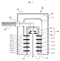
- FIG. 1 is a longitudinal sectional view of an electron beam generator of Example 1 according to one embodiment of the present invention.
- the electron beam generator 21 includes a metal housing 101 filled with an insulating gas 102, an electron gun 103 and a shield 112 disposed inside the metal housing 101, and a shield 112 disposed below the electron gun 103.
- accelerating electrodes 111-1 to n insulating materials 112-1 to n for insulating between them, resistors 113 to n electrically connecting between the accelerating electrodes, multicore cable 109 and bushing 108 Consists of
- the metal housing 101 may partially use a non-metallic member, but the inner surface is desirably made of metal or a conductive material.
- the insulating gas 102 may include sulfur hexafluoride, nitrogen, carbon dioxide, air, or various compounds containing carbon and fluorine.
- An electron source 104 , a suppressor electrode 105 and an extraction electrode 106 are arranged in a vacuum 107 in the electron gun 103 that constitutes the electron beam generator 21 .
- Below the electron gun 103 there are n acceleration electrodes 111-1 to n, insulating materials 112-1 to n for insulating between them, and resistors 113 to n for electrically connecting between the acceleration electrodes. .
- a high voltage is introduced into the metal housing 101 via a multi-core cable 109 and a bushing 108 connected to an external high voltage generator (not shown), and is applied to the electron gun 103 via wires in the insulating gas 102 .
- Electron source 104 , suppressor electrode 105 , extraction electrode 106 and shield 110 are powered.
- the shield 110 is made of a conductive member such as a metal material.
- Shield 110 is electrically connected to acceleration electrode 111-1, and power is supplied through shield 110 to acceleration electrode 111-1.
- the electron beam 114 can be generated by setting the potentials of the respective parts as follows: electron source 104 ⁇ leading electrode 106 ⁇ acceleration electrode 111-1 . . . acceleration electrode 111-n.
- An insulating paint may be applied to the inner surface of the shield 110 and/or the metal housing 101 .
- the insulating coating preferably has a volume resistivity of 10 12 ⁇ cm or more.
- non-linear resistance materials such as zinc oxide, silicon carbide, barium titanate, etc., whose resistivity depends on the electric field, can be added to the paint to improve insulation reliability due to the effect of relaxing the electric field when foreign matter adheres. is also desirable.
- An electron microscope is configured using the electron beam generator 21 having the above configuration. With the above configuration, by using the shield 110 for power supply from the bushing 108 to the acceleration electrode 111-1, dedicated high-potential wiring is not required, and insulation reliability is not lowered due to electric field concentration in the wiring. Furthermore, the effect of the insulating paint improves the insulation reliability, making it possible to realize a highly reliable insulation structure that does not cause dielectric breakdown.
- a charged particle beam device capable of realizing a highly reliable insulating structure.
- a shield having the same electric potential as that of the accelerating electrode is provided in the insulating gas space between the electron gun and the housing, and the shield is used for power supply from the bushing to the accelerating electrode, thereby providing a dedicated high electric potential. Therefore, it is possible to realize a highly reliable insulating structure that does not cause dielectric breakdown because it does not require wiring and does not cause deterioration in insulation reliability due to electric field concentration in wiring.
- FIG. 3 is a longitudinal sectional view of an electron beam generator of Example 2 according to another example of the present invention.
- the electron beam generator 21a according to this embodiment is characterized in that an electron gun shield 115 is provided between the shield 110 and the electron gun 103 in addition to the configuration of the first embodiment.
- the rest of the configuration is the same as that of the above-described first embodiment, and the same reference numerals are given to the same components as those of the first embodiment, and the description overlapping with that of the first embodiment will be omitted below.
- the electron gun shield 115 shown in FIG. 3 is electrically connected to any part of the electron gun 103 and has the same potential.
- FIG. 3 shows a configuration in which the potential is the same as that of the electron source 104, the configuration is not limited to this.
- the electron gun shield 115 may be electrically connected to the suppressor electrode 105, the extractor electrode 106, or other electrodes provided in the electron gun so as to have the same potential.
- Insulating paint may be applied to the inner surfaces of the shield 110, the metal housing 101 and/or the electron gun shield 115, as in the first embodiment described above.
- the insulating paint shown in the first embodiment may be applied.
- An electron microscope is configured using the electron beam generator 21a having the above configuration.
- the electron gun shield 115 having the same potential as any part of the electron gun 103 is provided between the electron gun 103 and the shield 110 having the same potential as that of the acceleration electrode 111-1. Therefore, it is possible to realize a highly reliable insulating structure that does not cause dielectric breakdown between the electron gun, the acceleration electrode, and the shield having the same potential.
- the shield having the same potential as any part of the electron gun is provided between the shield having the same potential as the acceleration electrode and the electron gun, thereby reducing wiring and terminals. It is possible to provide a charged particle beam device that can realize a highly reliable insulation structure that does not cause insulation breakdown between the electron gun, the acceleration electrode, and the shield of the same potential, because the insulation reliability does not deteriorate due to electric field concentration. becomes.
- FIG. 4 is a longitudinal sectional view of an electron beam generator of Example 3 according to another example of the present invention.
- the electron beam generator 21b according to the present embodiment differs from the first embodiment in that a plurality of bushings 108 and multicore cables 109 are provided.
- the rest of the configuration is the same as that of the above-described first embodiment, and the same reference numerals are given to the same components as those of the first embodiment, and the description overlapping with that of the first embodiment will be omitted below.
- the electron beam generator 21b is different from the electron beam generator 21 of the first embodiment described above in that the bushing 108-1 and the multicore cable 109-1, and the bushing 108-2 and the multicore cable 109 It has -2.
- bushing 108-1 and multicore cable 109-1, and bushing 108-2 and multicore cable 109-2 are arranged on opposite sides of the central axis.
- the bushing 108-1 and the multicore cable 109-1, and the bushing 108-2 and the multicore cable 109-2 are arranged to face each other.
- the arrangement of the bushing 108-1 and the multicore cable 109-1, and the arrangement of the bushing 108-2 and the multicore cable 109-2 are not limited to this.
- bushing 108-1 and multi-core cable 109-1, and bushing 108-2 and multi-core cable 109-2 may be arranged on top of metal housing 101.
- the electron beam generator 21 of the first embodiment the configuration including the bushing 108-1 and the multicore cable 109-1, and the bushing 108-2 and the multicore cable 109-2 has been described.
- the electron beam generator 21a of the second embodiment may be configured to include the bushing 108-1 and the multicore cable 109-1, and the bushing 108-2 and the multicore cable 109-2.
- An electron microscope is configured using the electron beam generator 21b having the above configuration.
- it is possible to realize a highly reliable insulation structure as in Embodiments 1 and 2, and it is possible to use a multi-core cable 109 with a small number of cores and a bushing 108, so that high-potential wiring can be separated by a sufficient distance. It becomes possible to hold and dispose, and a highly reliable insulating structure can be realized.
- Embodiments 1 and 2 in addition to the effects of Embodiments 1 and 2, it is possible to use a multi-core cable and bushing with a small number of cores, and it is possible to arrange high-potential wiring with a sufficient distance, Furthermore, it becomes possible to provide a charged particle beam device capable of realizing a highly reliable insulating structure.
- FIG. 5 is a longitudinal sectional view of an electron beam generator of Example 4 according to another example of the present invention.
- the electron beam generator 21c according to the present embodiment is different from that of the first embodiment in that a control wiring 117, a current introduction terminal 116, and an electron gun controller 118 are provided.
- the rest of the configuration is the same as that of the above-described first embodiment, and the same reference numerals are given to the same components as those of the first embodiment, and the description overlapping with that of the first embodiment will be omitted below.
- the electron beam generator 21c further includes a control wiring 117, a current introduction terminal 116, and an electron gun controller 118 in addition to the electron beam generator 21 of the first embodiment. It is preferable that one or more control wirings 117 and one or more current introduction terminals 116 are provided.
- the control wiring 117 may be an electric wire or an optical cable.
- the control wiring 117 is connected to the electron gun control device 118 through an opening provided in the shield 110, and transmits signals for controlling ON/OFF of the voltage and/or current of the electron gun 103.
- the electron beam generator 21 of the first embodiment is further provided with the control wiring 117, the current introduction terminal 116, and the electron gun control device 118, but the configuration is not limited to this.
- the electron beam generator 21a of the second embodiment or the electron beam generator 21b of the third embodiment may further include the control wiring 117, the current introduction terminal 116, and the electron gun controller 118.
- An electron microscope is configured using the electron beam generator 21c having the above configuration. With the above configuration, it is possible to realize a highly reliable insulating structure as in Embodiments 1, 2, and 3, and to realize ON/OFF control of the voltage and/or current of the electron gun 103. is.
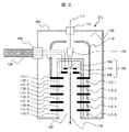
- FIG. 6 is a longitudinal sectional view of an electron beam generator of Example 5 according to another example of the present invention.
- the potential of the shield 110 is not the same as that of the acceleration electrode 111-1, but is the same as that of any one of the electron guns 113. different from 1.
- the rest of the configuration is the same as that of the above-described first embodiment, and the same reference numerals are given to the same components as those of the first embodiment, and the description overlapping with that of the first embodiment will be omitted below.
- the potential of the shield 110 is not the same potential as that of the acceleration electrode 111-1, but is set to any potential of the electron gun 113. Therefore, the shield 110 is It is not electrically connected to the accelerating electrode 111-1, but is electrically connected to one of the electron guns 113 instead. Electric power is supplied to the acceleration electrode 111-1 through the multicore cable 109 and the bushing 108 by the acceleration tube power supply wiring 119 arranged inside the shield 110.
- the wiring 119 for power supply to the accelerating tube is insulated by keeping a sufficient distance from the shield 110 or by arranging an insulating material.
- the wiring 119 for power supply to the accelerating tube may be routed inside the vacuum 107 .
- the potential of the shield 110 shown in FIG. 5 is not the same as that of the acceleration electrode 111-1, but is the potential of one of the electron guns 113. Therefore, the shield 110 is electrically connected to the acceleration electrode 111-1. Instead, the configuration of electrically connecting to any one of the electron guns 113 and the configuration of supplying power to the acceleration electrode 111-1 through the acceleration tube power supply wiring 119 are similar to the electron beam generator 21a of the above-described second embodiment, It can also be applied to the electron beam generator 21b of the third embodiment and the electron beam generator 21c of the fourth embodiment.
- An electron microscope is configured using the electron beam generator 21d having the above configuration. With the above configuration, it is possible to realize a highly reliable insulation structure as in the second, third, or fourth embodiment. According to the present embodiment, it is possible to provide a charged particle beam apparatus capable of realizing a highly reliable insulating structure as in the second to fourth embodiments described above.
- the present invention is not limited to the above-described embodiments, and includes various modifications.
- the above-described embodiments have been described in detail in order to explain the present invention in an easy-to-understand manner, and are not necessarily limited to those having all the described configurations.
- SYMBOLS 1 Charged particle beam apparatus, 2... Housing, 3... Focusing lens control part, 4... Deflection control part, 5... Detection signal processing part, 6... Secondary electron detector, 7... Control device, 8... Display device, 9 external storage medium 10 recipe creating unit 12 image memory 21, 21a, 21b, 21c, 21d electron beam generator 22 focusing lens 23 deflector 24 objective lens 25 sample , 26... Sample holding unit 31... Write address control unit 32... Read address control unit 33... Display control unit 101... Metal housing 102... Insulating gas 103... Electron gun 104... Electron source 105...
- Suppressor electrode 106 Extraction electrode 107 Vacuum 108 Bushing 109 Multicore cable 110 Shield 111 Acceleration electrode 112 Insulator 113 Resistor 114 Electron beam 115 Electron gun Shield 116 Current introduction terminal 117 Control wiring 118 Electron gun control device 119 Accelerating tube power supply wiring
Abstract
Provided is a charged particle beam apparatus capable of realizing a highly reliable insulating structure. This charged particle beam apparatus emits a charged particle beam from a charged particle beam emission device onto a sample, detects charged particles generated from the sample, and creates a sample image or processes the sample. The charged particle beam emission device is provided with a charged particle source and a shield arranged in an interior of a metal housing that is filled with an insulating gas, and an acceleration electrode arranged below the charged particle source, power being supplied to the acceleration electrode via the shield.
Description
本発明は、荷電粒子線装置に係り、特に高信頼な荷電粒子線発生装置を有する荷電粒子線装置に関する。
The present invention relates to a charged particle beam device, and more particularly to a charged particle beam device having a highly reliable charged particle beam generator.
一般的に、電子顕微鏡用の電子ビーム発生装置では電子銃から発生した電子ビームを試料に照射するものと、電子銃から発生した電子ビームを加速管によりさらに加速して試料に照射するものに大別できる。前者は主に大きな電子エネルギーを必要としない走査型電子顕微鏡、後者は主に大きな電子エネルギーを必要とする透過型電子顕微鏡に適用されることが多い。
透過型電子顕微鏡では100kV以上の高電圧を用いるため、絶縁破壊を起こさない高信頼な絶縁構造が必要である。 In general, electron beam generators for electron microscopes are largely divided into those that irradiate the specimen with an electron beam generated from an electron gun, and those that irradiate the specimen with an electron beam generated from the electron gun that is further accelerated by an accelerating tube. can be separated. The former is mainly applied to scanning electron microscopes that do not require large electron energy, and the latter is mainly applied to transmission electron microscopes that require large electron energy.
Since a transmission electron microscope uses a high voltage of 100 kV or higher, a highly reliable insulating structure that does not cause dielectric breakdown is required.
加速管を用いた電子ビーム発生装置の一例として、特許文献1に記載される電子銃がある。特許文献1では、絶縁ガス空間内にシールドを有する高信頼な絶縁構造に、絶縁ガスを循環させて電子銃の冷却を実現している。
構造上、電子銃には突起があり、その突起先端は高電界となるため、放電による絶縁破壊を起こす可能性がある。しかしながら、上述のように高電位のシールドにより電子銃を包囲すると、突起先端の電界を緩和でき、放電による絶縁破壊を抑制できる。
電子銃の各電極或いは加速電極はそれぞれ別の電位とする必要があり、特許文献1では、ケーブルヘッドと呼ぶ多芯のブッシングにより大気中から絶縁ガス中に電流が導入され、絶縁ガス内の配線によりそれぞれに電圧が印加される。 An electron gun described inPatent Document 1 is an example of an electron beam generator using an accelerating tube. In Patent Document 1, cooling of the electron gun is achieved by circulating insulating gas in a highly reliable insulating structure having a shield in an insulating gas space.
Structurally, the electron gun has projections, and since the tip of the projection is in a high electric field, there is a possibility that dielectric breakdown may occur due to discharge. However, by surrounding the electron gun with a high-potential shield as described above, the electric field at the tip of the projection can be relaxed, and dielectric breakdown due to discharge can be suppressed.
Each electrode or acceleration electrode of the electron gun must be set to a different potential. InPatent Document 1, a multi-core bushing called a cable head introduces a current from the air into the insulating gas, A voltage is applied to each by .
構造上、電子銃には突起があり、その突起先端は高電界となるため、放電による絶縁破壊を起こす可能性がある。しかしながら、上述のように高電位のシールドにより電子銃を包囲すると、突起先端の電界を緩和でき、放電による絶縁破壊を抑制できる。
電子銃の各電極或いは加速電極はそれぞれ別の電位とする必要があり、特許文献1では、ケーブルヘッドと呼ぶ多芯のブッシングにより大気中から絶縁ガス中に電流が導入され、絶縁ガス内の配線によりそれぞれに電圧が印加される。 An electron gun described in
Structurally, the electron gun has projections, and since the tip of the projection is in a high electric field, there is a possibility that dielectric breakdown may occur due to discharge. However, by surrounding the electron gun with a high-potential shield as described above, the electric field at the tip of the projection can be relaxed, and dielectric breakdown due to discharge can be suppressed.
Each electrode or acceleration electrode of the electron gun must be set to a different potential. In
しかしながら、特許文献1に開示される構成では、高電位の配線が、配線相互間或いは接地電位である絶縁ガス容器との間で放電し、絶縁破壊を起こす可能性を有することが危惧される。
そこで、本発明は、高信頼な絶縁構造を実現可能な荷電粒子線装置を提供する。 However, in the configuration disclosed inPatent Document 1, it is apprehensive that high-potential wiring may cause electrical discharge between the wiring or between the insulating gas container at ground potential, resulting in dielectric breakdown.
Accordingly, the present invention provides a charged particle beam device capable of realizing a highly reliable insulating structure.
そこで、本発明は、高信頼な絶縁構造を実現可能な荷電粒子線装置を提供する。 However, in the configuration disclosed in
Accordingly, the present invention provides a charged particle beam device capable of realizing a highly reliable insulating structure.
上記課題を解決するため、本発明に係る荷電粒子線装置は、荷電粒子線発生装置から試料に対し荷電粒子線を照射し、試料から発生する荷電粒子を検出し試料画像を生成又は試料を加工する荷電粒子線装置であって、前記荷電粒子線発生装置は、絶縁ガスが満たされた金属製ハウジングの内部に配される荷電粒子源及びシールドと、前記荷電粒子源の下部に配される加速電極と、を備え、前記シールドを介して前記加速電極に給電することを特徴とする。
また、本発明に係る荷電粒子線装置は、荷電粒子線発生装置から試料に対し荷電粒子線を照射し、試料から発生する荷電粒子を検出し試料画像を生成又は試料を加工する荷電粒子線装置であって、前記荷電粒子線発生装置は、絶縁ガスが満たされた金属製ハウジングの内部に配される荷電粒子源及びシールドと、前記荷電粒子源の下部に配される加速電極と、を備え、前記シールドの電位を前記荷電粒子源のいずれかの箇所と同電位とし、前記シールドの内側に配される加速管給電用配線により前記加速電極に給電することを特徴とする。 In order to solve the above problems, a charged particle beam apparatus according to the present invention irradiates a sample with a charged particle beam from a charged particle beam generator, detects the charged particles generated from the sample, and generates a sample image or processes the sample. The charged particle beam generator comprises a charged particle source and a shield arranged inside a metal housing filled with an insulating gas, and an accelerator arranged below the charged particle source. and an electrode, and power is supplied to the acceleration electrode through the shield.
A charged particle beam apparatus according to the present invention irradiates a sample with a charged particle beam from a charged particle beam generator, detects charged particles generated from the sample, and generates a sample image or processes the sample. The charged particle beam generator comprises a charged particle source and a shield arranged inside a metal housing filled with an insulating gas, and an accelerating electrode arranged below the charged particle source. A potential of the shield is set to be the same as that of any part of the charged particle source, and power is supplied to the acceleration electrode by wiring for power supply to the accelerating tube arranged inside the shield.
本発明によれば、高信頼な絶縁構造を実現可能な荷電粒子線装置を提供することが可能となる。
上記した以外の課題、構成及び効果は、以下の実施形態の説明により明らかにされる。 ADVANTAGE OF THE INVENTION According to this invention, it becomes possible to provide the charged particle beam apparatus which can implement|achieve a highly reliable insulation structure.
Problems, configurations, and effects other than those described above will be clarified by the following description of the embodiments.
以下では、本発明の荷電粒子線装置として、試料上に一次電子線を照射し二次元走査することで試料から発生する二次電子を検出し画像形成する走査電子顕微鏡(SEM:Scanning Electron Microscope)を例に説明する。なお、本発明の荷電粒子線装置は、走査電子顕微鏡に限られず、透過型電子顕微鏡(TEM:Transmission Electron Microscope)、走査イオン顕微鏡(SIM:Scanning Ion Microscope)又は収束イオンビーム(FIB:Focused Ion Beam)加工装置等も含まれる。
In the following, the charged particle beam device of the present invention is a scanning electron microscope (SEM) that detects and forms an image of secondary electrons generated from a sample by irradiating a primary electron beam onto the sample and scanning it two-dimensionally. will be described as an example. In addition, the charged particle beam device of the present invention is not limited to a scanning electron microscope, but a transmission electron microscope (TEM: Transmission Electron Microscope), a scanning ion microscope (SIM: Scanning Ion Microscope), or a focused ion beam (FIB: Focused Ion Beam) ) processing equipment, etc. are also included.
図2は、本発明の一実施形態に係る荷電粒子線装置の全体構成図である。本実施例における荷電粒子線装置としての走査電子顕微鏡(SEM)1は、図示しない真空排気系により真空状態に維持された筐体2内に、一次電子を放出する電子ビーム発生装置21、電子ビーム発生装置21より放出された一次電子を試料保持部26上の試料25表面上に集束する集束レンズ22、集束された一次電子線28を試料25上で二次元走査可能に偏向する偏向器23、対物レンズ24、一次電子線28の照射により試料25より発生する二次電子27を検出する二次電子検出器6を備えている。
FIG. 2 is an overall configuration diagram of a charged particle beam device according to one embodiment of the present invention. A scanning electron microscope (SEM) 1 as a charged particle beam device in this embodiment includes an electron beam generator 21 that emits primary electrons, an electron beam A focusing lens 22 that focuses the primary electrons emitted from the generator 21 onto the surface of the sample 25 on the sample holder 26, a deflector 23 that deflects the focused primary electron beam 28 so that the sample 25 can be scanned two-dimensionally, An objective lens 24 and a secondary electron detector 6 for detecting secondary electrons 27 generated from a sample 25 by irradiation with a primary electron beam 28 are provided.
また、集束レンズ22への印加電圧を制御する集束レンズ制御部3、制御装置7から指令値として供給される一次電子線28の偏向量に基づき偏向器23を制御する偏向制御部4、二次電子検出器6からの信号に基づき画像データを生成する検出信号処理部5を備えている。ここで、二次電子検出器6は、試料25から発生する二次電子27が衝突することにより発光する蛍光体、光信号を電気信号に変換し増幅する光電子増倍管から構成される。なお、二次電子検出器6として、半導体検出器等を用いても良い。また、検出信号処理部5は、図示しない光電子増倍管からの電気信号を増幅するアンプ、増幅後の電気信号をディジタル信号に変換するA/D変換器、A/D変換器からのディジタル信号及び偏向制御部4から偏向器23へ出力される偏向量及び走査タイミングに基づいて各画素における輝度を算出し画像データを生成する画像形成部を有している。
Also, a focusing lens control unit 3 for controlling the voltage applied to the focusing lens 22, a deflection control unit 4 for controlling the deflector 23 based on the deflection amount of the primary electron beam 28 supplied as a command value from the control device 7, a secondary A detection signal processing unit 5 for generating image data based on the signal from the electron detector 6 is provided. Here, the secondary electron detector 6 is composed of a phosphor that emits light upon collision with secondary electrons 27 generated from the sample 25, and a photomultiplier tube that converts an optical signal into an electrical signal and amplifies the electrical signal. A semiconductor detector or the like may be used as the secondary electron detector 6 . The detection signal processing unit 5 also includes an amplifier that amplifies an electric signal from a photomultiplier tube (not shown), an A/D converter that converts the amplified electric signal into a digital signal, and a digital signal from the A/D converter. and an image forming section that calculates the brightness of each pixel based on the deflection amount and scanning timing output from the deflection control section 4 to the deflector 23 and generates image data.
更に、走査電子顕微鏡1は、バス11を介して、集束レンズ制御部3、偏向制御部4、検出信号処理部5及び外部記憶媒体9と接続される制御装置7及び表示装置8を備えている。外部記憶媒体9には、検出信号処理部5により生成された画像データあるいはパターン形状情報(CADデータ等)を格納可能となっている。
Further, the scanning electron microscope 1 includes a control device 7 and a display device 8 which are connected via a bus 11 to the focusing lens control section 3, the deflection control section 4, the detection signal processing section 5, and the external storage medium 9. . The external storage medium 9 can store image data or pattern shape information (CAD data, etc.) generated by the detection signal processing unit 5 .
以下では、荷電粒子線装置の一例として、電子顕微鏡を構成する荷電粒子線発生装置としての電子ビーム発生装置の詳細について図面を用いて、実施例を説明する。
なお、電子銃を荷電粒子源の一例として、電子銃シールドを荷電粒子源シールドの一例として説明する。また、電子銃制御装置を荷電粒子源制御装置の一例として説明する。 Hereinafter, as an example of a charged particle beam device, details of an electron beam generator as a charged particle beam generator that constitutes an electron microscope will be described with reference to the drawings.
Note that the electron gun will be described as an example of the charged particle source, and the electron gun shield will be described as an example of the charged particle source shield. Also, the electron gun controller will be described as an example of the charged particle source controller.
図1は、本発明の一実施例に係る実施例1の電子ビーム発生装置の縦断面図である。
図1に示すように、電子ビーム発生装置21は、絶縁ガス102が満たされた金属製ハウジング101、金属製ハウジング101の内部に配される電子銃103とシールド112、電子銃103の下部に配されるn個の加速電極111-1~n,それらの間を絶縁する絶縁材112-1~n,各加速電極間を電気的に接続する抵抗器113~n、多芯ケーブル109及びブッシング108にて構成される。 FIG. 1 is a longitudinal sectional view of an electron beam generator of Example 1 according to one embodiment of the present invention.
As shown in FIG. 1, theelectron beam generator 21 includes a metal housing 101 filled with an insulating gas 102, an electron gun 103 and a shield 112 disposed inside the metal housing 101, and a shield 112 disposed below the electron gun 103. n accelerating electrodes 111-1 to n, insulating materials 112-1 to n for insulating between them, resistors 113 to n electrically connecting between the accelerating electrodes, multicore cable 109 and bushing 108 Consists of
図1に示すように、電子ビーム発生装置21は、絶縁ガス102が満たされた金属製ハウジング101、金属製ハウジング101の内部に配される電子銃103とシールド112、電子銃103の下部に配されるn個の加速電極111-1~n,それらの間を絶縁する絶縁材112-1~n,各加速電極間を電気的に接続する抵抗器113~n、多芯ケーブル109及びブッシング108にて構成される。 FIG. 1 is a longitudinal sectional view of an electron beam generator of Example 1 according to one embodiment of the present invention.
As shown in FIG. 1, the
金属製ハウジング101は、一部に非金属製の部材を使用しても良いが、内面は金属或いは導電性の材質であることが望ましい。
絶縁ガス102は、六フッ化硫黄,窒素,二酸化炭素,空気,或いは炭素とフッ素を含む各種化合物が挙げられる。 Themetal housing 101 may partially use a non-metallic member, but the inner surface is desirably made of metal or a conductive material.
Theinsulating gas 102 may include sulfur hexafluoride, nitrogen, carbon dioxide, air, or various compounds containing carbon and fluorine.
絶縁ガス102は、六フッ化硫黄,窒素,二酸化炭素,空気,或いは炭素とフッ素を含む各種化合物が挙げられる。 The
The
電子ビーム発生装置21を構成する電子銃103には、電子源104、サプレッサ電極105、及び引き出し電極106が真空107中に配置されている。電子銃103の下部には、n個の加速電極111-1~n,それらの間を絶縁する絶縁材112-1~n,各加速電極間を電気的に接続する抵抗器113~nがある。
An electron source 104 , a suppressor electrode 105 and an extraction electrode 106 are arranged in a vacuum 107 in the electron gun 103 that constitutes the electron beam generator 21 . Below the electron gun 103, there are n acceleration electrodes 111-1 to n, insulating materials 112-1 to n for insulating between them, and resistors 113 to n for electrically connecting between the acceleration electrodes. .
外部の高電圧発生装置(図示せず)と接続した多芯ケーブル109及びブッシング108を介して、高電圧が金属製ハウジング101内に導入され、絶縁ガス102内の配線を介して電子銃103の電子源104、サプレッサ電極105、引き出し電極106、及びシールド110に給電される。ここでシールド110は、導電性部材、例えば、金属材料からなる。
シールド110は、加速電極111-1と電気的に接続されており、加速電極111-1はシールド110を介して給電される。
上述の構成において、各部の電位を、電子源104<引き出し電極106<加速電極111-1・・・加速電極111-n、とすることにより電子ビーム114を発生することができる。 A high voltage is introduced into themetal housing 101 via a multi-core cable 109 and a bushing 108 connected to an external high voltage generator (not shown), and is applied to the electron gun 103 via wires in the insulating gas 102 . Electron source 104 , suppressor electrode 105 , extraction electrode 106 and shield 110 are powered. Here, the shield 110 is made of a conductive member such as a metal material.
Shield 110 is electrically connected to acceleration electrode 111-1, and power is supplied through shield 110 to acceleration electrode 111-1.
In the above-described configuration, theelectron beam 114 can be generated by setting the potentials of the respective parts as follows: electron source 104<leading electrode 106<acceleration electrode 111-1 . . . acceleration electrode 111-n.
シールド110は、加速電極111-1と電気的に接続されており、加速電極111-1はシールド110を介して給電される。
上述の構成において、各部の電位を、電子源104<引き出し電極106<加速電極111-1・・・加速電極111-n、とすることにより電子ビーム114を発生することができる。 A high voltage is introduced into the
In the above-described configuration, the
シールド110及び/又は金属製ハウジング101の内面に絶縁性塗料を塗布してもよい。絶縁性塗料は体積抵抗率1012Ωcm以上が望ましい。
また、塗料の中に、異物付着時の電界緩和効果により絶縁信頼性を高めることが可能な酸化亜鉛,炭化ケイ素,チタン酸バリウム等の抵抗率の電界依存性を有する非線形抵抗材料を添加することも望ましい。
上記構成の電子ビーム発生装置21を用いて電子顕微鏡を構成する。
上記構成により、ブッシング108から加速電極111-1への給電にシールド110を用いることにより、専用の高電位の配線を必要とせず、配線の電界集中による絶縁信頼性の低下を生じない。
さらに絶縁性塗料の効果により絶縁信頼性が向上し、絶縁破壊を起こさない高信頼な絶縁構造を実現可能である。 An insulating paint may be applied to the inner surface of theshield 110 and/or the metal housing 101 . The insulating coating preferably has a volume resistivity of 10 12 Ωcm or more.
In addition, non-linear resistance materials such as zinc oxide, silicon carbide, barium titanate, etc., whose resistivity depends on the electric field, can be added to the paint to improve insulation reliability due to the effect of relaxing the electric field when foreign matter adheres. is also desirable.
An electron microscope is configured using theelectron beam generator 21 having the above configuration.
With the above configuration, by using theshield 110 for power supply from the bushing 108 to the acceleration electrode 111-1, dedicated high-potential wiring is not required, and insulation reliability is not lowered due to electric field concentration in the wiring.
Furthermore, the effect of the insulating paint improves the insulation reliability, making it possible to realize a highly reliable insulation structure that does not cause dielectric breakdown.
また、塗料の中に、異物付着時の電界緩和効果により絶縁信頼性を高めることが可能な酸化亜鉛,炭化ケイ素,チタン酸バリウム等の抵抗率の電界依存性を有する非線形抵抗材料を添加することも望ましい。
上記構成の電子ビーム発生装置21を用いて電子顕微鏡を構成する。
上記構成により、ブッシング108から加速電極111-1への給電にシールド110を用いることにより、専用の高電位の配線を必要とせず、配線の電界集中による絶縁信頼性の低下を生じない。
さらに絶縁性塗料の効果により絶縁信頼性が向上し、絶縁破壊を起こさない高信頼な絶縁構造を実現可能である。 An insulating paint may be applied to the inner surface of the
In addition, non-linear resistance materials such as zinc oxide, silicon carbide, barium titanate, etc., whose resistivity depends on the electric field, can be added to the paint to improve insulation reliability due to the effect of relaxing the electric field when foreign matter adheres. is also desirable.
An electron microscope is configured using the
With the above configuration, by using the
Furthermore, the effect of the insulating paint improves the insulation reliability, making it possible to realize a highly reliable insulation structure that does not cause dielectric breakdown.
以上の通り本実施例によれば、高信頼な絶縁構造を実現可能な荷電粒子線装置を提供することが可能となる。
また、本実施例によれば、電子銃とハウジングの間の絶縁ガス空間内に加速電極と同電位のシールドを有し、ブッシングから加速電極への給電にシールドを用いることにより、専用の高電位の配線を必要とせず、配線の電界集中による絶縁信頼性の低下を生じないため,絶縁破壊を起こさない高信頼な絶縁構造を実現可能である。 As described above, according to this embodiment, it is possible to provide a charged particle beam device capable of realizing a highly reliable insulating structure.
Further, according to this embodiment, a shield having the same electric potential as that of the accelerating electrode is provided in the insulating gas space between the electron gun and the housing, and the shield is used for power supply from the bushing to the accelerating electrode, thereby providing a dedicated high electric potential. Therefore, it is possible to realize a highly reliable insulating structure that does not cause dielectric breakdown because it does not require wiring and does not cause deterioration in insulation reliability due to electric field concentration in wiring.
図3は、本発明の他の実施例に係る実施例2の電子ビーム発生装置の縦断面図である。本実施例に係る電子ビーム発生装置21aは、上述の実施例1の構成に加えて、シールド110と電子銃103の間に、電子銃シールド115を備える点に特徴を有する。その他の構成は上述の実施例1と同様であり、実施例1と同様の構成要素に同一符号を付し、以下では実施例1と重複する説明を省略する。
FIG. 3 is a longitudinal sectional view of an electron beam generator of Example 2 according to another example of the present invention. The electron beam generator 21a according to this embodiment is characterized in that an electron gun shield 115 is provided between the shield 110 and the electron gun 103 in addition to the configuration of the first embodiment. The rest of the configuration is the same as that of the above-described first embodiment, and the same reference numerals are given to the same components as those of the first embodiment, and the description overlapping with that of the first embodiment will be omitted below.
図3に示される電子銃シールド115は、電子銃103のいずれかの箇所と電気的に接続し同電位となる。図3では電子源104と同電位とする構成を示すが、これに限られるものではない。例えば、電子銃シールド115が、サプレッサ電極105、引き出し電極106、或いは電子銃に備えたその他の電極と電気的に接続し同電位とする構成でも良い。
The electron gun shield 115 shown in FIG. 3 is electrically connected to any part of the electron gun 103 and has the same potential. Although FIG. 3 shows a configuration in which the potential is the same as that of the electron source 104, the configuration is not limited to this. For example, the electron gun shield 115 may be electrically connected to the suppressor electrode 105, the extractor electrode 106, or other electrodes provided in the electron gun so as to have the same potential.
上述の実施例1と同様に、シールド110、金属製ハウジング101及び/又は電子銃シールド115の内面に絶縁性塗料を塗布しても良い。上述の実施例1で示した絶縁性塗料を塗布しても良い。
Insulating paint may be applied to the inner surfaces of the shield 110, the metal housing 101 and/or the electron gun shield 115, as in the first embodiment described above. The insulating paint shown in the first embodiment may be applied.
上記構成の電子ビーム発生装置21aを用いて電子顕微鏡を構成する。
上記構成により、加速電極111-1と同電位のシールド110と電子銃103の間に、電子銃103のいずれかの箇所と同電位の電子銃シールド115を有することにより、配線や端子の電界集中による絶縁信頼性の低下を生じないため、電子銃と加速電極と同電位のシールドの間に絶縁破壊を起こさない高信頼な絶縁構造を実現可能である。 An electron microscope is configured using theelectron beam generator 21a having the above configuration.
With the above configuration, theelectron gun shield 115 having the same potential as any part of the electron gun 103 is provided between the electron gun 103 and the shield 110 having the same potential as that of the acceleration electrode 111-1. Therefore, it is possible to realize a highly reliable insulating structure that does not cause dielectric breakdown between the electron gun, the acceleration electrode, and the shield having the same potential.
上記構成により、加速電極111-1と同電位のシールド110と電子銃103の間に、電子銃103のいずれかの箇所と同電位の電子銃シールド115を有することにより、配線や端子の電界集中による絶縁信頼性の低下を生じないため、電子銃と加速電極と同電位のシールドの間に絶縁破壊を起こさない高信頼な絶縁構造を実現可能である。 An electron microscope is configured using the
With the above configuration, the
本実施例によれば、実施例1の効果に加え、加速電極と同電位のシールドと電子銃の間に、電子銃のいずれかの箇所と同電位のシールドを有することにより、配線や端子の電界集中による絶縁信頼性の低下を生じないため,電子銃と加速電極と同電位のシールドの間に絶縁破壊を起こさない高信頼な絶縁構造を実現可能な荷電粒子線装置を提供することが可能となる。
According to the present embodiment, in addition to the effects of the first embodiment, the shield having the same potential as any part of the electron gun is provided between the shield having the same potential as the acceleration electrode and the electron gun, thereby reducing wiring and terminals. It is possible to provide a charged particle beam device that can realize a highly reliable insulation structure that does not cause insulation breakdown between the electron gun, the acceleration electrode, and the shield of the same potential, because the insulation reliability does not deteriorate due to electric field concentration. becomes.
図4は、本発明の他の実施例に係る実施例3の電子ビーム発生装置の縦断面図である。本実施例に係る電子ビーム発生装置21bでは、ブッシング108と多芯ケーブル109を複数備える点が実施例1と異なる。その他の構成は上述の実施例1と同様であり、実施例1と同様の構成要素に同一符号を付し、以下では実施例1と重複する説明を省略する。
FIG. 4 is a longitudinal sectional view of an electron beam generator of Example 3 according to another example of the present invention. The electron beam generator 21b according to the present embodiment differs from the first embodiment in that a plurality of bushings 108 and multicore cables 109 are provided. The rest of the configuration is the same as that of the above-described first embodiment, and the same reference numerals are given to the same components as those of the first embodiment, and the description overlapping with that of the first embodiment will be omitted below.
図4に示すように、電子ビーム発生装置21bは、上述の実施例1の電子ビーム発生装置21おいて、ブッシング108-1と多芯ケーブル109-1、及びブッシング108-2と多芯ケーブル109-2を備えている。
図4では、ブッシング108-1と多芯ケーブル109-1、及びブッシング108-2と多芯ケーブル109-2を、中心軸に対して反対側に配置している。換言すれば、ブッシング108-1と多芯ケーブル109-1、及びブッシング108-2と多芯ケーブル109-2を、相互に対向するよう配置している。なお、ブッシング108-1と多芯ケーブル109-1、及びブッシング108-2と多芯ケーブル109-2の配置は、これに限られるものではない。例えば、ブッシング108-1と多芯ケーブル109-1、及びブッシング108-2と多芯ケーブル109-2を、金属製ハウジング101の上部に配置しても良い。 As shown in FIG. 4, theelectron beam generator 21b is different from the electron beam generator 21 of the first embodiment described above in that the bushing 108-1 and the multicore cable 109-1, and the bushing 108-2 and the multicore cable 109 It has -2.
In FIG. 4, bushing 108-1 and multicore cable 109-1, and bushing 108-2 and multicore cable 109-2 are arranged on opposite sides of the central axis. In other words, the bushing 108-1 and the multicore cable 109-1, and the bushing 108-2 and the multicore cable 109-2 are arranged to face each other. The arrangement of the bushing 108-1 and the multicore cable 109-1, and the arrangement of the bushing 108-2 and the multicore cable 109-2 are not limited to this. For example, bushing 108-1 and multi-core cable 109-1, and bushing 108-2 and multi-core cable 109-2 may be arranged on top ofmetal housing 101. FIG.
図4では、ブッシング108-1と多芯ケーブル109-1、及びブッシング108-2と多芯ケーブル109-2を、中心軸に対して反対側に配置している。換言すれば、ブッシング108-1と多芯ケーブル109-1、及びブッシング108-2と多芯ケーブル109-2を、相互に対向するよう配置している。なお、ブッシング108-1と多芯ケーブル109-1、及びブッシング108-2と多芯ケーブル109-2の配置は、これに限られるものではない。例えば、ブッシング108-1と多芯ケーブル109-1、及びブッシング108-2と多芯ケーブル109-2を、金属製ハウジング101の上部に配置しても良い。 As shown in FIG. 4, the
In FIG. 4, bushing 108-1 and multicore cable 109-1, and bushing 108-2 and multicore cable 109-2 are arranged on opposite sides of the central axis. In other words, the bushing 108-1 and the multicore cable 109-1, and the bushing 108-2 and the multicore cable 109-2 are arranged to face each other. The arrangement of the bushing 108-1 and the multicore cable 109-1, and the arrangement of the bushing 108-2 and the multicore cable 109-2 are not limited to this. For example, bushing 108-1 and multi-core cable 109-1, and bushing 108-2 and multi-core cable 109-2 may be arranged on top of
なお、図4では、実施例1の電子ビーム発生装置21おいて、ブッシング108-1と多芯ケーブル109-1、及びブッシング108-2と多芯ケーブル109-2を備える構成を説明したがこれに限らず、実施例2の電子ビーム発生装置21aにおいて、ブッシング108-1と多芯ケーブル109-1、及びブッシング108-2と多芯ケーブル109-2を備える構成としても良い。
In FIG. 4, in the electron beam generator 21 of the first embodiment, the configuration including the bushing 108-1 and the multicore cable 109-1, and the bushing 108-2 and the multicore cable 109-2 has been described. However, the electron beam generator 21a of the second embodiment may be configured to include the bushing 108-1 and the multicore cable 109-1, and the bushing 108-2 and the multicore cable 109-2.
上記構成の電子ビーム発生装置21bを用いて電子顕微鏡を構成する。
上記構成により、実施例1及び実施例2と同様に高信頼な絶縁構造を実現可能であるとともに、芯数の少ない多芯ケーブル109及びブッシング108を使用でき、高電位の配線を十分な距離を持って配置することが可能となり、さらに高信頼な絶縁構造を実現可能である。 An electron microscope is configured using theelectron beam generator 21b having the above configuration.
With the above configuration, it is possible to realize a highly reliable insulation structure as inEmbodiments 1 and 2, and it is possible to use a multi-core cable 109 with a small number of cores and a bushing 108, so that high-potential wiring can be separated by a sufficient distance. It becomes possible to hold and dispose, and a highly reliable insulating structure can be realized.
上記構成により、実施例1及び実施例2と同様に高信頼な絶縁構造を実現可能であるとともに、芯数の少ない多芯ケーブル109及びブッシング108を使用でき、高電位の配線を十分な距離を持って配置することが可能となり、さらに高信頼な絶縁構造を実現可能である。 An electron microscope is configured using the
With the above configuration, it is possible to realize a highly reliable insulation structure as in
本実施例によれば、実施例1及び実施例2の効果に加え、芯数の少ない多芯ケーブル及びブッシングを使用でき、高電位の配線を十分な距離を持って配置することが可能となり、さらに高信頼な絶縁構造を実現可能な荷電粒子線装置を提供することが可能となる。
According to this embodiment, in addition to the effects of Embodiments 1 and 2, it is possible to use a multi-core cable and bushing with a small number of cores, and it is possible to arrange high-potential wiring with a sufficient distance, Furthermore, it becomes possible to provide a charged particle beam device capable of realizing a highly reliable insulating structure.
図5は、本発明の他の実施例に係る実施例4の電子ビーム発生装置の縦断面図である。本実施例に係る電子ビーム発生装置21cでは、制御用配線117、電流導入端子116、及び電子銃制御装置118を備える点が実施例1と異なる。その他の構成は上述の実施例1と同様であり、実施例1と同様の構成要素に同一符号を付し、以下では実施例1と重複する説明を省略する。
FIG. 5 is a longitudinal sectional view of an electron beam generator of Example 4 according to another example of the present invention. The electron beam generator 21c according to the present embodiment is different from that of the first embodiment in that a control wiring 117, a current introduction terminal 116, and an electron gun controller 118 are provided. The rest of the configuration is the same as that of the above-described first embodiment, and the same reference numerals are given to the same components as those of the first embodiment, and the description overlapping with that of the first embodiment will be omitted below.
図5に示すように、電子ビーム発生装置21cは、上述の実施例1の電子ビーム発生装置21おいて、更に制御用配線117、電流導入端子116、及び電子銃制御装置118を備える。なお、制御用配線117及び電流導入端子116は一つ以上備えることが好ましい。制御用配線117は電線でも良く、光ケーブルでも構わない。
As shown in FIG. 5, the electron beam generator 21c further includes a control wiring 117, a current introduction terminal 116, and an electron gun controller 118 in addition to the electron beam generator 21 of the first embodiment. It is preferable that one or more control wirings 117 and one or more current introduction terminals 116 are provided. The control wiring 117 may be an electric wire or an optical cable.
制御用配線117はシールド110に設けられた開口を介して、電子銃制御装置118に接続されており、電子銃103の電圧及び/又は電流のON/OFFなどを制御する信号を伝送する。
The control wiring 117 is connected to the electron gun control device 118 through an opening provided in the shield 110, and transmits signals for controlling ON/OFF of the voltage and/or current of the electron gun 103.
なお、図4では、実施例1の電子ビーム発生装置21おいて、更に制御用配線117、電流導入端子116、及び電子銃制御装置118を備える構成としたがこれに限られるものではない。例えば、実施例2の電子ビーム発生装置21a又は実施例3の電子ビーム発生装置21bにおいて、更に制御用配線117、電流導入端子116、及び電子銃制御装置118を備える構成としても良い。
In FIG. 4, the electron beam generator 21 of the first embodiment is further provided with the control wiring 117, the current introduction terminal 116, and the electron gun control device 118, but the configuration is not limited to this. For example, the electron beam generator 21a of the second embodiment or the electron beam generator 21b of the third embodiment may further include the control wiring 117, the current introduction terminal 116, and the electron gun controller 118. FIG.
上記構成の電子ビーム発生装置21cを用いて電子顕微鏡を構成する。
上記構成により、実施例1、実施例2、及び実施例3と同様に高信頼な絶縁構造を実現可能であると共に、電子銃103の電圧及び/又は電流のON/OFFなどの制御を実現可能である。 An electron microscope is configured using theelectron beam generator 21c having the above configuration.
With the above configuration, it is possible to realize a highly reliable insulating structure as in Embodiments 1, 2, and 3, and to realize ON/OFF control of the voltage and/or current of the electron gun 103. is.
上記構成により、実施例1、実施例2、及び実施例3と同様に高信頼な絶縁構造を実現可能であると共に、電子銃103の電圧及び/又は電流のON/OFFなどの制御を実現可能である。 An electron microscope is configured using the
With the above configuration, it is possible to realize a highly reliable insulating structure as in
図6は、本発明の他の実施例に係る実施例5の電子ビーム発生装置の縦断面図である。本実施例に係る電子ビーム発生装置21dでは、シールド110の電位が加速電極111-1と同電位ではなく、シールド110の電位を電子銃113のいずれかの電位と同電位とした点が実施例1と異なる。その他の構成は上述の実施例1と同様であり、実施例1と同様の構成要素に同一符号を付し、以下では実施例1と重複する説明を省略する。
FIG. 6 is a longitudinal sectional view of an electron beam generator of Example 5 according to another example of the present invention. In the electron beam generator 21d according to this embodiment, the potential of the shield 110 is not the same as that of the acceleration electrode 111-1, but is the same as that of any one of the electron guns 113. different from 1. The rest of the configuration is the same as that of the above-described first embodiment, and the same reference numerals are given to the same components as those of the first embodiment, and the description overlapping with that of the first embodiment will be omitted below.
図6に示すように、本実施例に係る電子ビーム発生装置21dでは、シールド110の電位が加速電極111-1と同電位ではなく、電子銃113のいずれかの電位とするため、シールド110は加速電極111-1と電気的に接続されておらず、代わりに電子銃113のいずれかと電気的に接続されている。
多芯ケーブル109及びブッシング108を介して、シールド110の内側に配置した加速管給電用配線119により、加速電極111-1に給電される。
加速管給電用配線119は、シールド110から十分に距離をとるか、絶縁材を配置するかにより、絶縁される。加速管給電用配線119は真空107内部を介しても良い。 As shown in FIG. 6, in theelectron beam generator 21d according to the present embodiment, the potential of the shield 110 is not the same potential as that of the acceleration electrode 111-1, but is set to any potential of the electron gun 113. Therefore, the shield 110 is It is not electrically connected to the accelerating electrode 111-1, but is electrically connected to one of the electron guns 113 instead.
Electric power is supplied to the acceleration electrode 111-1 through themulticore cable 109 and the bushing 108 by the acceleration tube power supply wiring 119 arranged inside the shield 110. FIG.
Thewiring 119 for power supply to the accelerating tube is insulated by keeping a sufficient distance from the shield 110 or by arranging an insulating material. The wiring 119 for power supply to the accelerating tube may be routed inside the vacuum 107 .
多芯ケーブル109及びブッシング108を介して、シールド110の内側に配置した加速管給電用配線119により、加速電極111-1に給電される。
加速管給電用配線119は、シールド110から十分に距離をとるか、絶縁材を配置するかにより、絶縁される。加速管給電用配線119は真空107内部を介しても良い。 As shown in FIG. 6, in the
Electric power is supplied to the acceleration electrode 111-1 through the
The
なお、図5に示す、シールド110の電位が加速電極111-1と同電位ではなく、電子銃113のいずれかの電位とするため、シールド110は加速電極111-1と電気的に接続されておらず、代わりに電子銃113のいずれかと電気的に接続する構成、及び加速管給電用配線119により、加速電極111-1に給電する構成は、上述の実施例2の電子ビーム発生装置21a、実施例3の電子ビーム発生装置21b、及び実施例4の電子ビーム発生装置21cに適用することも可能である。
Note that the potential of the shield 110 shown in FIG. 5 is not the same as that of the acceleration electrode 111-1, but is the potential of one of the electron guns 113. Therefore, the shield 110 is electrically connected to the acceleration electrode 111-1. Instead, the configuration of electrically connecting to any one of the electron guns 113 and the configuration of supplying power to the acceleration electrode 111-1 through the acceleration tube power supply wiring 119 are similar to the electron beam generator 21a of the above-described second embodiment, It can also be applied to the electron beam generator 21b of the third embodiment and the electron beam generator 21c of the fourth embodiment.
上記構成の電子ビーム発生装置21dを用いて電子顕微鏡を構成する。
上記構成により、実施例2、実施例3又は実施例4と同様に高信頼な絶縁構造を実現可能である。
本実施例によれば、上述の実施例2乃至実施例4と同様に高信頼な絶縁構造を実現可能な荷電粒子線装置を提供することが可能となる。 An electron microscope is configured using theelectron beam generator 21d having the above configuration.
With the above configuration, it is possible to realize a highly reliable insulation structure as in the second, third, or fourth embodiment.
According to the present embodiment, it is possible to provide a charged particle beam apparatus capable of realizing a highly reliable insulating structure as in the second to fourth embodiments described above.
上記構成により、実施例2、実施例3又は実施例4と同様に高信頼な絶縁構造を実現可能である。
本実施例によれば、上述の実施例2乃至実施例4と同様に高信頼な絶縁構造を実現可能な荷電粒子線装置を提供することが可能となる。 An electron microscope is configured using the
With the above configuration, it is possible to realize a highly reliable insulation structure as in the second, third, or fourth embodiment.
According to the present embodiment, it is possible to provide a charged particle beam apparatus capable of realizing a highly reliable insulating structure as in the second to fourth embodiments described above.
なお、本発明は上記した実施例に限定されるものではなく、様々な変形例が含まれる。例えば、上記した実施例は本発明を分かりやすく説明するために詳細に説明したものであり、必ずしも説明した全ての構成を備えるものに限定されるものではない。また、ある実施例の構成の一部を他の実施例の構成に置き換えることが可能であり、また、ある実施例の構成に他の実施例の構成を加えることも可能である。
It should be noted that the present invention is not limited to the above-described embodiments, and includes various modifications. For example, the above-described embodiments have been described in detail in order to explain the present invention in an easy-to-understand manner, and are not necessarily limited to those having all the described configurations. In addition, it is possible to replace part of the configuration of one embodiment with the configuration of another embodiment, and it is also possible to add the configuration of another embodiment to the configuration of one embodiment.
1…荷電粒子線装置、2…筐体、3…集束レンズ制御部、4…偏向制御部、5…検出信号処理部、6…二次電子検出器、7…制御装置、8…表示装置、9…外部記憶媒体、10…レシピ作成部、12…画像メモリ、21,21a,21b,21c,21d…電子ビーム発生装置、22…集束レンズ、23…偏向器、24…対物レンズ、25…試料、26…試料保持部、31…書き込みアドレス制御部、32…読み出しアドレス制御部、33…表示制御部、101…金属製ハウジング、102…絶縁ガス、103…電子銃、104…電子源、105…サプレッサ電極、106…引き出し電極、107…真空、108…ブッシング、109…多芯ケーブル、110…シールド、111…加速電極、112…絶縁体、113…抵抗器、114…電子ビーム 、115…電子銃シールド、116…電流導入端子、117…制御用配線、118…電子銃制御装置、119…加速管給電用配線
DESCRIPTION OF SYMBOLS 1... Charged particle beam apparatus, 2... Housing, 3... Focusing lens control part, 4... Deflection control part, 5... Detection signal processing part, 6... Secondary electron detector, 7... Control device, 8... Display device, 9 external storage medium 10 recipe creating unit 12 image memory 21, 21a, 21b, 21c, 21d electron beam generator 22 focusing lens 23 deflector 24 objective lens 25 sample , 26... Sample holding unit 31... Write address control unit 32... Read address control unit 33... Display control unit 101... Metal housing 102... Insulating gas 103... Electron gun 104... Electron source 105... Suppressor electrode 106 Extraction electrode 107 Vacuum 108 Bushing 109 Multicore cable 110 Shield 111 Acceleration electrode 112 Insulator 113 Resistor 114 Electron beam 115 Electron gun Shield 116 Current introduction terminal 117 Control wiring 118 Electron gun control device 119 Accelerating tube power supply wiring
Claims (12)
- 荷電粒子線発生装置から試料に対し荷電粒子線を照射し、試料から発生する荷電粒子を検出し試料画像を生成又は試料を加工する荷電粒子線装置であって、
前記荷電粒子線発生装置は、
絶縁ガスが満たされた金属製ハウジングの内部に配される荷電粒子源及びシールドと、
前記荷電粒子源の下部に配される加速電極と、を備え、
前記シールドを介して前記加速電極に給電することを特徴とすることを特徴とする荷電粒子線装置。 A charged particle beam device that irradiates a sample with a charged particle beam from a charged particle beam generator, detects charged particles generated from the sample, and generates a sample image or processes the sample,
The charged particle beam generator is
a charged particle source and shield disposed within a metallic housing filled with an insulating gas;
and an accelerating electrode arranged below the charged particle source,
A charged particle beam device, wherein power is supplied to the acceleration electrode through the shield. - 請求項1に記載の荷電粒子線装置において、
前記シールドと前記荷電粒子源の間の絶縁ガス空間内に、前記荷電粒子源のいずれかの箇所と同電位の荷電粒子源シールドを有することを特徴とする荷電粒子線装置。 In the charged particle beam device according to claim 1,
A charged particle beam apparatus comprising a charged particle source shield having the same potential as any part of the charged particle source in an insulating gas space between the shield and the charged particle source. - 請求項1に記載の荷電粒子線装置において、
第1の多芯ケーブル及び第1のブッシングと、
第2の多芯ケーブル及び第2のブッシングと、を備え、
前記第1の多芯ケーブル及び第1のブッシングと、前記第2の多芯ケーブル及び第2のブッシングとは相互に異なる位置に配され、前記第1の多芯ケーブル及び第1のブッシングを介して前記加速電極に給電し、前記第2の多芯ケーブル及び第2のブッシングを介して前記荷電粒子源のいずれかの箇所と電気的に接続されることを特徴とする荷電粒子線装置。 In the charged particle beam device according to claim 1,
a first multicore cable and a first bushing;
a second multicore cable and a second bushing;
The first multicore cable and the first bushing and the second multicore cable and the second bushing are arranged at mutually different positions, and the first multicore cable and the first bushing are arranged to and is electrically connected to any part of the charged particle source via the second multicore cable and the second bushing. - 請求項1に記載の荷電粒子線装置において、
一つ以上の制御用配線及び電流導入端子と、
前記シールドに設けられた開口を介して前記制御用配線と接続される荷電粒子源制御装置と、を備え、
前記荷電粒子源制御装置は、前記荷電粒子源の電圧及び/又は電流のON/OFFの制御を行うことを特徴とする荷電粒子線装置。 In the charged particle beam device according to claim 1,
one or more control wiring and current introduction terminals;
a charged particle source control device connected to the control wiring through an opening provided in the shield,
A charged particle beam apparatus, wherein the charged particle source controller performs ON/OFF control of voltage and/or current of the charged particle source. - 請求項1に記載の荷電粒子線装置において、
前記シールド及び/又は前記金属製ハウジングの内面に絶縁性を有する塗装がされていることを特徴とする荷電粒子線装置。 In the charged particle beam device according to claim 1,
A charged particle beam device, wherein an inner surface of the shield and/or the metal housing is coated with an insulating coating. - 請求項2に記載の荷電粒子線装置において、
少なくとも、前記シールド及び前記金属製ハウジング並びに前記荷電粒子源シールドの内面に絶縁性を有する塗装がされていることを特徴とする荷電粒子線装置。 In the charged particle beam device according to claim 2,
A charged particle beam device, wherein at least inner surfaces of the shield, the metal housing, and the charged particle source shield are coated with an insulating coating. - 請求項3に記載の荷電粒子線装置において、
前記シールド及び/又は前記金属製ハウジングの内面に絶縁性を有する塗装がされていることを特徴とする荷電粒子線装置。 In the charged particle beam device according to claim 3,
A charged particle beam device, wherein an inner surface of the shield and/or the metal housing is coated with an insulating coating. - 請求項4に記載の荷電粒子線装置において、
前記シールド及び/又は前記金属製ハウジングの内面に絶縁性を有する塗装がされていることを特徴とする荷電粒子線装置。 In the charged particle beam device according to claim 4,
A charged particle beam device, wherein an inner surface of the shield and/or the metal housing is coated with an insulating coating. - 請求項2に記載の荷電粒子線装置において、
第1の多芯ケーブル及び第1のブッシングと、
第2の多芯ケーブル及び第2のブッシングと、を備え、
前記第1の多芯ケーブル及び第1のブッシングと、前記第2の多芯ケーブル及び第2のブッシングとは相互に異なる位置に配され、前記第1の多芯ケーブル及び第1のブッシングを介して前記加速電極に給電し、前記第2の多芯ケーブル及び第2のブッシングを介して前記荷電粒子源のいずれかの箇所と電気的に接続されることを特徴とする荷電粒子線装置。 In the charged particle beam device according to claim 2,
a first multicore cable and a first bushing;
a second multicore cable and a second bushing;
The first multicore cable and the first bushing and the second multicore cable and the second bushing are arranged at mutually different positions, and the first multicore cable and the first bushing are arranged to and is electrically connected to any part of the charged particle source via the second multicore cable and the second bushing. - 請求項2に記載の荷電粒子線装置において、
一つ以上の制御用配線及び電流導入端子と、
前記シールドに設けられた開口を介して前記制御用配線と接続される荷電粒子源制御装置と、を備え、
前記荷電粒子源制御装置は、前記荷電粒子源の電圧及び/又は電流のON/OFFの制御を行うことを特徴とする荷電粒子線装置。 In the charged particle beam device according to claim 2,
one or more control wiring and current introduction terminals;
a charged particle source control device connected to the control wiring through an opening provided in the shield,
A charged particle beam apparatus, wherein the charged particle source controller performs ON/OFF control of voltage and/or current of the charged particle source. - 請求項3に記載の荷電粒子線装置において、
一つ以上の制御用配線及び電流導入端子と、
前記シールドに設けられた開口を介して前記制御用配線と接続される荷電粒子源制御装置と、を備え、
前記荷電粒子源制御装置は、前記荷電粒子源の電圧及び/又は電流のON/OFFの制御を行うことを特徴とする荷電粒子線装置。 In the charged particle beam device according to claim 3,
one or more control wiring and current introduction terminals;
a charged particle source control device connected to the control wiring through an opening provided in the shield,
A charged particle beam apparatus, wherein the charged particle source controller performs ON/OFF control of voltage and/or current of the charged particle source. - 荷電粒子線発生装置から試料に対し荷電粒子線を照射し、試料から発生する荷電粒子を検出し試料画像を生成又は試料を加工する荷電粒子線装置であって、
前記荷電粒子線発生装置は、
絶縁ガスが満たされた金属製ハウジングの内部に配される荷電粒子源及びシールドと、
前記荷電粒子源の下部に配される加速電極と、を備え、
前記シールドの電位を前記荷電粒子源のいずれかの箇所と同電位とし、
前記シールドの内側に配される加速管給電用配線により前記加速電極に給電することを特徴とする荷電粒子線装置。 A charged particle beam device that irradiates a sample with a charged particle beam from a charged particle beam generator, detects charged particles generated from the sample, and generates a sample image or processes the sample,
The charged particle beam generator is
a charged particle source and shield disposed within a metallic housing filled with an insulating gas;
and an accelerating electrode arranged below the charged particle source,
setting the potential of the shield to the same potential as any part of the charged particle source;
A charged particle beam device, wherein electric power is supplied to the accelerating electrode by wiring for electric power supply to the accelerating tube arranged inside the shield.
Priority Applications (2)
| Application Number | Priority Date | Filing Date | Title |
|---|---|---|---|
| PCT/JP2021/015638 WO2022219790A1 (en) | 2021-04-15 | 2021-04-15 | Charged particle beam apparatus |
| JP2023514287A JPWO2022219790A1 (en) | 2021-04-15 | 2021-04-15 |
Applications Claiming Priority (1)
| Application Number | Priority Date | Filing Date | Title |
|---|---|---|---|
| PCT/JP2021/015638 WO2022219790A1 (en) | 2021-04-15 | 2021-04-15 | Charged particle beam apparatus |
Publications (1)
| Publication Number | Publication Date |
|---|---|
| WO2022219790A1 true WO2022219790A1 (en) | 2022-10-20 |
Family
ID=83640272
Family Applications (1)
| Application Number | Title | Priority Date | Filing Date |
|---|---|---|---|
| PCT/JP2021/015638 WO2022219790A1 (en) | 2021-04-15 | 2021-04-15 | Charged particle beam apparatus |
Country Status (2)
| Country | Link |
|---|---|
| JP (1) | JPWO2022219790A1 (en) |
| WO (1) | WO2022219790A1 (en) |
Citations (4)
| Publication number | Priority date | Publication date | Assignee | Title |
|---|---|---|---|---|
| JPS5568096A (en) * | 1978-11-16 | 1980-05-22 | Nippon Electron Optics Lab | Electron beam generator |
| JPS5948738U (en) * | 1982-09-18 | 1984-03-31 | 日本電子株式会社 | ion source |
| JPS6199958U (en) * | 1984-12-06 | 1986-06-26 | ||
| JPS61153999A (en) * | 1984-12-26 | 1986-07-12 | 株式会社日立製作所 | Charged particle accelerator |
-
2021
- 2021-04-15 JP JP2023514287A patent/JPWO2022219790A1/ja active Pending
- 2021-04-15 WO PCT/JP2021/015638 patent/WO2022219790A1/en active Application Filing
Patent Citations (4)
| Publication number | Priority date | Publication date | Assignee | Title |
|---|---|---|---|---|
| JPS5568096A (en) * | 1978-11-16 | 1980-05-22 | Nippon Electron Optics Lab | Electron beam generator |
| JPS5948738U (en) * | 1982-09-18 | 1984-03-31 | 日本電子株式会社 | ion source |
| JPS6199958U (en) * | 1984-12-06 | 1986-06-26 | ||
| JPS61153999A (en) * | 1984-12-26 | 1986-07-12 | 株式会社日立製作所 | Charged particle accelerator |
Also Published As
| Publication number | Publication date |
|---|---|
| JPWO2022219790A1 (en) | 2022-10-20 |
Similar Documents
| Publication | Publication Date | Title |
|---|---|---|
| KR100496496B1 (en) | Optical column for charged particle beam device | |
| US4274035A (en) | Field emission electron gun | |
| JP2019021606A (en) | X-ray tube for improving electron focusing | |
| CN105144336A (en) | Electron gun, charged particle gun, and charged particle beam apparatus using electron gun and charged particle gun | |
| US6693282B1 (en) | Particle-optical apparatus including a particle source that can be switched between high brightness and large beam current | |
| WO2022219790A1 (en) | Charged particle beam apparatus | |
| WO2010001953A1 (en) | Electron source device, ion source device and charged particle source device | |
| US6657193B2 (en) | Scanning electron microscope | |
| JPH04233146A (en) | Charged corpuscular beam device | |
| US20090295269A1 (en) | Electron beam generator | |
| JP4246372B2 (en) | Electron beam generation apparatus and electron beam exposure apparatus | |
| JP2002270125A (en) | High voltage electric appliance | |
| JP3485888B2 (en) | Electron beam writing apparatus and semiconductor device manufactured using the same | |
| JP4246373B2 (en) | Electron beam generation apparatus and electron beam exposure apparatus | |
| US11139139B2 (en) | Charged particle beam generator and charged particle beam apparatus | |
| US3303345A (en) | Image amplifier with magnification grid | |
| US3938001A (en) | Protection circuit for electron gun | |
| US6740888B2 (en) | Electron beam apparatus | |
| WO2020213109A1 (en) | Electron source and charged particle beam device | |
| JPS6340017B2 (en) | ||
| US3358173A (en) | Beam generating system for electron tubes with a high breakdown strength | |
| SU692430A1 (en) | Gas-discharge electron gun | |
| KR20160029966A (en) | Electron Beam Gun having Concave Cathode and Holder | |
| KR830000415B1 (en) | Field Emission Gun | |
| JP2930701B2 (en) | Field emission type electron gun |
Legal Events
| Date | Code | Title | Description |
|---|---|---|---|
| 121 | Ep: the epo has been informed by wipo that ep was designated in this application |
Ref document number: 21936986 Country of ref document: EP Kind code of ref document: A1 |
|
| ENP | Entry into the national phase |
Ref document number: 2023514287 Country of ref document: JP Kind code of ref document: A |
|
| NENP | Non-entry into the national phase |
Ref country code: DE |
|
| 122 | Ep: pct application non-entry in european phase |
Ref document number: 21936986 Country of ref document: EP Kind code of ref document: A1 |