WO2022215420A1 - 蒸発燃料処理装置の故障診断装置 - Google Patents
蒸発燃料処理装置の故障診断装置 Download PDFInfo
- Publication number
- WO2022215420A1 WO2022215420A1 PCT/JP2022/010244 JP2022010244W WO2022215420A1 WO 2022215420 A1 WO2022215420 A1 WO 2022215420A1 JP 2022010244 W JP2022010244 W JP 2022010244W WO 2022215420 A1 WO2022215420 A1 WO 2022215420A1
- Authority
- WO
- WIPO (PCT)
- Prior art keywords
- fuel
- canister
- case
- pressure
- failure diagnosis
- Prior art date
- Legal status (The legal status is an assumption and is not a legal conclusion. Google has not performed a legal analysis and makes no representation as to the accuracy of the status listed.)
- Ceased
Links
Images



Classifications
-
- F—MECHANICAL ENGINEERING; LIGHTING; HEATING; WEAPONS; BLASTING
- F02—COMBUSTION ENGINES; HOT-GAS OR COMBUSTION-PRODUCT ENGINE PLANTS
- F02M—SUPPLYING COMBUSTION ENGINES IN GENERAL WITH COMBUSTIBLE MIXTURES OR CONSTITUENTS THEREOF
- F02M25/00—Engine-pertinent apparatus for adding non-fuel substances or small quantities of secondary fuel to combustion-air, main fuel or fuel-air mixture
- F02M25/08—Engine-pertinent apparatus for adding non-fuel substances or small quantities of secondary fuel to combustion-air, main fuel or fuel-air mixture adding fuel vapours drawn from engine fuel reservoir
-
- F—MECHANICAL ENGINEERING; LIGHTING; HEATING; WEAPONS; BLASTING
- F02—COMBUSTION ENGINES; HOT-GAS OR COMBUSTION-PRODUCT ENGINE PLANTS
- F02M—SUPPLYING COMBUSTION ENGINES IN GENERAL WITH COMBUSTIBLE MIXTURES OR CONSTITUENTS THEREOF
- F02M37/00—Apparatus or systems for feeding liquid fuel from storage containers to carburettors or fuel-injection apparatus; Arrangements for purifying liquid fuel specially adapted for, or arranged on, internal-combustion engines
Definitions
- the technology disclosed in this specification relates to a failure diagnosis device for an evaporative fuel processing device.
- the evaporative fuel processing device absorbs and captures the evaporative fuel generated in the fuel tank with a canister. Evaporated fuel captured by the canister is released from the canister and burned in the engine for disposal. Alternatively, evaporative fuel from the canister is circulated to the fuel tank.
- a structure in which the canister is installed in the fuel tank has been considered (hereinafter referred to as a canister structure installed in the fuel tank). This structure has the advantage that even if there is a problem that the vaporized fuel leaks from the canister, the vaporized fuel will not leak into the atmosphere.
- a fault diagnosis device that diagnoses faults related to the airtightness of the evaporative fuel processing device.
- a canister or the like has a detection hole for detecting airtightness.
- the fault diagnosis device for the evaporated fuel processing device disclosed in this specification accommodates the canister in a case inside the fuel tank. Diagnosis of airtightness of the canister is performed only when fuel does not enter the case.
- one of the present disclosure is a failure diagnosis device for an evaporated fuel processing device.
- the fault diagnosis device includes a canister that absorbs and captures fuel vapor generated within the fuel tank.
- a vapor passage is provided that connects the canister and the fuel tank to introduce vaporized fuel generated in the fuel tank.
- a vapor valve for opening and closing the vapor passage is provided in the vapor passage.
- a purge passage is provided in communication with the canister to permit purging of vaporized fuel from the canister.
- a purge valve for opening and closing the purge passage is provided in the purge passage.
- a case containing the canister is provided within the fuel tank. The case shields the canister from fuel within the fuel tank. A gap through which fuel can flow is formed between the case and the outer surface of the canister.
- the fault diagnosis device has fault diagnosis means (fault diagnosis circuit).
- the failure diagnosis means applies either high or low air pressure with respect to atmospheric pressure to the inside of the canister, and performs failure diagnosis regarding the airtightness of the canister based on the pressure inside the canister after the application of the air pressure.
- Fuel detection means (fuel detection circuit) detects the presence or absence of fuel touching the canister within the case. The fuel detection means performs fault diagnosis only when the presence of fuel is not detected.
- the fuel detection means includes a liquid level sensor installed in the gap between the case and the canister.
- the liquid level sensor detects the presence of fuel from the position of a float that floats on the liquid surface of the fuel present in the gap within the case. Therefore, the presence of fuel can be easily detected by a fuel detection means using a general-purpose float.
- the fuel detection means includes a detection element that is cooled by fuel to change electrical resistance.
- the detection element is provided at a position submerged in the lowest level of fuel to be detected in the gap between the case and the canister. Therefore, the presence of fuel can be easily detected with a detection element having no moving parts.
- the fuel detection means includes a detection passage that communicates the canister with the interior of the case.
- the detection passage has a hole communicating with the canister and an opening communicating with the case.
- a hole has a larger open area than an opening.
- the opening is a hole to be detected in fault diagnosis relating to airtightness of the canister and is provided at a position that is buried in the lowest level of fuel to be detected in the case.
- the detection passage is provided with an on-off valve that opens and closes the detection passage.
- the fuel detection means blocks all passages communicating with the canister and opens the on-off valve. In this state, the judging means of the failure diagnosis means applies an air pressure higher or lower than the atmospheric pressure into the canister, and judges the presence or absence of fuel in the case from the pressure change in the canister.
- the on-off valve is opened. In this state, an air pressure higher or lower than the atmospheric pressure is applied inside the canister. Based on the pressure change in the canister at this time, it is determined whether or not the opening of the detection passage is closed by the fuel. Therefore, it is possible to detect whether or not there is fuel in the case from the pressure change in the canister.
- the case is closed with respect to the fuel tank so that the fuel in the fuel tank does not enter the gap between the case and the canister.
- An atmosphere communication passage is provided for communicating the gap in the case with the atmosphere when the judging means judges whether or not there is fuel in the gap in the case.
- the case is sealed so that the fuel in the fuel tank does not flow into the gap between the case and the canister. Therefore, it is possible to prevent fuel and condensed water from entering the case.
- the pressure change in the canister does not increase even when the on-off valve of the detection passage is open. Therefore, since the pressure change in the canister becomes small, it becomes difficult to determine whether or not the opening of the detection passage is closed by the fuel.
- the on-off valve is opened, the gap in the case communicates with the atmosphere through the atmosphere communication passage. Specifically, the opening of the detection passage may not be closed by the fuel.
- the fault diagnosis means includes air pressure generation means (air pressure generation circuit).
- the air pressure generating means applies either high or low air pressure to the atmospheric pressure inside the canister in order to determine whether or not there is fuel in the gap between the case and the canister.
- the air pressure generating means is shared with the air pressure generating means for applying either high or low air pressure to the atmospheric pressure in the canister for failure diagnosis in the failure diagnosis means.
- the air pressure generating means is used for two purposes. That is, the air pressure generating means is used to determine whether or not fuel exists in the gap within the case, and is used for fault diagnosis in the fault diagnosis means. Therefore, the configuration of the entire system can be simplified.
- a first support is installed in the gap between the case and the canister.
- the first strut supports the wall surface of the case that deforms due to the pressure difference between the fuel tank internal pressure and the case internal pressure.
- the pressure inside the fuel tank may be higher than the pressure in the gap inside the case.
- a second strut is installed in the gap between the fuel tank and the canister.
- the second strut supports the wall surface of the case that deforms due to the differential pressure between the fuel tank internal pressure and the case internal pressure.
- the internal pressure of the fuel tank may become lower than the pressure in the gap inside the case.
- the deformation of the case in the direction of narrowing the fuel tank is supported by the second struts, and the deformation of the case can be suppressed.
- the internal pressure of the fuel tank may become lower than the atmospheric pressure. In this case, the deformation of the bottom of the fuel tank toward the bottom of the case can be suppressed by being supported by the second strut.
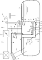
- FIG. 1 is a system configuration diagram of a first embodiment
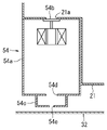
- FIG. FIG. 2 is an enlarged view of a liquid entry detection module portion in FIG. 1
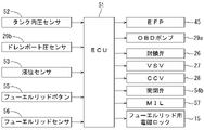
- 3 is a block diagram of a control circuit in the first embodiment
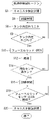
- FIG. 4 is a flow chart showing a control routine during refueling in the control circuit of the first embodiment
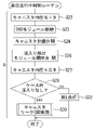
- FIG. 5 is a flowchart similar to FIG. 4 showing a control routine during vehicle travel
- FIG. 5 is a flowchart similar to FIG. 4 showing a parking control routine
- FIG. 1 is an example applied to a vehicle gasoline engine 40 .
- the present technology can also be applied to engines other than vehicles.
- the engine 40 sucks air through an intake pipe 41 .
- Intake air is cleaned through an air cleaner 44 provided at the tip of the intake pipe 41 .
- a throttle valve 43 is provided in the intake pipe 41 downstream of the air cleaner 44 .
- the throttle valve 43 can control the amount of intake air.
- a fuel injection valve 42 that supplies fuel to the cylinders of the engine 40 is provided downstream of the throttle valve 43 in the intake pipe 41 .
- the fuel supplied to the engine 40 is stored in the fuel tank 10 as shown in FIG.
- a fuel pump 45 for pumping fuel to the fuel injection valve 42 is provided at the bottom of the fuel tank 10 .
- the fuel pump 45 is housed inside the sub-tank 13 .
- the sub-tank 13 is a container fixed to the bottom of the fuel tank 10 .
- a fuel pump 45 supplies fuel in the sub-tank 13 to the fuel injection valve 42 through a fuel pipe 46 .
- a pressure regulator 47 is provided in the middle of the fuel pipe 46 for adjusting the fuel pressure supplied to the fuel injection valve 42 to a constant pressure.
- the fuel tank 10 employs an in-fuel-tank canister structure in which a canister 21 is installed inside the fuel tank 10 .
- the fuel tank 10 is connected to a filler pipe 11 for supplying fuel to the inside of the fuel tank 10 .
- Fuel is supplied to the fuel tank 10 by inserting the tip of a fuel gun (not shown) into the upper end opening (not shown) of the filler pipe 11 .
- a fuel cap (not shown) is provided at the upper end opening of the filler pipe 11 .
- the fuel cap prevents the fuel in the fuel tank 10 from flowing back through the filler pipe 11 and leaking out to the outside.
- the outside of the fuel cap is covered with a fuel lid (not shown) for theft prevention.
- the fuel lid is locked in a closed state by a fuel lid electromagnetic lock 15 (see FIG. 3).
- a fuel lid electromagnetic lock 15 see FIG. 3
- the fuel lid is opened by an urging spring (not shown) by electrically unlocking.
- the fuel lid is manually closed against the biasing force of the biasing spring.
- the fuel lid electromagnetic lock 15 is locked and closed.
- An air filter 14 is provided at the upper end opening of the filler pipe 11 as shown in FIG.
- the air filter 14 is also connected to the tip of an air passage 24 that supplies air to the canister 21 . Therefore, the air filter 14 also removes dust and the like from the atmosphere supplied to the canister 21 .
- a sender gauge 71 is provided on the outer wall of the fuel pump 45 as shown in FIG.
- the sender gauge 71 includes a float arm 71b that is swingably supported on the outer wall of the fuel pump 45.
- a float 71a made of a material that floats on the fuel surface is supported at the tip of the float arm 71b.
- the float 71 a moves up and down according to the liquid level of the fuel in the fuel tank 10 .
- the float arm 71b swings according to the vertical movement of the float 71a.
- the sender gauge 71 detects the remaining amount of fuel in the fuel tank 10 based on the swing angle of the float arm 71b.
- an opening is formed in the upper portion of the fuel tank 10 .
- This opening is covered with a set plate 12 .
- a canister 21 and a case 31 are fixed to the lower surface of the set plate 12 .
- a fuel pump 45 and a canister 21 are inserted into the fuel tank 10 through the opening.
- a set plate 12 closes the opening.
- the case 31 covers the side and bottom surfaces of the canister 21 . Therefore, the canister 21 is shielded from the fuel in the fuel tank 10 by the case 31 . Between the outer surface of the canister 21 and the inner surface of the case 31, a gap is formed through which fuel can flow.
- the canister 21 accommodates inside activated carbon that adsorbs evaporated fuel generated in the fuel tank 10 .
- the canister 21 communicates with the vapor phase of the fuel tank 10 via the vapor passage 22 .
- the vapor passage 22 is formed using the space above the gap between the canister 21 and the case 31 .
- a block valve 26 (corresponding to a vapor valve) driven by a step motor is provided in the middle of the vapor passage 22 .
- the block valve 26 is adapted to open and close the vapor passage 22 .
- a labyrinth structure 25 is provided at the fuel tank 10 side opening of the vapor passage 22 .
- the labyrinth structure 25 is configured to allow evaporative fuel to flow into the vapor passage 22 from the fuel tank 10, but to prevent liquid fuel from flowing. Moreover, the vapor passage 22 communicates with the space inside the case 3 . Therefore, even if the liquid fuel passes through the labyrinth structure 25 and flows into the vapor passage 22 , the liquid fuel falls to the lower part of the inner space of the case 3 . Thereby, it is possible to suppress the liquid fuel from adhering to the block valve 26 .
- the canister 21 is communicated with a purge passage 23 and an atmosphere passage 24 through the set plate 12 .
- a distal end of the purge passage 23 communicates with the intake pipe 41 downstream of the throttle valve 43 .
- a purge valve 27 that is, for example, an electromagnetic valve is provided in the middle of the purge passage 23 . Therefore, the purge passage 23 can be opened and closed by the purge valve 27 .
- the tip of the atmosphere passage 24 communicates with the air filter 14 described above.
- a canister shutoff valve 28 which is, for example, an electromagnetic valve and a failure diagnosis module 29 are provided in the air passage 24 . Therefore, the air passage 24 can be opened and closed by the canister block valve 28 .
- case 31 is hermetically sealed with respect to the fuel tank 10 .
- the case 31 communicates with the atmosphere passage 24 through the atmosphere communication passage 32 .
- One end of the atmosphere communication passage 32 communicates with the atmosphere passage 24 between the canister block valve 28 and the failure diagnosis module 29 .
- a liquid level sensor 53 is provided on the upper outer wall of the case 31 as shown in FIG.
- the liquid level sensor 53 has a rod 53a that penetrates through the set plate 12 and is vertically supported.
- a float 53b is slidably supported by the rod 53a through which the rod 53a is passed.
- the rod 53a and float 53b are housed in a container 53c.
- the container 53 c is fixed to a corner sandwiched between the lower surface of the set plate 12 and the outer wall surface of the case 31 .
- a bottom surface of the container 53c communicates with the inside of the fuel tank 10 .
- the float 53b is made of a material that floats on the liquid surface of the fuel.
- the liquid level sensor 53 outputs an electrical signal to the control circuit 51 according to the sliding position of the float 53b with respect to the rod 53a.
- the liquid level sensor 53 is provided at a high position within the fuel tank 10 so that it can detect that the fuel in the fuel tank 10 is full.
- a gap is formed between the outer surface of the canister 21 and the inner surface of the case 31 as shown in FIG.
- a liquid entry detection module 54 (corresponding to a detection passage or fuel detection means) is provided in the gap.
- a side surface of the detection module 54 is attached to the outer wall surface of the canister 21 .
- the liquid detection module 54 has large and small containers arranged vertically. The upper large container forms the passage portion 54a.
- a small container on the lower side constitutes the detection portion 54c.
- the passage portion 54a communicates with the interior of the canister 21 through the communication hole 21a.
- the passage portion 54a communicates with the detection portion 54c through a communication hole 54d. Further, the detection portion 54c communicates with a gap in the case 31 through an opening 54e.
- the communication hole 21a can be opened and closed by an on-off valve 54b, such as an electromagnetic valve, provided in the passage portion 54a.
- the opening 54e is set to have a diameter (for example, 1.5 mm) larger than the minimum diameter of the hole (for example, 0.5 mm) that should be detected in the leakage failure diagnosis of the canister 21 .
- the communication holes 21a and 54d have an opening area larger than that of the opening 54e (for example, a diameter of 3 mm or more).
- a portion of the detection portion 54 c having the opening 54 e is arranged close to the inner wall of the bottom surface of the case 31 . That is, the opening 54e is blocked with a small amount of fuel that has entered the case 31. As shown in FIG. Specifically, the opening 54e is located at the lowest level of fuel that should be detected in the case 31. As shown in FIG.
- Whether or not the opening 54e shown in FIG. 2 is blocked by fuel is detected as follows. First, the on-off valve 54b of the liquid detection module 54 is opened. In this state, a negative pressure lower than the atmospheric pressure is applied inside the canister 21 . At this time, it is confirmed whether or not the air pressure inside the canister 21 decreases according to the applied negative pressure. If fuel exists at the position of the opening 54e and the opening 54e is blocked by the fuel, the air pressure in the canister 21 decreases. Therefore, it is possible to detect the presence of fuel at the position of the opening 54e. If there is no fuel at the position of the opening 54e and the opening 54e is open to the gap inside the case 31, the air pressure inside the canister 21 will not decrease.
- a tank deformation suppressing portion 73 is provided on the bottom surface of the fuel tank 10 .
- a plurality of (two in FIG. 1) struts 72 are provided between the tank deformation suppressing portion 73 and the bottom wall of the canister 21 .
- the post 72 penetrates the bottom surface of the case 31 and is also fixed to the bottom surface of the case 2 .
- About two to four pillars 72 are desirable.
- the tank deformation suppressing portion 73 has a size approximately corresponding to the bottom surface of the canister 21 and is fixed to the bottom surface of the fuel tank 10 so as to reinforce the bottom surface.
- Each strut 72 has a brim-shaped joint 72 c welded to the bottom of the case 31 .
- Each strut 72 includes a first strut 72a above the joint 72c and a second strut 72b below the joint 72c.
- the first strut 72 a prevents the bottom of the case 31 from deforming in a direction that reduces the volume of the gap in the case 31 due to the pressure difference between the internal pressure of the fuel tank 10 and the internal pressure of the case 31 .
- the second strut 72b prevents the bottom of the case 31 from deforming in a direction that reduces the volume of the fuel tank 10 due to the pressure difference between the internal pressure of the fuel tank 10 and the internal pressure of the case 31 .
- the second strut 72b prevents the bottom of the fuel tank 10 from deforming toward the bottom of the case 31 due to the pressure difference between the internal pressure of the fuel tank 10 and the atmospheric pressure.
- the joining of the joining portion 72c to the bottom of the case 31 may be performed by another means such as a snap fit other than welding.
- the failure diagnosis module 29 includes an electric failure diagnosis pump 29a (corresponding to air pressure generation means) and a drain port pressure sensor 29b.
- the fault diagnosis pump 29 a can pump air from the canister 21 toward the air filter 14 through the atmosphere passage 24 .
- the drain port pressure sensor 29b detects the pressure inside the canister 21 through the atmosphere passage 24.
- the set plate 12 is also provided with a tank internal pressure sensor 52 .
- the tank internal pressure sensor 52 detects the gas phase pressure in the fuel tank 10 .
- the evaporated fuel processing device is controlled by a control circuit 51 shown in FIG. Furthermore, the control circuit 51 also performs a fault diagnosis regarding the airtightness of the canister 21 . The failure diagnosis is performed by the control circuit 51 together with valve opening control of the fuel injection valve 42 and the like.
- FIG. 3 shows only the parts related to the control of the evaporated fuel processing device and the fault diagnosis of the canister 21.
- An input circuit of the control circuit 51 receives output signals from the tank internal pressure sensor 52, the drain port pressure sensor 29b, the liquid level sensor 53, the fuel lid button 55, and the fuel lid sensor 56.
- the output circuit of the control circuit 51 includes a fuel pump (EFP) 45, a failure diagnosis pump (OBD pump) 29a, a block valve 26, a purge valve (VSV) 27, a canister block valve (CCV) 28, a liquid detection
- EFP fuel pump
- OBD pump failure diagnosis pump
- VSV purge valve
- CCV canister block valve
- MIL liquid detection
- the fuel lid button 55 is an operation button that is operated to open the fuel lid and emits an on/off signal.
- a fuel lid sensor 56 is a sensor that emits a signal when the fuel lid is opened.
- the warning light 57 is a warning light for issuing an abnormality warning to the vehicle driver.
- FIG. 4 shows a control routine during refueling, which is part of the control program of the control circuit 51 .
- This refueling control routine is executed in response to an operation signal when the fuel lid button 55 is operated to refuel the fuel tank 10 .
- the canister shutoff valve 28 is opened in step S2.
- the closing valve 26 is opened in step S4.
- step S6 the tank internal pressure Pt is detected by the tank internal pressure sensor 52 and stored.
- step S8 it is determined whether or not the tank internal pressure Pt of the fuel tank 10 is equal to or lower than the atmospheric pressure Po. While the tank internal pressure Pt is higher than the atmospheric pressure Po, a negative determination is made in step S8.
- step S8 When the tank internal pressure Pt becomes equal to or lower than the atmospheric pressure Po, an affirmative determination is made in step S8, and the process proceeds to step S10 and subsequent steps. That is, it waits until the tank internal pressure Pt becomes equal to or lower than the atmospheric pressure Po. This prevents the evaporated fuel in the fuel tank 10 from being released into the atmosphere through the filler pipe 11 when the fuel cap is opened after step S10.
- the fuel lid electromagnetic lock 15 is energized to open the fuel lid.
- the fuel cap can be manually opened as in step S12 to refuel with the refueling gun.
- vaporized fuel is likely to be generated in the fuel tank 10, and the generated vaporized fuel is adsorbed and captured by the activated carbon in the canister 21 via the labyrinth structure 25, the vapor passage 22, and the shutoff valve 26. .
- step S14 in FIG. 4 it is determined whether or not the fuel tank 10 is full from the detection signal of the liquid level sensor 53 during refueling.
- the blockage valve 26 is closed in step S16.
- the shutoff valve 26 is closed during refueling, the pressure inside the fuel tank 10 rises sharply.
- fuel injection by the fuel gun is automatically stopped by the automatic stop function of the fuel gun.
- the user pulls out the refueling gun from the filler pipe 11 and closes the fuel cap.
- step S20 the canister shutoff valve 28 is closed, and the processing of the during-refueling control routine ends.
- vaporized fuel is absorbed and captured by the canister 21 through the vapor passage 22 during refueling.
- the pressure in the intake pipe 41 becomes negative, and the purge valve 27 is opened, the evaporated fuel is purged from the canister 21 .
- the vaporized fuel is sucked into the engine 40 through the purge passage 23 and the intake pipe 41 and burned.
- the blocking valve 26 is closed, but the canister blocking valve 28 is opened. Therefore, air is supplied into the canister 21 through the air filter 14 and the canister shutoff valve 28 .
- the vaporized fuel adsorbed and captured by the canister 21 is desorbed and purged.
- FIG. 5 shows a vehicle running control routine which is part of the control program of the control circuit 51 .
- This vehicle running control routine is executed when the vehicle running state is detected.
- the pressure in the canister 21 is detected and stored in step S22.
- the pressure inside the canister 21 is detected by the drain port pressure sensor 29b.
- the failure diagnosis pump 29a of the failure diagnosis module 29 is driven.
- the canister shutoff valve 28 is opened.
- the on-off valve 54b of the liquid detection module 54 is opened.
- the driving time of the failure diagnosis pump 29a and the time during which the canister blocking valve 28 and the on-off valve 54b are opened are predetermined times.
- the failure diagnosis pump 29a is stopped, and the canister shutoff valve 28 and the open/close valve 54b are closed.
- step S27 the pressure inside the canister 21 is again detected and stored.
- step S28 in FIG. 5 it is determined whether fuel has flowed into the case 31 or not. This determination is made based on whether or not the pressure in the canister 21 becomes lower than a predetermined set value by driving the failure diagnosis pump 29a.
- the opening 54 e of the liquid detection module 54 may be closed by fuel that has flowed into the case 31 . In this case, the pressure in the canister 21 decreases with the driving time of the trouble diagnosis pump 29a.
- step S28 the pressure difference stored in steps S22 and S27 is obtained. If the pressure difference is smaller than a predetermined set value, the determination is affirmative that there is no fuel in the case 31 . On the other hand, if the pressure difference is greater than the predetermined set value, it is assumed that there is fuel in the case 31 and a negative determination is made in step S28.
- step S28 in Fig. 5 If step S28 in Fig. 5 is affirmatively determined, fault diagnosis regarding the airtightness of the canister 21 is performed in step S30. If a negative determination is made in step S28, a warning light (MIL) (corresponding to warning means) 57 (see FIG. 3) is turned on in step S32 to issue an abnormality warning. At this time, the driver of the vehicle can recognize that there is fuel in the case 31 and that the airtightness of the canister 21 cannot be diagnosed.
- MIL warning light
- the canister blocking valve 28 is closed after being opened once. Therefore, even if fuel exists in the case 31, the fuel is prevented from being released into the atmosphere through the atmosphere communication passage 32, the canister block valve 28, and the atmosphere passage 24.
- step S30 a fault diagnosis regarding the airtightness of the canister 21 is performed.
- the canister shutoff valve 28 is opened while the shutoff valve 26 and the purge valve 27 are closed.
- the on-off valve 54b of the liquid detection module 54 is closed.
- the inside of the canister 21 becomes a negative pressure lower than the atmospheric pressure.
- the failure diagnosis pump 29a of the failure diagnosis module 29 is operated for a certain period of time.
- the trouble diagnosis pump 29a is stopped and the canister shutoff valve 28 is closed.
- the pressure change in the canister 21 detected by the drain port pressure sensor 29b is monitored.
- step S30 corresponds to failure diagnosis means.
- step S28 corresponds to fuel detection means and determination means.
- the airtightness diagnosis of the canister 21 is performed. On the other hand, no fault diagnosis is performed when fuel is present. Therefore, it is possible to prevent erroneous failure diagnosis in a state where there is fuel in the gap inside the case 31 . Further, when the airtightness of the canister 21 is diagnosed, the airtightness of the case 31 can also be diagnosed at the same time.
- FIG. 6 shows a parking control routine that is part of the control program of the control circuit 51 .
- This parking control routine is executed when it is detected that the vehicle is parked.
- the in-parking control routine is executed, in step S50, the same processing as in the in-vehicle running control routine in FIG. 5 (indicated by "A" in FIG. 5) is performed. That is, the failure diagnosis regarding the airtightness of the canister 21 is performed in a state where no fuel exists in the case 31 . Further, in step S60, a fault diagnosis regarding airtightness of the fuel tank 10 is performed.
- the fault diagnosis relating to the airtightness of the fuel tank 10 is well known and will not be described in detail.
- Figures 7 and 8 show a second embodiment.
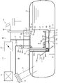
- the second embodiment has a thermistor 59 (corresponding to a detection element and fuel detection means) instead of the liquid level sensor 53 and the liquid detection module 54 in the first embodiment.
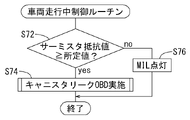
- the vehicle running control routine of FIG. 8 is executed instead of FIG. 5 in the first embodiment.
- the rest of the configuration of the second embodiment is the same as that of the first embodiment, and repetitive description of the same parts will be omitted.
- a thermistor 59 is fixed to the inner wall surface of the bottom of the case 31 as shown in FIG.
- a detection signal of the thermistor 59 is output as an electrical signal to the control circuit 51 similar to that of the first embodiment.
- the thermistor 59 is a positive characteristic thermistor (PTC thermistor).
- PTC thermistor positive characteristic thermistor
- step S72 it is determined in step S72 whether or not the resistance value of the thermistor 59 is equal to or greater than a predetermined value. Thereby, it is determined whether or not fuel has flowed into the case 31 .
- the resistance value of the thermistor 59 becomes greater than the predetermined value.
- An affirmative determination is made in step S72, and a failure diagnosis regarding the airtightness of the canister 21 is performed in step S74.
- step S76 the warning light (MIL) 57 is turned on to issue an abnormality warning. At this time, the driver of the vehicle can recognize that there is fuel in the case 31 and that the airtightness of the canister 21 cannot be diagnosed.
- MIL warning light
- ⁇ Third Embodiment> 9 and 10 show a third embodiment.
- the resistance value of the thermistor 59 is used to detect whether fuel is present in the case 31 .
- whether or not fuel exists in the case 31 is detected by the detection signal of the liquid level sensor 58 .
- the vehicle running control routine of FIG. 10 is executed instead of FIG. 8 in the second embodiment. The rest of the configuration of the third embodiment is the same as that of the second embodiment, and repeated description of the same parts will be omitted.
- the liquid level sensor 58 is provided within the case 31 in a gap between the outer wall of the canister 21 and the canister 21 .
- the liquid level sensor 58 has a rod 58a that extends through the set plate 12 and is vertically supported.
- a float 58b slidably supported by the rod 58a is supported by the rod 58a.
- the float 58b is made of a material that floats on the liquid surface of the fuel.
- the liquid level sensor 58 outputs an electrical signal corresponding to the sliding position of the float 58b with respect to the rod 58a to the control circuit 51 similar to that of the first embodiment.
- the liquid level sensor 58 detects fuel that has flowed into the gap inside the case 31 .
- the liquid level sensor 58 is provided so that the entire area in the height direction within the case 31 is a detection area.
- step S92 it is determined in step S92 whether or not the detection signal of the liquid level sensor 58 is equal to or less than a predetermined value Le.
- the predetermined value Le corresponds to the liquid level when the lowest level of fuel to be detected exists in the case 31 .
- the detection signal of the liquid level sensor 58 is less than or equal to the predetermined value Le.
- an affirmative determination is made in step S92, and a failure diagnosis regarding the airtightness of the canister 21 is performed in step S94.
- the detection signal of the liquid level sensor 58 becomes larger than the predetermined value Le.
- a negative determination is made in step S92. Therefore, in step S96, the warning light (MIL) 57 is turned on to issue an abnormality warning. At this time, the driver of the vehicle can recognize that there is fuel in the case 31 and that the airtightness of the canister 21 cannot be diagnosed.
- MIL warning light
- the third embodiment it is detected whether or not there is fuel in the gap between the case 31 and the canister 21 .
- a fault diagnosis regarding the airtightness of the canister 21 is performed only when there is no fuel. No diagnostics are performed when fuel is present. Therefore, it is possible to prevent erroneous failure diagnosis in a state where there is fuel in the gap inside the case 31 .
- an electric pump is used to create a negative pressure in the canister that is lower than the atmospheric pressure.
- a system may be adopted in which an electric pump is used to make the inside of the canister a positive pressure higher than the atmospheric pressure.
- a method may be adopted in which an air pump (for example, a jet pump) other than an electric pump is used to create a negative pressure lower than the atmospheric pressure or a positive pressure higher than the atmospheric pressure in the canister.
- a system in which the negative pressure generated by the engine is applied to the inside of the canister may be adopted. Each of these methods is known in Japanese Patent No. 5318793 or the like.
- the inside of the canister is made to have a negative pressure lower than the atmospheric pressure when diagnosing the airtightness of the canister.
- a fault diagnosis was then made based on the rate at which the negative pressure changes toward atmospheric pressure.
- a positive pressure higher than atmospheric pressure or a negative pressure lower than atmospheric pressure is applied in the canister.
- Failure diagnosis may be performed based on the rate of change in pressure before and after the start of application.
- the canister airtightness diagnosis may be performed using an evaporative chock module (known in Japanese Patent No. 3896588, etc.).
- failure diagnosis is performed by applying a positive pressure higher than the atmospheric pressure or a negative pressure lower than the atmospheric pressure into the canister.
- a passage is provided with a reference hole whose size corresponds to the hole in the canister to be detected.
- a reference pressure for diagnosis is set in advance by applying the same air pressure to this passage as during failure diagnosis.
- the failure diagnosis pump 29 a of the failure diagnosis module 29 introduces negative pressure into the canister 21 .
- the liquid detection module 54 determines whether fuel has entered the case 31 or not.
- a negative pressure may be introduced into the canister 21 using a dedicated pump instead of the failure diagnosis pump 29a.
- a positive pressure may be introduced into the canister 21 instead of the negative pressure.
- the determination as to whether or not fuel has entered the case 31 is made based on the pressure change before and after the introduction of the negative pressure into the canister 21 is started. Instead of this, the determination may be made based on the pressure change after the introduction of the negative pressure into the canister 21 is completed.
- a positive characteristic thermistor (PTC thermistor) is used as the detection element.
- a negative characteristic thermistor (NTC thermistor) may be used as the sensing element.
- the sub-tank is provided at the bottom of the fuel tank. Alternatively, the sub-tank can be omitted.
- the control circuit 51 has at least one programmed electronic processor.
- the control circuit 51 includes memory that stores instructions or software that are executed by the electronic processor to implement at least one function of the control circuit 51 described herein.
- control circuitry 51 may be implemented as a microprocessor with a separate memory.
- the control circuit 51 can include volatile or non-volatile memory.
- suitable control circuit 51 memories include RAM (random access memory), flash memory, ROM (read only memory), PROM (programmable read only memory), EPROM (erasable programmable read only memory). ), EEPROM (Electrically Erasable Programmable Read Only Memory)), registers, magnetic disks, optical disks, hard drives, other suitable storage media, or combinations thereof.
- processor central processing unit
- CPU central processing unit
- Software includes, for example, firmware, one or more applications, program data, filters, rules, one or more program modules, and other executable instructions.
Landscapes
- Engineering & Computer Science (AREA)
- Chemical & Material Sciences (AREA)
- Combustion & Propulsion (AREA)
- Mechanical Engineering (AREA)
- General Engineering & Computer Science (AREA)
- Supplying Secondary Fuel Or The Like To Fuel, Air Or Fuel-Air Mixtures (AREA)
Abstract
ケース(31)は、キャニスタ(21)を収容して燃料タンク(10)内に設けられる。ケース(31)は、燃料タンク(10)内の燃料からキャニスタ(21)を遮蔽する。ケース(31)は、キャニスタ(21)の外表面との間に燃料が流入可能な隙間を形成する。故障診断手段は、キャニスタ(21)内に大気圧より高い正圧、若しくは大気圧より低い負圧を印加する。そして故障診断手段は、その印加開始前後、若しくは印加終了後のキャニスタ(21)内の圧力変化によりキャニスタ(21)の気密性に関する故障診断を行う。
Description
本明細書に開示の技術は、蒸発燃料処理装置の故障診断装置に関する。
蒸発燃料処理装置では、燃料タンク内で発生する蒸発燃料をキャニスタで吸着して捕捉する。キャニスタで捕捉した蒸発燃料をキャニスタから放出させて、エンジンで燃焼させて処理する。あるいはキャニスタからの蒸発燃料を燃料タンクに環流させる。キャニスタを燃料タンク内に設置する構造が考えられている(以下、燃料タンク内設置キャニスタ構造という)。この構造では、キャニスタから蒸発燃料が漏れるトラブルが生じても、その蒸発燃料が大気中に漏れないという利点がある。
一方、蒸発燃料処理装置の気密性に関する故障診断を行う故障診断装置がある。燃料タンク内設置キャニスタを用いた蒸発燃料処理装置では、キャニスタの気密性に関する故障診断を正確に行うことができない場合があった。例えば、キャニスタ等に気密性を検出するための検出孔が開いている。しかし故障診断を行う際にキャニスタ周りに燃料が付着して、燃料が検出孔を外側から塞いでしまう場合がある。この場合、故障診断を正確に行うことができない。そこで、キャニスタをケース内に収容して燃料タンク内に設置することでキャニスタ周辺に燃料が付着しないようにしている(特開2005-54704号公報参照)。
しかし、意に反してケース内に燃料タンク内の燃料が浸入するおそれがある。この場合、検出用孔が内側から燃料により塞がれる。そのため、気密性に関する故障診断を正確に行うことができない場合がある。
本明細書が開示する蒸発燃料処理装置の故障診断装置は、燃料タンク内でキャニスタをケース内に収容する。キャニスタの気密性に関する故障診断を、ケース内へ燃料が浸入していないときのみ行う。
例えば、本開示の1つは、蒸発燃料処理装置の故障診断装置である。故障診断装置は、燃料タンク内で発生する蒸発燃料を吸着して捕捉するキャニスタを備える。キャニスタと燃料タンクを接続して燃料タンク内で発生した蒸発燃料を導入するベーパ通路が設けられる。ベーパ通路を開閉するベーパ弁がベーパ通路に設けられる。キャニスタと連結されてキャニスタから蒸発燃料がパージするのを許容するパージ通路が設けられる。パージ通路を開閉するパージ弁がパージ通路に設けられる。キャニスタを収容するケースが燃料タンク内に設けられる。ケースは、燃料タンク内の燃料からキャニスタを遮蔽する。ケースとキャニスタの外表面との間に燃料が流入可能な隙間が形成される。故障診断装置は、故障診断手段(故障診断回路)を有する。故障診断手段は、大気圧に対して高低いずれかの空気圧をキャニスタ内に印加し、空気圧印加後のキャニスタ内の圧力によりキャニスタの気密性に関する故障診断を行う。燃料検出手段(燃料検出回路)は、ケース内でキャニスタに触れる燃料の存否を検出する。燃料検出手段は、燃料の存在が検出されない状態でのみ故障診断を実行する。
したがって、ケース内でキャニスタとの隙間に燃料があるか否かを検出する。燃料がないときのみキャニスタの気密性に関する故障診断を行う。燃料が存在するときは故障診断を行わない。そのため、ケース内の隙間に燃料がある状態で誤った故障診断を行うことを防止することができる。
本開示の他の1つの例において、燃料検出手段は、ケースとキャニスタとの隙間に設置される液位センサを含む。液位センサは、ケース内の隙間に存在する燃料の液面に浮くフロートの位置により燃料の存在を検出する。したがって汎用のフロートを用いた燃料検出手段により簡単に燃料の存在を検出することができる。
本開示の他の1つの例において、燃料検出手段は、燃料に冷却されて電気抵抗を変化させる検出素子を含む。検出素子は、ケースとキャニスタとの隙間で検出されるべき最低レベルの燃料に埋没する位置に設けられている。したがって、可動部なしの検出素子で簡単に燃料の存在を検出することができる。
本開示の他の1つの例において、燃料検出手段は、キャニスタをケース内に連通させる検出通路を備える。検出通路は、キャニスタに連通する孔と、ケースに連通する開口を有する。孔は、開口よりも開口面積が大きい。開口は、キャニスタの気密性に関する故障診断において検出されるべき孔で且つケース内で検出されるべき最低レベルの燃料に埋没する位置に設けられている。検出通路には、検出通路を開閉する開閉弁が設けられる。燃料検出手段は、キャニスタに連通する通路を全て遮断し、且つ開閉弁を開く。その状態で、故障診断手段の判定手段が、キャニスタ内に大気圧に対して高低いずれかの空気圧を印加し、キャニスタ内の圧力変化によりケース内の燃料の存否を判定する。
したがって、キャニスタに連通する通路を全て遮断する一方、開閉弁を開く。その状態で、キャニスタ内に大気圧に対して高低いずれかの空気圧が印加する。この時のキャニスタ内の圧力変化により、検出通路の開口が燃料により閉じられているか否かが判定される。従って、キャニスタ内の圧力変化によってケース内に燃料があるか否かを検出することができる。
本開示の他の1つの例において、ケースは、ケースとキャニスタの隙間に燃料タンク内の燃料が浸入しないように燃料タンクに対して閉鎖されている。判定手段によりケース内の隙間における燃料の存否を判定するとき、ケース内の隙間を大気に連通する大気連通路が設けられている。
したがって、ケースとキャニスタとの隙間に燃料タンクの燃料が流入しないようにケースが密閉されている。そのため、ケース内に燃料や凝縮水が入らないようにすることができる。しかし、ケースが密閉されていると、検出通路の開閉弁を開いた状態で、キャニスタ内の圧力変化は大きくならない。したがって、キャニスタ内の圧力変化が小さくなるため、検出通路の開口が燃料により閉じられているか否かの判断が容易でなくなる。しかし本構成によれば、開閉弁が開かれたとき、ケース内の隙間は大気連通路を介して大気に連通される。具体的には、検出通路の開口が燃料により閉じられていない場合がある。この場合は、ケースが密閉されていても、開閉弁を開いたとき、キャニスタ内に大気連通路から大気圧が流入する。これによりキャニスタ内の圧力変化が大きくなる。一方、検出通路の開口が燃料により閉じられている場合がある。この場合は、キャニスタ内に大気連通路から大気圧が流入しない。これにより圧力変化は小さくなる。従って、ケース内に燃料が流入しているか否かを精度良く検出することができる。
本開示の他の1つの例において、故障診断手段は、空気圧発生手段(空気圧発生回路)を含む。空気圧発生手段は、ケースとキャニスタの隙間における燃料の存否を判定するためキャニスタ内に大気圧に対して高低いずれかの空気圧を印加する。空気圧発生手段は、故障診断手段における故障診断のためキャニスタ内に大気圧に対して高低いずれかの空気圧を印加する空気圧発生手段と共用されている。
したがって、空気圧発生手段は、2つの用途に利用される。すなわち空気圧発生手段は、ケース内の隙間における燃料の存否を判定するために用いられ、かつ故障診断手段における故障診断のために用いられる。そのため、システム全体の構成を簡素化することができる。
本開示の他の1つの例において、ケースとキャニスタとの隙間に第1の支柱が設置される。第1の支柱は、燃料タンク内圧とケース内圧との差圧により変形するケースの壁面を支持する。例えば、ケース内の隙間の圧力に対して燃料タンク内の圧力が高くなる場合がある。この場合、ケース内の隙間を狭くする方向のケースの変形を第1の支柱が支持し、ケースの変形を抑制することができる。
本開示の他の1つの例において、燃料タンクとキャニスタとの隙間に第2の支柱が設置される。第2の支柱は、燃料タンク内圧とケース内圧との差圧により変形するケースの壁面を支持する。例えば、ケース内の隙間の圧力に対して燃料タンクの内圧が低くなる場合がある。この場合、燃料タンクを狭くする方向のケースの変形を第2の支柱が支持し、ケースの変形を抑制することができる。また、燃料タンクの内圧が大気圧より低くなる場合がある。この場合、燃料タンクの底部がケースの底部に向けて変形するのを、第2の支柱が支持して抑制することができる。
<第1実施形態の全体構成>
図1に示す実施形態は、車両用ガソリンエンジン40に適用した例である。勿論、本件技術は、車両以外のエンジンにも適用可能である。
図1に示す実施形態は、車両用ガソリンエンジン40に適用した例である。勿論、本件技術は、車両以外のエンジンにも適用可能である。
図1に示すようにエンジン40は、吸気管41を通じて空気を吸入している。吸入される空気は、吸気管41の先端に設けられたエアクリーナ44を通じて清浄される。吸気管41には、エアクリーナ44の下流にスロットル弁43が設けられている。スロットル弁43は、吸入空気量を制御可能である。吸気管41において、スロットル弁43の下流には、エンジン40のシリンダ内に燃料を供給する燃料噴射弁42が設けられている。
図1に示すようにエンジン40に供給する燃料は、燃料タンク10に貯留されている。燃料タンク10の底部には、燃料噴射弁42に燃料を圧送するための燃料ポンプ45が設けられている。燃料ポンプ45は、サブタンク13内に収容されている。これにより燃料タンク10内の残留燃料が少ない状態で車両が傾斜しても燃料ポンプ45の燃料吸込口(図示略)に燃料を確保できる。サブタンク13は、燃料タンク10の底部に固定される容器である。燃料ポンプ45は、サブタンク13内の燃料を燃料パイプ46を介して燃料噴射弁42に供給している。燃料パイプ46の途中には、燃料噴射弁42に供給される燃料圧力を一定圧力に調整するプレッシャレギュレータ47が設けられている。燃料タンク10は、燃料タンク10内にキャニスタ21を設置した燃料タンク内設置キャニスタ構造を採用している。
図1に示すように燃料タンク10には、燃料タンク10内に燃料給油を行うためのフィラーパイプ11が接続されている。フィラーパイプ11の上端開口(図示略)に給油ガン(図示略)の先端を挿入して燃料タンク10へ給油が行われる。フィラーパイプ11の上端開口には、フューエルキャップ(図示略)が設けられている。フューエルキャップは、フィラーパイプ11を逆流して燃料タンク10内の燃料が外部に漏れ出ないようにしている。更に、フューエルキャップの外側は、盗難防止等のためフューエルリッド(図示略)により覆われている。フューエルリッドは、フューエルリッド用電磁ロック15(図3参照)により閉じた状態でロックされている。フューエルリッドを開く際は、電気的にロックを解除することにより付勢ばね(図示略)によりフューエルリッドが開放される。また、フューエルリッドは、付勢ばねの付勢力に抗して手動にて閉じる。これによりフューエルリッド用電磁ロック15がロックされて閉じた状態とされる。
図1に示すようにフィラーパイプ11の上端開口部には、エアフィルタ14が設けられている。このエアフィルタ14は、キャニスタ21に大気を供給する大気通路24の先端にも接続されている。したがってエアフィルタ14は、キャニスタ21に供給される大気中の塵等も除去している。
図1に示すように燃料ポンプ45の外壁には、センダゲージ71が設けられている。センダゲージ71は、燃料ポンプ45の外壁に揺動自在に支持されたフロートアーム71bを備える。フロートアーム71bの先端には、燃料の液面に浮く素材により形成されたフロート71aが支持されている。燃料タンク10内の燃料の液位に応じてフロート71aが上下動する。フロート71aの上下動に応じてフロートアーム71bが揺動する。センダゲージ71は、フロートアーム71bの揺動角度によって燃料タンク10内の燃料残量を検出している。
<蒸発燃料処理装置の構成>
図1を参照するように燃料タンク10の上部に開口が形成されている。この開口には、セットプレート12が被せられる。セットプレート12の下面に、キャニスタ21及びケース31が固定される。開口から、燃料タンク10内に燃料ポンプ45及びキャニスタ21が挿入される。セットプレート12により開口が閉鎖される。ケース31は、キャニスタ21の側面及び下面を覆う。従って、キャニスタ21は、ケース31によって燃料タンク10内の燃料から遮蔽されている。そして、キャニスタ21の外表面とケース31内表面との間には、燃料が流入し得る隙間が形成されている。
図1を参照するように燃料タンク10の上部に開口が形成されている。この開口には、セットプレート12が被せられる。セットプレート12の下面に、キャニスタ21及びケース31が固定される。開口から、燃料タンク10内に燃料ポンプ45及びキャニスタ21が挿入される。セットプレート12により開口が閉鎖される。ケース31は、キャニスタ21の側面及び下面を覆う。従って、キャニスタ21は、ケース31によって燃料タンク10内の燃料から遮蔽されている。そして、キャニスタ21の外表面とケース31内表面との間には、燃料が流入し得る隙間が形成されている。
図1に示すようにキャニスタ21は、燃料タンク10内に発生する蒸発燃料を吸着する活性炭を内部に収容している。キャニスタ21は、ベーパ通路22を介して燃料タンク10の気相と連通されている。ベーパ通路22は、キャニスタ21とケース31との隙間の上部空間を利用して形成されている。ベーパ通路22の途中には、ステップモータ駆動の封鎖弁26(ベーパ弁に相当)が設けられている。封鎖弁26は、ベーパ通路22を開閉するようにされている。また、ベーパ通路22の燃料タンク10側開口部には、迷路構造25が設けられている。迷路構造25は、燃料タンク10からベーパ通路22内へ蒸発燃料が流入するのは許容するが、液体燃料が流入するのは抑制するように構成されている。しかも、ベーパ通路22は、ケース3内空間に連通されている。そのため、液体燃料が迷路構造25を通過してベーパ通路22に流入したとしても、液体燃料はケース3内空間下部に落下する。これにより、液体燃料が封鎖弁26に付着するのを抑制することができる。
図1に示すようにキャニスタ21には、セットプレート12を貫通してパージ通路23及び大気通路24が連通されている。パージ通路23の先端は、スロットル弁43より下流側で吸気管41に連通されている。パージ通路23の途中には、例えば電磁弁であるパージ弁27が設けられている。従って、パージ弁27によりパージ通路23は開閉可能とされている。一方、大気通路24の先端は、上述のエアフィルタ14に連通されている。大気通路24の途中には、例えば電磁弁であるキャニスタ封鎖弁28及び故障診断モジュール29が設けられている。従って、キャニスタ封鎖弁28により大気通路24は開閉可能とされている。
<ケース31の構成>
図1に示すようにケース31は、燃料タンク10に対して密封されている。しかし、ケース31は、大気連通路32により、大気通路24に連通されている。大気連通路32の一端は、キャニスタ封鎖弁28と故障診断モジュール29との間において大気通路24に連通されている。
図1に示すようにケース31は、燃料タンク10に対して密封されている。しかし、ケース31は、大気連通路32により、大気通路24に連通されている。大気連通路32の一端は、キャニスタ封鎖弁28と故障診断モジュール29との間において大気通路24に連通されている。
図1に示すようにケース31の上部外壁には、液位センサ53が設けられている。液位センサ53は、セットプレート12を貫通して垂直に支持されたロッド53aを有している。ロッド53aには、ロッド53aが貫通されて摺動自在にフロート53bが支持されている。ロッド53a及びフロート53bは、容器53c内に収容されている。容器53cは、セットプレート12の下面とケース31の外壁面とに挟まれた角部に固定されている。容器53cの底面は、燃料タンク10内に連通されている。フロート53bは、燃料の液面に浮く素材で出来ている。液位センサ53は、フロート53bのロッド53aに対する摺動位置に応じた電気信号を制御回路51に出力する。液位センサ53は、燃料タンク10内の燃料が満タン状態にあることを検出可能とするように、燃料タンク10内の高い位置に設けられている。
図1に示すようにキャニスタ21の外表面とケース31の内表面との間には、隙間が形成される。隙間に液入り検出モジュール54(検出通路、燃料検出手段に相当)が設けられている。検出モジュール54の側面がキャニスタ21の外壁面に装着されている。図2に示すように、液入り検出モジュール54は、上下に連なっている大小の容器を有している。上側の大きい容器が通路部54aを成している。下側の小さい容器が検出部54cを成している。通路部54aは、連通孔21aによりキャニスタ21内に連通されている。通路部54aは、連通孔54dにより検出部54cに連通されている。また、検出部54cは、開口54eによりケース31内の隙間に連通されている。
図2に示すように連通孔21aは、通路部54a内に設けられた例えば電磁弁である開閉弁54bにより開閉可能とされている。また、開口54eは、キャニスタ21のリーク故障診断にて検出されるべき最小の孔の径(例えば、直径0.5mm)よりも大きい径(例えば、直径1.5mm)に設定されている。連通孔21a、54dは、開口54eの開口面積よりも大きい開口面積とされている(例えば、直径3mm以上)。そして、検出部54cにおいて、開口54eを備えた部位はケース31の底面内壁に接近して配置されている。即ち、開口54eは、ケース31内に入った少ない燃料で塞がれる。詳しくは、開口54eは、ケース31内で検出されるべき最低レベルの燃料により埋没する位置とされている。
図2に示す開口54eが燃料により閉塞されているか否かは、下記のように検出する。先ず、液入り検出モジュール54の開閉弁54bを開く。その状態で、キャニスタ21内に大気圧より低い負圧が印加される。このとき、キャニスタ21内の空気圧が、印加された負圧に応じて低下するか否かを確認する。開口54eの位置に燃料が存在して、開口54eが燃料により閉塞されていると、キャニスタ21内の空気圧が低下する。そのため、開口54eの位置に燃料が存在することを検出することができる。開口54eの位置に燃料が存在せず、開口54eがケース31内の隙間に開放されていると、キャニスタ21内の空気圧が低下しない。なぜなら、大気連通路32(図1参照)から供給される大気圧が開口54eを通じてキャニスタ21内に供給されるためである。そのため、開口54eの位置に燃料が存在しないことを検出することができる。即ち、ケース31内でキャニスタ21に触れる燃料が存在しないことを検出することができる。
図1に示すように、燃料タンク10の底面上には、タンク変形抑制部73が設けられる。タンク変形抑制部73とキャニスタ21の底面外壁との間には、複数本(図1では2本)の支柱72が設けられている。支柱72は、ケース31の底面を貫通し、かつケース2の底面にも固定される。支柱72は、2~4本程度が望ましい。タンク変形抑制部73は、概ねキャニスタ21の底面に対応する大きさで燃料タンク10の底面を補強するように底面に固定されている。各支柱72は、ケース31の底部に溶接される鍔状の接合部72cを有している。各支柱72は、接合部72cより上側の第1の支柱72aと、接合部72cより下側の第2の支柱72bを含む。第1の支柱72aは、燃料タンク10の内圧とケース31の内圧との差圧によりケース31の底部がケース31内の隙間の容積を小さくする方向に変形するのを抑制している。また、第2の支柱72bは、燃料タンク10の内圧とケース31の内圧との差圧によりケース31の底部が燃料タンク10の容積を小さくする方向に変形するのを抑制する。更に第2の支柱72bは、燃料タンク10の内圧と大気圧との差圧により燃料タンク10の底部がケース31の底部に向けて変形するのを抑制している。ケース31の底部に対する接合部72cの接合は、溶接による以外、スナップフィット等の別の手段により行われてもよい。
<蒸発燃料処理装置の故障診断装置の構成>
図1に示すように故障診断モジュール29は、電動ポンプである故障診断用ポンプ29a(空気圧発生手段に相当)及びドレンポート圧センサ29bを備える。故障診断用ポンプ29aは、大気通路24を通じてキャニスタ21からエアフィルタ14に向けて空気を圧送可能としている。ドレンポート圧センサ29bは、大気通路24を通じてキャニスタ21内の圧力を検出している。また、セットプレート12には、タンク内圧センサ52が設けられている。タンク内圧センサ52は、燃料タンク10内の気相の圧力を検出している。
図1に示すように故障診断モジュール29は、電動ポンプである故障診断用ポンプ29a(空気圧発生手段に相当)及びドレンポート圧センサ29bを備える。故障診断用ポンプ29aは、大気通路24を通じてキャニスタ21からエアフィルタ14に向けて空気を圧送可能としている。ドレンポート圧センサ29bは、大気通路24を通じてキャニスタ21内の圧力を検出している。また、セットプレート12には、タンク内圧センサ52が設けられている。タンク内圧センサ52は、燃料タンク10内の気相の圧力を検出している。
<制御回路の構成>
蒸発燃料処理装置は、図3に示す制御回路51によって制御される。さらに制御回路51は、キャニスタ21の気密性に関する故障診断も行う。故障診断は、燃料噴射弁42の開弁制御等と共に制御回路51により行われている。図3には、蒸発燃料処理装置の制御及びキャニスタ21の故障診断に関する部分のみを示している。制御回路51の入力回路には、タンク内圧センサ52、ドレンポート圧センサ29b、液位センサ53、フューエルリッドボタン55、及びフューエルリッドセンサ56の各出力信号が入力されている。一方、制御回路51の出力回路には、燃料ポンプ(EFP)45、故障診断用ポンプ(OBDポンプ)29a、封鎖弁26、パージ弁(VSV)27、キャニスタ封鎖弁(CCV)28、液入り検出モジュール54の開閉弁54b、警告灯(MIL)57、及びフューエルリッド用電磁ロック15に各出力信号を出力している。フューエルリッドボタン55は、フューエルリッドを開くために操作されてオンオフ信号を発する操作ボタンである。また、フューエルリッドセンサ56は、フューエルリッドが開かれたとき信号を発するセンサである。更に、警告灯57は、車両運転者に異常警告を発する警告灯である。
蒸発燃料処理装置は、図3に示す制御回路51によって制御される。さらに制御回路51は、キャニスタ21の気密性に関する故障診断も行う。故障診断は、燃料噴射弁42の開弁制御等と共に制御回路51により行われている。図3には、蒸発燃料処理装置の制御及びキャニスタ21の故障診断に関する部分のみを示している。制御回路51の入力回路には、タンク内圧センサ52、ドレンポート圧センサ29b、液位センサ53、フューエルリッドボタン55、及びフューエルリッドセンサ56の各出力信号が入力されている。一方、制御回路51の出力回路には、燃料ポンプ(EFP)45、故障診断用ポンプ(OBDポンプ)29a、封鎖弁26、パージ弁(VSV)27、キャニスタ封鎖弁(CCV)28、液入り検出モジュール54の開閉弁54b、警告灯(MIL)57、及びフューエルリッド用電磁ロック15に各出力信号を出力している。フューエルリッドボタン55は、フューエルリッドを開くために操作されてオンオフ信号を発する操作ボタンである。また、フューエルリッドセンサ56は、フューエルリッドが開かれたとき信号を発するセンサである。更に、警告灯57は、車両運転者に異常警告を発する警告灯である。
<蒸発燃料処理装置の作用>
図4は、制御回路51の制御プログラムの一部である給油中制御ルーチンを示す。この給油中制御ルーチンは、燃料タンク10へ給油を行うべくフューエルリッドボタン55が操作されたとき、その操作信号を受けて実行される。給油中制御ルーチンが実行されると、ステップS2にてキャニスタ封鎖弁28が開かれる。ステップS4において封鎖弁26が開かれる。次にステップS6では、タンク内圧センサ52によってタンク内圧Ptが検出され保存される。ステップS8では、燃料タンク10のタンク内圧Ptが大気圧Po以下となっているか否かが判定される。タンク内圧Ptが大気圧Poより高い間は、ステップS8は否定判断される。タンク内圧Ptが大気圧Po以下となると、ステップS8が肯定判断され、ステップS10以降の処理に進む。すなわちタンク内圧Ptが大気圧Po以下となるのを待つことになる。これにより、ステップS10以降でフューエルキャップを開いたとき燃料タンク10内の蒸発燃料がフィラーパイプ11から大気中に放出されるのを防止している。
図4は、制御回路51の制御プログラムの一部である給油中制御ルーチンを示す。この給油中制御ルーチンは、燃料タンク10へ給油を行うべくフューエルリッドボタン55が操作されたとき、その操作信号を受けて実行される。給油中制御ルーチンが実行されると、ステップS2にてキャニスタ封鎖弁28が開かれる。ステップS4において封鎖弁26が開かれる。次にステップS6では、タンク内圧センサ52によってタンク内圧Ptが検出され保存される。ステップS8では、燃料タンク10のタンク内圧Ptが大気圧Po以下となっているか否かが判定される。タンク内圧Ptが大気圧Poより高い間は、ステップS8は否定判断される。タンク内圧Ptが大気圧Po以下となると、ステップS8が肯定判断され、ステップS10以降の処理に進む。すなわちタンク内圧Ptが大気圧Po以下となるのを待つことになる。これにより、ステップS10以降でフューエルキャップを開いたとき燃料タンク10内の蒸発燃料がフィラーパイプ11から大気中に放出されるのを防止している。
図4のステップS10では、フューエルリッド用電磁ロック15に通電してフューエルリッドを開く。フューエルリッドが開けば、ステップS12のように手動によりフューエルキャップを開いて、給油ガンにより給油を行うことができる。給油中には、燃料タンク10内で蒸発燃料が発生し易く、発生した蒸発燃料は、迷路構造25、ベーパ通路22、及び封鎖弁26を介してキャニスタ21内の活性炭に吸着され、捕捉される。
図4のステップS14では、給油中、液位センサ53の検出信号により燃料タンク10が満タンとなったか否かが判定されている。燃料タンク10が満タンとなり、ステップS14が肯定判断されると、ステップS16において、封鎖弁26が閉じられる。給油中に封鎖弁26が閉じられると、燃料タンク10内の圧力が急激に高まる。これにより、給油ガンによる燃料注入が給油ガンの自動停止機能により自動的に停止される。給油の自動停止に伴って、使用者は、給油ガンをフィラーパイプ11から抜き、フューエルキャップを閉じる。そして、手動にてフューエルリッドを閉じると、ステップS18は肯定判断される。そのため、ステップS20でキャニスタ封鎖弁28が閉じられて給油中制御ルーチンの処理を終了する。
図1を参照するように、給油中に蒸発燃料がベーパ通路22を介してキャニスタ21に吸着され捕捉される。エンジン40が作動され、吸気管41が負圧となり、パージ弁27が開かれたとき、キャニスタ21から蒸発燃料がパージされる。蒸発燃料は、パージ通路23と吸気管41を経てエンジン40に吸入され燃焼される。このとき、封鎖弁26は閉じられているが、キャニスタ封鎖弁28は開かれる。そのため、キャニスタ21内には、エアフィルタ14とキャニスタ封鎖弁28を介して大気が供給される。キャニスタ21に吸着され捕捉された蒸発燃料は脱離されパージされる。
<蒸発燃料処理装置の故障診断装置の作用>
図5は、制御回路51の制御プログラムの一部である車両走行中制御ルーチンを示す。この車両走行中制御ルーチンは、車両走行状態が検出されたとき実行される。車両走行中制御ルーチンが実行されると、ステップS22にてキャニスタ21内の圧力が検出され保存される。キャニスタ21内の圧力検出は、ドレンポート圧センサ29bにより行われる。次にステップS23にて故障診断モジュール29の故障診断用ポンプ29aが駆動される。ステップS24では、キャニスタ封鎖弁28が開かれる。ステップS26では、液入り検出モジュール54の開閉弁54bが開かれる。このときの故障診断用ポンプ29aの駆動時間、並びにキャニスタ封鎖弁28及び開閉弁54bが開かれる時間は、予め決められた時間とされている。この時間が経過すると、故障診断用ポンプ29aは駆動停止され、キャニスタ封鎖弁28及び開閉弁54bは閉じられる。そして、ステップS27にて、再度、キャニスタ21内の圧力が検出され保存される。
図5は、制御回路51の制御プログラムの一部である車両走行中制御ルーチンを示す。この車両走行中制御ルーチンは、車両走行状態が検出されたとき実行される。車両走行中制御ルーチンが実行されると、ステップS22にてキャニスタ21内の圧力が検出され保存される。キャニスタ21内の圧力検出は、ドレンポート圧センサ29bにより行われる。次にステップS23にて故障診断モジュール29の故障診断用ポンプ29aが駆動される。ステップS24では、キャニスタ封鎖弁28が開かれる。ステップS26では、液入り検出モジュール54の開閉弁54bが開かれる。このときの故障診断用ポンプ29aの駆動時間、並びにキャニスタ封鎖弁28及び開閉弁54bが開かれる時間は、予め決められた時間とされている。この時間が経過すると、故障診断用ポンプ29aは駆動停止され、キャニスタ封鎖弁28及び開閉弁54bは閉じられる。そして、ステップS27にて、再度、キャニスタ21内の圧力が検出され保存される。
図5のステップS28では、ケース31内に燃料が流入していないか否かが判定される。この判定は、故障診断用ポンプ29aの駆動によってキャニスタ21内の圧力が予め決められた設定値より低くなるか否かによって行われる。液入り検出モジュール54の開口54eがケース31内に流入した燃料によって閉じられる場合がある。この場合、キャニスタ21内の圧力は故障診断用ポンプ29aの駆動時間とともに低くなる。一方、ケース31内に燃料の流入がなく、液入り検出モジュール54の開口54eに燃料が付着していない場合がある。この場合は、大気連通路32から供給される大気圧がキャニスタ21内に流入してキャニスタ21内の圧力は殆ど低くならない。従って、ステップS28では、ステップS22及びステップS27で保存された圧力差を求める。その圧力差が予め決められた設定値より小さい場合は、ケース31内に燃料がないとして肯定判断される。一方、上記圧力差が予め決められた設定値より大きい場合は、ケース31内に燃料があるとして、ステップS28は否定判断される。
図5のステップS28が肯定判断された場合は、ステップS30にてキャニスタ21の気密性に関する故障診断が実施される。ステップS28が否定判断されると、ステップS32にて警告灯(MIL)(警告手段に相当)57(図3参照)が点灯されて異常警告が行われる。このとき、車両運転者は、ケース31内に燃料が存在し、キャニスタ21の気密性に関する故障診断が実施できないことを認識することができる。
上述のように、キャニスタ封鎖弁28は一旦開かれた後閉じられる。そのため、ケース31内に燃料が存在する場合でも、その燃料が、大気連通路32、キャニスタ封鎖弁28、及び大気通路24を通じて大気中に放出されることは防止される。
ステップS30では、キャニスタ21の気密性に関する故障診断が行われる。この診断では、封鎖弁26及びパージ弁27が閉じられている状態で、キャニスタ封鎖弁28を開く。勿論、液入り検出モジュール54の開閉弁54bは閉じられている。この結果、キャニスタ21内は大気圧よりも低い負圧となる。そして故障診断モジュール29の故障診断用ポンプ29aを一定時間作動させる。故障診断用ポンプ29aを作動停止させてキャニスタ封鎖弁28を閉じる。そして、ドレンポート圧センサ29bによって検出されるキャニスタ21内の圧力変化を監視する。予め決められた時間経過後のキャニスタ21内の圧力の変化速度が所定範囲内か否かを判断する。この判断により、キャニスタ21の周辺に孔あきがないか否かが診断される。キャニスタ21の周辺は、キャニスタ21、並びにパージ弁27よりキャニスタ21側のパージ通路23、及びキャニスタ封鎖弁28よりキャニスタ21側の大気通路24である。同時にケース31に孔あきがないか否かも診断される。なぜなら、キャニスタ21とケース31内は、大気連通路32を介して互いに連通されているためである。ステップS30の処理は、故障診断手段に相当する。また、ステップS28の処理は、燃料検出手段及び判定手段に相当する。
以上のように、ケース31内でキャニスタ21との隙間に燃料があるか否かを検出する。そして、燃料がないときのみキャニスタ21の気密性に関する故障診断を行う。一方、燃料が存在するときは故障診断を行わない。そのため、ケース31内の隙間に燃料がある状態で誤った故障診断を行うことを防止することができる。また、キャニスタ21の気密性に関する故障診断を行う際に、ケース31の気密性に関する故障診断も同時に行うことができる。
図6は、制御回路51の制御プログラムの一部である駐車中制御ルーチンを示す。この駐車中制御ルーチンは、車両が駐車されたことが検出されたときに実行される。駐車中制御ルーチンが実行されると、ステップS50にて、図5の車両走行中制御ルーチンと同様の処理(図5に「A」で示す)が行われる。即ち、ケース31内に燃料が存在しない状態で、キャニスタ21の気密性に関する故障診断が実行される。また、ステップS60にて、燃料タンク10の気密性に関する故障診断が実行される。燃料タンク10の気密性に関する故障診断は、公知であり、詳細な説明は省略する。
<第2実施形態>
図7、8は、第2実施形態を示す。第2実施形態は、第1実施形態における液位センサ53及び液入り検出モジュール54に代えて、サーミスタ59(検出素子及び燃料検出手段に相当)を有している。また第2実施形態は、第1実施形態における図5に代えて図8の車両走行中制御ルーチンを実行する。第2実施形態のその他の構成は、第1実施形態と同一であり、同一部分についての再度の説明は省略する。
図7、8は、第2実施形態を示す。第2実施形態は、第1実施形態における液位センサ53及び液入り検出モジュール54に代えて、サーミスタ59(検出素子及び燃料検出手段に相当)を有している。また第2実施形態は、第1実施形態における図5に代えて図8の車両走行中制御ルーチンを実行する。第2実施形態のその他の構成は、第1実施形態と同一であり、同一部分についての再度の説明は省略する。
図7に示すようにケース31の底部の内壁面には、サーミスタ59が固定されている。サーミスタ59の検出信号は、第1実施形態と同様の制御回路51に電気信号として出力される。サーミスタ59は、正特性のサーミスタ(PTCサーミスタ)である。サーミスタ59は、ケース31内に検出されるべき最低レベルの燃料が存在すると、その燃料に埋没して冷却されて抵抗値が小さくなる。一方、ケース31内に燃料が存在しないと、サーミスタ59は、燃料による冷却が行われないため抵抗値が大きくなる。
図8の車両走行中制御ルーチンが実行されると、ステップS72にてサーミスタ59の抵抗値が所定値以上か否かを判断する。これによりケース31内に燃料が流入していないか否かが判定される。ケース31内に燃料が存在しない場合は、サーミスタ59の抵抗値が所定値より大きくなる。そして、ステップS72は肯定判断され、ステップS74にてキャニスタ21の気密性に関する故障診断が実施される。一方、ケース31内に燃料が存在する場合は、サーミスタ59の抵抗値が所定値より小さくなる。そして、ステップS72は否定判断される。そのため、ステップS76にて警告灯(MIL)57が点灯されて異常警告が行われる。このとき、車両運転者は、ケース31内に燃料が存在し、キャニスタ21の気密性に関する故障診断が実施できないことを認識することができる。
以上のように、第2実施形態においても、ケース31内でキャニスタ21との隙間に燃料があるか否かを検出する。そして燃料がないときのみキャニスタ21の気密性に関する故障診断を行う。燃料が存在するときは故障診断を行わない。そのため、ケース31内の隙間に燃料がある状態で誤った故障診断を行うことを防止することができる。
<第3実施形態>
図9、10は、第3実施形態を示す。第2実施形態では、ケース31内に燃料が存在するか否かをサーミスタ59の抵抗値により検出している。これに対して、第3実施形態では、ケース31内に燃料が存在するか否かを液位センサ58の検出信号により検出する。また第3実施形態は、第2実施形態における図8に代えて図10の車両走行中制御ルーチンを実行する。第3実施形態のその他の構成は、第2実施形態と同一であり、同一部分についての再度の説明は省略する。
図9、10は、第3実施形態を示す。第2実施形態では、ケース31内に燃料が存在するか否かをサーミスタ59の抵抗値により検出している。これに対して、第3実施形態では、ケース31内に燃料が存在するか否かを液位センサ58の検出信号により検出する。また第3実施形態は、第2実施形態における図8に代えて図10の車両走行中制御ルーチンを実行する。第3実施形態のその他の構成は、第2実施形態と同一であり、同一部分についての再度の説明は省略する。
図9のように、液位センサ58は、ケース31内でキャニスタ21の外壁との隙間に設けられている。液位センサ58は、セットプレート12を貫通して垂直に支持されたロッド58aを有している。ロッド58aには、ロッド58aが貫通されて摺動自在に支持されたフロート58bが支持されている。フロート58bは、燃料の液面に浮く素材で出来ている。液位センサ58は、フロート58bのロッド58aに対する摺動位置に応じた電気信号を第1実施形態と同様の制御回路51に出力する。液位センサ58は、ケース31内の隙間に流入した燃料を検出する。しかも液位センサ58は、ケース31内の高さ方向の全域を検出領域とするように設けられている。
図10の車両走行中制御ルーチンが実行されると、ステップS92にて液位センサ58の検出信号が所定値Le以下か否か判定される。所定値Leは、ケース31内に検出されるべき最低レベルの燃料が存在するときの液位に相当する。ケース31内に燃料が存在しない場合は、液位センサ58の検出信号が所定値Le以下となる。このとき、ステップS92は肯定判断され、ステップS94にてキャニスタ21の気密性に関する故障診断が実施される。ケース31内に燃料が存在する場合は、液位センサ58の検出信号が所定値Leより大きくなる。このとき、ステップS92は否定判断される。そのため、ステップS96にて警告灯(MIL)57が点灯されて異常警告が行われる。このとき、車両運転者は、ケース31内に燃料が存在し、キャニスタ21の気密性に関する故障診断が実施できないことを認識することができる。
以上のように、第3実施形態においても、ケース31内でキャニスタ21との隙間に燃料があるか否かを検出する。燃料がないときのみキャニスタ21の気密性に関する故障診断を行。燃料が存在するときは故障診断を行わない。そのため、ケース31内の隙間に燃料がある状態で誤った故障診断を行うことを防止することができる。
<その他の実施形態>
以上、本明細書に開示の技術を特定の実施形態に用いた例について説明したが、その他各種の形態に用いることもできる。例えば、上記実施形態では、キャニスタに捕捉された蒸発燃料の処理を、エンジンに吸入させて燃焼させる方式とした。これに代えて、キャニスタに捕捉された蒸発燃料の処理を、適宜のポンプにより燃料タンク内に環流させる方式(特許第5318793号等にて公知)を採用してもよい。
以上、本明細書に開示の技術を特定の実施形態に用いた例について説明したが、その他各種の形態に用いることもできる。例えば、上記実施形態では、キャニスタに捕捉された蒸発燃料の処理を、エンジンに吸入させて燃焼させる方式とした。これに代えて、キャニスタに捕捉された蒸発燃料の処理を、適宜のポンプにより燃料タンク内に環流させる方式(特許第5318793号等にて公知)を採用してもよい。
上記実施形態では、キャニスタの気密性に関する故障診断を行う際、電動ポンプによりキャニスタ内を大気圧よりも低い負圧とする方式とした。これに代えて、電動ポンプによりキャニスタ内を大気圧よりも高い正圧とする方式を採用してもよい。また、電動ポンプ以外のエアポンプ(例えば、ジェットポンプ等)によりキャニスタ内を大気圧よりも低い負圧、若しくは大気圧よりも高い正圧とする方式を採用してもよい。更に、エンジンが発生する負圧をキャニスタ内に印加する方式を採用してもよい。これらの各方式は、いずれも特許第5318793号等にて公知である。
上記実施形態では、キャニスタの気密性に関する故障診断を行う際、キャニスタ内を大気圧よりも低い負圧とする。その後、負圧が大気圧に向けて変化する速度に基づいて故障診断を行うものとした。これに代えて、キャニスタ内に大気圧よりも高い正圧、若しくは大気圧よりも低い負圧を印加する。その印加開始前後の圧力の変化速度に基づいて故障診断を行うものとしてもよい。これに代えて、キャニスタの気密性に関する故障診断は、エバポリークチョックモジュール(特許第3896588号等にて公知)を用いて行ってもよい。エバポリークチョックモジュールを用いた故障診断では、キャニスタ内に大気圧よりも高い正圧、若しくは大気圧よりも低い負圧を印加して故障診断を行う。この場合、検出されるべきキャニスタの孔に相当する大きさの基準孔を持った通路が設けられる。この通路に故障診断時と同様の空気圧を印加して、診断のための基準圧力を予め設定する。
上記実施形態では、故障診断モジュール29の故障診断用ポンプ29aによりキャニスタ21内に負圧を導入する。この状態で、液入り検出モジュール54によりケース31内に燃料が浸入しているか否かを判定する。故障診断用ポンプ29aに代えて、専用のポンプを用いて、キャニスタ21内に負圧を導入してもよい。また、キャニスタ21内には負圧に代えて正圧を導入するようにしてもよい。上記実施形態では、ケース31内に燃料が浸入しているか否かの判定をキャニスタ21内への負圧導入開始前後の圧力変化に基づいて行っている。これに代えて、キャニスタ21内への負圧導入終了後の圧力変化に基づいて前記判定を行うようにしてもよい。
上記実施形態では、検出素子として正特性のサーミスタ(PTCサーミスタ)を使用した。これに代えて、検出素子として負特性のサーミスタ(NTCサーミスタ)を使用してもよい。また、検出素子としてサーミスタ以外のものを使用してもよい。上記実施形態では、燃料タンクの底部にサブタンクを備える。これに代えて、サブタンクなしで構成することもできる。
制御回路51は、少なくとも1つのプロブラムされた電子プロセッサを有する。制御回路51は、少なくとも1つの本願に記載する制御回路51の機能を実現するために電子プロセッサによって実行される命令またはソフトウェアを格納するメモリを含む。例えば、実施形態によっては、制御回路51はメモリを別個に備えたマイクロプロセッサとして実装してもよい。
制御回路51は、揮発性や不揮発性のメモリを含むことができる。適切な制御回路51のメモリの例には、RAM(ランダムアクセスメモリ)、フラッシュメモリ、ROM(読み取り専用メモリ)、PROM(プログラム可能な読み取り専用メモリ)、EPROM(消去可能なプログラム可能な読み取り専用メモリ)、EEPROM(電気的に消去可能なプログラム可能な読み取り専用メモリ))、レジスタ、磁気ディスク、光ディスク、ハードドライブ、その他適切なストレージメディア、あるいはこれらの組み合わせがある。
「プロセッサ」「中央処理装置」「CPU」などの用語を特定の機能を実行するユニットとして用いている箇所では、明白に他の記載がなければ、その機能は単一のプロセッサで実行することも、あるいは並列プロセッサ、直列プロセッサなどの複数のプロセッサで実行することもできる。ソフトウェアは、例えば、ファームウェア、1つまたは複数のアプリケーション、プログラムデータ、フィルタ、ルール、1つまたは複数のプログラムモジュール、および他の実行可能な命令を含む。
Claims (8)
- 燃料タンク内で発生する蒸発燃料を吸着して捕捉するキャニスタと、
該キャニスタと前記燃料タンクを連結して前記燃料タンク内の蒸発燃料を前記キャニスタに導入するベーパ通路と、
該ベーパ通路に設けられて前記ベーパ通路を開閉するベーパ弁と、
前記キャニスタと連結されて前記キャニスタから蒸発燃料がパージするのを許容するパージ通路と、
該パージ通路に設けられて前記パージ通路を開閉するパージ弁と、
前記キャニスタを収容し且つ前記燃料タンク内に設けられ、前記燃料タンク内の燃料から前記キャニスタを遮蔽するケースと、
前記ケースと前記キャニスタの外表面との間に形成され且つ燃料が流入可能な隙間と、
前記キャニスタ内に大気圧に対して高低いずれかの空気圧を印加し、該空気圧印加後の前記キャニスタ内の圧力により前記キャニスタの気密性に関する故障診断を行う故障診断手段と、
前記ケース内で前記キャニスタに触れる燃料の存否を検出する燃料検出手段とを備え、
前記燃料検出手段により燃料の存在が検出されない状態でのみ前記故障診断手段による故障診断を実行可能とする
蒸発燃料処理装置の故障診断装置。 - 請求項1の故障診断装置において、
前記燃料検出手段は、前記ケースと前記キャニスタとの間の前記隙間に設置される液位センサを含み、該液位センサは、前記ケース内の前記隙間に存在する燃料の液面に浮くフロートの位置により燃料の存在を検出する
蒸発燃料処理装置の故障診断装置。 - 請求項1の故障診断装置において、
前記燃料検出手段は、燃料に冷却されて電気抵抗を変化させる検出素子を含み、該検出素子は、前記ケースと前記キャニスタとの間の前記隙間で検出されるべき最低レベルの燃料に埋没する位置に設けられている
蒸発燃料処理装置の故障診断装置。 - 請求項1の故障診断装置において、
前記燃料検出手段は、前記キャニスタを前記ケース内に連通させる検出通路を備え、
該検出通路は、前記キャニスタに連通する孔と、前記ケースに連通する開口を有し、
前記孔は前記開口よりも開口面積が大きく、
前記開口は、前記キャニスタの気密性に関する故障診断において検出されるべき孔で且つ前記ケース内で検出されるべき最低レベルの燃料に埋没する位置に設けられており、
前記検出通路には、前記検出通路を開閉する開閉弁が設けられ、
前記燃料検出手段は、前記キャニスタに連通する前記検出通路以外の通路を全て遮断し、且つ前記開閉弁を開いた状態で、前記キャニスタ内に大気圧に対して高低いずれかの空気圧を印加し、前記キャニスタ内の圧力変化により前記ケース内の燃料の存否を判定する判定手段を備える
蒸発燃料処理装置の故障診断装置。 - 請求項4の故障診断装置において、
前記ケースは、前記ケースと前記キャニスタとの間の前記隙間に前記燃料タンク内の燃料が浸入しないように前記燃料タンクに対して閉鎖されており、
前記判定手段により前記ケース内の前記隙間における燃料の存否を判定するとき、前記ケース内の前記隙間を大気に連通する大気連通路が設けられている
蒸発燃料処理装置の故障診断装置。 - 請求項4又は5の故障診断装置において、
前記ケース内の前記隙間における燃料の存否を判定するため前記キャニスタ内に大気圧に対して高低いずれかの空気圧を印加する空気圧発生手段を備え、
該空気圧発生手段は、前記故障診断手段における故障診断のため前記キャニスタ内に大気圧に対して高低いずれかの空気圧を印加する空気圧発生手段と共用されている
蒸発燃料処理装置の故障診断装置。 - 請求項1~6のいずれか1つの故障診断装置において、
前記ケースと前記キャニスタとの間の前記隙間に設置される第1の支柱を備え、該第1の支柱は、前記燃料タンクの内圧と前記ケースの内圧との差圧により変形する前記ケースの壁面を支持する
蒸発燃料処理装置の故障診断装置。 - 請求項1~7のいずれか1つの故障診断装置において、
前記燃料タンクと前記キャニスタとの間の前記隙間に設置される第2の支柱を備え、該第2の支柱は、前記燃料タンクの内圧と前記ケースの内圧との差圧により変形する前記ケースの壁面を支持する
蒸発燃料処理装置の故障診断装置。
Applications Claiming Priority (2)
| Application Number | Priority Date | Filing Date | Title |
|---|---|---|---|
| JP2021-064625 | 2021-04-06 | ||
| JP2021064625A JP2022160095A (ja) | 2021-04-06 | 2021-04-06 | 蒸発燃料処理装置の故障診断装置 |
Publications (1)
| Publication Number | Publication Date |
|---|---|
| WO2022215420A1 true WO2022215420A1 (ja) | 2022-10-13 |
Family
ID=83546042
Family Applications (1)
| Application Number | Title | Priority Date | Filing Date |
|---|---|---|---|
| PCT/JP2022/010244 Ceased WO2022215420A1 (ja) | 2021-04-06 | 2022-03-09 | 蒸発燃料処理装置の故障診断装置 |
Country Status (2)
| Country | Link |
|---|---|
| JP (1) | JP2022160095A (ja) |
| WO (1) | WO2022215420A1 (ja) |
Families Citing this family (2)
| Publication number | Priority date | Publication date | Assignee | Title |
|---|---|---|---|---|
| JP2024053714A (ja) * | 2022-10-04 | 2024-04-16 | 株式会社三共 | 遊技機 |
| JP2024053712A (ja) * | 2022-10-04 | 2024-04-16 | 株式会社三共 | 遊技機 |
Citations (4)
| Publication number | Priority date | Publication date | Assignee | Title |
|---|---|---|---|---|
| JPS64347A (en) * | 1987-02-28 | 1989-01-05 | Nippon Denso Co Ltd | Evaporated fuel processing device |
| JP2004100512A (ja) * | 2002-09-06 | 2004-04-02 | Fts:Kk | 燃料蒸気処理システムのリーク診断装置 |
| JP2005054704A (ja) * | 2003-08-06 | 2005-03-03 | Aisan Ind Co Ltd | 蒸発燃料処理装置 |
| US7047948B2 (en) * | 2001-07-13 | 2006-05-23 | Siemens Aktiengesellschaft | Fuel tank |
-
2021
- 2021-04-06 JP JP2021064625A patent/JP2022160095A/ja active Pending
-
2022
- 2022-03-09 WO PCT/JP2022/010244 patent/WO2022215420A1/ja not_active Ceased
Patent Citations (4)
| Publication number | Priority date | Publication date | Assignee | Title |
|---|---|---|---|---|
| JPS64347A (en) * | 1987-02-28 | 1989-01-05 | Nippon Denso Co Ltd | Evaporated fuel processing device |
| US7047948B2 (en) * | 2001-07-13 | 2006-05-23 | Siemens Aktiengesellschaft | Fuel tank |
| JP2004100512A (ja) * | 2002-09-06 | 2004-04-02 | Fts:Kk | 燃料蒸気処理システムのリーク診断装置 |
| JP2005054704A (ja) * | 2003-08-06 | 2005-03-03 | Aisan Ind Co Ltd | 蒸発燃料処理装置 |
Also Published As
| Publication number | Publication date |
|---|---|
| JP2022160095A (ja) | 2022-10-19 |
Similar Documents
| Publication | Publication Date | Title |
|---|---|---|
| US9932944B2 (en) | Systems and method for an integrated fuel level and pressure sensor of a fuel tank | |
| US5267470A (en) | Pressure sensor mounting for canister purge system | |
| US7908099B2 (en) | Leak detection method and associated valve and fuel system | |
| US5186153A (en) | Tank-venting arrangement for a motor vehicle and method for checking the operability thereof | |
| US7028534B2 (en) | Gas-tightness diagnosing apparatus for a fuel tank with an evaporative emission purge system | |
| JP3503584B2 (ja) | 燃料蒸気パージシステムの故障診断装置 | |
| EP0681101B1 (en) | Conductivity sensor for fuel vapor handling system | |
| US5408976A (en) | Swellable adsorbent diagnostic for fuel vapor handling system | |
| US6276193B1 (en) | Detecting vapor leakage in a motor vehicle fuel system | |
| US6546955B1 (en) | Vapor canister and fuel tank assembly | |
| EP2607135A1 (en) | Fuel ventilation system valve | |
| JP2022160095A (ja) | 蒸発燃料処理装置の故障診断装置 | |
| JP6315187B2 (ja) | 燃料蒸発ガス排出抑制装置 | |
| US20220341376A1 (en) | Failure Diagnostic Device for Fuel Vapor Processing Apparatus | |
| JP2900037B2 (ja) | 燃料タンクの蒸発ガス処理装置における燃料パージシステムの自己診断装置 | |
| US9797800B2 (en) | Systems and methods for emissions leak detection | |
| WO2022215419A1 (ja) | 蒸発燃料処理装置の故障診断装置 | |
| JP2005054704A (ja) | 蒸発燃料処理装置 | |
| JP3284881B2 (ja) | 燃料蒸気処理装置の故障診断装置 | |
| JP2004100512A (ja) | 燃料蒸気処理システムのリーク診断装置 | |
| JP3777863B2 (ja) | 蒸発燃料制御装置 | |
| JP7500494B2 (ja) | リーク診断装置 | |
| JP6233591B2 (ja) | 燃料蒸発ガス排出抑制装置 | |
| JP2004156497A (ja) | 内燃機関の蒸発燃料処理装置 | |
| US20220268242A1 (en) | Failure Diagnostic Apparatus for Fuel Vapor Treatment Device |
Legal Events
| Date | Code | Title | Description |
|---|---|---|---|
| 121 | Ep: the epo has been informed by wipo that ep was designated in this application |
Ref document number: 22784405 Country of ref document: EP Kind code of ref document: A1 |
|
| NENP | Non-entry into the national phase |
Ref country code: DE |
|
| 122 | Ep: pct application non-entry in european phase |
Ref document number: 22784405 Country of ref document: EP Kind code of ref document: A1 |