WO2022211066A1 - カートリッジ - Google Patents
カートリッジ Download PDFInfo
- Publication number
- WO2022211066A1 WO2022211066A1 PCT/JP2022/016735 JP2022016735W WO2022211066A1 WO 2022211066 A1 WO2022211066 A1 WO 2022211066A1 JP 2022016735 W JP2022016735 W JP 2022016735W WO 2022211066 A1 WO2022211066 A1 WO 2022211066A1
- Authority
- WO
- WIPO (PCT)
- Prior art keywords
- magnetic
- reel
- magnetic tape
- cartridge
- less
- Prior art date
- Legal status (The legal status is an assumption and is not a legal conclusion. Google has not performed a legal analysis and makes no representation as to the accuracy of the status listed.)
- Ceased
Links
Images








Classifications
-
- G—PHYSICS
- G11—INFORMATION STORAGE
- G11B—INFORMATION STORAGE BASED ON RELATIVE MOVEMENT BETWEEN RECORD CARRIER AND TRANSDUCER
- G11B23/00—Record carriers not specific to the method of recording or reproducing; Accessories, e.g. containers, specially adapted for co-operation with the recording or reproducing apparatus ; Intermediate mediums; Apparatus or processes specially adapted for their manufacture
- G11B23/02—Containers; Storing means both adapted to cooperate with the recording or reproducing means
- G11B23/027—Containers for single reels or spools
-
- G—PHYSICS
- G11—INFORMATION STORAGE
- G11B—INFORMATION STORAGE BASED ON RELATIVE MOVEMENT BETWEEN RECORD CARRIER AND TRANSDUCER
- G11B23/00—Record carriers not specific to the method of recording or reproducing; Accessories, e.g. containers, specially adapted for co-operation with the recording or reproducing apparatus ; Intermediate mediums; Apparatus or processes specially adapted for their manufacture
- G11B23/02—Containers; Storing means both adapted to cooperate with the recording or reproducing means
- G11B23/04—Magazines; Cassettes for webs or filaments
- G11B23/08—Magazines; Cassettes for webs or filaments for housing webs or filaments having two distinct ends
- G11B23/087—Magazines; Cassettes for webs or filaments for housing webs or filaments having two distinct ends using two different reels or cores
-
- G—PHYSICS
- G11—INFORMATION STORAGE
- G11B—INFORMATION STORAGE BASED ON RELATIVE MOVEMENT BETWEEN RECORD CARRIER AND TRANSDUCER
- G11B23/00—Record carriers not specific to the method of recording or reproducing; Accessories, e.g. containers, specially adapted for co-operation with the recording or reproducing apparatus ; Intermediate mediums; Apparatus or processes specially adapted for their manufacture
- G11B23/02—Containers; Storing means both adapted to cooperate with the recording or reproducing means
- G11B23/04—Magazines; Cassettes for webs or filaments
- G11B23/08—Magazines; Cassettes for webs or filaments for housing webs or filaments having two distinct ends
- G11B23/107—Magazines; Cassettes for webs or filaments for housing webs or filaments having two distinct ends using one reel or core, one end of the record carrier coming out of the magazine or cassette
-
- G—PHYSICS
- G11—INFORMATION STORAGE
- G11B—INFORMATION STORAGE BASED ON RELATIVE MOVEMENT BETWEEN RECORD CARRIER AND TRANSDUCER
- G11B5/00—Recording by magnetisation or demagnetisation of a record carrier; Reproducing by magnetic means; Record carriers therefor
- G11B5/008—Recording on, or reproducing or erasing from, magnetic tapes, sheets, e.g. cards, or wires
- G11B5/00813—Recording on, or reproducing or erasing from, magnetic tapes, sheets, e.g. cards, or wires magnetic tapes
-
- G—PHYSICS
- G11—INFORMATION STORAGE
- G11B—INFORMATION STORAGE BASED ON RELATIVE MOVEMENT BETWEEN RECORD CARRIER AND TRANSDUCER
- G11B5/00—Recording by magnetisation or demagnetisation of a record carrier; Reproducing by magnetic means; Record carriers therefor
- G11B5/62—Record carriers characterised by the selection of the material
- G11B5/68—Record carriers characterised by the selection of the material comprising one or more layers of magnetisable material homogeneously mixed with a bonding agent
- G11B5/70—Record carriers characterised by the selection of the material comprising one or more layers of magnetisable material homogeneously mixed with a bonding agent on a base layer
-
- G—PHYSICS
- G11—INFORMATION STORAGE
- G11B—INFORMATION STORAGE BASED ON RELATIVE MOVEMENT BETWEEN RECORD CARRIER AND TRANSDUCER
- G11B5/00—Recording by magnetisation or demagnetisation of a record carrier; Reproducing by magnetic means; Record carriers therefor
- G11B5/62—Record carriers characterised by the selection of the material
- G11B5/68—Record carriers characterised by the selection of the material comprising one or more layers of magnetisable material homogeneously mixed with a bonding agent
- G11B5/70—Record carriers characterised by the selection of the material comprising one or more layers of magnetisable material homogeneously mixed with a bonding agent on a base layer
- G11B5/708—Record carriers characterised by the selection of the material comprising one or more layers of magnetisable material homogeneously mixed with a bonding agent on a base layer characterised by addition of non-magnetic particles to the layer
-
- G—PHYSICS
- G11—INFORMATION STORAGE
- G11B—INFORMATION STORAGE BASED ON RELATIVE MOVEMENT BETWEEN RECORD CARRIER AND TRANSDUCER
- G11B5/00—Recording by magnetisation or demagnetisation of a record carrier; Reproducing by magnetic means; Record carriers therefor
- G11B5/74—Record carriers characterised by the form, e.g. sheet shaped to wrap around a drum
- G11B5/78—Tape carriers
Definitions
- the present disclosure relates to cartridges.
- the magnetic powder In a coated magnetic tape, the magnetic powder is fixed with a non-conductive binder (organic substance), so the surface of the magnetic layer (hereinafter referred to as the "magnetic surface") is easily charged. If the magnetic surface becomes charged, a sudden discharge may occur and damage the magnetic head.
- the Tunnel Magneto Resistance Effect (TMR) element is vulnerable to excessive current, and is particularly susceptible to damage when a sudden discharge occurs. Therefore, a technique for suppressing charging of the magnetic tape is desired.
- Patent Document 1 discloses that the reel hub is electrically connected to the reel drive shaft during tape loading by forming the reel hub from a conductive material, thereby preventing the magnetic tape from being charged.
- at least the surface of the reel drive shaft (spindle) is made of a conductive material such as metal, and the electrical resistance [ ⁇ ] from the reel hub as the ground terminal to the ground is on the order of 10 7 or less. It is disclosed that it is based on the assumption that there is
- the reel gear of the cartridge reel and the drive gear of the drive come into contact when the tape is loaded.
- the drive gear of the drive is made of insulating resin, so even if the reel hub is made of a conductive material as in Patent Document 1, it is not possible to suppress charging of the magnetic tape. Have difficulty.
- An object of the present disclosure is to provide a cartridge capable of suppressing charging of a magnetic tape even when the drive gear is made of insulating resin.
- the present disclosure provides a reel that is electrically conductive and includes a bottom wall; a magnetic tape wound on a reel; a conductive member in contact with the reel;
- the conductive member is a cartridge having a reel gear on the underside of the bottom wall.
- This disclosure is a conductive reel; a magnetic tape wound on a reel; and a conductive elastic member,
- the reel has a reel gear that meshes with the drive gear
- the elastic member is a cartridge that can be biased against a conductive portion provided on the spindle of the drive when the reel gear is meshed with the drive gear.
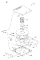
- FIG. 1 is an exploded perspective view showing an example configuration of a magnetic tape cartridge according to an embodiment of the present disclosure.
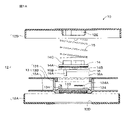
- FIG. 1A is an exploded side sectional view showing an example of the configuration of a magnetic tape cartridge according to an embodiment of the present disclosure;
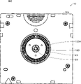
- FIG. 2 is a plan view showing an example of the configuration of the lower surface side of the magnetic tape cartridge according to one embodiment of the present disclosure.
- FIG. 3A is a plan view showing an example of the configuration of the spindle.
- FIG. 3B is an exploded cross-sectional view showing an example of the configuration of the spindle.
- FIG. 4 is a cross-sectional view showing an example of the configuration of the reel.
- 5 is a plan view showing an enlarged part of FIG. 2.
- FIG. 6 is a cross-sectional view showing an enlarged part of FIG.
- FIG. 7A is a plan view showing an example of the configuration of a leaf spring
- FIG. 7B is a cross-sectional view taken along line VIIB--VIIB of FIG. 7A.
- FIG. 8 is a block diagram showing an example of the configuration of the cartridge memory.
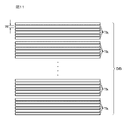
- FIG. 9 is a cross-sectional view showing an example of the configuration of a magnetic tape.
- FIG. 10 is a schematic diagram showing an example layout of data bands and servo bands.
- FIG. 11 is an enlarged view showing an example of the configuration of the data band.
- FIG. 12 is an enlarged view showing an example of the configuration of the servo band.
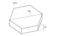
- FIG. 13 is a perspective view showing an example of the shape of particles.
- FIG. 10 is a schematic diagram showing an example layout of data bands and servo bands.
- FIG. 11 is an enlarged view showing an example of the configuration of the data band.
- FIG. 12 is an
- FIG. 14 is a diagram showing an example of a TEM photograph of the magnetic layer.
- FIG. 15 is a diagram showing an example of a TEM photograph of the magnetic layer.
- FIG. 16 is a diagram showing an example of an AFM image of the magnetic surface of the magnetic tape.
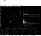
- FIG. 17 is a diagram showing analysis results of projections by AFM.
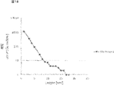
- FIG. 18 is a diagram showing the height distribution of protrusions obtained by AFM.
- FIG. 19 is a diagram showing an example of an FE-SEM image of the magnetic surface of the magnetic tape.
- FIG. 20 is a diagram showing an example of a binarized image of the magnetic surface of the magnetic tape.
- FIG. 21 is a diagram showing a composite image of an AFM image and an FE-SEM image.
- FIG. 21 is a diagram showing a composite image of an AFM image and an FE-SEM image.
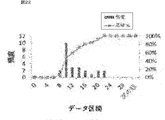
- FIG. 22 is a diagram showing a cumulative frequency distribution of protrusion heights.
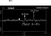
- FIG. 23 is a diagram showing the cross-sectional profile acquisition position (Line 1) in the composite image.
- FIG. 24 is a diagram showing a cross-sectional profile acquired at Line 1 shown in FIG.
- FIG. 1 is an exploded perspective view showing an example configuration of a magnetic tape cartridge 10 (hereinafter simply referred to as "cartridge 10") according to an embodiment of the present disclosure.
- FIG. 1A is an exploded side cross-sectional view of cartridge 10 according to one embodiment of the present disclosure.
- FIG. 2 is a plan view showing an example of the configuration of the bottom side of the cartridge 10 according to one embodiment of the present disclosure.
- the cartridge 10 is a one-reel type cartridge, and includes a cartridge case 12, a reel 13 on which a magnetic tape MT as a tape-shaped magnetic recording medium is wound, and a reel for locking the rotation of the reel 13.
- a door spring 18 for biasing to the closed position, a write protect 19 for preventing erroneous erasure, a cartridge memory 11, a metal plate 22 and a leaf spring 23 are provided.
- the cartridge case 12 is composed of a lower shell 12A and an upper shell 12B.
- An opening 12D is provided in the central portion of the lower shell 12A.
- the tape outlet 12C is provided across the lower shell 12A and the upper shell 12B.
- a leader tape LT is connected to the outer edge of the magnetic tape MT.
- a leader pin 20 is provided at the tip of the leader tape LT.
- the cartridge 10 has a first major surface, a second major surface opposite the first surface, and side surfaces between the peripheries of the first and second surfaces.
- the first main surface and the second main surface have a substantially square shape.
- the first main surface is a surface provided with an opening 12D for chucking the reel 13 by a spindle of a drive (recording/reproducing device).
- the first main surface side of the cartridge 10 will be referred to as the bottom, and the second main surface side of the cartridge 10 will be referred to as the top.
- a reel lock mechanism is provided inside the reel hub 13A to prevent rotation of the tape reel when the tape cartridge 1 is not in use.
- the reel lock mechanism has a plurality of gear forming walls 134 erected on the upper surface of the bottom wall 133 of the reel hub 13A and a gear portion 134A formed on the upper surface of the gear forming wall 134.
- a reel lock 14 having mating teeth (not shown), a spider 16 for releasing the engagement between the gear forming wall 134 and the reel lock 14, and a reel lock provided between the inner surface of the upper shell 12B and the upper surface of the reel lock 14. and a reel spring 15 which is mounted.
- the reel spring 15 is a coil spring and urges the reel 13 toward the lower shell 12A via the reel lock 14. As shown in FIG.
- the gear forming wall 134 has an arc shape and is formed on the upper surface of the bottom wall 133 of the reel hub 13A at three equal intervals on the same circumference around the axis of the reel hub 13A.
- the engaging tooth 14A of the reel lock 14 facing the gear portion 134A of the gear forming wall 134 is formed in an annular shape on the lower surface of the reel lock 14, and receives the reel spring 15 and always engages with the gear portion 134A. is energized by A fitting projection 14C is formed on the upper surface of the reel lock 14, and a fitting recess 12E is formed in the substantially central portion of the inner surface of the upper shell 2 to fit the fitting projection 14C. .
- the spider 16 has a substantially triangular shape and is arranged between the bottom wall 133 of the reel hub 13A and the reel lock 14.
- a total of three legs 16A protrude downward from near the apexes of the generally triangular shape on the lower surface of the spider 16. These legs extend downward from the bottom wall of the reel hub 13A when the cartridge is not used. It is positioned between the gears of the chucking gear through an insertion hole formed at 133 .
- each leg 16A of the spider 16 is pushed upward by a reel rotation drive shaft of a tape drive device that engages with a reel gear (reel gear 133A, which will be described later). to the unlocked position. It is configured to be rotatable with respect to the reel lock 14 together with the tape reel 5 .
- a supporting surface 16B is provided at approximately the center of the upper surface of the spider 16 for supporting a sliding contact portion 14B having an arcuate cross-section and projecting from approximately the center of the lower surface of the reel lock 14 .
- the cartridge 10 may be a magnetic tape cartridge conforming to the LTO (Linear Tape-Open) standard, or may be a magnetic tape cartridge conforming to a standard different from the LTO standard.
- LTO Linear Tape-Open
- FIG. 3A is a plan view showing an example of the configuration of the spindle 101.
- FIG. 3B is an exploded cross-sectional view showing an example of the configuration of the spindle 101.
- FIG. A spindle 101 is provided in a general drive. The spindle 101 is configured to be able to chuck the cartridge 10 having the above configuration.
- the spindle 101 includes a disc portion 102 , a shaft 103 , a magnet 104 , a magnet fixing jig 105 and screws 106 .
- Shaft 103 is supported by bearings 107 .
- the disc portion 102 has a drive gear 102A.
- the drive gear 102A is provided on the upper surface of the disk portion 102. As shown in FIG.
- the drive gear 102A has an annular shape centered on the rotation axis of the disc portion 102 when viewed from above in a direction perpendicular to the upper surface of the disc portion 102 .
- the shaft 103 rotates the disc portion 102 .
- the disc portion 102 is fixed to the upper end of the shaft 103 .
- the shaft 103 has electrical conductivity.
- the shaft 103 is made of, for example, metal.
- Shaft 103 is grounded. Shaft 103 may be grounded via a bearing.
- the magnet 104 is provided inside the drive gear 102A in plan view from a direction perpendicular to the upper surface of the disc portion 102.
- the magnet 104 has a disc shape with a through hole in the center.
- the magnet fixing jig 105 is for fixing the magnet 104 to a prescribed position on the upper surface of the disc portion 102 .
- the magnet fixture 105 has a hole 105A.
- the magnet fixing jig 105 may be made of metal, or may be made of synthetic resin.
- the screw 106 is for fixing the magnet fixing jig 105 to the upper surface of the disc portion 102 .
- the screw 106 is fitted into a screw hole (not shown) provided at the upper end of the shaft 103 via the hole 105A of the magnet fixing jig.
- the screw 106 is conductive, and the screw 106 and the shaft 103 are electrically connected.
- the screw 106 is made of metal or the like, for example.
- the screw 106 is an example of a fixing member (conductive portion) provided on the spindle 101 .
- the screw 106 is provided on the rotating shaft of the disc portion 102 in plan view from a direction perpendicular to the upper surface of the disc portion 102 .
- FIG. 4 is a cross-sectional view showing an example of the configuration of the reel 13.
- FIG. 5 is a plan view showing an enlarged part of FIG. 2.
- FIG. The reel 13 is for winding the magnetic tape MT.
- the reel 13 has a reel hub 13A and a flange 132 .
- the reel 13 has conductivity. Specifically, only reel hub 13A of reel hub 13A and flange 13B may be conductive, or both reel hub 13A and flange 13B may be conductive.
- the upper limit of the surface resistivity of the reel 13 is preferably 1 ⁇ 10 6 ⁇ /sq. It is below.
- the lower limit of the surface resistivity of the reel 13 is preferably 1 ⁇ 10 4 ⁇ /sq. That's it.
- the surface resistivity of the reel 13 means the surface resistance of the reel hub 13A.
- the upper limit of the surface resistivity of the reel 13 is 1 ⁇ 10 6 ⁇ /sq.
- a conductive bus can be formed from the magnetic tape MT to the leaf spring 23 during running. Therefore, charging of the magnetic tape MT during running can be suppressed.
- the surface resistivity of the reel 13 is too low, if discharge occurs on the magnetic surface side in the drive, an excessive current will flow from the magnetic surface to the element of the recording/reproducing head, which may lead to destruction of the element.
- the lower limit is 1 ⁇ 10 4 ⁇ /sq. It is preferable that it is above.
- the surface resistivity of the above reel 13 is measured as follows.
- the surface resistivity of the surface of the flange 132 facing the flange 13B is measured according to ASTM D257, and the measurement result is taken as the surface resistivity of the reel 13.
- the reel 13 contains a synthetic resin and a conductive material.
- the reel 13 may further contain known additives such as antioxidants and flame retardants.
- Synthetic resins include, for example, acrylonitrile-butadiene-styrene copolymer resin (ABS resin) or polyacetal (POM) resin.
- the conductive material includes, for example, at least one of a conductive filler and a conductive polymer.
- the conductive material is preferably dispersed in a synthetic resin.
- Examples of the shape of the conductive filler include spherical, ellipsoidal, needle-like, plate-like, scale-like, tube-like, wire-like, rod-like (rod-like), fibrous, and irregular shapes, and particularly these. is not limited to In addition, only one shape of the conductive filler may be used, or two or more shapes of the conductive filler may be used in combination.
- the conductive fillers include, for example, at least one of carbon-based fillers, metal-based fillers, metal oxide-based fillers, and metal coating-based fillers.
- metals are defined to include semimetals.
- Carbon-based fillers include, for example, carbon black (e.g., ketjen black, acetylene black, etc.), porous carbon, carbon fibers (e.g., PAN-based, pitch-based, etc.), carbon nanofibers, fullerene, graphene, vapor-grown carbon fibers (VGCF ), carbon nanotubes (eg, SWCNTs, MWCNTs, etc.), carbon microcoils, and carbon nanohorns.
- carbon black e.g., ketjen black, acetylene black, etc.
- porous carbon e.g., carbon fibers (e.g., PAN-based, pitch-based, etc.)
- carbon nanofibers fullerene
- graphene graphene
- VGCF vapor-grown carbon fibers
- carbon nanotubes eg, SWCNTs, MWCNTs, etc.
- carbon microcoils e.g., carbon microcoils, and carbon nanohorns.
- Metallic fillers include, for example, copper, silver, gold, platinum, palladium, nickel, tin, cobalt, rhodium, iridium, iron, ruthenium, osmium, manganese, molybdenum, tungsten, niobium, tantalum, titanium, bismuth, antimony and lead. at least one of
- Metal oxide fillers include, for example, indium tin oxide (ITO), zinc oxide, indium oxide, antimony-added tin oxide, fluorine-added tin oxide, aluminum-added zinc oxide, gallium-added zinc oxide, silicon-added zinc oxide, and zinc oxide.
- ITO indium tin oxide
- zinc oxide zinc oxide
- indium oxide antimony-added tin oxide
- fluorine-added tin oxide aluminum-added zinc oxide
- gallium-added zinc oxide gallium-added zinc oxide
- silicon-added zinc oxide silicon-added zinc oxide
- zinc oxide - tin oxide, indium oxide - tin oxide or zinc oxide - indium oxide - magnesium oxide.
- a metal-coated filler is a base filler coated with a metal.
- Base fillers are, for example, mica, glass beads, glass fibres, carbon fibres, calcium carbonate, zinc oxide or titanium oxide.
- the metal that coats the base filler contains at least one of Ni and Al, for example.
- the conductive polymer includes, for example, at least one of polyethylenedioxythiophene/polystyrenesulfonic acid (PEDOT/PSS), polyaniline, polyacetylene and polypyrrole.
- PEDOT/PSS polyethylenedioxythiophene/polystyrenesulfonic acid
- polyaniline polyaniline
- polyacetylene polyacetylene and polypyrrole.
- the reel hub 13A has a hub 131, a flange 132 and a bottom wall 133. As shown in FIG.
- the hub 131 is for winding the magnetic tape MT. One end of the magnetic tape MT is fixed to the hub 131 .
- the hub 131 has a cylindrical shape with one end closed. Hub 131 and flange 132 may have a one-piece construction, such as by injection molding.
- a bottom wall 133 is provided at the lower end of the hub 131 .
- a bottom wall 133 closes the lower end of the hub 131 .
- the bottom wall 133 has a reel gear 133A.
- the reel gear 133A meshes with the drive gear 102A on the drive side when the cartridge 10 is chucked by the spindle 101.
- the reel gear 133A is provided along the outer periphery of the lower surface of the bottom wall 133.
- the reel gear 133A has an annular shape centered on the rotation axis of the reel hub 13A.
- the reel gear 133A is arranged to face the opening 12D on the bottom surface of the cartridge case 12. As shown in FIG.
- the flange 13B and the flange 132 cover both widthwise ends of the magnetic tape MT wound around the hub 131 .
- the flanges 13B and 132 are supported by the hub 131 so that their main surfaces face each other with a specified distance therebetween.
- the flange 13B protrudes from the upper end of the outer peripheral surface of the hub 131 in the radial direction of the hub 131 .
- the flange 132 protrudes in the radial direction of the hub 131 from the lower end of the outer peripheral surface of the hub 131 .
- Flange 13B and flange 132 have a disc shape.
- the flange 13B is fixed, for example, to the upper end of the outer peripheral surface of the hub 131 by adhesion, welding (for example, ultrasonic welding), or the like.
- Flange 132 is, for example, integrally formed with hub 131 as described above.
- the metal plate 22 is magnetically attracted to the magnet 104 when the cartridge 10 is chucked by the spindle 101 .
- the metal plate 22 has an annular shape.
- the metal plate 22 is provided on the inner peripheral side of the reel gear 2 ⁇ /b>E in plan view from the direction perpendicular to the lower surface of the bottom wall 133 .
- the metal plate 22 is arranged to face the opening 12D in the bottom surface of the cartridge case 12 together with the reel gear 2E.
- the metal plate 22 has a plurality of holes 22A.
- a plurality of protrusions 133B are provided on the bottom surface of the bottom wall 133 .
- Each of the plurality of convex portions 133B is provided at a position corresponding to each hole portion 22A.
- the plurality of protrusions 133B are formed integrally with the bottom wall 133 by, for example, injection molding. Each projection 133B is inserted into each of the plurality of holes 22A. Thereby, the metal plate 22 is fixed to the bottom surface of the bottom wall 133 .
- the reel hub 13A and the metal plate 22 may be integrally molded by insert molding.
- FIG. 6 is a cross-sectional view taken along line VI-VI of FIG.
- FIG. 7A is a plan view showing an example of the configuration of the leaf spring 23.
- FIG. 7B is a cross-sectional view taken along line VIIB--VIIB of FIG. 7A.
- the plate spring 23 is configured to be able to bias the screw 106 provided on the spindle 101 when the reel gear 133A is meshed with the drive gear 102A.
- the leaf spring 23 is an example of a conductive elastic member.
- the leaf spring 23 is provided in the opening of the metal plate 22 in plan view from a direction perpendicular to the lower surface of the bottom wall 133 .
- the leaf spring 23 is provided on the rotating shaft of the reel 13, that is, on the rotating shaft of the reel gear 133A.
- the plate spring 23 includes a ring portion 23A and a projecting portion 23B.
- the ring portion 23A is fixed to the lower surface of the bottom wall 133.
- the ring portion 23A has a plurality of holes 23C.
- the lower surface of the bottom wall 133 is provided with a plurality of protrusions 133C.
- Each of the plurality of convex portions 133C is provided at a position corresponding to each hole portion 23C.
- the plurality of protrusions 133C are formed integrally with the bottom wall 133 by, for example, injection molding.
- Each projection 133C is inserted into each of the plurality of holes 23C. Thereby, the leaf spring 23 is fixed to the lower surface of the bottom wall 133 .
- the top of each projection 133C may be crimped.
- the protrusion 23B is biased by the screw 106 provided on the spindle 101 and bends.
- the projecting portion 23B extends downward from a portion of the inner circumference of the ring portion 23A, that is, in a direction away from the lower surface of the bottom wall 133.
- the leaf spring 23 is provided on the lower surface of the bottom wall 133 , the protruding portion 23B protrudes from the lower surface of the bottom wall 133 .
- the leaf spring 23 is positioned inside the inner circumference of the ring portion 23A in plan view from a direction perpendicular to the lower surface of the bottom wall 133 .
- a cartridge memory 11 is provided near one corner of the cartridge 10 .
- the cartridge memory 11 faces the reader/writer of the drive.
- the cartridge memory 11 communicates with a drive, more specifically, a reader/writer, according to a wireless communication standard conforming to the LTO standard.
- FIG. 8 is a block diagram showing an example of the configuration of the cartridge memory 11.
- the cartridge memory 11 includes an antenna coil (communication unit) 31 that communicates with the reader/writer according to a specified communication standard, and a rectifier that generates power by using induced electromotive force and rectifies the radio waves received by the antenna coil 31.
- antenna coil communication unit
- rectifier that generates power by using induced electromotive force and rectifies the radio waves received by the antenna coil 31.
- the cartridge memory 11 also includes a capacitor 37 connected in parallel to the antenna coil 31, and the antenna coil 31 and the capacitor 37 constitute a resonance circuit.
- the memory 36 stores information related to the cartridge 10 and the like.
- the memory 36 is a non-volatile memory (NVM).
- the storage capacity of memory 36 is preferably about 32 KB or greater.
- the memory 36 has a first storage area 36A and a second storage area 36B.
- the first storage area 36A corresponds to, for example, the storage area of a cartridge memory of a magnetic tape standard before the specified generation (for example, the LTO standard before LTO8), and the magnetic tape standard before the specified generation (for example, the LTO standard before LTO8).
- the information conforming to the magnetic tape standards before the prescribed generation includes, for example, the manufacturing information of the cartridge 10 (for example, the unique number of the cartridge 10) and the usage history of the cartridge 10 (for example, the withdrawal of the magnetic tape MT). number of times (Thread Count), etc.).
- the second storage area 36B corresponds to an extended storage area for the storage area of the cartridge memory of the magnetic tape standard before the specified generation (for example, the LTO standard before LTO8).
- the second storage area 36B is an area for storing additional information.
- the additional information means, for example, information related to the cartridge 10 that is not defined by the magnetic tape standards before the specified generation (for example, the LTO standards before LTO8).
- the additional information includes, for example, at least one selected from the group consisting of tension adjustment information, management ledger data, index information, thumbnail information, and the like.
- the tension adjustment information is information for adjusting the tension applied to the magnetic tape MT in the longitudinal direction.
- the tension adjustment information is, for example, selected from the group consisting of information obtained by intermittently measuring the width between servo bands in the longitudinal direction of the magnetic tape MT, drive tension information, drive temperature and humidity information, and the like. and at least one type of information. These pieces of information may be managed in cooperation with information about the usage status of the cartridge 10 and the like. It is preferable that the tension adjustment information be acquired during or before data recording on the magnetic tape MT.
- the drive tension information means information on the tension applied to the magnetic tape MT in the longitudinal direction.
- the management ledger data is data that includes at least one of the data file capacity, creation date, editing date, storage location, etc. of the data file recorded on the magnetic tape MT.
- the index information is metadata or the like for searching the contents of the data file.
- the thumbnail information is thumbnails of moving images or still images stored on the magnetic tape MT.
- the memory 36 may have multiple banks. In this case, part of the plurality of banks may constitute the first storage area 36A, and the remaining banks may constitute the second storage area 36B.
- the antenna coil 31 induces an induced voltage by electromagnetic induction.
- the controller 35 communicates with the drive via the antenna coil 31 according to a prescribed communication standard. Specifically, for example, mutual authentication, command transmission/reception, or data exchange is performed.
- the controller 35 stores information received from the drive via the antenna coil 31 in the memory 36.
- the tension adjustment information received from the drive via the antenna coil 31 is stored in the second storage area 36B of the memory 36.
- FIG. The controller 35 reads information from the memory 36 and transmits it to the drive via the antenna coil 31 in response to a request from the drive.
- the tension adjustment information is read from the second storage area 36B of the memory 36 and transmitted to the drive via the antenna coil 31 in response to a request from the drive.
- FIG. 9 is a cross-sectional view showing an example of the configuration of the magnetic tape MT.
- the magnetic tape MT includes a long substrate 41, an underlayer 42 provided on one main surface (first main surface) of the substrate 41, a magnetic layer 43 provided on the underlayer 42, and a back layer 44 provided on the other main surface (second main surface) of the substrate 41 .
- the base layer 42 and the back layer 44 are provided as required, and may be omitted.
- the magnetic tape MT may be a perpendicular recording magnetic recording medium or a longitudinal recording magnetic recording medium.
- the magnetic tape MT preferably contains a lubricant from the viewpoint of improving running properties. At least one of the underlayer 42 and the magnetic layer 43 may contain the lubricant.
- the magnetic tape MT may comply with the LTO standard, or may comply with a standard different from the LTO standard.
- the width of the magnetic tape MT may be 1/2 inch or wider than 1/2 inch. If the magnetic tape MT complies with the LTO standard, the width of the magnetic tape MT is 1/2 inch.
- the magnetic tape MT may have a configuration in which the width of the magnetic tape MT can be kept constant or substantially constant by adjusting the tension applied in the longitudinal direction of the magnetic tape MT during running by means of a drive.
- a TMR element is preferably used for reproducing the magnetic tape MT.
- the magnetic tape MT has a long shape and runs in the longitudinal direction during recording and reproduction.
- the magnetic tape MT is preferably used in a drive having a ring head as a recording head.
- the magnetic tape MT is preferably used in a drive configured to record data with a data track width of 1500 nm or less or 1000 nm or less.
- the base 41 is a non-magnetic support that supports the underlayer 42 and the magnetic layer 43 .
- the substrate 41 has a long film shape.
- the upper limit of the average thickness of the substrate 41 is, for example, 4.4 ⁇ m or less, preferably 4.2 ⁇ m or less, more preferably 4.0 ⁇ m or less, still more preferably 3.8 ⁇ m or less, particularly preferably 3.6 ⁇ m or less, most preferably 3.6 ⁇ m or less. is 3.4 ⁇ m or less.
- the recording capacity that can be recorded in one data cartridge can be made higher than that of a general magnetic tape.
- the lower limit of the average thickness of the substrate 41 is preferably 3 ⁇ m or more, more preferably 3.2 ⁇ m or more. When the lower limit of the average thickness of the substrate 41 is 3 ⁇ m or more, a decrease in the strength of the substrate 41 can be suppressed.
- the average thickness of the substrate 41 is obtained as follows. First, prepare a magnetic tape MT and cut it into a length of 250 mm to prepare a sample. Subsequently, the layers of the sample other than the substrate 41 (that is, the underlayer 42, the magnetic layer 43 and the back layer 44) are removed with a solvent such as MEK (methyl ethyl ketone) or dilute hydrochloric acid. Next, using a Mitutoyo laser hologram (LGH-110C) as a measuring device, the thickness of the sample (substrate 41) was measured at five positions, and the measured values were simply averaged (arithmetic average). Then, the average thickness of the substrate 41 is calculated. It is assumed that the measurement position is randomly selected from the sample.
- a solvent such as MEK (methyl ethyl ketone) or dilute hydrochloric acid.
- the substrate 41 contains, for example, at least one of polyesters, polyolefins, cellulose derivatives, vinyl resins, and other polymer resins.
- the substrate 41 contains two or more of the above materials, the two or more materials may be mixed, copolymerized, or laminated.
- the substrate 41 preferably contains polyesters among the polymer resins described above.
- the longitudinal Young's modulus of the base 41 can be reduced to preferably 2.5 GPa or more and 7.8 GPa or less, more preferably 3.0 GPa or more and 7.0 GPa or less. Therefore, it is particularly easy to control the width of the magnetic tape MT to be constant or substantially constant by adjusting the tension in the longitudinal direction of the magnetic tape MT during running with the drive. A method of measuring the Young's modulus in the longitudinal direction of the substrate 41 will be described later.
- Polyesters include, for example, PET (polyethylene terephthalate), PEN (polyethylene naphthalate), PBT (polybutylene terephthalate), PBN (polybutylene naphthalate), PCT (polycyclohexylene dimethylene terephthalate), PEB (polyethylene-p- oxybenzoate) and polyethylene bisphenoxycarboxylate.
- PET polyethylene terephthalate
- PEN polyethylene naphthalate
- PBT polybutylene terephthalate
- PBN polybutylene naphthalate
- PCT polycyclohexylene dimethylene terephthalate
- PEB polyethylene-p- oxybenzoate
- polyethylene bisphenoxycarboxylate polyethylene bisphenoxycarboxylate.
- the substrate 41 contains two or more polyesters
- the two or more polyesters may be mixed, copolymerized, or laminated. At least one of the terminals and side chains of the polyesters may be modified.
- polyesters in the substrate 41 can be confirmed, for example, as follows. First, a magnetic tape MT is prepared in the same manner as in the method for measuring the average thickness of the substrate 41, cut into a length of 250 mm to prepare a sample, and then layers other than the substrate 41 are removed from the sample. Next, an IR spectrum of the sample (substrate 41) is obtained by infrared absorption spectrometry (IR). Based on this IR spectrum, it can be confirmed that the substrate 41 contains polyesters.
- IR infrared absorption spectrometry
- Polyolefins include, for example, at least one of PE (polyethylene) and PP (polypropylene).
- Cellulose derivatives include, for example, at least one of cellulose diacetate, cellulose triacetate, CAB (cellulose acetate butyrate) and CAP (cellulose acetate propionate).
- Vinyl-based resins include, for example, at least one of PVC (polyvinyl chloride) and PVDC (polyvinylidene chloride).
- PA polyamide, nylon
- aromatic PA aromatic PA
- PAI polyamideimide
- aromatic PAI aromatic polyamideimide
- PBO polybenzoxazole, e.g. Zylon®
- polyether PEK (polyetherketone), PEEK (polyetheretherketone), polyetherester, PES (polyethersulfone) , PEI (polyetherimide), PSF (polysulfone), PPS (polyphenylene sulfide), PC (polycarbonate), PAR (polyarylate) and PU (polyurethane).
- PEK polyetherketone
- PEEK polyetheretherketone
- PES polyethersulfone
- PEI polyetherimide
- PSF polysulfone
- PPS polyphenylene sulfide
- PC polycarbonate
- PAR polyarylate
- PU polyurethane
- the substrate 41 may be biaxially stretched in the longitudinal direction and the width direction.
- the polymer resin contained in the substrate 41 is preferably oriented obliquely with respect to the width direction of the substrate 41 .
- the magnetic layer 43 is a recording layer for recording signals by magnetization patterns.
- the magnetic layer 43 may be a perpendicular recording type recording layer or a longitudinal recording type recording layer.
- the magnetic layer 43 contains, for example, magnetic powder, binder and carbon.
- the magnetic layer 43 may further contain at least one additive selected from lubricants, antistatic agents, abrasives, hardeners, rust preventives, non-magnetic reinforcing particles, and the like, if necessary.
- the magnetic layer 43 has a large number of protrusions 43A made of carbon protruding from the magnetic surface on the magnetic surface.
- the magnetic layer 43 may have a large number of protrusions 43A made of an abrasive (for example, alumina) protruding from the magnetic surface on the magnetic surface.
- abrasive for example, alumina
- the protrusion 43A made of carbon protruding from the magnetic surface is referred to as "carbon protrusion 43A”
- alumina protrusion 43A the protrusion 43A made of alumina protruding from the magnetic surface
- the magnetic layer 43 may have a plurality of servo bands SB and a plurality of data bands DB in advance, as shown in FIG.
- a plurality of servo bands SB are provided at regular intervals in the width direction of the magnetic tape MT.
- a data band DB is provided between adjacent servo bands SB.
- the servo band SB is for guiding the head 56 (specifically, the servo read heads 56A and 56B) when recording or reproducing data.
- a servo pattern (servo signal) for tracking control of the head 56 is written in advance in the servo band SB. User data is recorded in the data band DB.
- the lower limit of the ratio R S of the total area S SB of the plurality of servo bands SB to the surface area S of the magnetic layer 43 is preferably 0.8% or more from the viewpoint of ensuring 5 or more servo bands SB. be.
- the ratio R S of the total area S SB of the plurality of servo bands SB to the area S of the entire surface of the magnetic layer 43 is obtained as follows.
- the magnetic tape MT was developed using a ferricolloid developer (manufactured by Sigma High Chemical Co., Ltd., Sigmamarker Q), and then the developed magnetic tape MT was observed with an optical microscope to determine the servo band width W SB and the servo band SB. Measure the number of Next, the ratio R S is obtained from the following formula.
- Ratio R S [%] (((servo band width W SB ) ⁇ (number of servo bands SB))/(width of magnetic tape MT)) ⁇ 100
- the number of servo bands SB is, for example, 5+4n (where n is an integer equal to or greater than 0) or more.
- the number of servo bands SB is preferably 5 or more, more preferably 9 or more.
- the upper limit of the number of servo bands SB is not particularly limited, it is, for example, 33 or less.
- the number of servo bands SB is obtained in the same manner as the method of calculating the ratio RS described above.
- the upper limit of the servo band width WSB is preferably 95 ⁇ m or less, more preferably 60 ⁇ m or less, and even more preferably 30 ⁇ m or less, from the viewpoint of ensuring a high recording capacity.
- the lower limit of the servo bandwidth W SB is preferably 10 ⁇ m or more. A head 56 capable of reading servo signals with a servo bandwidth W SB of less than 10 ⁇ m is difficult to manufacture.
- the width of the servo band width WSB is obtained in the same manner as the method of calculating the ratio RS described above.
- the magnetic layer 43 is configured to form a plurality of data tracks Tk in the data band DB, as shown in FIG.
- the upper limit of the data track width W is preferably 1500 nm or less, more preferably 1000 nm or less, even more preferably 800 nm or less, and particularly preferably 600 nm or less, from the viewpoint of improving the track recording density and ensuring a high recording capacity.
- the lower limit of the data track width W is preferably 20 nm or more.
- the magnetic layer 43 can record data such that the minimum value L of the distance between magnetization reversals is preferably 40 nm or less, more preferably 36 nm or less, and even more preferably 32 nm or less. It is configured. Considering the magnetic grain size, the lower limit of the minimum value L of the distance between magnetization reversals is preferably 20 nm or more.
- the data track width W is obtained as follows.
- a magnetic tape MT having data recorded over its entire surface is prepared, and the data recording pattern of the data band DB portion of the magnetic layer 43 is observed using a magnetic force microscope (MFM) to obtain an MFM image.
- MFM magnetic force microscope
- Dimension3100 manufactured by Digital Instruments and its analysis software are used as MFM.
- the track width is measured at 10 points from the three obtained MFM images, and the average value (which is a simple average) is obtained.
- the average value is the data track width W.
- FIG. The measurement conditions for the above MFM are sweep speed: 1 Hz, chip used: MFMR-20, lift height: 20 nm, correction: Flatten order 3.
- the minimum value L of the distance between magnetization reversals is obtained as follows.
- a magnetic tape MT having data recorded over its entire surface is prepared, and the data recording pattern of the data band DB portion of the magnetic layer 43 is observed using a magnetic force microscope (MFM) to obtain an MFM image.
- MFM magnetic force microscope
- Dimension3100 manufactured by Digital Instruments and its analysis software are used as MFM.
- bit distances are measured from the two-dimensional unevenness chart of the recording pattern of the obtained MFM image.
- the bit-to-bit distance is measured using analysis software attached to Dimension3100.
- the minimum value L of the distance between magnetization reversals is defined as the greatest common divisor of the 50 measured inter-bit distances.
- the measurement conditions are sweep speed: 1 Hz, chip used: MFMR-20, lift height: 20 nm, correction: Flatten order 3.
- a servo pattern is a magnetized region, which is formed by magnetizing a specific region of the magnetic layer 43 in a specific direction with a servo write head when manufacturing the magnetic tape.
- a region of the servo band SB in which no servo pattern is formed (hereinafter referred to as a “non-pattern region”) may be a magnetized region in which the magnetic layer 43 is magnetized, or the magnetic layer 43 is not magnetized. It may be a non-magnetized region.
- the non-pattern area is a magnetized area
- the servo pattern formation area and the non-pattern area are magnetized in different directions (for example, opposite directions).
- the servo band SB is formed with a servo pattern consisting of a plurality of servo stripes (linear magnetized regions) 113 inclined with respect to the width direction of the magnetic tape MT, as shown in FIG.
- the servo band SB includes a plurality of servo frames 110.
- Each servo frame 110 consists of 18 servo stripes 113 .
- each servo frame 110 is composed of servo sub-frame 1 (111) and servo sub-frame 2 (112).
- Servo subframe 1 (111) consists of A burst 111A and B burst 111B.
- the B burst 111B is arranged adjacent to the A burst 111A.
- the A burst 111A includes five servo stripes 113 that are inclined at a predetermined angle ⁇ with respect to the width direction of the magnetic tape MT and are formed at predetermined intervals. In FIG. 12, these five servo stripes 113 are denoted by A 1 , A 2 , A 3 , A 4 , and A 5 from EOT (End Of Tape) to BOT (Beginning Of Tape) of the magnetic tape MT. are shown.
- the B burst 111B includes five servo pulses 63 which are inclined at a predetermined angle ⁇ with respect to the width direction of the magnetic tape MT and formed at predetermined intervals.
- these five servo stripes 113 are indicated by B 1 , B 2 , B 3 , B 4 and B 5 from EOT to BOT of the magnetic tape MT.
- the servo stripes 113 of the B burst 111B are slanted in the opposite direction to the servo stripes 113 of the A burst 111A. That is, the servo stripes 113 of the A burst 111A and the servo stripes 113 of the B burst 111B are arranged in an inverted V shape.
- Servo subframe 2 (112) consists of a C burst 112C and a D burst 112D.
- D burst 112D is located adjacent to C burst 112C.
- the C burst 112C has four servo stripes 113 which are inclined at a predetermined angle ⁇ with respect to the tape width direction and are formed at regular intervals. In FIG. 12, these four servo stripes 113 are denoted by C 1 , C 2 , C 3 and C 4 from EOT to BOT of the magnetic tape MT.
- the D burst 112D includes four servo pulses 63 which are inclined at a predetermined angle ⁇ with respect to the tape width direction and formed at predetermined intervals.
- these four servo stripes 113 are denoted by D 1 , D 2 , D 3 and D 4 from EOT to BOT of the magnetic tape MT.
- the servo stripes 113 of the D burst 112D are slanted in the opposite direction to the servo stripes 113 of the C burst 112C. That is, the servo stripes 113 of the C burst 112C and the servo stripes 113 of the D burst 112D are arranged in an inverted V shape.
- the predetermined angle ⁇ of the servo stripe 113 in the A burst 111A, B burst 111B, C burst 112C, and D burst 112D is, for example, 11° or more and 40° or less, preferably 11° or more and 36° or less, more preferably 11° or more and 25°. ° or less, and even more preferably 17° or more and 25° or less.
- a servo pattern may be a shape comprising two parallel lines.
- the servo patterns (that is, the plurality of servo stripes 113) are preferably arranged linearly in the longitudinal direction of the magnetic tape MT. That is, the servo band SB preferably has a straight shape in the longitudinal direction of the magnetic tape MT.
- the upper limit of the average thickness of the magnetic layer 43 is preferably 80 nm or less, more preferably 70 nm or less, still more preferably 60 nm or less, and particularly preferably 50 nm or less. If the upper limit of the average thickness of the magnetic layer 43 is 80 nm or less, the influence of the demagnetizing field can be reduced when a ring head is used as the recording head, so that even better electromagnetic conversion characteristics can be obtained.
- the lower limit of the average thickness of the magnetic layer 43 is preferably 35 nm or more. If the lower limit of the average thickness of the magnetic layer 43 is 35 nm or more, the output can be ensured when an MR head is used as the reproducing head, so that even better electromagnetic conversion characteristics can be obtained.
- the average thickness of the magnetic layer 43 is obtained as follows. First, the magnetic tape MT accommodated in the cartridge 10 is unwound, and the magnetic tape MT and the leader tape LT are unwound in the longitudinal direction (specifically, from one end on the leader tape LT side to the other end on the opposite side). The magnetic tape MT is cut at three positions of 10 m, 30 m, and 50 m in the direction) to prepare three samples. Subsequently, each sample is processed by the FIB method or the like to be thinned. When the FIB method is used, a carbon layer and a tungsten layer are formed as protective films as a pretreatment for observing a cross-sectional TEM image, which will be described later.
- the carbon layer is formed on the magnetic layer 43 side surface and the back layer 44 side surface of the magnetic tape MT by vapor deposition, and the tungsten layer is further formed on the magnetic layer 43 side surface by vapor deposition or sputtering.
- the thinning is performed along the length direction (longitudinal direction) of the magnetic tape MT. That is, by the thinning, a cross section parallel to both the longitudinal direction and the thickness direction of the magnetic tape MT is formed.
- the thickness of the magnetic layer 43 is measured at 10 positions of each sliced sample.
- the ten measurement positions of each thinned sample are aligned along the longitudinal direction of the magnetic tape MT.
- the average thickness [nm] of the magnetic layer 43 is obtained by simply averaging (arithmically averaging) the measured values of each thinned sample (thickness of the magnetic layer 43 at 30 points in total).
- the position where the above measurement is performed shall be randomly selected from the test piece.
- Magnetic powder includes a plurality of magnetic particles.
- Magnetic particles are, for example, particles containing metal oxide (hereinafter referred to as “metal oxide particles”).
- the metal oxide particles are, for example, particles containing hexagonal ferrite (hereinafter referred to as “hexagonal ferrite particles”), particles containing epsilon-type iron oxide ( ⁇ iron oxide) (hereinafter referred to as “ ⁇ iron oxide particles”), or Particles containing Co-containing spinel ferrite (hereinafter referred to as “cobalt ferrite particles”).
- the magnetic powder is preferably crystal-oriented preferentially in the direction perpendicular to the magnetic tape MT.
- the vertical direction (thickness direction) of the magnetic tape MT means the thickness direction of the magnetic tape MT in a planar state.
- the hexagonal ferrite particles have, for example, a plate shape such as a hexagonal plate shape or a columnar shape such as a hexagonal columnar shape (where the thickness or height is smaller than the major axis of the plate surface or bottom surface).
- the hexagonal plate shape includes a substantially hexagonal plate shape.
- the hexagonal ferrite preferably contains at least one of Ba, Sr, Pb and Ca, more preferably at least one of Ba and Sr.
- the hexagonal ferrite may in particular be, for example, barium ferrite or strontium ferrite. Barium ferrite may further contain at least one of Sr, Pb and Ca in addition to Ba.
- the strontium ferrite may further contain at least one of Ba, Pb and Ca in addition to Sr.
- hexagonal ferrite has an average composition represented by the general formula MFe 12 O 19 .
- M is, for example, at least one metal selected from Ba, Sr, Pb and Ca, preferably at least one metal selected from Ba and Sr.
- M may be a combination of Ba and one or more metals selected from the group consisting of Sr, Pb and Ca.
- M may be a combination of Sr and one or more metals selected from the group consisting of Ba, Pb and Ca.
- Part of Fe in the above general formula may be substituted with another metal element.
- the average particle size of the magnetic powder is preferably 13 nm or more and 22 nm or less, more preferably 13 nm or more and 19 nm or less, even more preferably 13 nm or more and 18 nm or less, and particularly preferably 14 nm or more and 17 nm. Below, it is most preferably 14 nm or more and 16 nm or less.
- the average particle size of the magnetic powder is 22 nm or less, even better electromagnetic conversion characteristics (for example, SNR) can be obtained in the high recording density magnetic tape MT.
- the average particle size of the magnetic powder is 13 nm or more, the dispersibility of the magnetic powder is further improved, and even better electromagnetic conversion characteristics (for example, SNR) can be obtained.
- the average aspect ratio of the magnetic powder is preferably 1.0 or more and 3.0 or less, more preferably 1.5 or more and 2.8 or less, and even more preferably 1.8. 2.7 or less. If the average aspect ratio of the magnetic powder is within the range of 1.0 or more and 3.0 or less, the aggregation of the magnetic powder can be suppressed. In addition, when the magnetic powder is vertically oriented in the process of forming the magnetic layer 43, the resistance applied to the magnetic powder can be suppressed. Therefore, the perpendicular orientation of the magnetic powder can be improved.
- the average particle size and average aspect ratio of the magnetic powder are obtained as follows.
- the magnetic tape MT to be measured is processed by the FIB method or the like to be thinned.
- a carbon layer and a tungsten layer are formed as protective films as a pretreatment for observing a cross-sectional TEM image, which will be described later.
- the carbon layer is formed on the magnetic layer 43 side surface and the back layer 44 side surface of the magnetic tape MT by vapor deposition, and the tungsten layer is further formed on the magnetic layer 43 side surface by vapor deposition or sputtering. be.
- the thinning is performed along the length direction (longitudinal direction) of the magnetic tape MT. That is, by the thinning, a cross section parallel to both the longitudinal direction and the thickness direction of the magnetic tape MT is formed.
- the above-mentioned cross section of the obtained thin sample was examined with an acceleration voltage of 200 kV and a total magnification of 500,000 times.
- a cross-sectional observation is performed so as to include , and a TEM photograph is taken.
- the number of TEM photographs is prepared so that 50 particles that can measure the plate diameter DB and the plate thickness DA (see FIG. 13) shown below can be extracted.
- the shape of the particles observed in the above TEM photograph is plate-like or column-like (provided that the thickness or height is smaller than the major axis of the plate surface or bottom surface) as shown in FIG.
- the major diameter of the plate surface or bottom surface of the particle is taken as the value of the plate diameter DB.
- the thickness or height of the particles observed in the above TEM photograph is taken as the plate thickness DA value.
- the major axis means the longest diagonal distance.
- the thickness or height of the largest grain is defined as the plate thickness DA.
- 50 particles to be extracted from the TEM photograph taken are selected based on the following criteria. Particles partly protruding outside the field of view of the TEM photograph are not measured, but particles with clear contours and present in isolation are measured. When particles overlap, if the boundary between the two particles is clear and the overall shape of the particle can be determined, each particle is measured as a single particle, but the boundary is not clear and the overall shape of the particle cannot be determined Particles that do not have a shape are not measured as the shape of the particles cannot be determined.
- FIGS. 14 and 15 show examples of TEM photographs.
- the particles indicated by arrows a and d are selected because the plate thickness (thickness or height of the particle) DA of the particle can be clearly identified.
- the plate thickness DA of each of the 50 selected particles is measured.
- the average plate thickness DA ave is obtained by simply averaging (arithmetic mean) the plate thicknesses DA thus obtained.
- the average thickness DA ave is the average grain thickness.
- the plate diameter DB of each magnetic powder is measured.
- 50 particles whose tabular diameter DB of the particles can be clearly confirmed are selected from the photographed TEM photographs. For example, in FIGS.
- particles indicated by arrows b and c are selected because their plate diameter DB can be clearly confirmed.
- the plate diameter DB of each of the 50 selected particles is measured.
- a simple average (arithmetic mean) of the plate diameters DB obtained in this way is obtained to obtain an average plate diameter DB ave .
- the average platelet diameter DB ave is the average particle size.
- the average aspect ratio (DB ave /DA ave ) of the particles is obtained from the average plate thickness DA ave and the average plate diameter DB ave .
- the average particle volume of the magnetic powder is preferably 500 nm 3 or more and 2500 nm 3 or less, more preferably 500 nm 3 or more and 1600 nm 3 or less, still more preferably 500 nm 3 or more and 1500 nm 3 or less, especially It is preferably 600 nm 3 or more and 1200 nm 3 or less, and most preferably 600 nm 3 or more and 1000 nm 3 or less.
- the average particle volume of the magnetic powder is 2500 nm 3 or less, the same effects as when the average particle size of the magnetic powder is 22 nm or less can be obtained.
- the average particle volume of the magnetic powder is 500 nm 3 or more, the same effect as when the average particle size of the magnetic powder is 13 nm or more can be obtained.
- the average particle volume of magnetic powder is determined as follows. First, the average plate thickness DA ave and the average plate diameter DB ave are determined as described above for the method of calculating the average particle size of the magnetic powder. Next, the average volume V of the magnetic powder is obtained by the following formula.
- ⁇ iron oxide particles are hard magnetic particles capable of obtaining a high coercive force even when they are fine particles.
- the ⁇ -iron oxide particles have a spherical shape or have a cubic shape.
- the spherical shape shall include substantially spherical shape.
- the cubic shape includes a substantially cubic shape. Since the ⁇ -iron oxide particles have the above-described shape, when the ⁇ -iron oxide particles are used as the magnetic particles, the magnetic tape MT It is possible to reduce the contact area between the particles in the thickness direction and suppress the aggregation of the particles. Therefore, it is possible to improve the dispersibility of the magnetic powder and obtain even better electromagnetic conversion characteristics (for example, SNR).
- ⁇ -iron oxide particles have a core-shell structure. Specifically, the ⁇ -iron oxide particles are provided with a core portion and a two-layered shell portion provided around the core portion.
- the shell portion having a two-layer structure includes a first shell portion provided on the core portion and a second shell portion provided on the first shell portion.
- the core portion contains ⁇ -iron oxide.
- the ⁇ -iron oxide contained in the core portion preferably has an ⁇ -Fe 2 O 3 crystal as a main phase, more preferably a single-phase ⁇ -Fe 2 O 3 .
- the first shell part covers at least part of the periphery of the core part.
- the first shell portion may partially cover the periphery of the core portion, or may cover the entire periphery of the core portion. From the viewpoint of ensuring sufficient exchange coupling between the core portion and the first shell portion and improving the magnetic properties, it is preferable that the entire surface of the core portion is covered.
- the first shell part is a so-called soft magnetic layer, and includes a soft magnetic material such as ⁇ -Fe, Ni-Fe alloy or Fe-Si-Al alloy.
- ⁇ -Fe may be obtained by reducing ⁇ -iron oxide contained in the core.
- the second shell portion is an oxide film as an antioxidant layer.
- the second shell portion comprises alpha iron oxide, aluminum oxide or silicon oxide.
- ⁇ -iron oxides include, for example, at least one iron oxide selected from Fe 3 O 4 , Fe 2 O 3 and FeO.
- the ⁇ -iron oxide may be obtained by oxidizing the ⁇ -Fe contained in the first shell.
- the ⁇ -iron oxide particles have the first shell portion as described above, the coercive force Hc of the core portion alone is maintained at a large value in order to ensure thermal stability, and the ⁇ -iron oxide particles (core-shell particles) as a whole can be adjusted to a coercive force Hc suitable for recording.
- the ⁇ -iron oxide particles have the second shell portion as described above, the ⁇ -iron oxide particles are exposed to the air during and before the manufacturing process of the magnetic tape MT, and the particle surface is rusted or the like. can be suppressed from deteriorating the properties of the ⁇ -iron oxide particles. Therefore, deterioration of the characteristics of the magnetic tape MT can be suppressed.
- the ⁇ -iron oxide particles may have a shell portion with a single-layer structure.
- the shell portion has the same configuration as the first shell portion.
- the ⁇ -iron oxide particles may contain an additive instead of the core-shell structure, or may have a core-shell structure and contain an additive. In this case, part of the Fe in the ⁇ -iron oxide particles is replaced with the additive.
- the coercive force Hc of the ⁇ -iron oxide particles as a whole can also be adjusted to a coercive force Hc suitable for recording, so that the easiness of recording can be improved.
- the additive is a metal element other than iron, preferably a trivalent metal element, more preferably at least one of Al, Ga and In, still more preferably at least one of Al and Ga.
- the ⁇ -iron oxide containing the additive is ⁇ -Fe 2-x M x O 3 crystals (where M is a metal element other than iron, preferably a trivalent metal element, more preferably Al, Ga and In, even more preferably at least one of Al and Ga.
- M is a metal element other than iron, preferably a trivalent metal element, more preferably Al, Ga and In, even more preferably at least one of Al and Ga.
- x is, for example, 0 ⁇ x ⁇ 1.
- the average particle size of the magnetic powder is preferably 10 nm or more and 20 nm or less, more preferably 10 nm or more and 18 nm or less, even more preferably 10 nm or more and 16 nm or less, and particularly preferably 10 nm or more and 15 nm or less. , most preferably 10 nm or more and 14 nm or less.
- an area having a size of 1/2 of the recording wavelength is the actual magnetization area. Therefore, by setting the average particle size of the magnetic powder to half or less of the shortest recording wavelength, even better electromagnetic conversion characteristics (for example, SNR) can be obtained.
- the average particle size of the magnetic powder is 20 nm or less, even better electromagnetic conversion is achieved in a magnetic tape MT with a high recording density (for example, a magnetic tape MT configured to record signals at the shortest recording wavelength of 40 nm or less).
- a characteristic eg, SNR
- the average particle size of the magnetic powder is 10 nm or more, the dispersibility of the magnetic powder is further improved, and even better electromagnetic conversion characteristics (for example, SNR) can be obtained.
- the average aspect ratio of the magnetic powder is preferably 1.0 or more and 3.0 or less, more preferably 1.0 or more and 2.5 or less, and even more preferably 1.0 or more. 2.1 or less, particularly preferably 1.0 or more and 1.8 or less. If the average aspect ratio of the magnetic powder is within the range of 1.0 or more and 3.0 or less, the aggregation of the magnetic powder can be suppressed. In addition, when the magnetic powder is vertically oriented in the process of forming the magnetic layer 43, the resistance applied to the magnetic powder can be suppressed. Therefore, the perpendicular orientation of the magnetic powder can be improved.
- the average particle size and average aspect ratio of the magnetic powder are obtained as follows.
- the magnetic tape MT to be measured is processed by the FIB (Focused Ion Beam) method or the like to be thinned.
- FIB Flucused Ion Beam
- a carbon layer and a tungsten layer are formed as protective layers as a pretreatment for observing a cross-sectional TEM image, which will be described later.
- the carbon layer is formed on the magnetic layer 43 side surface and the back layer 44 side surface of the magnetic tape MT by vapor deposition, and the tungsten layer is further formed on the magnetic layer 43 side surface by vapor deposition or sputtering. be.
- Thinning is performed along the length direction (longitudinal direction) of the magnetic tape MT. That is, by the thinning, a cross section parallel to both the longitudinal direction and the thickness direction of the magnetic tape MT is formed.
- the cross section of the thin sample thus obtained was examined with an acceleration voltage of 200 kV and a total magnification of 500,000 times. A cross-sectional observation is performed so as to include , and a TEM photograph is taken. Next, 50 particles whose shape can be clearly confirmed are selected from the TEM photograph taken, and the major axis length DL and the minor axis length DS of each particle are measured.
- the major axis length DL means the maximum distance (so-called maximum Feret diameter) between two parallel lines drawn from all angles so as to touch the outline of each particle.
- the minor axis length DS means the maximum particle length in the direction orthogonal to the major axis (DL) of the particle.
- the average major axis length DL ave is obtained by simply averaging (arithmetic mean) the major axis lengths DL of the measured 50 particles.
- the average major axis length DL ave obtained in this manner is taken as the average particle size of the magnetic powder.
- the short axis length DS of the measured 50 particles is simply averaged (arithmetic mean) to obtain the average short axis length DS ave .
- the average aspect ratio (DL ave /DS ave ) of the particles is obtained from the average long axis length DL ave and the average short axis length DS ave .
- the average particle volume of the magnetic powder is preferably 500 nm 3 or more and 4000 nm 3 or less, more preferably 500 nm 3 or more and 3000 nm 3 or less, even more preferably 500 nm 3 or more and 2000 nm 3 or less, especially It is preferably 500 nm 3 or more and 1600 nm 3 or less, and most preferably 500 nm 3 or more and 1300 nm 3 or less.
- magnetic tape MT noise is inversely proportional to the square root of the number of particles (i.e., proportional to the square root of the particle volume). can.
- the average particle volume of the magnetic powder is 4000 nm 3 or less, it is possible to obtain even better electromagnetic conversion characteristics (for example, SNR) as in the case where the average particle size of the magnetic powder is 20 nm or less.
- the average particle volume of the magnetic powder is 500 nm 3 or more, the same effect as when the average particle size of the magnetic powder is 10 nm or more can be obtained.
- the average volume of the magnetic powder is obtained as follows.
- the magnetic tape MT is processed by FIB (Focused Ion Beam) method or the like to be thinned.
- FIB Flucused Ion Beam
- a carbon film and a tungsten thin film are formed as protective films as a pretreatment for observing a cross-sectional TEM image, which will be described later.
- the carbon film is formed on the magnetic layer 43 side surface and the back layer 44 side surface of the magnetic tape MT by vapor deposition, and the tungsten thin film is further formed on the magnetic layer 43 side surface by vapor deposition or sputtering. be.
- the thinning is performed along the length direction (longitudinal direction) of the magnetic tape MT. That is, by the thinning, a cross section parallel to both the longitudinal direction and the thickness direction of the magnetic tape MT is formed.
- the obtained thin sample was examined at an acceleration voltage of 200 kV and a total magnification of 500,000 times so that the entire magnetic layer 43 is included in the thickness direction of the magnetic layer 43. Observation of the cross section is performed to obtain a TEM photograph. Note that the magnification and the acceleration voltage may be appropriately adjusted according to the type of apparatus.
- 50 particles with a clear particle shape are selected from the TEM photograph taken, and the side length DC of each particle is measured.
- the average side length DC ave is obtained by simply averaging (arithmetic mean) the side lengths DC of the 50 particles measured.
- the cobalt ferrite particles preferably have uniaxial crystal anisotropy. Since the cobalt ferrite particles have uniaxial crystal anisotropy, the magnetic powder can be preferentially crystalline in the direction perpendicular to the magnetic tape MT.
- Cobalt ferrite particles have, for example, a cubic shape. In this specification, the cubic shape includes a substantially cubic shape.
- the Co-containing spinel ferrite may further contain at least one of Ni, Mn, Al, Cu and Zn in addition to Co.
- a Co-containing spinel ferrite has, for example, an average composition represented by the following formula.
- CoxMyFe2OZ _ _ _ _ (Wherein, M is, for example, at least one of Ni, Mn, Al, Cu and Zn.
- x is a value within the range of 0.4 ⁇ x ⁇ 1.0
- y is a value within the range of 0 ⁇ y ⁇ 0.3, provided that x and y satisfy the relationship of (x+y) ⁇ 1.0
- z is a value within the range of 3 ⁇ z ⁇ 4.
- a part of Fe may be substituted with another metal element.
- the average particle size of the magnetic powder is preferably 8 nm or more and 16 nm or less, more preferably 8 nm or more and 13 nm or less, and even more preferably 8 nm or more and 10 nm or less.
- the average particle size of the magnetic powder is 16 nm or less, even better electromagnetic conversion characteristics (for example, SNR) can be obtained in the high recording density magnetic tape MT.
- the average particle size of the magnetic powder is 8 nm or more, the dispersibility of the magnetic powder is further improved, and even better electromagnetic conversion characteristics (for example, SNR) can be obtained.
- the method for calculating the average particle size of the magnetic powder is the same as the method for calculating the average particle size of the magnetic powder when the magnetic powder contains ⁇ -iron oxide particles.
- the average aspect ratio of the magnetic powder is preferably 1.0 or more and 2.5 or less, more preferably 1.0 or more and 2.1 or less, and even more preferably 1.0 or more. 1.8 or less. If the average aspect ratio of the magnetic powder is within the range of 1.0 or more and 2.5 or less, aggregation of the magnetic powder can be suppressed. In addition, when the magnetic powder is vertically oriented in the process of forming the magnetic layer 43, the resistance applied to the magnetic powder can be suppressed. Therefore, the perpendicular orientation of the magnetic powder can be improved.
- the method for calculating the average aspect ratio of the magnetic powder is the same as the method for calculating the average aspect ratio of the magnetic powder when the magnetic powder contains ⁇ -iron oxide particles.
- the average particle volume of the magnetic powder is preferably 500 nm 3 or more and 4000 nm 3 or less, more preferably 500 nm 3 or more and 2000 nm 3 or less, and even more preferably 500 nm 3 or more and 1000 nm 3 or less.
- the average particle volume of the magnetic powder is 4000 nm 3 or less, the same effect as when the average particle size of the magnetic powder is 16 nm or less can be obtained.
- the average particle volume of the magnetic powder is 500 nm 3 or more, the same effect as when the average particle size of the magnetic powder is 8 nm or more can be obtained.
- the method for calculating the average particle volume of the magnetic component is the same as the method for calculating the average particle volume when the ⁇ -iron oxide particles have a cubic shape.
- binders include thermoplastic resins, thermosetting resins, and reactive resins.
- thermoplastic resins include vinyl chloride, vinyl acetate, vinyl chloride-vinyl acetate copolymer, vinyl chloride-vinylidene chloride copolymer, vinyl chloride-acrylonitrile copolymer, acrylate-acrylonitrile copolymer, acrylic Acid ester-vinyl chloride-vinylidene chloride copolymer, acrylic acid ester-acrylonitrile copolymer, acrylic acid ester-vinylidene chloride copolymer, methacrylic acid ester-vinylidene chloride copolymer, methacrylic acid ester-vinylidene chloride copolymer , methacrylate ester-ethylene copolymer, polyvinyl fluoride, vinylidene chloride-acrylonitrile copolymer, acrylonitrile-butadiene copolymer, polyamide resin, polyvinyl but
- thermosetting resins examples include phenol resins, epoxy resins, polyurethane curing resins, urea resins, melamine resins, alkyd resins, silicone resins, polyamine resins, and urea-formaldehyde resins.
- -SO 3 M, -OSO 3 M, -COOM, P O(OM) 2
- M is a hydrogen atom or alkali metals such as lithium, potassium, and sodium
- R1, R2, and R3 represent a hydrogen atom or a hydrocarbon group
- X- represents a halogen element ion such as fluorine, chlorine, bromine, or iodine, an inorganic ion, or an organic ion.
- --OH, -- Polar functional groups such as SH, —CN, and epoxy groups may be introduced.
- the amount of these polar functional groups introduced into the binder is preferably 10 -1 mol/g or more and 10 -8 mol/g or less, and is 10 -2 mol/g or more and 10 -6 mol/g or less.
- the lubricant contains, for example, at least one selected from fatty acids and fatty acid esters, preferably both fatty acids and fatty acid esters. Containing a lubricant in the magnetic layer 43, particularly containing both a fatty acid and a fatty acid ester, contributes to improving the running stability of the magnetic tape MT.
- the fatty acid may preferably be a compound represented by the following general formula (1) or (2).
- the fatty acid may contain one or both of a compound represented by the following general formula (1) and a compound represented by general formula (2).
- the fatty acid ester may preferably be a compound represented by the following general formula (3) or (4).
- a compound represented by the following general formula (3) and a compound represented by general formula (4) may be included as the fatty acid ester.
- the lubricant is one or both of the compound represented by the general formula (1) and the compound represented by the general formula (2), and the compound represented by the general formula (3) and the compound represented by the general formula (4). By including either one or both of, it is possible to suppress an increase in the dynamic friction coefficient due to repeated recording or reproduction of the magnetic tape MT.
- CH3 ( CH2 ) kCOOH (1) (However, in the general formula (1), k is an integer selected from the range of 14 or more and 22 or less, more preferably 14 or more and 18 or less.)
- Carbon contained in the magnetic layer 43 functions as an antistatic agent. Carbon contained in the magnetic layer 43 may function as a lubricant or the like. Carbon is specifically carbon particles. Carbon particles include, for example, one or more selected from the group consisting of carbon black, acetylene black, ketjen black, carbon nanotubes and graphene.
- Antistatic agents include, for example, natural surfactants, nonionic surfactants, cationic surfactants, and the like.
- Abrasives include, for example, ⁇ -alumina, ⁇ -alumina, ⁇ -alumina, silicon carbide, chromium oxide, cerium oxide, ⁇ -iron oxide, corundum, silicon nitride, titanium carbide, and oxides with an ⁇ conversion rate of 90% or more. Titanium, silicon dioxide, tin oxide, magnesium oxide, tungsten oxide, zirconium oxide, boron nitride, zinc oxide, calcium carbonate, calcium sulfate, barium sulfate, molybdenum disulfide, and magnetic iron oxide. iron oxides, and those surface-treated with aluminum and/or silica, if necessary, and the like.
- curing agent examples include polyisocyanate and the like.
- polyisocyanates include aromatic polyisocyanates such as adducts of tolylene diisocyanate (TDI) and active hydrogen compounds, and aliphatic polyisocyanates such as adducts of hexamethylene diisocyanate (HMDI) and active hydrogen compounds. mentioned.
- the weight average molecular weight of these polyisocyanates is desirably in the range of 100 or more and 3000 or less.
- anti-rust examples include phenols, naphthols, quinones, nitrogen atom-containing heterocyclic compounds, oxygen atom-containing heterocyclic compounds, and sulfur atom-containing heterocyclic compounds.
- Non-magnetic reinforcing particles examples include aluminum oxide ( ⁇ , ⁇ or ⁇ alumina), chromium oxide, silicon oxide, diamond, garnet, emery, boron nitride, titanium carbide, silicon carbide, titanium carbide, titanium oxide (rutile or anatase type titanium oxide) and the like.
- the underlayer 42 is for reducing unevenness on the surface of the substrate 41 and adjusting unevenness on the surface of the magnetic layer 43 .
- the underlayer 42 is a non-magnetic layer containing non-magnetic powder, a binder and a lubricant.
- the underlayer 42 supplies lubricant to the surface of the magnetic layer 43 .
- the base layer 42 may further contain at least one additive selected from among an antistatic agent, a curing agent, an antirust agent, and the like, if necessary.
- the upper limit of the average thickness of the underlying layer 42 is preferably 1.2 ⁇ m or less, more preferably 0.9 ⁇ m or less, even more preferably 0.8 ⁇ m or less, even more preferably 0.7 ⁇ m or less, and most preferably 0.6 ⁇ m. It is below. If the upper limit of the average thickness of the underlayer 42 is 1.2 ⁇ m or less, the thickness of the magnetic tape MT can be reduced, so that the recording capacity that can be recorded in one data cartridge can be made higher than that of a general magnetic tape. can be done.
- the average thickness of the underlayer 42 is 1.2 ⁇ m or less, the stretchability of the magnetic tape MT due to an external force is further increased, so that it is easier to adjust the width of the magnetic tape MT by adjusting the tension.
- the lower limit of the average thickness of the underlying layer 42 is preferably 0.3 ⁇ m or more. When the lower limit value of the average thickness of the underlying layer 42 is 0.3 ⁇ m or more, deterioration in function as the underlying layer 42 can be suppressed.
- the average thickness of the underlayer 42 is obtained in the same manner as the average thickness of the magnetic layer 43 . However, the magnification of the TEM image is appropriately adjusted according to the thickness of the underlying layer 42 .
- the non-magnetic powder includes, for example, at least one of inorganic powder and organic powder. Also, the non-magnetic powder may contain carbon powder such as carbon black. One type of non-magnetic powder may be used alone, or two or more types of non-magnetic powder may be used in combination.
- Inorganic particles include, for example, metals, metal oxides, metal carbonates, metal sulfates, metal nitrides, metal carbides, metal sulfides, and the like. Examples of the shape of the non-magnetic powder include various shapes such as acicular, spherical, cubic, and plate-like, but are not limited to these shapes.
- binder (binder, lubricant)
- lubricant The binder and lubricant are the same as those for the magnetic layer 43 described above.
- the antistatic agent, curing agent, and antirust agent are the same as those of the magnetic layer 43 described above.
- the back layer 44 contains a binder and non-magnetic powder.
- the back layer 44 may further contain at least one additive such as a lubricant, a curing agent and an antistatic agent, if necessary.
- the binder and non-magnetic powder are the same as those for the underlayer 42 described above.
- the curing agent and antistatic agent are the same as those of the magnetic layer 43 described above.
- the average particle size of the non-magnetic powder is preferably 10 nm or more and 150 nm or less, more preferably 15 nm or more and 110 nm or less.
- the average particle size of the non-magnetic powder is determined in the same manner as the average particle size of the magnetic powder.
- the non-magnetic powder may contain non-magnetic powder having two or more particle size distributions.
- the upper limit of the average thickness of the back layer 44 is preferably 0.6 ⁇ m or less.
- the upper limit of the average thickness of the back layer 44 is 0.6 ⁇ m or less, even if the average thickness of the magnetic tape MT is 5.3 ⁇ m or less, the thickness of the underlayer 42 and the substrate 41 can be kept thick. It is possible to maintain running stability in the drive of the magnetic tape MT.
- the lower limit of the average thickness of the back layer 44 is not particularly limited, it is, for example, 0.2 ⁇ m or more.
- the upper limit of the average height of the carbon protrusions 43A is preferably 12 nm or less. When the upper limit of the average height is 12 nm or less, it is possible to suppress a decrease in output due to spacing loss, thereby suppressing a decrease in electromagnetic conversion characteristics.
- the lower limit of the average height of the carbon protrusions 43A is preferably 5 nm or more. When the upper limit of the average height is 5 nm or more, the head 56 and the magnetic tape MT can be brought into good contact with each other when the head 56 and the magnetic tape MT are brought into contact with each other. can be Therefore, charging of the magnetic tape MT can be suppressed.
- the lower limit of the number of carbon projections 43A per unit area of the magnetic surface is preferably 1.2/ ⁇ m 2 or more. If the lower limit of the number is 1.2/ ⁇ m 2 or more, the number of carbons in contact with the head 56 increases when the head 56 and the magnetic tape MT are in contact with each other. can be Therefore, charging of the magnetic tape MT can be suppressed.
- the upper limit of the number of carbon projections 43A per unit area of the magnetic surface is preferably 2.5/ ⁇ m 2 or less. When the upper limit of the number is 2.5/ ⁇ m 2 or less, it is possible to suppress the decrease in the number of magnetic particles on the magnetic surface, thereby suppressing the deterioration of the electromagnetic conversion characteristics.
- the average area of the carbon projections 43A is preferably 8000 nm 2 or more and 15000 nm 2 or less. If the average area of the projections 43A is 8000 nm 2 or more, the contact area between the head 56 and the magnetic tape MT becomes large when the head 56 and the magnetic tape MT come into contact with each other. can be done. Therefore, charging of the magnetic tape MT can be suppressed. On the other hand, when the average area of the protrusions 43A is 15000 nm 2 or less, it is possible to suppress the decrease in the area of the magnetic particles on the magnetic surface, thereby suppressing the deterioration of the electromagnetic conversion characteristics.
- the average area of the carbon projections 43A was calculated as follows. ⁇ FE-SEM measurement conditions> Apparatus: HITACHI S-4800 (manufactured by Hitachi High-Technologies Corporation) Viewing angle: 5.1 ⁇ m ⁇ 3.8 ⁇ m Accelerating voltage: 5 kV Measurement magnification: 25000 ⁇ The obtained FE-SEM image (FIG. 19) is subjected to binarization processing under the following two processing conditions using image processing software Image J.
- Step 1 Marking of sample surface by manipulator
- Step 2 Acquisition of AFM image of marking portion
- Step 3 Acquisition of FE-SEM image of marking portion and binarization processing of acquired FE-SEM image
- Step 4 Extraction of carbon protrusion 43A
- Step 5 Measure the height of the protrusion 43A with AFM analysis software
- Step 1 Marking the sample surface with a manipulator
- the magnetic tape MT accommodated in the cartridge 10 is unwound, and the magnetic tape MT and the leader tape LT are unwound in the longitudinal direction (specifically, from one end on the leader tape LT side to the other end on the opposite side). direction) at a position of 30 m to prepare a sample.
- the manipulator marks the magnetic surface of the sample. This marking is for performing the acquisition of the AFM image in step S2 and the acquisition of the FE-SEM image in step S3 at the same position.
- Step 2 Acquisition of AFM image of marking portion
- the marked portion of the magnetic surface of the sample is observed by AFM to obtain an AFM image (see FIG. 16).
- AFM observation conditions are shown below.
- FIG. 17 shows the analysis result of the projection 43A by AFM.
- FIG. 18 shows calculation results of the height distribution of the protrusions 43A by AFM.
- Step 3 Acquisition of FE-SEM image of marking portion and binarization processing of acquired FE-SEM image
- the marked portion of the magnetic surface of the sample is observed by FE-SEM to obtain a Tif file (1260 ⁇ 960 pixels) of the FE-SEM image (black and white grayscale image) of the observed surface (see FIG. 19).
- the black portions correspond to carbon-containing portions
- the white portions correspond to alumina-containing portions. Observation conditions for the FE-SEM are shown below.
- the number of carbons, the average area per carbon, the total area of carbon, and the diameter of carbon are calculated from the above binarized image. be able to.
- the above information calculated from the binarized image shown in FIG. 20 is as follows. Number: 55 Average area: 0.005 ⁇ m 2 Total area: 0.262 ⁇ m 2 Feret diameter: 0.013 ⁇ m
- Step 4 Extraction of carbon projections 43A
- the AFM image and the FE-SEM image are overlapped to obtain a composite image (see FIG. 21). Subsequently, it is determined whether each projection 43A is carbon or alumina projection 43A from the obtained composite image. Next, the number of carbon projections 43A is measured using AFM software. Also, the average height of the carbon protrusions 43A (average height of 20 samples) is calculated using AFM software.
- FIG. 22 shows an example of the cumulative frequency distribution (the cumulative frequency distribution of the height of the carbon projections 43A) obtained by the above measurement. In this measurement example, 20 projections 43A are measured by carbon.
- FIG. 23 shows the cross-sectional profile acquisition position (Line 1) in the composite image.
- FIG. 24 shows a cross-sectional profile acquired at Line 1 shown in FIG. Carbon projections 43A and alumina projections 43A are confirmed in the cross-sectional profile of Line1.
- the upper limit of the surface resistivity of the magnetic surface of the magnetic tape MT is preferably 1 ⁇ 10 6 ⁇ /sq. It is below.
- the upper limit of surface resistivity is 1 ⁇ 10 6 ⁇ /sq. If it is below, a conductive path can be formed from the magnetic surface of the magnetic tape MT to the reel 13 during running, so charging of the magnetic tape MT during running can be suppressed.
- the lower limit of the surface resistivity of the magnetic surface of the magnetic tape MT is preferably 1 ⁇ 10 4 ⁇ /sq. That's it.
- the surface resistivity of the magnetic surface of the magnetic tape MT is too low, when discharge occurs on the magnetic surface side in the drive, an excessive current will flow from the magnetic surface to the element of the recording/reproducing head, leading to destruction of the element. Therefore, it is preferable to set a lower limit, and the lower limit is 1 ⁇ 10 4 ⁇ /sq. It is preferable that it is above.
- the surface resistivity of the magnetic surface of the magnetic tape MT is measured as follows. First, the magnetic tape MT accommodated in the cartridge 10 is unwound, and the magnetic tape MT and the leader tape LT are unwound in the longitudinal direction (specifically, from one end on the leader tape LT side to the other end on the opposite side). direction) at a position of 30 m to prepare a sample. Next, the surface resistivity of the magnetic surface of the sample is measured by the method based on the following standards. ECMA-0319 9.18 Electrical resistance of coated surfaces 9.18.1 Requirements 9.18.2 Procedures
- the upper limit of the average thickness (average total thickness) tT of the magnetic tape MT is preferably 5.3 ⁇ m or less, more preferably 5.1 ⁇ m or less, still more preferably 4.9 ⁇ m or less, and particularly preferably 4.6 ⁇ m or less, Most preferably, it is 4.4 ⁇ m or less.
- the average thickness t T of the magnetic tape MT is 5.3 ⁇ m or less, the recording capacity that can be recorded in one data cartridge can be increased compared to general magnetic tapes.
- the lower limit of the average thickness tT of the magnetic tape MT is not particularly limited, it is, for example, 3.5 ⁇ m or more.
- the average thickness tT of the magnetic tape MT is obtained as follows. First, prepare a magnetic tape MT and cut it into a length of 250 mm to prepare a sample. Next, using a Mitutoyo laser hologram (LGH-110C) as a measuring device, the thickness of the sample is measured at five positions, and the measured values are simply averaged (arithmetic average) to obtain the average value t T [ ⁇ m] is calculated. It is assumed that the measurement position is randomly selected from the sample.
- LGH-110C Mitutoyo laser hologram
- the surface roughness of the back surface (the surface roughness of the back layer 44) R b satisfies R b ⁇ 6.0 [nm].
- R b of the back surface is within the above range, even better electromagnetic conversion characteristics can be obtained.
- the surface roughness Rb of the back surface is obtained as follows. First, a magnetic tape MT having a width of 12.65 mm is prepared and cut into a length of 100 mm to prepare a sample. Next, the surface of the sample to be measured (the surface on the magnetic layer side) is placed on a slide glass, and the ends of the sample are fixed with mending tape. The surface shape is measured using a VertScan (50x objective lens) as a measuring device, and the surface roughness Rb of the back surface is obtained from the following formula based on the ISO 25178 standard.
- VertScan 50x objective lens
- Non-contact roughness meter using optical interference Non-contact surface/layer profile measurement system VertScan R5500GL-M100-AC manufactured by Ryoka Systems Co., Ltd.
- Objective lens 20x Measurement area: 640 x 480 pixels (field of view: about 237 ⁇ m x 178 ⁇ m field of view)
- Measurement mode phase Wavelength filter: 520nm
- CCD 1/3 lens
- Noise reduction filter Smoothing 3 x 3
- Plane correction Corrected by second-order polynomial approximation plane
- Measurement software VS-Measure Version5.5.2
- Analysis software VS-viewer Version5.5.5 After measuring the surface roughness at at least five positions in the longitudinal direction of the magnetic tape MT as described above, each arithmetic average roughness S a ( nm) is taken as the surface roughness R b (nm) of the back surface.
- the upper limit of the coercive force Hc2 of the magnetic layer 43 in the longitudinal direction of the magnetic tape MT is preferably 3000 Oe or less, more preferably 2000 Oe or less, still more preferably 1900 Oe or less, and particularly preferably 1800 Oe or less. If the coercive force Hc2 of the magnetic layer 43 in the longitudinal direction of the magnetic tape MT is 3000 Oe or less, sufficient electromagnetic conversion characteristics can be obtained even with a high recording density.
- the lower limit of the coercive force Hc2 of the magnetic layer 43 measured in the longitudinal direction of the magnetic tape MT is preferably 1000 Oe or more.
- the coercive force Hc2 of the magnetic layer 43 measured in the longitudinal direction of the magnetic tape MT is 1000 Oe or more, demagnetization due to leakage flux from the recording head can be suppressed.
- the above coercive force Hc2 is obtained as follows. First, three magnetic tapes MT are superimposed with double-sided tape, and then punched out with a punch of ⁇ 6.39 mm to prepare a measurement sample. At this time, marking is performed with any non-magnetic ink so that the longitudinal direction (running direction) of the magnetic tape MT can be recognized. Then, the MH loop of the measurement sample (entire magnetic tape MT) corresponding to the longitudinal direction (running direction) of the magnetic tape MT is measured using a vibrating sample magnetometer (VSM). Next, acetone, ethanol, or the like is used to wipe off the coating (underlying layer 42, magnetic layer 43, backing layer 44, etc.), leaving only the substrate 41 behind.
- VSM vibrating sample magnetometer
- correction sample Three substrates 41 thus obtained are superimposed with double-sided tape, and then punched out with a punch of ⁇ 6.39 mm to prepare a sample for background correction (hereinafter simply referred to as “correction sample”). After that, the VSM is used to measure the MH loop of the correction sample (substrate 41) corresponding to the longitudinal direction of the substrate 41 (longitudinal direction of the magnetic tape MT).
- VSM-P7- 15 type In the measurement of the MH loop of the measurement sample (whole magnetic tape MT) and the MH loop of the correction sample (substrate 41), a high-sensitivity vibrating sample magnetometer "VSM-P7- 15 type” is used. Measurement conditions are measurement mode: full loop, maximum magnetic field: 15 kOe, magnetic field step: 40 bits, Time constant of locking amp: 0.3 sec, Waiting time: 1 sec, MH average number: 20.
- the MH loop of the measurement sample (entire magnetic tape MT) and the MH loop of the correction sample (substrate 41) are obtained.
- Background correction is performed by subtracting the MH loop of the sample (substrate 41) to obtain the MH loop after background correction.
- the measurement/analysis program attached to the "VSM-P7-15 type" is used for the calculation of this background correction.
- the coercive force Hc2 is obtained from the obtained MH loop after background correction.
- the measurement/analysis program attached to the "VSM-P7-15 model” is used. It should be noted that the above MH loop measurements are all performed in an environment of 25° C. ⁇ 2° C. and 50% RH ⁇ 5% RH.
- "demagnetizing field correction” is not performed when measuring the MH loop in the longitudinal direction of the magnetic tape MT.
- the squareness ratio S1 of the magnetic layer 43 in the perpendicular direction of the magnetic tape MT is preferably 65% or more, more preferably 70% or more, even more preferably 75% or more, particularly preferably 80% or more, and most preferably 85% or more. is.
- the squareness ratio S1 is 65% or more, the perpendicular orientation of the magnetic powder is sufficiently high, so that even better electromagnetic conversion characteristics can be obtained.
- the squareness ratio S1 in the vertical direction of the magnetic tape MT is obtained as follows. First, three magnetic tapes MT are superimposed with double-sided tape, and then punched out with a punch of ⁇ 6.39 mm to prepare a measurement sample. At this time, marking is performed with any non-magnetic ink so that the longitudinal direction (running direction) of the magnetic tape MT can be recognized. Then, the VSM is used to measure the MH loop of the measurement sample (entire magnetic tape MT) corresponding to the vertical direction (thickness direction) of the magnetic tape MT. Next, acetone, ethanol, or the like is used to wipe off the coating (underlying layer 42, magnetic layer 43, backing layer 44, etc.), leaving only the substrate 41 behind.
- correction sample Three substrates 41 thus obtained are superimposed with double-sided tape, and then punched out with a punch of ⁇ 6.39 mm to obtain a sample for background correction (hereinafter simply referred to as "correction sample"). After that, the VSM is used to measure the MH loop of the correction sample (substrate 41) corresponding to the vertical direction of the substrate 41 (perpendicular direction of the magnetic tape MT).
- VSM-P7- 15 type In the measurement of the MH loop of the measurement sample (whole magnetic tape MT) and the MH loop of the correction sample (substrate 41), a high-sensitivity vibrating sample magnetometer "VSM-P7- 15 type” is used. Measurement conditions are measurement mode: full loop, maximum magnetic field: 15 kOe, magnetic field step: 40 bits, Time constant of locking amp: 0.3 sec, Waiting time: 1 sec, MH average number: 20.
- the MH loop of the measurement sample (entire magnetic tape MT) and the MH loop of the correction sample (substrate 41) are obtained, the MH loop of the measurement sample (entire magnetic tape MT) for correction is obtained.
- Background correction is performed by subtracting the MH loop of the sample (substrate 41) to obtain the MH loop after background correction.
- the measurement/analysis program attached to the "VSM-P7-15 type" is used for the calculation of this background correction.
- the squareness ratio S2 of the magnetic layer 43 in the longitudinal direction (running direction) of the magnetic tape MT is preferably 35% or less, more preferably 30% or less, even more preferably 25% or less, particularly preferably 20% or less, and most preferably. is 15% or less.
- the squareness ratio S2 is 35% or less, the perpendicular orientation of the magnetic powder is sufficiently high, so that even better electromagnetic conversion characteristics can be obtained.
- the squareness ratio S2 in the longitudinal direction of the magnetic tape MT is obtained in the same manner as the squareness ratio S1 except that the MH loop is measured in the longitudinal direction (running direction) of the magnetic tape MT and the substrate 41.
- the ratio Hc2/Hc1 between the coercive force Hc1 of the magnetic layer 43 in the perpendicular direction of the magnetic tape MT and the coercive force Hc2 of the magnetic layer 43 in the longitudinal direction of the magnetic tape MT is preferably Hc2/Hc1 ⁇ 0.80, more preferably Hc2/Hc1 ⁇ 0.75, more preferably Hc2/Hc1 ⁇ 0.70, particularly preferably Hc2/Hc1 ⁇ 0.65, most preferably Hc2/Hc1 ⁇ 0.60.
- the coercive forces Hc1 and Hc2 satisfy the relationship Hc2/Hc1 ⁇ 0.80, the degree of perpendicular orientation of the magnetic powder can be increased.
- the magnetization transition width can be reduced, and a high output signal can be obtained during signal reproduction, so that even better electromagnetic conversion characteristics can be obtained.
- Hc2 when Hc2 is small, the magnetization reacts with high sensitivity to the perpendicular magnetic field from the recording head, so that a good recording pattern can be formed.
- the ratio Hc2/Hc1 is Hc2/Hc1 ⁇ 0.80, it is particularly effective that the average thickness of the magnetic layer 43 is 90 nm or less. If the average thickness of the magnetic layer 43 exceeds 90 nm, the lower region of the magnetic layer 43 (the region on the underlayer 42 side) is magnetized in the longitudinal direction of the magnetic tape MT when a ring-shaped head is used as the recording head. , the magnetic layer 43 may not be uniformly magnetized in the thickness direction. Therefore, even if the ratio Hc2/Hc1 is Hc2/Hc1 ⁇ 0.80 (that is, even if the degree of vertical orientation of the magnetic powder is increased), there is a possibility that even better electromagnetic conversion characteristics cannot be obtained.
- Hc2/Hc1 represents the degree of perpendicular orientation of the magnetic powder, and the smaller the ratio of Hc2/Hc1, the higher the degree of perpendicular orientation of the magnetic powder.
- the method of calculating the coercive force Hc2 of the magnetic layer 43 in the longitudinal direction of the magnetic tape MT is as described above.
- the coercive force Hc1 of the magnetic layer 43 in the perpendicular direction of the magnetic tape MT is the same as the magnetic layer 43 in the longitudinal direction of the magnetic tape MT except that the MH loop is measured in the perpendicular direction (thickness direction) of the magnetic tape MT and the substrate 41. can be obtained in the same manner as the coercive force Hc2 of .
- the activation volume V act is preferably 8000 nm 3 or less, more preferably 6000 nm 3 or less, still more preferably 5000 nm 3 or less, particularly preferably 4000 nm 3 or less, most preferably 3000 nm 3 or less.
- the activation volume V act is 8000 nm 3 or less, the dispersion state of the magnetic powder is good, so that the bit inversion region can be made steep, and the magnetic field leaked from the recording head can be recorded on the adjacent track. Deterioration of the magnetization signal can be suppressed. Therefore, there is a possibility that even better electromagnetic conversion characteristics cannot be obtained.
- Vact The activation volume Vact is obtained by the following formula derived by Street & Woolley.
- V act (nm 3 ) k B ⁇ T ⁇ irr /( ⁇ 0 ⁇ Ms ⁇ S) (where k B : Boltzmann constant (1.38 ⁇ 10 ⁇ 23 J/K), T: temperature (K), ⁇ irr : irreversible magnetic susceptibility, ⁇ 0 : magnetic permeability of vacuum, S: magnetoviscous coefficient, Ms: saturation magnetization (emu/cm 3 ))
- the irreversible magnetic susceptibility ⁇ irr , the saturation magnetization Ms, and the magneto-viscous coefficient S, which are substituted into the above equations, are obtained using VSM as follows.
- the direction of measurement by VSM is the perpendicular direction (thickness direction) of the magnetic tape MT.
- the VSM measurement is performed on a measurement sample cut out from a long magnetic tape MT in an environment of 25° C. ⁇ 2° C. and 50% RH ⁇ 5% RH.
- "demagnetizing field correction" is not performed when measuring the MH loop in the vertical direction (thickness direction) of the magnetic tape MT.
- the irreversible magnetic susceptibility ⁇ irr is defined as the slope of the residual magnetization curve (DCD curve) near the residual coercive force Hr.
- a magnetic field of ⁇ 1193 kA/m (15 kOe) is applied to the entire magnetic tape MT to return the magnetic field to zero and put it into a residual magnetization state.
- a magnetic field of about 15.9 kA/m (200 Oe) is applied in the opposite direction to return to zero, and the residual magnetization amount is measured.
- Magnetic viscosity coefficient S First, a magnetic field of ⁇ 1193 kA/m (15 kOe) is applied to the entire magnetic tape MT (measurement sample) to return the magnetic field to zero and put it into a residual magnetization state. After that, a magnetic field equivalent to the value of the residual coercivity Hr obtained from the DCD curve is applied in the opposite direction. The amount of magnetization is continuously measured at regular time intervals for 1000 seconds while the magnetic field is applied. The magneto-viscous coefficient S is calculated by comparing the relationship between the time t and the amount of magnetization M(t) obtained in this way with the following equation.
- M(t) M0+S*ln(t) (where M(t): amount of magnetization at time t, M0: initial amount of magnetization, S: magnetoviscous coefficient, ln(t): natural logarithm of time)
- the upper limit of Young's modulus in the longitudinal direction of the magnetic tape MT is preferably 9.0 GPa or less, more preferably 8.0 GPa or less, even more preferably 7.5 GPa or less, and particularly preferably 7.1 GPa or less.
- the Young's modulus of the magnetic tape MT in the longitudinal direction is 9.0 GPa or less, the stretchability of the magnetic tape MT due to external force is further increased, so that it is easier to adjust the width of the magnetic tape MT by adjusting the tension. Therefore, off-track can be suppressed more appropriately, and the data recorded on the magnetic tape MT can be reproduced more accurately.
- the lower limit of Young's modulus in the longitudinal direction of the magnetic tape MT is preferably 3.0 GPa or more, more preferably 4.0 GPa or more.
- the lower limit value of Young's modulus in the longitudinal direction of the magnetic tape MT is 3.0 GPa or more, it is possible to suppress deterioration in running stability.
- the Young's modulus in the longitudinal direction of the magnetic tape MT is a value that indicates the difficulty of stretching the magnetic tape MT in the longitudinal direction due to an external force. The smaller the value, the easier it is for the magnetic tape MT to expand and contract in the longitudinal direction due to an external force.
- the Young's modulus in the longitudinal direction of the magnetic tape MT is a value related to the longitudinal direction of the magnetic tape MT, but it is also correlated with the difficulty of expanding and contracting the magnetic tape MT in the width direction. That is, the larger this value is, the harder it is for the magnetic tape MT to expand and contract in the width direction due to an external force, and the smaller this value is, the easier it is for the magnetic tape MT to expand and contract in the width direction due to an external force. Therefore, from the viewpoint of tension adjustment, it is advantageous that the Young's modulus in the longitudinal direction of the magnetic tape MT is small, 9.0 GPa or less, as described above.
- a tensile tester (AG-100D manufactured by Shimadzu Corporation) is used to measure the Young's modulus.
- a tensile tester AG-100D manufactured by Shimadzu Corporation
- a jig capable of fixing the width (1/2 inch) of the tape is attached to the tensile tester, and the top and bottom of the tape width are fixed.
- the distance (length of tape between chucks) is set to 100 mm.
- stress is gradually applied in the direction of pulling the sample.
- the pulling speed is 0.1 mm/min. Young's modulus is calculated using the following formula from the change in stress and the amount of elongation at this time.
- E (N/m 2 ) (( ⁇ N/S)/( ⁇ x/L)) x 10 6 ⁇ N: change in stress (N)
- S Cross-sectional area of test piece (mm 2 )
- ⁇ x Elongation amount (mm)
- L Distance between gripping jigs (mm)
- the stress range is from 0.5N to 1.0N, and the stress change ( ⁇ N) and elongation ( ⁇ x) at this time are used for calculation.
- the measurement of Young's modulus is performed at 25° C. ⁇ 2° C. and 50% RH ⁇ 5% RH.
- the longitudinal Young's modulus of the substrate 41 is preferably 7.8 GPa or less, more preferably 7.0 GPa or less, still more preferably 6.6 GPa or less, and particularly preferably 6.4 GPa or less.
- the longitudinal Young's modulus of the substrate 41 is 7.8 GPa or less, the stretchability of the magnetic tape MT due to an external force is further increased, so that it is easier to adjust the width of the magnetic tape MT by adjusting the tension. Therefore, off-track can be suppressed more appropriately, and the data recorded on the magnetic tape MT can be reproduced more accurately.
- the lower limit of Young's modulus in the longitudinal direction of the substrate 41 is preferably 2.5 GPa or more, more preferably 3.0 GPa or more.
- the lower limit value of Young's modulus in the longitudinal direction of the substrate 41 is 2.5 GPa or more, deterioration in running stability can be suppressed.
- the longitudinal Young's modulus of the substrate 41 is obtained as follows. First, the base layer 42, the magnetic layer 43 and the back layer 44 are removed from the magnetic tape MT to obtain the substrate 41. FIG. Using this substrate 41, the Young's modulus in the longitudinal direction of the substrate 41 is determined in the same manner as the Young's modulus in the longitudinal direction of the magnetic tape MT.
- the thickness of the substrate 41 occupies half or more of the total thickness of the magnetic tape MT. Therefore, the Young's modulus in the longitudinal direction of the substrate 41 has a correlation with the difficulty of expansion and contraction of the magnetic tape MT due to an external force. The tape MT easily expands and contracts in the width direction due to an external force.
- the Young's modulus in the longitudinal direction of the substrate 41 is a value relating to the longitudinal direction of the magnetic tape MT, but it is also correlated with the difficulty of expanding and contracting the magnetic tape MT in the width direction. That is, the larger this value is, the harder it is for the magnetic tape MT to expand and contract in the width direction due to an external force, and the smaller this value is, the easier it is for the magnetic tape MT to expand and contract in the width direction due to an external force. Therefore, from the viewpoint of tension adjustment, it is advantageous that the Young's modulus in the longitudinal direction of the substrate 41 is as small as described above and is 7.8 GPa or less.
- a non-magnetic powder, a binder, etc. are kneaded and dispersed in a solvent to prepare a paint for forming an undercoat layer.
- magnetic powder, a binder, a lubricant, carbon, etc. are kneaded and dispersed in a solvent to prepare a coating material for forming a magnetic layer.
- the following solvents, dispersing devices and kneading devices can be used.
- Examples of the solvent used for preparing the above paint include ketone solvents such as acetone, methyl ethyl ketone, methyl isobutyl ketone and cyclohexanone, alcohol solvents such as methanol, ethanol and propanol, methyl acetate, ethyl acetate, butyl acetate and propyl acetate.
- ketone solvents such as acetone, methyl ethyl ketone, methyl isobutyl ketone and cyclohexanone
- alcohol solvents such as methanol, ethanol and propanol, methyl acetate, ethyl acetate, butyl acetate and propyl acetate.
- ester solvents such as ethyl lactate and ethylene glycol acetate
- ether solvents such as diethylene glycol dimethyl ether, 2-ethoxyethanol, tetrahydrofuran and dioxane
- aromatic hydrocarbon solvents such as benzene, toluene and xylene
- methylene chloride ethylene chloride
- halogenated hydrocarbon solvents such as carbon tetrachloride, chloroform, and chlorobenzene. These may be used alone, or may be used by mixing them as appropriate.
- a continuous twin-screw kneader for example, a continuous twin-screw kneader, a continuous twin-screw kneader capable of multistage dilution, a kneader, a pressure kneader, a roll kneader, or the like can be used. , and are not particularly limited to these devices.
- dispersing devices used for the above paint preparation include roll mills, ball mills, horizontal sand mills, vertical sand mills, spike mills, pin mills, tower mills, pearl mills (e.g. "DCP Mill” manufactured by Eirich), homogenizers, ultra A dispersing device such as a sonic disperser can be used, but it is not particularly limited to these devices.
- the base layer 42 is formed by applying a base layer forming coating material to one main surface of the substrate 41 and drying it.
- the magnetic layer 43 is formed on the underlayer 42 by coating the underlayer 42 with a magnetic layer forming paint and drying it.
- the magnetic powder may be magnetically oriented in the thickness direction of the substrate 41 by, for example, a solenoid coil. Further, during drying, the magnetic powder may be magnetically oriented in the running direction (longitudinal direction) of the substrate 41 by, for example, a solenoid coil, and then magnetically oriented in the thickness direction of the substrate 41 .
- the degree of vertical orientation that is, the squareness ratio S1
- the degree of vertical orientation that is, the squareness ratio S1
- a back layer 44 is formed on the other main surface of the substrate 41 .
- a magnetic tape MT is obtained.
- the squareness ratios S1 and S2 are determined by, for example, the strength of the magnetic field applied to the coating film of the magnetic layer-forming paint, the concentration of solids in the magnetic layer-forming paint, and the drying conditions (drying conditions) of the magnetic layer-forming paint film.
- the desired value is set by adjusting the temperature and drying time).
- the strength of the magnetic field applied to the coating film is preferably two to three times the coercive force of the magnetic powder.
- the squareness ratio S1 In order to further increase the squareness ratio S1, it is effective to magnetize the magnetic powder before the magnetic layer-forming coating material enters an orientation device for magnetically orienting the magnetic powder.
- the methods for adjusting the squareness ratios S1 and S2 may be used singly or in combination of two or more.
- the magnetic tape MT is cut to a predetermined width (for example, 1/2 inch width). As described above, the magnetic tape MT is obtained.
- Servo pattern writing process Next, after the magnetic tape is demagnetized, a plurality of servo bands SB are formed by writing servo patterns on the magnetic tape using a servo writer.
- the projecting portion 23B of the plate spring 23 bends, so that the contact between the plate spring 23 and the screw 106 does not affect the meshing of the reel gear 133A and the drive gear 102A. or the impact will be minimized.
- the average height of the carbon projections 43A is 12 nm or less and the lower limit of the number of the carbon projections 43A is preferably 1.2/ ⁇ m 2 or more, charging of the magnetic tape MT is particularly suppressed.
- the electromagnetic conversion characteristics can also be improved.
- the conductive elastic member is the leaf spring 23
- the conductive elastic member is not limited to this example. It may be a conductive elastomer or the like.
- the conductive elastomer may be convexly shaped with respect to the lower surface of the bottom wall 133 .
- Other than the spring it may be a structure that is just in contact with the screw. In this case, it is preferable to have a structure with some play so that it can mesh smoothly with the drive side.
- As a configuration of a hard material instead of a spring there is a ring-shaped member with an open center that stops in contact with the periphery of the screw.
- the reel 13 includes a synthetic resin and a conductive material, but the reel 13 may include a resin layer and a conductive layer.
- the resin layer constitutes the body of the reel 13 .
- the resin layer is an insulating layer containing synthetic resin.
- the conductive layer is provided on the surface of the resin layer.
- the conductive layer may be a plated layer or a thin film.
- a thin film is a film formed by a vacuum film forming technique, such as a sputter layer or a vapor deposition layer.
- the thin film forms a conductive path connecting the magnetic tape MT and the leaf spring 23 .
- the thin film may be provided on the entire surface of the reel 13 or a portion of the surface of the reel 13, or may be provided on the entire surface of the reel hub 13A or a portion of the surface of the reel hub 13A.
- the surface resistivity of the reel 13 means the surface resistivity of the conductive layer.
- the reel 13 as a whole that is, both the reel hub 13A and the flange 13B contain a conductive material and are conductive, but the configuration of the reel 13 is not limited to this.
- only reel hub 13A of reel hub 13A and flange 13B may contain a conductive material and have conductivity.
- the surface resistivity of the reel 13 means the surface resistivity of the reel hub 13A.
- the reel hub 13A has a one-piece structure in which the hub 131 and the flange 132 are integrally molded. It may also have a two-piece construction. In this case, both the hub 131 and the flange 132 may contain a conductive material and be conductive, or only the hub 131 of the hub 131 and the flange 132 may contain a conductive material and be conductive. may
- the surface resistivity of the reel 13 means the surface resistivity of the hub 131 .
- the surface resistivity of the reel 13 refers to the surface resistivity of the hub 131 .
- the surface resistivity of the reel the surface resistivity of the magnetic surface of the magnetic tape, the average height of the carbon protrusions, the number of carbon protrusions, and the average area of the carbon protrusions are the same as those described above. It is a value obtained by the measuring method described in the embodiment.
- the squareness ratio S1 of the magnetic layer in the vertical direction of the tape and the squareness ratio S2 of the magnetic layer in the longitudinal direction of the magnetic tape are also values obtained by the measurement method described in the above embodiment.
- Example 1 (Preparation step of coating material for magnetic layer formation) A coating material for forming a magnetic layer was prepared as follows. First, a first composition having the following formulation was kneaded with an extruder. Next, the kneaded first composition and the second composition having the following composition were added to a stirring tank equipped with a disper and premixed. Subsequently, sand mill mixing was carried out and filter treatment was carried out to prepare a coating material for forming a magnetic layer.
- Medium particle size aluminum oxide powder 5 parts by mass ( ⁇ -Al 2 O 3 , average particle size (D50) 0.09 ⁇ m)
- the magnetic layer-forming coating material prepared as described above was added with 4 parts by mass of polyisocyanate (trade name: Coronate L, manufactured by Tosoh Corporation) as a curing agent and 2 parts by mass of stearic acid as a lubricant. was added.
- polyisocyanate trade name: Coronate L, manufactured by Tosoh Corporation
- a base layer-forming coating material was prepared as follows. First, a third composition having the following formulation was kneaded with an extruder. Next, the kneaded third composition and the fourth composition having the following composition were added to a stirring tank equipped with a disper and premixed. Subsequently, sand mill mixing was carried out and filter treatment was carried out to prepare a base layer forming coating material.
- the base layer-forming coating prepared as described above was added with 4 parts by mass of polyisocyanate (trade name: Coronate L, manufactured by Tosoh Corporation) as a curing agent and 2 parts by mass of stearic acid as a lubricant. was added.
- polyisocyanate trade name: Coronate L, manufactured by Tosoh Corporation
- a coating material for forming a back layer was prepared as follows. The following raw materials were mixed in a stirring tank equipped with a disper and subjected to filter treatment to prepare a coating material for forming a back layer.
- Carbon black powder average particle size (D50) 20 nm): 100 parts by mass
- Polyester polyurethane 100 parts by mass (manufactured by Nippon Polyurethane Co., Ltd., trade name: N-2304)
- Methyl ethyl ketone 500 parts by mass
- Toluene 400 parts by mass
- Cyclohexanone 100 parts by mass
- PEN film long polyethylene naphthalate film having an average thickness of 4.00 ⁇ m, which is a non-magnetic support, was coated using the magnetic layer-forming coating composition and underlayer-forming coating composition prepared as described above. ) were formed on one main surface of the substrate as follows.
- the paint film was dried while heating and blowing air over the film, resulting in an average thickness of 1.05 ⁇ m after calendering.
- the base layer was formed so as to
- the coating film is dried while being heated and blown with air, so that the average thickness after calendering is 0.08 ⁇ m. formed a layer.
- the magnetic powder was magnetically oriented in the thickness direction of the film by the solenoid coil.
- the squareness ratio S1 in the perpendicular direction (thickness direction) of the magnetic tape was set to 65%
- the squareness ratio S2 in the longitudinal direction of the magnetic tape was set to 38%.
- the coating film was dried while being heated and blown with air, resulting in an average thickness of 0.50 ⁇ m after calendering.
- the back layer was formed so as to be A magnetic tape was thus obtained.
- Calendering was performed to smooth the surface of the magnetic layer. At this time, the calendering temperature was 100° C. and the calendering pressure was 200 kg/cm.
- Servo pattern writing process After demagnetizing the magnetic tape, five servo bands were formed by writing a servo pattern on the magnetic tape using a servo writer. The servo patterns were to comply with the LTO-8 standard.
- a magnetic tape on which servo patterns were written was incorporated into an LTO cartridge.
- LTO cartridge one having the configuration shown in FIG. 1, ie, one having a conductive reel and leaf spring was used.
- This conductive reel consisted of a reel hub and a flange (see FIG. 1) made of carbon-added synthetic resin.
- the surface resistivity of the conductive reel is 5 ⁇ 10 5 ⁇ /sq. was set to The average height of carbon projections, the number of carbon projections, and the average area of carbon projections were adjusted through the above steps.
- Example 2 Barium ferrite (BaFe 12 O 19 ) magnetic powder (hexagonal tabular, average aspect ratio 3.2, average particle volume 1600 nm 3 ) was used as the magnetic powder in the process of preparing the coating material for forming the magnetic layer. , the number of carbon protrusions and the average area of carbon protrusions were adjusted. By setting the average thickness of the PEN film to 3.98 ⁇ m, the average thickness of the underlayer after calendering to 1.07 ⁇ m, and the average thickness of the back layer after calendering to 0.49 ⁇ m, a magnetic tape of 5.62 ⁇ m was produced. got A cartridge was obtained in the same manner as in Example 1 except for the above.
- Example 3 Barium ferrite (BaFe 12 O 19 ) magnetic powder (hexagonal tabular, average aspect ratio 3.2, average particle volume 1600 nm 3 ) was used as the magnetic powder in the process of preparing the coating material for forming the magnetic layer.
- the height of the carbon protrusions, the number of carbon protrusions, and the average area of the carbon protrusions were adjusted by treating the surface of the tape magnetic layer with a wrapping tape.
- the average thickness of the underlayer after calendering to 1.02 ⁇ m and the average thickness of the back layer after calendering to 0.47 ⁇ m, a magnetic tape having an average thickness of 5.57 ⁇ m was obtained.
- a cartridge was obtained in the same manner as in Example 1 except for the above.
- the average thickness of the PEN film was 4.60 ⁇ m
- the average thickness of the magnetic layer after calendering was 0.06 ⁇ m
- the average thickness of the underlayer after calendering was 0.70 ⁇ m
- the average thickness of the back layer after calendering was 0.
- a magnetic tape with an average thickness of 5.71 ⁇ m was obtained by setting the thickness to 0.35 ⁇ m.
- Example 1 As the LTO cartridge, the same one as in Example 1 was used except that an insulating reel was provided instead of the conductive reel.
- the surface resistivity of the insulating reel is 6 ⁇ 10 12 ⁇ /sq. was set to A cartridge was obtained in the same manner as in Example 1 except for the above.
- acicular metal magnetic powder was used as the magnetic powder to adjust the height of the carbon protrusions, the number of carbon protrusions, and the average area of the carbon protrusions.
- the average thickness of the PEN film was 4.80 ⁇ m
- the average thickness of the magnetic layer after calendering was 0.09 ⁇ m
- the average thickness of the underlayer after calendering was 1.08 ⁇ m
- the average thickness of the back layer after calendering was 0.
- a magnetic tape with an average thickness of 6.42 ⁇ m was obtained by setting the thickness to 0.45 ⁇ m.
- the LTO cartridge the same one as in Example 1 was used except that it did not have a leaf spring.
- a cartridge was obtained in the same manner as in Example 1 except for the above.
- the average thickness of the PEN film was 4.04 ⁇ m, the average thickness of the underlayer after calendering to 1.08 ⁇ m, and the average thickness of the back layer after calendering to 0.49 ⁇ m, the average thickness was 5.69 ⁇ m. of magnetic tapes.
- the LTO cartridge the same one as in Example 1 was used except that an insulating reel was provided in place of the conductive reel and a leaf spring was not provided. A cartridge was obtained in the same manner as in Example 1 except for the above.
- the peak of the captured spectrum is used as the signal amount S, and the floor noise excluding the peak is integrated to obtain the noise amount N.
- the ratio S/N of the signal amount S to the noise amount N is the SNR (Signal-to- Noise Ratio).
- the obtained SNR was converted into a relative value (dB) based on the SNR of Comparative Example 1 as a reference medium.
- the quality of the electromagnetic conversion characteristics was determined as follows. Table 1 shows the results.
- Poor: The SNR of the magnetic tape is less than the SNR ( 0 (dB)) of the evaluation reference sample (Comparative Example 1) over all regions.
- Table 1 shows the following. Since the cartridge is provided with a reel having conductivity and a leaf spring is provided on the bottom wall of the reel, charging of the magnetic tape is suppressed, so sticking between the magnetic tape and the head is suppressed. Therefore, good running stability is obtained. Further, when the average height of the projections of carbon black is 12 nm or less, it is possible to suppress the decrease in the output due to the spacing loss, so it is possible to suppress the deterioration in the electromagnetic conversion characteristics.
- the present disclosure can also employ the following configuration.
- the cartridge according to (1) or (2), wherein the reel gear having a convex shape is provided on the outer peripheral portion of the conductive member.
- the conductive member is a spring that can expand and contract in the convex direction of the reel gear.
- a conductive reel; a magnetic tape wound on the reel; and a conductive elastic member The reel has a reel gear that meshes with the drive gear
- the cartridge according to claim 1 wherein the elastic member can be biased against a conductive portion provided on a spindle of a drive when the reel gear is meshed with the drive gear.
- the elastic member is a leaf spring.
- the cartridge according to (5) or (6), wherein the elastic member is provided on the rotating shaft of the reel.
- the surface resistivity of the reel is 1 ⁇ 10 6 ⁇ /sq.
- the magnetic surface of the magnetic tape has a surface resistivity of 1 ⁇ 10 6 ⁇ /sq.
- the magnetic tape sequentially comprises a substrate, an underlayer, and a magnetic layer,
- the magnetic layer contains magnetic powder and carbon,
- the magnetic layer has projections made of carbon on its surface,
- the cartridge according to (16) or (17), wherein the average area of the protrusions is 8000 nm 2 or more and 15000 nm 2 or less.
Landscapes
- Magnetic Record Carriers (AREA)
Priority Applications (2)
| Application Number | Priority Date | Filing Date | Title |
|---|---|---|---|
| JP2023511735A JP7838572B2 (ja) | 2021-03-31 | 2022-03-31 | カートリッジ |
| US18/284,223 US12347457B2 (en) | 2021-03-31 | 2022-03-31 | Cartridge including magnetic tape including magnetic layer including protrusions on surface thereof |
Applications Claiming Priority (2)
| Application Number | Priority Date | Filing Date | Title |
|---|---|---|---|
| JP2021-062464 | 2021-03-31 | ||
| JP2021062464 | 2021-03-31 |
Publications (1)
| Publication Number | Publication Date |
|---|---|
| WO2022211066A1 true WO2022211066A1 (ja) | 2022-10-06 |
Family
ID=83459604
Family Applications (1)
| Application Number | Title | Priority Date | Filing Date |
|---|---|---|---|
| PCT/JP2022/016735 Ceased WO2022211066A1 (ja) | 2021-03-31 | 2022-03-31 | カートリッジ |
Country Status (3)
| Country | Link |
|---|---|
| US (1) | US12347457B2 (https=) |
| JP (1) | JP7838572B2 (https=) |
| WO (1) | WO2022211066A1 (https=) |
Citations (3)
| Publication number | Priority date | Publication date | Assignee | Title |
|---|---|---|---|---|
| JP2003022643A (ja) * | 2001-07-04 | 2003-01-24 | Sony Corp | テープカセット |
| JP2003223774A (ja) * | 2002-01-28 | 2003-08-08 | Sony Corp | 磁気テープカートリッジおよび磁気テープカートリッジの記録再生装置 |
| JP2006073090A (ja) * | 2004-09-01 | 2006-03-16 | Fuji Photo Film Co Ltd | 磁気テープカートリッジ |
Family Cites Families (14)
| Publication number | Priority date | Publication date | Assignee | Title |
|---|---|---|---|---|
| US3846223A (en) * | 1972-08-30 | 1974-11-05 | Gulf & Western Ind Prod Co | Conductive plastic article and method for making same |
| EP0618580B1 (en) * | 1993-04-02 | 1999-09-29 | Fuji Photo Film Co., Ltd. | Magnetic tape cassette having reduced electrostatic charging |
| US5881960A (en) * | 1998-01-06 | 1999-03-16 | Tandberg Data A/S/A | Method and apparatus for increased mechanical stability of a tape and cartridge |
| JP2002121296A (ja) * | 2000-10-13 | 2002-04-23 | Du Pont Toray Co Ltd | 繊維補強プラスチック製品 |
| US6704174B2 (en) * | 2000-12-15 | 2004-03-09 | Sony Corporation | Magnetic recording and playback device with ESD protection |
| JP3917536B2 (ja) * | 2003-02-21 | 2007-05-23 | 富士フイルム株式会社 | 記録テープカートリッジ |
| JP2004326863A (ja) * | 2003-04-22 | 2004-11-18 | Tdk Corp | 磁気記録媒体 |
| US7104486B2 (en) * | 2003-12-29 | 2006-09-12 | Fuji Photo Film Co., Ltd. | Recording tape cartridge |
| JP2005251314A (ja) * | 2004-03-05 | 2005-09-15 | Fuji Photo Film Co Ltd | 磁気テープカートリッジ |
| JP2006073089A (ja) * | 2004-09-01 | 2006-03-16 | Fuji Photo Film Co Ltd | 磁気テープカートリッジ |
| JP2010231843A (ja) * | 2009-03-27 | 2010-10-14 | Fujifilm Corp | 磁気記録媒体、磁気信号再生システムおよび磁気信号再生方法 |
| JP2011210342A (ja) * | 2010-03-30 | 2011-10-20 | Fujifilm Corp | リールの製造方法及びリール並びに記録テープカートリッジ |
| JP6175422B2 (ja) * | 2014-09-29 | 2017-08-02 | 富士フイルム株式会社 | 磁気テープ |
| WO2022209316A1 (ja) * | 2021-03-31 | 2022-10-06 | ソニーグループ株式会社 | 磁気記録媒体 |
-
2022
- 2022-03-31 US US18/284,223 patent/US12347457B2/en active Active
- 2022-03-31 JP JP2023511735A patent/JP7838572B2/ja active Active
- 2022-03-31 WO PCT/JP2022/016735 patent/WO2022211066A1/ja not_active Ceased
Patent Citations (3)
| Publication number | Priority date | Publication date | Assignee | Title |
|---|---|---|---|---|
| JP2003022643A (ja) * | 2001-07-04 | 2003-01-24 | Sony Corp | テープカセット |
| JP2003223774A (ja) * | 2002-01-28 | 2003-08-08 | Sony Corp | 磁気テープカートリッジおよび磁気テープカートリッジの記録再生装置 |
| JP2006073090A (ja) * | 2004-09-01 | 2006-03-16 | Fuji Photo Film Co Ltd | 磁気テープカートリッジ |
Also Published As
| Publication number | Publication date |
|---|---|
| US12347457B2 (en) | 2025-07-01 |
| JPWO2022211066A1 (https=) | 2022-10-06 |
| US20240170019A1 (en) | 2024-05-23 |
| JP7838572B2 (ja) | 2026-04-01 |
Similar Documents
| Publication | Publication Date | Title |
|---|---|---|
| JP7283446B2 (ja) | 磁気記録媒体 | |
| JP6635220B1 (ja) | 磁気記録媒体、カートリッジおよび記録再生装置 | |
| JP7318552B2 (ja) | カートリッジ、データ記録装置及びデータ再生装置 | |
| JP2020170580A (ja) | 磁気記録テープとその製造方法、磁気記録テープカートリッジ | |
| US12243569B2 (en) | Magnetic recording medium and cartridge | |
| JP7794200B2 (ja) | 磁気記録媒体およびカートリッジ | |
| JP6747570B1 (ja) | 磁気記録媒体、カートリッジおよび記録再生装置 | |
| JP7736058B2 (ja) | 磁気記録媒体 | |
| JP7761041B2 (ja) | 磁気記録媒体およびカートリッジ | |
| WO2023002670A1 (ja) | 磁気記録媒体 | |
| US20250046339A1 (en) | Magnetic recording medium and cartridge | |
| WO2023176595A1 (ja) | 磁気記録媒体およびカートリッジ | |
| WO2022210903A1 (ja) | 磁気記録媒体およびカートリッジ | |
| WO2024162130A1 (ja) | 磁気記録媒体およびカートリッジ | |
| WO2024090340A1 (ja) | 磁気記録媒体およびカートリッジ | |
| JP7342932B2 (ja) | 磁気記録媒体、カートリッジおよび記録再生装置 | |
| JP7838572B2 (ja) | カートリッジ | |
| JP6741140B1 (ja) | 磁気記録媒体およびカートリッジ | |
| JP6743991B1 (ja) | カートリッジおよび記録再生装置 | |
| JP6743960B1 (ja) | 磁気記録媒体、カートリッジおよび記録再生装置 | |
| WO2025115635A1 (ja) | 磁気記録媒体およびカートリッジ | |
| WO2025164765A1 (ja) | 磁気記録媒体およびカートリッジ | |
| WO2025225456A1 (ja) | 磁気記録媒体およびその製造方法、ならびにカートリッジ | |
| WO2025225460A1 (ja) | 磁気記録媒体およびカートリッジ | |
| WO2025187638A1 (ja) | 磁気記録媒体およびカートリッジ |
Legal Events
| Date | Code | Title | Description |
|---|---|---|---|
| 121 | Ep: the epo has been informed by wipo that ep was designated in this application |
Ref document number: 22781276 Country of ref document: EP Kind code of ref document: A1 |
|
| WWE | Wipo information: entry into national phase |
Ref document number: 2023511735 Country of ref document: JP |
|
| WWE | Wipo information: entry into national phase |
Ref document number: 18284223 Country of ref document: US |
|
| NENP | Non-entry into the national phase |
Ref country code: DE |
|
| 122 | Ep: pct application non-entry in european phase |
Ref document number: 22781276 Country of ref document: EP Kind code of ref document: A1 |
|
| WWG | Wipo information: grant in national office |
Ref document number: 18284223 Country of ref document: US |