WO2022210459A1 - 電線導体および絶縁電線 - Google Patents
電線導体および絶縁電線 Download PDFInfo
- Publication number
- WO2022210459A1 WO2022210459A1 PCT/JP2022/014777 JP2022014777W WO2022210459A1 WO 2022210459 A1 WO2022210459 A1 WO 2022210459A1 JP 2022014777 W JP2022014777 W JP 2022014777W WO 2022210459 A1 WO2022210459 A1 WO 2022210459A1
- Authority
- WO
- WIPO (PCT)
- Prior art keywords
- wire
- conductor
- electric wire
- wire conductor
- less
- Prior art date
- Legal status (The legal status is an assumption and is not a legal conclusion. Google has not performed a legal analysis and makes no representation as to the accuracy of the status listed.)
- Ceased
Links
Images


Classifications
-
- H—ELECTRICITY
- H01—ELECTRIC ELEMENTS
- H01B—CABLES; CONDUCTORS; INSULATORS; SELECTION OF MATERIALS FOR THEIR CONDUCTIVE, INSULATING OR DIELECTRIC PROPERTIES
- H01B1/00—Conductors or conductive bodies characterised by the conductive materials; Selection of materials as conductors
- H01B1/02—Conductors or conductive bodies characterised by the conductive materials; Selection of materials as conductors mainly consisting of metals or alloys
-
- H—ELECTRICITY
- H01—ELECTRIC ELEMENTS
- H01B—CABLES; CONDUCTORS; INSULATORS; SELECTION OF MATERIALS FOR THEIR CONDUCTIVE, INSULATING OR DIELECTRIC PROPERTIES
- H01B7/00—Insulated conductors or cables characterised by their form
- H01B7/08—Flat or ribbon cables
-
- H—ELECTRICITY
- H01—ELECTRIC ELEMENTS
- H01B—CABLES; CONDUCTORS; INSULATORS; SELECTION OF MATERIALS FOR THEIR CONDUCTIVE, INSULATING OR DIELECTRIC PROPERTIES
- H01B11/00—Communication cables or conductors
- H01B11/002—Pair constructions
-
- H—ELECTRICITY
- H01—ELECTRIC ELEMENTS
- H01B—CABLES; CONDUCTORS; INSULATORS; SELECTION OF MATERIALS FOR THEIR CONDUCTIVE, INSULATING OR DIELECTRIC PROPERTIES
- H01B5/00—Non-insulated conductors or conductive bodies characterised by their form
- H01B5/02—Single bars, rods, wires, or strips
Definitions
- the present disclosure relates to wire conductors and insulated wires.
- the wire conductor of the present disclosure has a conductor cross-sectional area of less than 0.13 mm 2 , an electrical resistance of 660 m ⁇ /m or less, a tensile strength of 950 MPa or more, a breaking elongation of 1.5% or more, and a single wire used in the state of
- the insulated wire of the present disclosure has the wire conductor and an insulating coating that covers the outer periphery of the single wire conductor.
- the electric wire conductor and the electric wire for communication according to the present disclosure are excellent in electric wire strength and connection strength when connected to a connector terminal even if the conductor cross-sectional area is smaller than 0.13 mm 2 , and such an electric wire. It becomes an insulated wire with a conductor.
- FIG. 1 is a cross-sectional view showing a single-wire insulated wire according to an embodiment of the present disclosure.
- 2A and 2B are cross-sectional views showing flat electric wires. 2A and 2B each show a different configuration.
- FIG. 3 is a diagram showing the evaluation results of the relationship between the physical properties of the electric wire conductor and the crimping strength. As physical properties of the wire conductor, the upper row shows the tensile strength of the wire conductor, the middle row shows the hardness of the core wire, and the lower row shows the hardness of the copper coating layer. Also, the left column is for low compression, and the right column is for high compression. FIG.
- FIG. 4 is a diagram showing the evaluation results of the relationship between the tensile strength and crimping strength of the electric wire conductor when SUS 304H and SUS 304L are used for the core wire.
- the numerical value of the elongation at break of the wire conductor is also displayed.
- the upper figure is for low compression, and the lower figure is for high compression.
- the wire conductor according to the present disclosure has a conductor cross-sectional area of less than 0.13 mm 2 , an electrical resistance of 660 m ⁇ /m or less, a tensile strength of 950 MPa or more, and a breaking elongation of 1.5% or more, Used in a single line.
- the wire conductor has a high tensile strength of 950 MPa or more and exhibits a breaking elongation of 1.5% or more. Therefore, although the cross-sectional area of the conductor is as small as less than 0.13 mm 2 , the wire has high strength and excellent connection strength when connected to the connector terminal. In addition, the electrical resistance of the wire conductor is suppressed to 660 m ⁇ /m or less, which is a sufficiently low level for use as a communication wire. Therefore, the wire conductor can be suitably used to form a communication wire connected to a small connector.
- the wire conductor preferably has a tensile strength of 1300 MPa or less.
- the strength of the wire conductor is too high, resulting in a situation where the strength of the terminal material is reduced, or a situation where the wire conductor cannot be sufficiently compressed to adhere to the terminal material.
- the electric wire conductor preferably has a single core wire made of stainless steel and a copper coating layer made of copper or a copper alloy and covering the outer circumference of the core wire. Since the electric wire conductor has a core wire made of stainless steel and a copper covering layer, the electric wire conductor as a whole can easily achieve both a tensile strength of 950 MPa or more and an elongation at break of 1.5% or more. Also, due to the contribution of the copper coating layer, the electrical resistance of the wire conductor can be easily suppressed to 660 m ⁇ /m or less.
- the hardness of the core wire is preferably 650 Hv or more and 750 Hv or less, and the hardness of the copper coating layer is preferably 80 Hv or more and 120 Hv or less. If the core wire and the copper coating layer constituting the electric wire conductor have hardness within these ranges, the electric wire conductor as a whole will be particularly excellent in tensile strength and crimping strength.
- the tensile strength of the core wire is preferably 2400 MPa or more and 2800 MPa or less. As a result, the wire conductor becomes particularly excellent in tensile strength and crimping strength.
- the stainless steel forming the core wire preferably has an elongation at break of 1.7% or more when heat-treated for 1 hour at a temperature of 150°C or higher and 400°C or lower.
- the wire conductor tends to exhibit high crimp strength as a whole.
- a high crimping strength can be stably provided.
- the stainless steel forming the core wire is preferably SUS 304H.
- SUS 304H is a material that exhibits high tensile strength and elongation at break, and can be suitably used as a constituent material of the core wire.
- An insulated wire according to the present disclosure includes the wire conductor and an insulating coating that covers the outer circumference of the single wire conductor.
- This insulated wire has a small conductor cross-sectional area of less than 0.13 mm 2 and is excellent in small diameter. and terminal connection strength. Therefore, it can be suitably used in automobiles and the like as a communication wire connected to a small connector.
- a plurality of the electric wire conductors are arranged in parallel, the outer circumference of each of the electric wire conductors is covered with the insulating coating to form a covering portion, and the insulation of the covering portion is provided between the covering portions. It is preferable that they are connected by a connecting portion that is integrated with the covering.
- the distance between at least one set of two adjacent wire conductors is 0.2 mm or more and 1.2 mm or less. Then, these two electric wire conductors can be suitably used as a pair wire for transmitting a differential signal while maintaining sufficient insulation between the conductors.
- a communication wire according to an embodiment of the present disclosure has a conductor cross-sectional area of less than 0.13 mm 2 and an electrical resistance of 660 m ⁇ /m or less. It has a tensile strength of 950 MPa or more and an elongation at break of 1.5% or more.
- An insulated wire according to an embodiment of the present disclosure includes the wire conductor described above and an insulating coating that covers the outer periphery of one wire conductor.
- a wire conductor according to an embodiment of the present disclosure is used in a single wire state.
- the electric wire conductors are individually insulated one by one when used, and a plurality of uninsulated electric wire conductors are not assembled and used by twisting or forming a bundle.
- the wire conductor has a conductor cross-sectional area of less than 0.13 mm 2 . Since the wire conductor has such a small conductor cross-sectional area, the diameter of the insulated wire can be reduced, and it can be suitably used for connection to a small connector used in automobiles.
- a small-diameter electric wire conductor having a conductor cross-sectional area of less than 0.13 mm 2 is more suitable for communication than for conducting electricity.
- the conductor cross-sectional area is more preferably 0.10 mm 2 or less. Although there is no particular lower limit for the cross-sectional area of the conductor, it is preferable to set the cross-sectional area to 0.02 mm 2 or more, for example, from the viewpoint of suppressing a decrease in strength due to excessive reduction in diameter. A conductor cross-section of 0.05 mm 2 can be employed particularly preferably.
- the wire conductor has an electrical resistance of 660 m ⁇ /m or less. If the electric resistance of the electric wire conductor is 660 m ⁇ /m or less, it will have sufficient electrical conductivity as a communication electric wire. More preferably, the electrical resistance of the wire conductor is 600 m ⁇ /m or less.
- the wire conductor according to this embodiment has a tensile strength of 950 MPa or more. If the tensile strength of the wire conductor is 950 MPa or more, sufficiently high wire strength can be obtained in the wire conductor, which is a thin single wire, and the insulated wire including the wire conductor. Also, when the wire conductor is crimped to the connector terminal, high connection strength can be obtained at the crimped portion. That is, the wire conductor compressed at the crimping portion is less likely to break. From the viewpoint of further enhancing these effects, the tensile strength of the wire conductor is more preferably 970 MPa or more, 1000 MPa or more, or 1050 MPa or more. The tensile strength of the wire conductor can be evaluated as the tensile strength at break by a tensile test conforming to JIS Z 2241.
- the upper limit of the tensile strength of the wire conductor is not particularly defined, but even if the tensile strength is too high, the connection strength at the connection with the connector terminal may rather decrease. If the wire conductor has high strength and becomes too hard, the strength of the material on the connector terminal side may decrease when the wire conductor is crimped and connected to the connector terminal, and the wire conductor may not be sufficiently deformed. This is because the connector terminals cannot firmly hold the wire conductors, and a situation may occur in which the connection strength is lowered. From the viewpoint of avoiding such situations and ensuring high connection strength, it is preferable to keep the tensile strength of the wire conductor to 1300 MPa or less, 1180 MPa or less, or 1080 MPa or less.
- the wire conductor according to this embodiment has a breaking elongation of 1.5% or more.
- the wire conductor has a tensile strength of 950 MPa or more and a breaking elongation of 1.5% or more.
- high crimping strength can be obtained.
- the breaking elongation of the wire conductor is more preferably 1.8% or more, 2.0% or more, or 2.2% or more.
- the breaking elongation of the electric wire conductor can be evaluated by a tensile test based on JIS Z 2241.
- the wire conductor has a tensile strength of 950 MPa or more and a breaking elongation of 1.5% or more
- a high crimping strength of, for example, 30 N or more can be obtained at the crimping portion.
- high connection strength can be obtained when the wire conductor is connected to the connector terminal.
- the crimping strength is 40 N or more.
- the crimping strength of a wire conductor can be evaluated as the maximum force applied until the wire conductor breaks at the crimped portion when the wire conductor is pulled while the wire conductor is crimped and connected to the crimp terminal. .
- the breakage of the crimp portion of the wire conductor according to the present embodiment occurs not by the separation of the joint between the crimp terminal and the wire conductor, but by the breakage of the wire conductor itself inside the crimp terminal. It is determined as a parameter that is less dependent on the type and crimping method.
- a copper alloy crimp terminal sandwiches and compresses the wire conductors from mutually opposing directions in a region extending from 1.6 to 3.0 mm in length along the axial direction, thereby crimping and connecting, A tensile test may be performed.
- FIG. 1 shows a cross-section of an insulated wire 1 containing such a wire conductor 10 .
- an insulating coating 20 is formed by covering the outer periphery of one wire conductor 10 .
- the electric wire conductor 10 has a single-wire core wire 11 and a copper covering layer 12 covering the outer periphery of the core wire 11 .
- the core wire 11 and the copper covering layer 12 are integrally joined.
- the core wire 11 is made of stainless steel (SUS).
- SUS stainless steel
- the type of SUS is not particularly limited, but austenitic SUS, particularly SUS 304H and SUS 304L can be preferably used.
- the copper covering layer 12 is made of copper or copper alloy. Preferably, it is made of pure copper containing no additional elements except for inevitable impurities.
- Another kind of layer may be arranged between the core wire 11 and the copper coating layer 12 for the purpose of improving the bondability between the core wire 11 and the copper coating layer 12. are preferably formed in direct contact with each other.
- the wire conductor 10 includes a core wire 11 made of SUS, and due to the high material strength of SUS, the wire conductor 10 as a whole has a high tensile strength of 950 MPa or more. becomes. Therefore, even in the state of a single wire or with a reduced diameter, the wire has higher conductor strength than conventional conductors wholly made of a copper alloy.
- the connection strength at the time of connector connection can also be increased.
- Specific characteristics of the core wire 11 will be described in detail later, but from the viewpoint of exhibiting sufficient strength in the electric wire conductor 10, the outer diameter of the core wire 11 is 0.11 mm or more, more preferably 0.12 mm or more. Good to keep. On the other hand, the outer diameter of the core wire 11 should be suppressed to 0.17 mm or less from the viewpoint of ensuring a sufficient thickness of the copper coating layer 12 while maintaining the small diameter of the electric wire conductor 10 .
- the copper coating layer 12 is responsible for electrical conduction.
- the SUS that constitutes the core wire 11 is not a highly conductive metal.
- a copper covering layer 12 made of an alloy is provided.
- the thickness of the copper coating layer 12 is determined so that the electrical resistance of the entire electric wire conductor 10 is 660 m ⁇ /m or less, preferably 600 m ⁇ /m or less. Although there is no particular lower limit for the electrical resistance of the electric wire conductor 10, it is preferable to set the electrical resistance to 500 m ⁇ /m or more, for example, from the viewpoint of preventing the copper coating layer 12 from becoming too thick. In general, the thickness of the copper coating layer 12 should be 40 ⁇ m or more and 70 ⁇ m or less.
- the insulating coating 20 is configured using an organic polymer as a base material.
- the type of organic polymer is not particularly limited, and olefin-based polymers such as polyolefins and olefin-based copolymers, halogen-based polymers such as polyvinyl chloride, various elastomers, rubbers, and the like can be used.
- Various additives may be appropriately added to the organic polymer.
- the thickness of the insulating coating 20 is not particularly limited, it is preferably 0.1 mm or more, for example, from the viewpoint of imparting sufficient insulation. On the other hand, from the viewpoint of increasing the thinness of the insulated wire 1, it is preferable to suppress it to 0.25 mm or less.
- the electric wire conductor 10 has a high strength by having a core wire 11 made of SUS. Specifically, as described above, the tensile strength of the wire conductor 10 as a whole is 950 MPa or more. More preferably, the tensile strength of the wire conductor 10 is 970 MPa or more, 1000 MPa or more, or 1050 MPa or more. Also, the tensile strength of the wire conductor 10 is preferably suppressed to 1300 MPa or less, 1180 MPa or less, or 1080 MPa or less.
- the breaking elongation of the wire conductor 10 as a whole is mainly governed by the breaking elongation of the core wire 11 made of SUS. This configuration contributes to increasing the elongation at break of the wire conductor 10 .
- the elongation at break of the wire conductor 10 is 1.5% or more as described above.
- the breaking elongation of the electric wire conductor 10 is more preferably 1.8% or more, 2.0% or more, or 2.2% or more.
- the core wire 11 preferably has a hardness of 650 Hv or more, further 670 Hv or more. Moreover, it is preferable that the tensile strength of the core wire 11 alone is 2400 MPa or more, further 2500 MPa or more. If the core wire 11 has hardness and tensile strength equal to or higher than these values, the strength of the wire conductor 10 as a whole can be easily increased.
- the hardness of the core wire 11 is preferably 750 Hv or less, more preferably 700 Hv or less.
- the tensile strength of the core wire 11 alone is preferably 2800 MPa or less, more preferably 2600 MPa or less.
- the core wire 11 made of SUS alone is heat-treated for 1 hour at a temperature of 150° C. or more and 400° C. or less (annealing after wire drawing), the elongation at break is 1.7% or more, or even 2%. .2% or more.
- the wire conductor 10 as a whole is likely to have the elongation at break as described above.
- SUS 304H can be mentioned as a SUS material that gives an elongation at break of 1.7% or more, further 2.2% or more under the above heat treatment conditions.
- the hardness of the copper coating layer 12 is preferably 80 Hv or more. Also, it is preferably 160 Hv or less, more preferably 120 Hv or less.
- the strength of the conductor 10 as a whole is greatly affected by the strength of the core wire 11, but the strength of the copper coating layer 12 also contributes to some extent. It becomes easier to effectively increase the tensile strength and crimping strength of the wire conductor 10 as a whole.
- the hardness of the SUS core wire 11 and the copper coating layer 12 can be measured using a micro Vickers hardness tester or the like in a cross section obtained by cutting the wire conductor 10 perpendicularly to the axial direction. At this time, measurements may be taken at about five locations and an average value obtained.
- the electric wire conductor 10 As a method of manufacturing the electric wire conductor 10 having the above-described two-layer structure, for example, after manufacturing the SUS core wire 11 having a predetermined diameter by wire drawing, the copper coating layer 12 is applied to the core wire 11 by plating or vapor deposition. can be formed on the surface of Alternatively, the electric wire conductor 10 can also be manufactured by fitting an annular copper material as the copper coating layer 12 around the SUS material as the core wire 11 and integrally drawing the wire to a predetermined diameter.
- Heat treatment may be performed on the wire conductor 10 having the copper coating layer 12 on the surface of the core wire 11 of SUS thus obtained. Through the heat treatment, mainly the copper covering layer 12 is softened.
- the heat treatment conditions may be set so that the wire conductor 10 as a whole has desired tensile strength, hardness, and elongation at break.
- As the heat treatment temperature a range of 100° C. or higher and 400° C. or lower can be exemplified. More preferably, the heat treatment should be performed at 250° C. or higher and 400° C. or lower.
- the heat treatment may be performed by a continuous softening method in which the electric wire conductor 10 is electrically heated, or by batch softening in which the electric wire conductor 10 is heated in a batch furnace at a predetermined temperature.
- the wire conductor according to the embodiments of the present disclosure such as the wire conductor 10 having a two-layer structure, may be used in any form, and the entire circumference of one wire conductor 10 as shown in FIG.
- the configuration is not limited to a simple insulated wire 1 coated with the coating 20 .
- a flat electric wire will be briefly described as an example of forming another form of insulated electric wire using the electric wire conductor 10 according to the above-described embodiment.
- FIGS. 2A and 2B A cross section of the flat electric wire 2 is shown in FIGS. 2A and 2B.
- Figures 2A and 2B each show a different configuration.
- the flat electric wire 2 includes a plurality of electric wire conductors 10 according to the embodiments of the present disclosure described above.
- the number of wire conductors 10 is not particularly specified, but the number of two or more and eight or less can be preferably adopted. In particular, the number of wires may be an even number so that a pair of wires can be formed.
- a plurality of electric wire conductors 10 are arranged in parallel in one direction with their axial directions aligned in parallel.
- the outer periphery of each wire conductor 10 arranged is individually covered with an insulating coating 20, and a plurality of covering portions 30 each including the wire conductor 10 and the insulating coating 20 are formed. And between each coating part 30 is connected by the connection part 25.
- the insulating coating 20 forming the coating portion 30 and the connecting portion 25 are integrally molded using the same material.
- a connecting portion 25 is formed by connecting between the covering portions 30 having a substantially circular cross section.
- the adjacent covering portions 30 are directly joined so that their substantially circular cross-sectional shapes are superimposed on each other.
- the portion functions as the connecting portion 25 .
- the thickness of the connecting portion 25 (the dimension perpendicular to the parallel direction of the electric wire conductor 10) It is preferably smaller than 30 diameter.
- the distance between the wire conductors 10 arranged in parallel is not particularly limited, but the distance d between the adjacent wire conductors 10 (the distance between the centers of the wire conductors 10) is 0.2 mm or more, or It is preferable that it is 0.4 mm or more and 0.8 mm or more. Then, the insulation between the electric wire conductors 10 can be sufficiently ensured. Especially in the form of FIG. 2A, the distance d between adjacent electric wire conductors 10 is preferably 0.4 mm or more. On the other hand, the distance d between at least one set of two adjacent wire conductors 10 is preferably 1.2 mm or less, more preferably 1.0 mm or less.
- the two electric wire conductors 10 can be suitably used as a pair wire for transmitting differential signals while ensuring the required characteristic impedance.
- the distance d between the electric wire conductors 10 is more than 1.2 mm at locations other than between the two electric wire conductors 10 forming a pair. It may be longer, and all the electric wire conductors 10 may be arranged at regular intervals of 1.2 mm or less.
- the wire conductor 10 By using the flat electric wire 2, it is possible to collectively connect a plurality of electric wire conductors 10 to a connector having a plurality of terminals arranged side by side.
- the wire conductor 10 according to the embodiment of the present disclosure has high strength, but by arranging a plurality of them in parallel, the strength of the flat wire 2 as a whole can be further increased.
- the wire conductor 10 since the wire conductor 10 has high strength, if a twisted pair wire is formed by twisting the independent insulated wires 1 as shown in FIG.
- the flat electric wire 2 is formed, and the distance d between the electric wire conductors 10 is kept constant by the connecting portion 25, whereby the differential signal can be stably generated. transmission will be possible.
- the electric resistance of the electric wire conductor was 660 m ⁇ /m or less under any conditions of heat treatment.
- a copper alloy conductor tensile strength: 740 MPa, elongation at break: 2.1%) with a conductor cross-sectional area of 0.05 mm 2 was also prepared as a reference sample.
- ⁇ Evaluation method> Tensile strength of electric wire conductor The tensile strength at break was evaluated for each electric wire conductor produced by a tensile test based on JIS Z 2241. At this time, the time when the wire conductor as a whole was broken was regarded as the time of breakage. In the measurement, the distance between marks was 250 mm, and the tensile speed was 50 mm/min.
- the produced electric wire conductor was cut into a length of 104 mm, and crimped and connected with a crimp terminal to obtain a conductor with a terminal.
- a crimp terminal made of a copper alloy was used, and when crimping and connecting, the wire conductor was sandwiched and compressed from the opposite direction in a region extending from 1.6 to 3.0 mm in length along the axial direction of the wire conductor. .
- As the crimping portion two types of crimping portions, low compression and high compression, were formed by changing the degree of compression with respect to the conductor. The low-compression state is employed in a normal connection between a connector terminal and a wire conductor, and the high-compression state corresponds to a state in which the wire conductor is compressed under more severe conditions than usual.
- a crimp terminal was fixed to the obtained conductor with terminal, and the wire conductor was pulled. Then, the maximum value of the force applied until the wire conductor broke at the crimped portion was recorded as the crimping strength.
- the tensile speed was set to 100 mm/min. In all samples, the breakage of the crimped portion was caused by the breakage of the wire conductor itself inside the crimp terminal, not by the separation of the conductor from the crimp terminal.
- FIG. 3 shows the relationship between various properties (horizontal axis) and crimping strength (vertical axis) for the electric wire conductor that has undergone heat treatment by continuous softening.
- the characteristics shown on the horizontal axis are the tensile strength of the entire electric wire conductor in the upper row, the hardness of the SUS core wire in the middle row, and the hardness of the copper coating layer in the lower row.
- the left column shows the case of low compression, and the right column shows the case of high compression.
- the solid line indicates the level at which the crimping strength is 30N.
- a crimping strength of 30 N or more is obtained over the entire tensile strength of 950 MPa or more.
- the hardness of the corresponding SUS core wire and copper covering layer is 650 Hv or more and 80 Hv or more, respectively.
- the graph is omitted, even in the sample heat-treated by batch softening, a crimping strength of 30 N or more was obtained in the range of the tensile strength of the conductor from 1050 MPa to 1300 MPa.
- a crimping strength of 30 N or more is obtained in a region where the tensile strength of the wire conductor is generally 950 MPa or more and 1080 MPa or less. In a region where the tensile strength is higher than 1080 MPa, the crimping strength is lowered. This is probably because the material strength of the crimp terminal was reduced due to the hardness of the wire conductor, and the wire conductor could not be firmly held by the crimp terminal.
- the crimping strength of the copper alloy conductor of the reference sample was 23.6 N in the case of low compression and 25.4 N in the case of high compression.
- the elongation at break was evaluated by a tensile test based on JIS Z 2241 for each sample subjected to heat treatment by continuous softening and batch softening. Also, electrical resistance was measured by a four-probe method.
- FIG. 4 shows the relationship between the tensile strength and crimping strength of the entire electric wire conductor when SUS 304H and SUS 304L are used for the core wire. Also, in the figure, the value of the elongation at break of the entire wire conductor is displayed near each data point. The upper figure is for low compression, and the lower figure is for high compression. The data for SUS 304H shown in FIG. 4 are the same as shown in FIG.
- the tensile strength of the wire conductor is 950 MPa or more and the breaking elongation is 1.5% or more, regardless of whether the core wire is SUS 304H or SUS 304L.
- a crimping strength of 30 N or more can be obtained. From this, it can be said that a sufficiently high crimp strength can be achieved in a normal terminal connection portion by using a wire conductor with a tensile strength of 950 MPa or more and a breaking elongation of 1.5% or more. I can say It is believed that the wire conductor exhibits high elongation during crimping, thereby improving the crimping strength.
- SUS 304H has a crimping strength of 30 N or more at all data points, while SUS 304L , where the tensile strength is high, the crimping strength is low. That is, SUS 304H has a wider region than SUS 304L in which a crimping strength of 30 N or more can be obtained. Similarly, in the case of high compressibility, SUS 304H has a crimping strength of 30 N or more in a wider region.
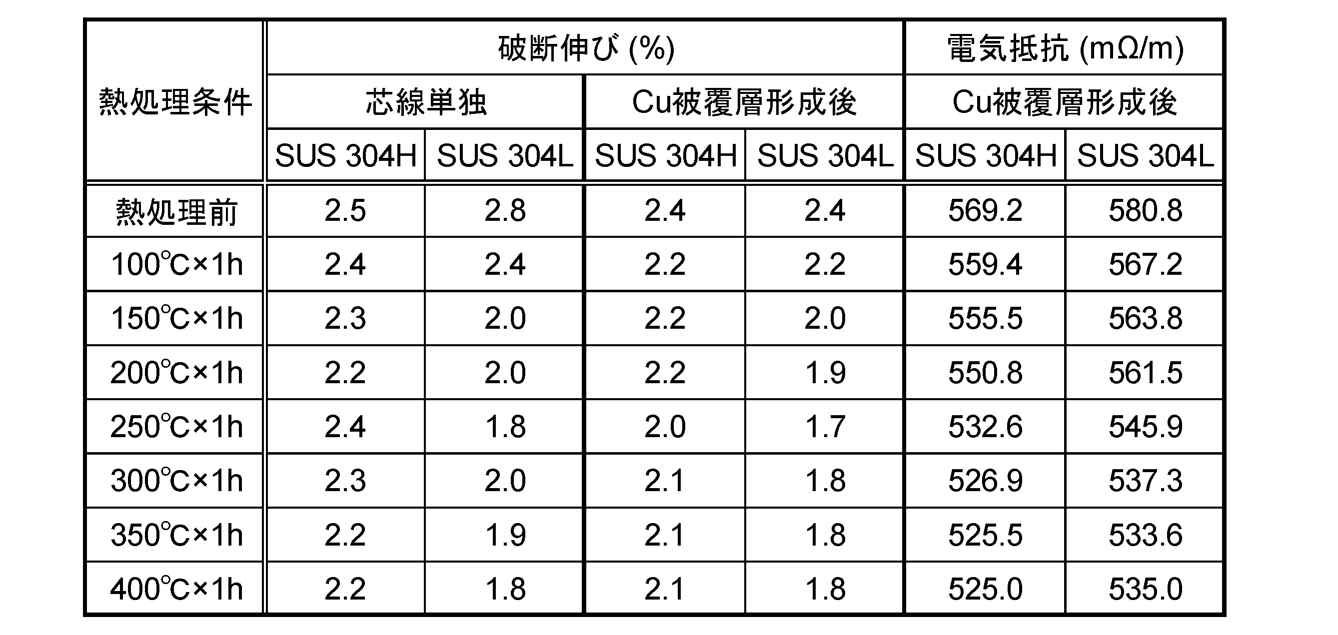
- SUS 304H exhibits a greater elongation at break after heat treatment than SUS 304L, and it was seen in Fig. 4 that SUS 304H provides higher crimp strength in a wider range of tensile strength. presumed to be related to the phenomenon It is also confirmed from Table 2 that the electric resistance value of the electric wire conductor obtained is suppressed to 660 m ⁇ /m or less under all heat treatment conditions when either material of SUS 304H or SUS 304L is used.
- the configuration of the flat electric wire described above can also be applied to the case of using any electric wire conductor other than the electric wire conductor according to the embodiment of the present disclosure.
- any electric wire conductor other than the electric wire conductor according to the embodiment of the present disclosure.
- the diameter of the wire conductor can be reduced.
- the effect of improving the strength can be obtained. That is, in an insulated wire including a plurality of wire conductors, the insulated wire can be configured as follows, with the object of ensuring the wire strength when the diameter of the wire conductor is reduced.
- a plurality of single wire conductors having a conductor cross-sectional area of less than 0.32 mm 2 are arranged in parallel, The outer circumference of each of the electric wire conductors is covered with an insulating coating to form a covering portion, The insulated wire, wherein the covering portions are connected by a connecting portion that is integrated with the insulating covering of the covering portion.
- the distance between at least one set of two adjacent wire conductors is 0.2 mm or more and 1.2 mm or less. In particular, it is preferable that the distance is 1.0 mm or less.
- the form described above can be preferably applied as a configuration related to the flat electric wire.
Landscapes
- Insulated Conductors (AREA)
- Non-Insulated Conductors (AREA)
- Heat Treatment Of Articles (AREA)
- Connections Effected By Soldering, Adhesion, Or Permanent Deformation (AREA)
Abstract
Description
最初に本開示の実施形態を列記して説明する。
本開示にかかる電線導体は、導体断面積が0.13mm2未満であり、電気抵抗が660mΩ/m以下であり、引張強さが950MPa以上であり、破断伸びが1.5%以上であり、単線の状態で使用される。
以下に、本開示の実施形態について、図面を用いて詳細に説明する。本明細書において、「平行」「垂直」等、部材の形状や配置を示す語には、幾何的に厳密な概念のみならず、通信用電線として一般に許容される範囲の誤差も含むものとする。また、本明細書において、各種物性は、大気中、室温(おおむね15~25℃)にて計測される値とする。
本開示の実施形態にかかる通信用電線は、導体断面積が0.13mm2未満であり、電気抵抗が660mΩ/m以下である。そして、引張強さが950MPa以上であり、破断伸びが1.5%以上である。本開示の実施形態にかかる絶縁電線は、上記の電線導体と、電線導体1本の外周を被覆する絶縁被覆と、を有するものである。
次に、上記のように、導体断面積を0.13mm2未満とした場合に、660mΩ/m以下の電気抵抗、950MPa以上の引張強さ、1.5%以上の破断伸びを兼ね備える、単線の電線導体の例として、芯線と被覆層の2層構造を有する電線導体、およびそのような電線導体を備えた絶縁電線について説明する。図1に、そのような電線導体10を含んだ絶縁電線1の断面を表示する。絶縁電線1においては、1本の電線導体10の外周を被覆して、絶縁被覆20が形成されている。

次に、上に挙げたSUS芯線11と銅被覆層12の2層構造を有する電線導体10が有する特性について、詳細に説明する。
上記の2層構造を有する電線導体10を製造する方法としては、例えば、伸線によって所定の径を有するSUSの芯線11を製造したうえで、めっきや蒸着により、銅被覆層12をその芯線11の表面に形成すればよい。あるいは、芯線11となるSUS材の周囲に、銅被覆層12となる環状の銅材を嵌め込み、所定の径まで一体に伸線することでも、電線導体10を製造することができる。
2層構造を有する電線導体10等、本開示の実施形態にかかる電線導体は、どのような形態で使用されてもよく、図1に示したような1本の電線導体10の全周を絶縁被覆20で被覆した単純な絶縁電線1を構成する形態に限られない。上記実施形態にかかる電線導体10を用いて、他の形態の絶縁電線を構成する場合の例として、フラット電線について、簡単に説明する。
まず、SUS芯線と銅被覆層を有する2層構造の電線導体について、電線導体全体としての引張強さおよび各部の硬度と、端子圧着部における圧着強度との関係について検証した。
SUS 304H材よりなる芯線と、純銅よりなる銅被覆層とを有する電線導体を作製した。芯線の外径は、φ0.16mmとし、銅被覆層の厚さは45μmとした。電線導体全体として、外径がφ0.25mm、導体断面積にして0.05mm2となった。得られた電線導体に対して、連続軟化により、熱処理を行った。熱処理条件は、図3の上段に横軸として表示した所定の引張強さが得られるように、それぞれ設定した。加熱温度は、おおむね100℃~400℃の範囲内であった。別途、バッチ式加熱により、100℃~400℃の複数の温度で1時間の熱処理を行った試料も作成した。電線導体の電気抵抗は、いずれの条件の熱処理を経た場合にも、660mΩ/m以下であった。合わせて、参照試料として、導体断面積0.05mm2の銅合金導体(引張強さ:740MPa、破断伸び:2.1%)も準備した。
・電線導体の引張強さ
作製した各電線導体に対して、JIS Z 2241に準拠した引張試験により、破断時の引張強さを評価した。この際、電線導体が全体として破断した時点を、破断時とみなした。測定に際し、評点間距離は250mmとし、引張速度は50mm/minとした。
作製した各電線導体を、軸線方向に垂直に切断し、断面において、芯線および銅被覆層のそれぞれの硬度を測定した。硬度の測定は、マイクロビッカース硬度計を用いて行った。芯線、銅被覆層のそれぞれについて、5か所で測定を行い、平均値を記録した。
作製した電線導体を、長さ104mmに切り出し、圧着端子にて圧着接続して、端子付き導体を得た。圧着端子としては、銅合金製のものを用い、圧着接続に際しては、電線導体の軸線方向に沿って長さ1.6~3.0mmにわたる領域において、電線導体を対向する方向から挟み込んで圧縮した。圧着部としては、導体に対する圧縮度を変化させることで、低圧縮と高圧縮の2とおりの圧着部を形成した。低圧縮の状態は、通常のコネクタ端子と電線導体の間の接続部において採用されるものであり、高圧縮の状態は、通常よりも厳しい条件で電線導体を圧縮している状態に相当する。
図3に、連続軟化による熱処理を経た電線導体について、各種特性(横軸)と、圧着強度(縦軸)との関係を示す。横軸に表示した特性は、上段で電線導体全体の引張強さ、中段でSUS芯線の硬度、下段で銅被覆層の硬度となっている。また、左列に低圧縮の場合、右列に高圧縮の場合を示している。各図では、圧着強度が30Nの水準を、実線で表示している。
ここでは、2層構造の電線導体において、芯線を構成するSUSの伸びが電線導体の特性に与える影響を検証した。
上記の試験[1]では、SUS 304Hよりなる芯線を用いたが、代わりにSUS 304Lよりなる芯線を用いて、同様に電線導体を作製した。連続軟化による熱処理の条件は、SUS 304Hを用いた場合とSUS 304Lを用いた場合で、引張強さがおおむね揃うように、設定した。また、別途、銅被覆層を形成していない状態のSUS 304HおよびSUS 304Lの芯線について、銅被覆層を形成した電線導体と同じ条件で、バッチ式軟化による熱処理を行っておいた。
・引張強さと圧着強度
連続軟化によって熱処理を行った各試料に対して、上記試験[1]と同様の方法で、電線導体の引張強さおよび圧着強度を評価した。
連続軟化およびバッチ式軟化によって熱処理を行った各試料に対して、JIS Z 2241に準拠した引張試験により、破断伸びを評価した。また、合わせて、4端子法によって電気抵抗を測定した。
図4に、芯線にSUS 304Hを用いた場合とSUS 304Lを用いた場合について、電線導体全体の引張強さと圧着強度の関係を示す。また、図中で、各データ点の近傍に、電線導体全体の破断伸びの値を表示する。上図が低圧縮の場合、下図が高圧縮の場合である。図4に示したSUS 304Hについてのデータは、図3に掲載したのと同じものである。
前記電線導体のそれぞれの外周が、絶縁被覆によって被覆されて、被覆部が構成され、
前記被覆部の間が、前記被覆部の前記絶縁被覆と一体となった連結部によって連結されている、絶縁電線。
2 フラット電線
10 電線導体
11 芯線
12 銅被覆層
20 絶縁被覆
25 連結部
30 被覆部
d 電線導体の間の距離
Claims (10)
- 導体断面積が0.13mm2未満であり、
電気抵抗が660mΩ/m以下であり、
引張強さが950MPa以上であり、
破断伸びが1.5%以上であり、
単線の状態で使用される、電線導体。 - 引張強さが1300MPa以下である、請求項1に記載の電線導体。
- ステンレス鋼より構成される単線の芯線と、
銅または銅合金より構成され、前記芯線の外周を被覆する銅被覆層と、を有する、請求項1または請求項2に記載の電線導体。 - 前記電線導体の断面において、
前記芯線の硬度は、650Hv以上、750Hv以下であり、
前記銅被覆層の硬度は、80Hv以上、120Hv以下である、請求項3に記載の電線導体。 - 前記芯線の引張強さは、2400MPa以上、2800MPa以下である、請求項3または請求項4のいずれか1項に記載の電線導体。
- 前記芯線を構成するステンレス鋼は、150℃以上400℃以下の温度で1時間の熱処理を行った際の破断伸びが、1.7%以上である、請求項3から請求項5のいずれか1項に記載の電線導体。
- 前記芯線を構成するステンレス鋼は、SUS 304Hである、請求項3から請求項6のいずれか1項に記載の電線導体。
- 請求項1から請求項7のいずれか1項に記載の電線導体と、
前記電線導体1本の外周を被覆する絶縁被覆と、を有する、絶縁電線。 - 前記電線導体が、複数並列に並べられ、
前記電線導体のそれぞれの外周が、前記絶縁被覆によって被覆されて、被覆部が構成され、
前記被覆部の間が、前記被覆部の前記絶縁被覆と一体となった連結部によって連結されている、請求項8に記載の絶縁電線。 - 前記電線導体のうち、少なくとも1組の隣接する2本の間の距離が、0.2mm以上、1.2mm以下となっている、請求項9に記載の絶縁電線。
Priority Applications (3)
| Application Number | Priority Date | Filing Date | Title |
|---|---|---|---|
| CN202280019057.9A CN116982122A (zh) | 2021-03-31 | 2022-03-28 | 电线导体及绝缘电线 |
| DE112022001985.9T DE112022001985T5 (de) | 2021-03-31 | 2022-03-28 | Drahtleiter und isolierter elektrischer draht |
| US18/283,608 US20240170176A1 (en) | 2021-03-31 | 2022-03-28 | Wire conductor and insulated electric wire |
Applications Claiming Priority (2)
| Application Number | Priority Date | Filing Date | Title |
|---|---|---|---|
| JP2021-061050 | 2021-03-31 | ||
| JP2021061050A JP7615842B2 (ja) | 2021-03-31 | 2021-03-31 | 電線導体および絶縁電線 |
Publications (1)
| Publication Number | Publication Date |
|---|---|
| WO2022210459A1 true WO2022210459A1 (ja) | 2022-10-06 |
Family
ID=83456259
Family Applications (1)
| Application Number | Title | Priority Date | Filing Date |
|---|---|---|---|
| PCT/JP2022/014777 Ceased WO2022210459A1 (ja) | 2021-03-31 | 2022-03-28 | 電線導体および絶縁電線 |
Country Status (5)
| Country | Link |
|---|---|
| US (1) | US20240170176A1 (ja) |
| JP (2) | JP7615842B2 (ja) |
| CN (1) | CN116982122A (ja) |
| DE (1) | DE112022001985T5 (ja) |
| WO (1) | WO2022210459A1 (ja) |
Families Citing this family (1)
| Publication number | Priority date | Publication date | Assignee | Title |
|---|---|---|---|---|
| JP7605385B1 (ja) | 2023-09-20 | 2024-12-24 | 住友電気工業株式会社 | 銅被覆鋼線および絶縁電線 |
Citations (1)
| Publication number | Priority date | Publication date | Assignee | Title |
|---|---|---|---|---|
| WO2020261564A1 (ja) * | 2019-06-28 | 2020-12-30 | 住友電気工業株式会社 | 銅被覆鋼線、ばね、撚線、絶縁電線およびケーブル |
Family Cites Families (9)
| Publication number | Priority date | Publication date | Assignee | Title |
|---|---|---|---|---|
| US4430115A (en) * | 1980-05-27 | 1984-02-07 | Marko Materials, Inc. | Boron stainless steel powder and rapid solidification method |
| US5606151A (en) * | 1993-03-17 | 1997-02-25 | Belden Wire & Cable Company | Twisted parallel cable |
| KR100617465B1 (ko) * | 2003-03-20 | 2006-09-01 | 수미도모 메탈 인더스트리즈, 리미티드 | 고압 수소 가스용 스테인레스강, 그 강으로 이루어지는 용기 및 기기 |
| JP4539559B2 (ja) * | 2003-06-10 | 2010-09-08 | 住友金属工業株式会社 | 水素ガス用オーステナイトステンレス鋼とその製造方法 |
| EP1690957A1 (en) * | 2005-02-14 | 2006-08-16 | Rodacciai S.p.A. | Austenitic stainless steel |
| DE112016006665T5 (de) | 2016-03-31 | 2018-12-20 | Autonetworks Technologies, Ltd. | Kommunikationskabel |
| JP2018037324A (ja) | 2016-09-01 | 2018-03-08 | 矢崎総業株式会社 | 銅クラッドステンレス材料、及びそれを用いた電線 |
| US11693208B2 (en) * | 2019-02-01 | 2023-07-04 | Tdk Taiwan Corp. | Optical sensing system |
| JP7302278B2 (ja) * | 2019-05-20 | 2023-07-04 | 株式会社プロテリアル | コイル及びその製造方法 |
-
2021
- 2021-03-31 JP JP2021061050A patent/JP7615842B2/ja active Active
-
2022
- 2022-03-28 DE DE112022001985.9T patent/DE112022001985T5/de active Pending
- 2022-03-28 WO PCT/JP2022/014777 patent/WO2022210459A1/ja not_active Ceased
- 2022-03-28 US US18/283,608 patent/US20240170176A1/en active Pending
- 2022-03-28 CN CN202280019057.9A patent/CN116982122A/zh active Pending
-
2024
- 2024-12-27 JP JP2024231879A patent/JP2025032009A/ja active Pending
Patent Citations (1)
| Publication number | Priority date | Publication date | Assignee | Title |
|---|---|---|---|---|
| WO2020261564A1 (ja) * | 2019-06-28 | 2020-12-30 | 住友電気工業株式会社 | 銅被覆鋼線、ばね、撚線、絶縁電線およびケーブル |
Also Published As
| Publication number | Publication date |
|---|---|
| JP2022157046A (ja) | 2022-10-14 |
| JP2025032009A (ja) | 2025-03-07 |
| DE112022001985T5 (de) | 2024-01-11 |
| CN116982122A (zh) | 2023-10-31 |
| US20240170176A1 (en) | 2024-05-23 |
| JP7615842B2 (ja) | 2025-01-17 |
Similar Documents
| Publication | Publication Date | Title |
|---|---|---|
| CN112599297B (zh) | 通信用电线 | |
| KR102005669B1 (ko) | 금속/카본 나노튜브 복합 와이어 | |
| US9230716B2 (en) | Coaxial cable | |
| CN1988055B (zh) | 铜合金线,绞合线、同轴电缆、其制造方法及多芯电缆 | |
| JP4143087B2 (ja) | 極細絶縁線と同軸ケーブル及びその製造方法並びにこれを用いた多芯ケーブル | |
| CN103503082A (zh) | 多芯线缆 | |
| JP7265324B2 (ja) | 絶縁電線、ケーブル | |
| JP2025032009A (ja) | 電線導体および絶縁電線 | |
| WO2018092350A1 (ja) | ワイヤーハーネス用撚り線およびワイヤーハーネス | |
| US20110147079A1 (en) | Tension-Resistant Electrical Conductor | |
| JP2025069293A (ja) | 電線導体および絶縁電線 | |
| JP2017199457A (ja) | 高屈曲絶縁電線及びワイヤーハーネス | |
| WO2006008981A1 (ja) | 自動車用電線 | |
| JP2018056101A (ja) | 電線、及び端子付き電線 | |
| EP3113190B1 (en) | Stranded conductor and insulated wire | |
| CN110660525A (zh) | 高频电缆 | |
| JP2008159403A (ja) | 電線導体および絶縁電線 | |
| CN115206591A (zh) | 电线和线束 | |
| CN107430910B (zh) | 绝缘电线 | |
| JP2020191248A (ja) | 端子付き電線、導電性素線、電線、端子付き通信ケーブル及びワイヤハーネス | |
| JP2022151330A (ja) | 通信用電線、端子付き電線及びワイヤハーネス | |
| JP2021144805A (ja) | 接続構造体 | |
| JP7393743B2 (ja) | 電線、及び端子付き電線 | |
| JP7488151B2 (ja) | 圧着端子付き電線 | |
| JP2026053296A (ja) | 圧縮撚線導体、それを用いたケーブル、接続構造 |
Legal Events
| Date | Code | Title | Description |
|---|---|---|---|
| 121 | Ep: the epo has been informed by wipo that ep was designated in this application |
Ref document number: 22780670 Country of ref document: EP Kind code of ref document: A1 |
|
| DPE2 | Request for preliminary examination filed before expiration of 19th month from priority date (pct application filed from 20040101) | ||
| WWE | Wipo information: entry into national phase |
Ref document number: 202280019057.9 Country of ref document: CN |
|
| WWE | Wipo information: entry into national phase |
Ref document number: 18283608 Country of ref document: US |
|
| WWE | Wipo information: entry into national phase |
Ref document number: 112022001985 Country of ref document: DE |
|
| 122 | Ep: pct application non-entry in european phase |
Ref document number: 22780670 Country of ref document: EP Kind code of ref document: A1 |