WO2022210288A1 - プラズマ生成装置、負イオン源装置、及びプラズマ生成装置のメンテナンス方法 - Google Patents
プラズマ生成装置、負イオン源装置、及びプラズマ生成装置のメンテナンス方法 Download PDFInfo
- Publication number
- WO2022210288A1 WO2022210288A1 PCT/JP2022/014099 JP2022014099W WO2022210288A1 WO 2022210288 A1 WO2022210288 A1 WO 2022210288A1 JP 2022014099 W JP2022014099 W JP 2022014099W WO 2022210288 A1 WO2022210288 A1 WO 2022210288A1
- Authority
- WO
- WIPO (PCT)
- Prior art keywords
- chamber
- magnets
- plasma
- magnet
- holding members
- Prior art date
- Legal status (The legal status is an assumption and is not a legal conclusion. Google has not performed a legal analysis and makes no representation as to the accuracy of the status listed.)
- Ceased
Links
Images





Classifications
-
- H—ELECTRICITY
- H01—ELECTRIC ELEMENTS
- H01J—ELECTRIC DISCHARGE TUBES OR DISCHARGE LAMPS
- H01J27/00—Ion beam tubes
- H01J27/02—Ion sources; Ion guns
- H01J27/08—Ion sources; Ion guns using arc discharge
- H01J27/14—Other arc discharge ion sources using an applied magnetic field
-
- H—ELECTRICITY
- H01—ELECTRIC ELEMENTS
- H01J—ELECTRIC DISCHARGE TUBES OR DISCHARGE LAMPS
- H01J37/00—Discharge tubes with provision for introducing objects or material to be exposed to the discharge, e.g. for the purpose of examination or processing thereof
- H01J37/02—Details
- H01J37/04—Arrangements of electrodes and associated parts for generating or controlling the discharge, e.g. electron-optical arrangement or ion-optical arrangement
- H01J37/08—Ion sources; Ion guns
-
- H—ELECTRICITY
- H05—ELECTRIC TECHNIQUES NOT OTHERWISE PROVIDED FOR
- H05H—PLASMA TECHNIQUE; PRODUCTION OF ACCELERATED ELECTRICALLY-CHARGED PARTICLES OR OF NEUTRONS; PRODUCTION OR ACCELERATION OF NEUTRAL MOLECULAR OR ATOMIC BEAMS
- H05H1/00—Generating plasma; Handling plasma
- H05H1/24—Generating plasma
- H05H1/26—Plasma torches
- H05H1/32—Plasma torches using an arc
Definitions
- This plasma generator includes a magnet holder that holds a plurality of magnets that surround the chamber. Also, the magnet holder has a plurality of holding members that hold a plurality of magnets. Thus, the holding member can collectively hold a plurality of magnets. Therefore, when exchanging magnets, a plurality of magnets can be exchanged collectively by the holding member. That is, compared to the case of replacing magnets one by one, the number of times of replacement work, that is, the number of times of work in which problems may occur can be reduced. Therefore, it is possible to reduce problems that occur when exchanging magnets.
- the plasma generator may be provided with an alignment mechanism that aligns the magnet holder with respect to the chamber. In this case, it is possible to improve the positioning accuracy of the magnet holder with respect to the chamber when replacing the magnet.
- At least one holding member has a mating surface for alignment with another holding member, and at least three holes through which screws are passed may be formed in the mating surface.
- two holes can be used for screwing the retaining members together, while the remaining holes can be used for inserting screws to maintain the distance between the other retaining members.
- a negative ion source device is a negative ion source device that includes a plasma generation device that generates plasma and a negative ion extractor that extracts negative ions generated by the plasma, wherein the plasma generation device is internally A plasma generating chamber, a plurality of magnets surrounding the chamber, and a magnet holding section to which the plurality of magnets are attached, the magnet holding section having a plurality of holding members holding the plurality of magnets.
- a plurality of holding members that are detachable around a chamber that internally generates plasma and can hold a plurality of magnets are used to determine the mounting positions of the plurality of magnets with respect to the chamber. to adjust.
- a plurality of magnets may be collectively exchanged using a holding member.
- a plurality of magnets can be exchanged collectively by the holding member. That is, compared to the case of replacing magnets one by one, the number of times of replacement work, that is, the number of times of work in which problems may occur can be reduced. Therefore, it is possible to reduce problems that occur when exchanging magnets.
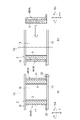
- FIG. 1 is a cross-sectional view showing configurations of a negative ion source device and a plasma generation device according to an embodiment of the present disclosure
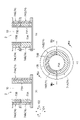
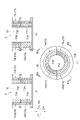
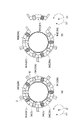
- FIG. FIG. 4 is a schematic diagram showing the structure of the magnet holder when viewed from the vacuum box side in the axial direction
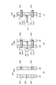
- FIG. 4 is a schematic cross-sectional view of the magnet holder when viewed from a direction perpendicular to the axial direction
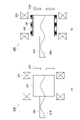
- FIG. 4 is an enlarged cross-sectional view showing the detailed configuration of the flange portion of the holding member
- 4 is an enlarged cross-sectional view showing an alignment mechanism
- FIG. It is the schematic which shows the magnet holding
- the negative ion source device 100 includes a plasma generator 1 and a negative ion extractor 110 .
- the chamber 2 has a cylindrical body portion 10 and a lid portion 11 provided on one end side of the body portion 10 .
- the chamber 2 has a cylindrical shape with the centerline CL as a reference.
- a direction along the center line CL that is, a direction in which the center line CL extends is defined as an axial direction D1.
- a direction around the center line CL is called a circumferential direction D2.
- the side away from the center line CL may be referred to as the "outer peripheral side”
- the side closer to the center line CL may be referred to as the "inner peripheral side”.
- the body portion 10 forms a side wall of the chamber 2 .
- the magnet 3B has an S pole at the inner peripheral end 3Ba and an N pole at the outer peripheral end 3Bb.
- the magnets 3A and 3B are arranged alternately in the circumferential direction D2.
- each magnet 3A, 3B may be constructed by laminating a plurality of permanent magnets in the axial direction D1.
- a magnetic field that can confine the plasma generated in the chamber 2 in the chamber 2 can be generated.
- magnets 3A and 3B can increase the plasma density in chamber 2 .
- the plasma generator 6 has a main body 6a and a pair of filaments 6b extending outward (the other end of the chamber 2, the plasma electrode 116 side) from the end face of the main body 6a.
- the body portion 6 a is attached to the inner wall surface of the lid portion 11 .
- a DC power source (not shown) is connected to the main body 6a. The DC power supply applies voltage and current to the filament 6b to heat the filament 6b and generate a potential difference between the filament 6b and the chamber 2 (main body 10).
- the cesium introduction part 7 is provided in the lid part 11 so as to pass through the lid part 11 .
- the tip of the cesium introduction part 7 is located inside the chamber 2 .
- a cesium supply source 14 as a promoting substance supply unit is connected to the cesium introduction unit 7 , and in this embodiment, cesium is supplied to the chamber 2 in the form of gas (vapor).
- the plasma electrode 116 is arranged between the insulating flange 120 provided on the flange portion 13 located on the other end side of the main body portion 10 and the insulating flange 106 on the vacuum box 104 side.
- the plasma electrode 116 is connected to a variable voltage power supply (not shown). By controlling the power supply to control the magnitude of the voltage applied to the plasma electrode 116, the plasma distribution within the chamber 2 is controlled, and the amount of negative ions extracted from the chamber 2 is controlled.
- the plasma electrode 116 has a through-hole 116a through which the negative ions generated within the chamber 2 can be drawn out of the chamber 2 (to the vacuum box 104 side in this embodiment).
- the plasma electrode 116 generates heat, for example, at about 250° C. due to heat input from the plasma.
- a pipe 116 b connected to the gas supply source 122 is provided near the plasma electrode 116 . That is, the pipe 116b is located on the other end side of the chamber 2.
- the gas supply source 122 includes a source gas source (hydrogen gas source) and an inert gas source (argon gas source). That is, the raw material gas and the inert gas of the gas supply source 122 are supplied into the chamber 2 from the other end side of the main body 10 through the pipe 116b.
- the vacuum box 104 is located downstream of the chamber 2 where the negative ion beam is extracted (the other end of the chamber 2). Like the chamber 108, the vacuum box 104 can keep the inside in a vacuum state. Inside the vacuum box 104, an electrode 124 such as an extraction electrode, a Faraday cup (not shown) for measuring the amount of the negative ion beam, a steering coil (not shown) for changing the trajectory of the negative ion beam, etc. are arranged inside the vacuum box 104. .
- the chamber 2 and the vacuum box 104 are evacuated by a vacuum pump.
- the raw material gas hydrogen gas
- the gas supply source 122 the raw material gas
- the promoting substance cesium gas
- the amount of cesium supplied by the cesium supply source 14 may be adjusted according to the amount of negative ion beam to be extracted.
- Cesium has the function of promoting the generation of negative ions because the surface of a substance to which cesium adheres has a lower work function.
- a current is passed through the plasma generation section 6 and a voltage is applied between the plasma generation section 6 and the chamber 2 .
- a voltage is applied between the filament 6b heated by the flow of current and the chamber 2, thermal electrons are emitted from the filament 6b to the chamber 2, and arc discharge occurs.
- the thermionic electrons collide with the hydrogen gas filling the chamber 2 to eject electrons and turn the hydrogen gas into plasma.
- Negative ions are generated by reaction between the slow electrons or electrons on the surface of the plasma electrode 116 and hydrogen molecules, hydrogen atoms, or hydrogen ions in the plasma.
- the negative ions thus generated are drawn out of the chamber 2 through the opening of the plasma electrode 116 and are irradiated to an external device (for example, an accelerator such as a cyclotron) via the vacuum box 104 .
- FIG. 3 is a schematic cross-sectional view of the magnet holder 4 when viewed in a direction perpendicular to the axial direction D1. Note that FIG. 3 shows a state in which the chamber 2 is not cut.
- FIGS. 2(a) and 3(a) show the holding members 4A and 4B in a state of being completely attached to the chamber 2.
- FIG. 2(b) and 3(b) show the state when the holding member 4B is attached to the chamber 2.
- the magnet holder 4 has a plurality (here, two) of holding members 4A and 4B (first holding members).
- the magnet holder 4 is divided into a plurality of (here, two) holding members 4A and 4B.
- the magnet holding portion 4 includes two holding members 4A and 4B juxtaposed in the circumferential direction D2.
- the magnet holding portion 4 is divided into two holding members 4A and 4B in the circumferential direction D2.
- the holding member 4A and the holding member 4B have a shape obtained by splitting the cylindrical magnet holding portion 4 in half. That is, the holding members 4A and 4B have a shape that draws an arc of 180° when viewed from the axial direction D1.
- the holding members 4A and 4B each have a main body portion 21 in a halved state and a flange portion 22 in a halved state.
- a mating flange portion 24 protruding to the outer peripheral side is formed at one end portion of the holding members 4A and 4B in the circumferential direction D2.
- the matching flange portion 24 is configured in a flat plate shape so as to extend in the axial direction D1 (see FIG. 3(a)).
- a mating flange portion 26 protruding to the outer peripheral side is formed at the other end portion in the circumferential direction D2 of the holding members 4A and 4B.
- the holding member 4A has mating surfaces 4Aa and 4Ab for alignment with the holding member 4B.
- the mating surface 4Aa is provided on one side of the holding member 4A in the circumferential direction D2.
- the mating surface 4Ab is provided on the other side of the holding member 4A in the circumferential direction D2.
- the holding member 4B has mating surfaces 4Ba and 4Bb for alignment with the holding member 4A.
- the mating surface 4Ba is provided on one side of the holding member 4B in the circumferential direction D2.
- the mating surface 4Bb is provided on the other side of the holding member 4B in the circumferential direction D2.
- the holding member 4B is brought close to the chamber 2 from the outer peripheral side and fitted between the flange portions 12 and 13 .
- the holding member 4B is fitted from the side opposite to the holding member 4A across the chamber 2 .
- the holding member 4A is attached to the chamber 2 so as to cover the remaining half region of the body portion 10 of the chamber 2 in the circumferential direction D2.
- the magnet holder 4 is attached to the chamber 2.
- the flange portion 24 has the same structure as the mating flange portion 26 .
- three holes 32A, 32B, and 32C through which screws 31 are passed are formed in the mating surface 4Ab.
- the holes 32A and 32B are arranged so as to be separated from each other.
- Hole 32C is located between hole 32A and hole 32B.
- Holes 33A and 33B are formed in the mating surface 4Bb.
- the screw 31C is protruded from the hole 32C to some extent.
- the tip of the screw 31C is kept away from the mating surface 4Bb.
- screws 31A and 31B are inserted into holes 32A and 32B.
- the screws 31A, 31B passing through the holes 32A, 32B are fastened to the holes 33A, 33B of the mating surface 4Bb.
- the mating surface 4Ab approaches the mating surface 4Bb.
- the tip of the screw 31C comes into contact with the mating surface 4Bb.
- the plasma generator 1 is provided with an alignment mechanism 40 that aligns the magnet holder 4 with respect to the chamber 2 .
- the alignment mechanism 40 has a screw structure 41 and a fitting structure 42 .
- the screwing structure 41 aligns the phases of the magnet holding part 4 and the chamber 2 in the circumferential direction D2 by screwing the flange part 22 of the magnet holding part 4 and the flange part 13 of the chamber 2 with screws 44. can do.
- the flange portion 22 is formed with a through hole 46 through which the screw 44 is inserted, and the flange portion 13 is formed with a tap hole 47 through which the screw 44 is fastened. Therefore, as shown in FIG.
- the screwing structure 41 can align the magnet holder 4 with respect to the chamber 2 .
- the flange portion 22 of the magnet holding portion 4 and the flange portion 13 of the chamber 2 are fitted to each other in the projection portion and the groove portion, so that the phase of the magnet holding portion 4 and the chamber 2 in the circumferential direction D2 is adjusted. can be aligned.
- a projecting portion 48 projecting toward the flange portion 13 is formed on the flange portion 22
- a groove portion 49 is formed on the flange portion 13 . Therefore, as shown in FIG. 5B, by fitting the projecting portion 48 into the groove portion 49, the movement of the magnet holding portion 4 and the chamber 2 in the circumferential direction D2 can be restricted.
- the fitting structure 42 can align the magnet holder 4 with the chamber 2 .
- the plasma generator 1 includes a magnet holder 4 that holds a plurality of magnets 3 covering the circumference of the chamber 2 . Also, the magnet holder 4 has a plurality of holding members 4A and 4B that hold the plurality of magnets 3 . In this manner, the holding members 4A and 4B can collectively hold a plurality of magnets 3 . Therefore, when exchanging the magnets, the plurality of magnets 3 can be exchanged collectively by the holding members 4A and 4B. That is, the number of times of replacement work, that is, the number of times of work in which trouble may occur can be reduced compared to the case where the magnets 3 are replaced one by one. Therefore, it is possible to reduce problems that occur when the magnet 3 is replaced.
- the plasma generator 1 may be provided with an alignment mechanism 40 that aligns the magnet holder 4 with respect to the chamber 2 . In this case, the positioning accuracy of the magnet holder 4 with respect to the chamber 2 can be improved when the magnet 3 is replaced.
- One holding member 4A has mating surfaces 4Aa and 4Ab for alignment with the other holding member 4B.
- the mating surfaces 4Aa and 4Ab have at least three holes 32A and 32B through which screws 31A, 31B and 31C are passed. , 32C may be formed.
- the two holes 32A and 32B are used for fastening the holding members 4A and 4B together with the screws 31A and 31B, while the remaining hole 32C is used for inserting the screw 31C to adjust the distance from the other holding member 4B. can be used to maintain In this case, when joining the holding members 4A and 4B together, it is possible to join the holding members 4A and 4B together while ensuring a safe distance while suppressing sudden movement due to the magnetic force of the magnet 3 .
- a negative ion source device 100 is a negative ion source device 100 that includes a plasma generation device 1 that generates plasma and a negative ion extractor 110 that extracts negative ions generated by the plasma.
- the apparatus 1 includes a chamber 2 for generating plasma inside, a plurality of magnets 3 surrounding the chamber 2, and a magnet holder 4 to which the plurality of magnets 3 are attached. It has a plurality of holding members 4A and 4B that hold the magnets 3 .
- this negative ion source device 100 it is possible to obtain the same functions and effects as the plasma generation device 1 described above.
- the plurality of holding members 4A and 4B that are attachable and detachable around the chamber 2 that internally generates plasma and that can hold the plurality of magnets 3 are used to maintain the chamber 2. Adjust the attachment positions of the plurality of magnets 3 with respect to.
- the mounting positions of the plurality of magnets 3 with respect to the chamber 2 are adjusted using a plurality of holding members 4A and 4B capable of holding a plurality of magnets 3.
- the holding members 4A and 4B can reduce the number of operations by collectively adjusting the attachment positions of the plurality of magnets 3 . Therefore, it is possible to reduce problems that occur when the magnet 3 is replaced.
- a plurality of magnets 3 may be collectively exchanged using the holding members 4A and 4B.
- the plurality of magnets 3 when replacing the magnets, the plurality of magnets 3 can be replaced collectively by the holding members 4A and 4B. That is, the number of times of replacement work, that is, the number of times of work in which trouble may occur can be reduced compared to the case where the magnets 3 are replaced one by one. Therefore, it is possible to reduce problems that occur when the magnet 3 is replaced.
- the magnet holding portion is divided into a plurality of holding members, but the manufacturing process of the holding member does not require a step of dividing one member into a plurality of members. do not have.
- the magnet holding portion 64 may include a plurality of holding members 64A and 64B (second holding members) juxtaposed in the axial direction D1. That is, the magnet holding portion 64 may be divided into a plurality of holding members 64A and 64B in the axial direction D1.
- the holding member 64A and the holding member 64B are attached one by one along the axial direction D1 to the body portion 10 of the chamber 2 from which the flange portion 12 has been removed. be able to.
- the flange portion 12 is fixed to the body portion 10 as shown in FIGS. 6(b) and 6(c).
- the space between the body portion 10 and the flange portion 12 may be vacuum-sealed by a shaft seal or the like.
- the manufacturing cost can be reduced because the welding or brazing process is eliminated.
- holding members 4A and 4B divided in half when the holding members 4A and 4B divided in half are attached to the chamber 2, the holding members 4A and 4B are attached to the chamber 2 from the circumferential direction.
- holding members 4A and 4B divided in half may be attached to the main body 10 of the chamber 2 from the axial direction D1.
- one holding member 4A is attached to the main body 10 of the chamber 2, as shown in FIG. 7(a).
- the other holding member 4B is attached to the main body 10 of the chamber 2.
- FIG. 7C the other holding member 4B is attached to the main body 10 of the chamber 2.
- magnets 73A and magnets 73B with different arrangement patterns may be adopted.
- magnet 73A may be a magnet for forming a multi-cusp magnetic field
- magnet 73B may be a magnet for forming a filter magnetic field.
- the magnets 73A and 73B shown in FIG. 8(c) indicate the range in which the magnets are provided so that the number of magnets is not limited.
- the magnet holding portion 74 may be divided in the axial direction D1 and the circumferential direction D2. Specifically, the magnet holding portion 74 has a half holding member 74A (first holding member).
- the magnet holding portion 74 also has holding members 74B, 74C, 74D, and 74E divided at a pitch of 90°.
- the holding members 74B and 74C (first holding member, second holding member) are attached to the lower side in the axial direction D1.
- the holding members 74D and 74E are attached on the upper side in the axial direction D1.
- the upper holding members 74D and 74E hold magnets 73B with different arrangement patterns.
- the half holding member 74A and the lower holding members 74B and 74C hold the magnet 73A.
- the magnet 73A is arranged on the entire circumference in the circumferential direction D2 on the lower side in the axial direction D1.
- the magnet 73A is arranged in half the area in the circumferential direction D2, and the magnet 73B is arranged in the remaining half area.
- the magnet holding portion 74 includes a holding member 74F (second holding member) attached on the lower side in the axial direction D1, and holding members 74G, 74H, 74I, and 74J (first holding members, 74J) attached on the upper side in the axial direction D1. second holding member).
- the lower holding member 74F surrounds the chamber 2 over the entire circumference in the circumferential direction D2.
- the holding member 74F holds the magnet 73A over the entire circumference in the circumferential direction D2.
- the holding members 74G, 74H, 74I, and 74J on the upper side are divided at a pitch of 90° in the circumferential direction D2.
- the holding members 74G, 74H, 74I and 74J alternately hold the magnets 73A, 73B, 73A and 73B, respectively.
- the magnet 73A is arranged on the entire circumference in the circumferential direction D2 on the lower side in the axial direction D1.
- the magnet 73A is arranged in the 2/4 area in the circumferential direction D2, and the magnet 73B is arranged in the remaining 2/4 area.
- the magnet holding portion may be divided into a number larger than two in the circumferential direction D2.
- the magnet holding portion 84 may be divided into five holding members 84A, 84B, 84C, 84D and 84E in the circumferential direction D2.
- each holding member does not necessarily have to be divided at equal angles.
- the magnet holder may be divided into a holding member corresponding to 270° and a holding member corresponding to 90°.
- the 270° retaining member may be attached to chamber 2 first, followed by the 90° retaining member to chamber 2 .
- the 90° holding member since the 90° holding member has a small number of magnets, it can be attached to the chamber 2 while the influence of the magnetic force is reduced.
- a microwave ion source is an ion source that introduces microwaves into a chamber to generate a plasma.
- the microwave ion source includes a Whistler mode non-resonant microwave ion source, an ECR ion source utilizing Electron Cyclotron Resonance, and the like.
- microwaves cannot enter due to plasma shielding, which limits the improvement of plasma density. and high-density plasma can be generated.
- the mirror magnetic field coil 203 is configured as one coil formed in the same range as the multi-cusp magnetic field magnet 206 .
- one coil in the figure may have a plurality of coils.
- the microwave ion source 200 shown in FIG. 12(b) has a pair of mirror magnetic field magnets 207 in place of the pair of mirror magnetic field coils 203 of FIG. 11(b).
- the multi-cusp magnetic field magnets 206 may be held by a plurality of holding members, and the plurality of multi-cusp magnetic field magnets 206 may be exchanged collectively at the time of replacement. In this case, it becomes possible to easily change the combination of the magnets 206 for the multi-cusp magnetic field, and to adjust the generation of multiply charged ions and the generation of high-density plasma of the microwave ion source.
- the magnets 207 for the mirror magnetic field shown in FIG. 12B may be held by a plurality of holding members so that they can be collectively exchanged.
Landscapes
- Engineering & Computer Science (AREA)
- Physics & Mathematics (AREA)
- Plasma & Fusion (AREA)
- Chemical & Material Sciences (AREA)
- Spectroscopy & Molecular Physics (AREA)
- Analytical Chemistry (AREA)
- Combustion & Propulsion (AREA)
- Electron Sources, Ion Sources (AREA)
- Plasma Technology (AREA)
Abstract
プラズマ生成装置は、内部でプラズマを生成するチャンバと、チャンバの周囲を覆う複数の磁石と、複数の磁石を保持する磁石保持部と、を備え、磁石保持部は、複数の磁石を保持する複数の保持部材を有する。
Description
本開示は、プラズマ生成装置、負イオン源装置、及びプラズマ生成装置のメンテナンス方法に関する。
従来、チャンバ内でプラズマを生成するプラズマ生成装置として、特許文献1に記載されたものが知られている。このプラズマ生成装置は、内部でプラズマを生成するチャンバと、チャンバの周囲を覆う複数の磁石と、を備える。複数の磁石がチャンバの周囲を覆うように配置されることで、チャンバ内で生成されたプラズマをチャンバに閉じ込める磁場を発生する。
ここで、従来のプラズマ生成装置では、一つ一つの磁石について、チャンバの外周に取り付ける作業が行われていた。しかしながら、プラズマ生成装置に用いられる磁石は非常に強力である。そのため、磁石の交換時などに、磁石同士の間で生じる吸引力、又は反発によって、磁石の破損、その他不具合が生じる場合がある。
本開示は、このような課題を解決するためになされたものであり、磁石を交換するときに生じる不具合を低減することができるプラズマ生成装置、負イオン源装置、及びプラズマ生成装置のメンテナンス方法を提供することを目的とする。
本開示に係るプラズマ生成装置は、内部でプラズマを生成するチャンバと、チャンバの周囲を覆う複数の磁石と、複数の磁石を保持する磁石保持部と、を備え、磁石保持部は、複数の磁石を保持する複数の保持部材を有する。
このプラズマ生成装置は、チャンバの周囲を覆う複数の磁石を保持する磁石保持部を備える。また、磁石保持部は、複数の磁石を保持する複数の保持部材を有する。このように、保持部材は、複数の磁石をまとめて保持することができる。そのため、磁石交換時には、保持部材でまとめて、複数の磁石を交換することができる。すなわち、磁石を一つずつ交換する場合に比して、交換作業の回数、すなわち不具合が起き得る作業の回数を減らすことができる。そのため、磁石を交換するときに生じる不具合を低減することができる。
複数の保持部材は、チャンバの中心線周りの周方向において、並置された複数の第1保持部材を含んでよい。また、複数の前記保持部材は、チャンバの中心線に沿った軸方向において、並置された複数の第2保持部材を含んでよい。
プラズマ生成装置には、磁石保持部をチャンバに対して位置合わせする位置合わせ機構が設けられてよい。この場合、磁石の交換時に、磁石保持部のチャンバに対する位置決めの精度を向上することができる。
少なくとも一つの保持部材は、他の保持部材との位置合わせを行う合わせ面を有し、合わせ面には、ねじを通す少なくとも三つの孔が形成されてよい。この場合、二つの孔を保持部材同士をねじで締め付けるために用いる一方、残りの孔をねじを挿入して他方の保持部材との間の距離を維持するために用いることができる。この場合、保持部材同士を接合するときに、磁石の磁力による急激な移動を抑制しながら、安全な距離を確保しながら保持部材同士の接合を行うことができる。
本開示に係る負イオン源装置は、プラズマを生成するプラズマ生成装置と、プラズマによって生成した負イオンを引き出す負イオン引出部と、を備える負イオン源装置であって、プラズマ生成装置は、内部でプラズマを生成するチャンバと、チャンバの周囲を覆う複数の磁石と、複数の磁石が取り付けられた磁石保持部と、を備え、磁石保持部は、複数の磁石を保持する複数の保持部材を有する。
この負イオン源装置によれば、上述のプラズマ生成装置と同趣旨の作用・効果を得ることができる。
本開示に係るプラズマ生成装置のメンテナンス方法では、内部でプラズマを生成するチャンバの周囲に着脱可能であり、複数の磁石を保持可能な複数の保持部材を用いて、チャンバに対する複数の磁石の取り付け位置を調整する。
このプラズマ生成装置のメンテナンス方法では、複数の磁石を保持可能な複数の保持部材を用いて、チャンバに対する複数の磁石の取り付け位置を調整する。このように、保持部材は、複数の磁石をまとめて取り付け位置を調整することで、作業回数を低減できる。そのため、磁石を交換するときに生じる不具合を低減することができる。
保持部材を用いて複数の磁石をまとめて交換してよい。この場合、磁石交換時には、保持部材でまとめて、複数の磁石を交換することができる。すなわち、磁石を一つずつ交換する場合に比して、交換作業の回数、すなわち不具合が起き得る作業の回数を減らすことができる。そのため、磁石を交換するときに生じる不具合を低減することができる。
本開示によれば、磁石を交換するときに生じる不具合を低減することができるプラズマ生成装置、及び負イオン源装置を提供できる。
本開示の実施形態について図面を参照して説明するが、以下の本実施形態は、本開示を説明するための例示であり、本開示を以下の内容に限定する趣旨ではない。説明において、同一要素又は同一機能を有する要素には同一符号を用いることとし、重複する説明は省略する。
まず、図1を参照して、本開示の実施形態に係る負イオン源装置100、及びプラズマ生成装置1の構成について説明する。負イオン源装置100は、プラズマ生成装置1と、負イオン引出部110と、を備える。
プラズマ生成装置1は、チャンバ2の内部でプラズマを生成すると共に、プラズマによって負イオンを生成する装置である。プラズマ生成装置1は、チャンバ2と、複数の磁石3と、磁石保持部4と、プラズマ生成部6と、セシウム導入部7と、を有する。
チャンバ2は、円筒状を呈する本体部10と、本体部10の一端側に設けられた蓋部11とを有する。チャンバ2は、中心線CLを基準とした円筒形状を有する。なお、中心線CLに沿った方向、すなわち中心線CLが延びる方向を軸方向D1とする。また、中心線CL周りの方向を周方向D2と称する。また、中心線CLと直交する方向において、当該中心線CLから遠ざかる側を「外周側」と称し、中心線CLへ近づく側を「内周側」と称することがある。本体部10は、チャンバ2の側壁をなしている。本体部10の軸方向D1における両端には、中心線CLに対する外周側へ向けて突出するフランジ部12,13がそれぞれ設けられている。蓋部11は、本体部10の軸方向D1の一端側に位置するフランジ部13に着脱自在に取り付けられており、本体部10の軸方向D1の一端を開放又は閉塞する。チャンバ2は、絶縁フランジ106を介して連結された真空ボックス104と連通している。そして、この真空ボックス104には真空ポンプ(不図示)が接続されている。従って、チャンバ2、真空ボックス104、真空ポンプの流れでチャンバ2、真空ボックス104の内部が真空引きされる。
磁石3は、チャンバ2内で生成されたプラズマをチャンバ2に閉じ込める機能を有する。磁石3は、本体部10の外周面側に複数配置されている。より詳しくは、磁石3は、本体部10の外周面とは離間した状態でチャンバ2の外周側に位置する。一つあたりの磁石3は、チャンバ2のフランジ部12,13間において、軸方向D1に延びるように設けられている。磁石3と本体部10の外周面との間、または本体部10の内部には、図示しない冷却機構が設けられている。磁石3及び本体部10の壁部の少なくとも一方を冷却するために、当該冷却路内には水などの冷媒が循環される。
ここで、図2は、軸方向D1における真空ボックス104側から見たときの磁石保持部4の構造を示す概略図である。なお、図2では、本体部10の断面が示されている。図2(a)に示すように、複数の磁石3が、チャンバ2の本体部10を囲むように、周方向D2に互いに所定ピッチの間隔を空けた状態で配列される(図2(a)参照)。複数の磁石3として、互いに極性の向きが異なる複数の磁石3A,3Bが配置される。例えば、磁石3Aは、内周側の端部3AaがN極であり、外周側の端部3AbがS極である。一方、磁石3Bは、内周側の端部3BaがS極であり、外周側の端部3BbがN極である。磁石3Aと磁石3Bとは、周方向D2において互い違いとなるように配置される。なお、一つ当たりの磁石3A,3Bは、軸方向D1において、複数個の永久磁石を積層することによって構成されてよい。このように、複数の磁石3A,3Bが周方向D2に交互に配置されることで、チャンバ2内で生成されたプラズマをチャンバ2に閉じ込めることができる磁場を発生することができる。これにより、磁石3A,3Bは、チャンバ2内のプラズマの密度を上げることができる。
磁石保持部4は、上述のような配置となるように複数の磁石3を保持する。磁石保持部4は、本体部21と、フランジ部22(図1参照)と、を備える。本体部21は、中心線CLを基準とした円筒形状を有する。本体部21は、本体部10は、チャンバ2の本体部10と外周側の位置で対向するような側壁をなしている。本体部21の内周面には、上述のように配置された複数の磁石3A,3Bが取り付けられる。
図1に示すように、フランジ部22は、本体部10の軸方向D1における一端側(蓋部11側)において、中心線CLに対する外周側へ向けて突出するように設けられる。フランジ部22は、チャンバ2のフランジ部13に接合される。本体部10の軸方向D1における他端側(真空ボックス104側)の端部は、チャンバ2のフランジ部12の位置まで延びている。フランジ部22は、チャンバ2の他端側、プラズマ電極116側にあってもよい。
プラズマ生成部6は、本体部6aと、本体部6aの端面から外方(チャンバ2の他端側、プラズマ電極116側)に延びる一対のフィラメント6bとを有する。本体部6aは、蓋部11の内壁面に取り付けられている。本体部6aには、図示しない直流電源が接続されている。当該直流電源は、フィラメント6bに電圧及び電流を印加し、フィラメント6bを発熱させると共に、フィラメント6bとチャンバ2(本体部10)との間に電位差を生じさせる。
セシウム導入部7は、蓋部11を貫通するように蓋部11に設けられている。セシウム導入部7の先端は、チャンバ2内に位置している。セシウム導入部7には、促進物質供給部としてのセシウム供給源14が接続されており、本実施形態では、セシウムが気体(蒸気)の状態でチャンバ2に供給される。
負イオン引出部110は、プラズマ生成装置1のプラズマによって生成した負イオンをチャンバ2の外部へ引き出すユニットである。負イオン引出部110は、プラズマ電極116と、真空ボックス104と、を備える。
プラズマ電極116は、本体部10の他端側に位置するフランジ部13に設けられた絶縁フランジ120と、真空ボックス104側の絶縁フランジ106との間に配置されている。プラズマ電極116は、電圧が可変の電源(図示せず)に接続されている。当該電源を制御してプラズマ電極116に印加される電圧の大きさを制御することにより、チャンバ2内のプラズマ分布を制御し、チャンバ2から引き出される負イオンの量を制御する。プラズマ電極116は、チャンバ2内で生成された負イオンをチャンバ2外(本実施形態では真空ボックス104側)に引き出すことが可能な貫通孔116aを有している。プラズマ電極116は、プラズマからの入熱により、例えば250℃程度に発熱する。
プラズマ電極116の近傍には、ガス供給源122に接続された配管116bが設けられている。すなわち、配管116bは、チャンバ2の他端側に位置している。ガス供給源122は、原料ガス源(水素ガス源)及び不活性ガス源(アルゴンガス源)を含む。すなわち、ガス供給源122の原料ガスや不活性ガスは、配管116bを通じて本体部10の他端側からチャンバ2内に供給される。
真空ボックス104は、チャンバ2のうち負イオンビームが引き出される下流側(チャンバ2の他端側)に位置している。真空ボックス104は、チャンバ108と同様に、内部を真空状態に保持可能である。真空ボックス104内には、引出電極等の電極124、負イオンビームのビーム量を計測するファラデーカップ(図示せず)、負イオンビームの軌道を変化させるステアリングコイル(図示せず)等が配置されている。
上記の負イオン源装置100において、負イオンを生成する際には、まずチャンバ2及び真空ボックス104内を真空ポンプにより真空引きする。次に、ガス供給源122により原料ガス(水素ガス)をチャンバ2内に供給すると共に、セシウム供給源14により促進物質(セシウムガス)をチャンバ2内に供給する。セシウム供給源14によるセシウムの供給量は、引き出したい負イオンビームのビーム量に応じて調整してもよい。セシウムが付着した物質の表面においては仕事関数が低下するので、セシウムは、負イオンの生成を促進する機能を有する。
次に、プラズマ生成部6に電流を流し、プラズマ生成部6とチャンバ2との間に電圧が印加される。電流が流れることにより加熱されたフィラメント6bとチャンバ2との間に電圧が印加されることにより、フィラメント6bからチャンバ2へ熱電子が放出され、アーク放電が起きる。当該熱電子は、チャンバ2内に充満している水素ガスと衝突して電子を弾き出し、当該水素ガスをプラズマ化させる。
プラズマ中に存在する電子のうち高速電子と低速電子とが、磁石によって弁別される。低速電子又はプラズマ電極116表面の電子と、プラズマ中の水素分子、水素原子、又は水素イオンと、が反応することにより、負イオンが生成される。こうして生成された負イオンは、プラズマ電極116の開口部を通じてチャンバ2の外に引き出され、真空ボックス104を介して外部の機器(例えばサイクロトロンなどの加速器)へ照射される。
次に、図2及び図3を参照して、プラズマ生成装置1の磁石保持部4の構成について更に詳細に説明する。図3は、軸方向D1と直交する方向から見たときの磁石保持部4の概略断面図である。なお、図3では、チャンバ2は切断されていない状態が示されている。図2(a)及び図3(a)は、チャンバ2への取付完了状態の保持部材4A,4Bを示す。図2(b)及び図3(b)は、保持部材4Bをチャンバ2に取り付けるときの状態を示す。
図2(a)及び図3(a)に示すように、磁石保持部4は、複数(ここでは二つ)の保持部材4A,4B(第1保持部材)を有する。磁石保持部4は、複数(ここでは二つ)の保持部材4A,4Bに分割されている。磁石保持部4は、周方向D2において、並置された二つの保持部材4A,4Bを含む。磁石保持部4は、周方向D2において、二つの保持部材4A,4Bに分割されている。保持部材4A及び保持部材4Bは、円筒状の磁石保持部4を半割りした形状を有する。すなわち、保持部材4A,4Bは、軸方向D1から見て180°の円弧を描くような形状を有する。保持部材4A,4Bは、それぞれ半割状態の本体部21、及び半割状態のフランジ部22を有する。
図2(a)に示すように、保持部材4A,4Bの周方向D2における一方側の端部には、外周側へ突出する合わせフランジ部24が形成される。合わせフランジ部24は、軸方向D1に延びるように平板状に構成される(図3(a)参照)。保持部材4A,4Bの周方向D2における他方の端部には、外周側へ突出する合わせフランジ部26が形成される。
保持部材4Aは、保持部材4Bとの位置合わせを行う合わせ面4Aa,4Abを有する。合わせ面4Aaは、保持部材4Aの周方向D2における一方側に設けられる。合わせ面4Abは、保持部材4Aの周方向D2における他方側に設けられる。また、保持部材4Bは、保持部材4Aとの位置合わせを行う合わせ面4Ba,4Bbを有する。合わせ面4Baは、保持部材4Bの周方向D2における一方側に設けられる。合わせ面4Bbは、保持部材4Bの周方向D2における他方側に設けられる。組付状態では、合わせ面4Aaと合わせ面4Baとが互いに面接触した状態で接合されると共に、合わせ面4Abと合わせ面4Bbとが互いに面接触した状態で接合される。
具体的には、保持部材4Aの本体部10の周方向D2における一方側の端面、及び合わせフランジ部24の主面によって合わせ面4Aaが構成される。保持部材4Bの本体部10の周方向D2における一方側の端面、及び合わせフランジ部24の主面によって合わせ面4Baが構成される。保持部材4Aの本体部10の周方向D2における他方側の端面、及び合わせフランジ部26の主面によって合わせ面4Abが構成される。保持部材4Bの本体部10の周方向D2における他方側の端面、及び合わせフランジ部26の主面によって合わせ面4Bbが構成される。
図3(b)に示すように、保持部材4A,4Bの取付を行うとき、チャンバ2の本体部10には、フランジ部12及びフランジ部13が両方とも溶接等によって固定された状態である。従って、保持部材4A,4Bは、一つずつ外周側からチャンバ2に取り付けられる。まず、保持部材4Aを外周側からチャンバ2へ近接させ、フランジ部12とフランジ部13との間に嵌め込む。そして、チャンバ2の本体部10の周方向D2における半分の領域を覆うように、保持部材4Aをチャンバ2に取り付ける。これにより、図2(b)に示す状態となる。次に、保持部材4Bを外周側からチャンバ2へ近接させ、フランジ部12とフランジ部13との間に嵌め込む。保持部材4Bは、保持部材4Aとはチャンバ2を挟んで反対側から嵌め込まれる。そして、チャンバ2の本体部10の周方向D2における残り半分の領域を覆うように、保持部材4Aをチャンバ2に取り付ける。これにより、図2(a)に示すように、チャンバ2に磁石保持部4が取り付けられた状態となる。
ここで、図4を参照して、保持部材4A,4Bの合わせフランジ部26の詳細な構成について説明する。なお、フランジ部24は、合わせフランジ部26と同趣旨の構成を有する。図4(a)に示すように、合わせ面4Abには、ねじ31を通す三つの孔32A,32B,32Cが形成される。孔32Aと孔32Bは、互いに離間するように配置されている。孔32Cは、孔32Aと孔32Bとの間に配置される。また、合わせ面4Bbには、孔33A,33Bが形成される。
合わせ面4Bbの孔33Aは、合わせ面4Abの孔32Aと対向する位置に形成される。これにより、孔32A,33Aにはねじ31Aが挿入可能となる。ここで、孔32Aはねじ31Aを挿通させる通し孔である。孔33Aは、ねじ31Aを締結可能なタップ孔である。合わせ面4Bbの孔33Bは、合わせ面4Abの孔32Bと対向する位置に形成される。これにより、孔32B,33Bにはねじ31Bが挿入可能となる。ここで、孔32Bはねじ31Bを挿通させる通し孔である。孔33Bは、ねじ31Bを締結可能なタップ孔である。
合わせ面4Bbのうち、合わせ面4Abの孔32Cと対向する位置には孔は設けられていない。孔32Cはねじ31Cを締結可能なタップ孔である。孔32Cに締結されたねじ31Cは、孔32Cを貫通して、孔32Cに対する締め付け量を増加させたら、合わせ面4Bbと当接する。
例えば、ねじ31Cを孔32Cからある程度突出させておく。このとき、ねじ31Cの先端は、合わせ面4Bbから離間させておく。この状態で、ねじ31A,31Bを孔32A,32Bに挿入する。孔32A,32Bを通過したねじ31A,31Bは、合わせ面4Bbの孔33A,33Bに締結される。ねじ31A,31Bの孔33A,33Bに対する締め付け量を増加させると、合わせ面4Abが合わせ面4Bbに近付く。合わせ面4Abが、合わせ面4Bbにある程度近付くと、ねじ31Cの先端部が合わせ面4Bbに接触する。これにより、図4(b)に示すように、合わせ面4Abと合わせ面4Bbの距離が維持される。ねじ31Cの孔32Cに対する締め付け量を減らすと、ねじ31Cの先端が、合わせ面4Bbから離間する。次に、ねじ31A,31Bの孔33A,33Bに対する締め付け量を増加させると、合わせ面4Abが合わせ面4Bbに近付く。このように、ねじ31Cを緩める動作と、ねじ31A,31Bを締める動作を交互に繰り返すことで、合わせ面4Abが合わせ面4Bbに徐々に近付いていく。そして、図4(c)に示すように、ねじ31Cが合わせ面4Abから突出しないようにした状態で、ねじ31A,31Bの孔33A,33Bに対する締め付け量を増加させると、合わせ面4Abが合わせ面4Bbに面接触する。これにより、保持部材4Aと保持部材4Bとの位置合わせが完了する。なお、位置合わせ用に、合わせ面4Aaと合わせ面4Baとの間にスペーサ(非磁性体、例えばアルミなど)を挟んでもよい。合わせ面4Abと合わせ面4Bbとの間も同様である。
図5に示すように、プラズマ生成装置1には、磁石保持部4をチャンバ2に対して位置合わせする位置合わせ機構40が設けられる。位置合わせ機構40は、ねじ止め構造41と、嵌合構造42と、を有している。ねじ止め構造41は、磁石保持部4のフランジ部22と、チャンバ2のフランジ部13とをねじ44でねじ止めすることで、磁石保持部4とチャンバ2との周方向D2の位相を位置合わせすることができる。フランジ部22にはねじ44を挿通させる通し孔である孔46が形成され、フランジ部13にはねじ44を締結させるタップ孔である孔47が形成される。そのため、図5(b)に示すように、ねじ44を孔46に挿入して孔47に締結することで、磁石保持部4とチャンバ2との周方向D2への移動を規制することができる。以上より、ねじ止め構造41は、磁石保持部4をチャンバ2に対して位置合わせすることができる。
嵌合構造42は、磁石保持部4のフランジ部22と、チャンバ2のフランジ部13とを突出部と溝部とを嵌合させることで、磁石保持部4とチャンバ2との周方向D2の位相を位置合わせすることができる。フランジ部22にはフランジ部13側へ突出する突出部48が形成され、フランジ部13には溝部49が形成される。そのため、図5(b)に示すように、突出部48を溝部49に嵌合させることで、磁石保持部4とチャンバ2との周方向D2への移動を規制することができる。以上より、嵌合構造42は、磁石保持部4をチャンバ2に対して位置合わせすることができる。
次に、本実施形態に係るプラズマ生成装置1の作用・効果について説明する。
プラズマ生成装置1は、チャンバ2の周囲を覆う複数の磁石3を保持する磁石保持部4を備える。また、磁石保持部4は、複数の磁石3を保持する複数の保持部材4A,4Bを有する。このように、保持部材4A,4Bは、複数の磁石3をまとめて保持することができる。そのため、磁石交換時には、保持部材4A,4Bでまとめて、複数の磁石3を交換することができる。すなわち、磁石3を一つずつ交換する場合に比して、交換作業の回数、すなわち不具合が起き得る作業の回数を減らすことができる。そのため、磁石3を交換するときに生じる不具合を低減することができる。
磁石保持部4は、チャンバ2の中心線CL周りの周方向D2において、並置された複数の保持部材4A,4Bを含んでよい。この場合、前述のように、チャンバ2の両端にフランジ部12,13が形成されたままの状態にて、保持部材4A,4Bを取り付けることができる。このようなチャンバ2は、溶接ないしはロー付けで真空シールされている。このようなシールは、Oリングなどの真空シールより、真空性が良く、耐熱性が高い。このように、チャンバ2における真空性、及び耐熱性を向上することができる。
プラズマ生成装置1には、磁石保持部4をチャンバ2に対して位置合わせする位置合わせ機構40が設けられてよい。この場合、磁石3の交換時に、磁石保持部4のチャンバ2に対する位置決めの精度を向上することができる。
一つの保持部材4Aは、他の保持部材4Bとの位置合わせを行う合わせ面4Aa,4Abを有し、合わせ面4Aa,4Abには、ねじ31A,31B,31Cを通す少なくとも三つの孔32A,32B,32Cが形成されてよい。この場合、二つの孔32A,32Bを保持部材4A,4B同士をねじ31A,31Bで締め付けるために用いる一方、残りの孔32Cをねじ31Cを挿入して他方の保持部材4Bとの間の距離を維持するために用いることができる。この場合、保持部材4A,4B同士を接合するときに、磁石3の磁力による急激な移動を抑制しながら、安全な距離を確保しながら保持部材4A,4B同士の接合を行うことができる。
本実施形態に係る負イオン源装置100は、プラズマを生成するプラズマ生成装置1と、プラズマによって生成した負イオンを引き出す負イオン引出部110と、を備える負イオン源装置100であって、プラズマ生成装置1は、内部でプラズマを生成するチャンバ2と、チャンバ2の周囲を覆う複数の磁石3と、複数の磁石3が取り付けられた磁石保持部4と、を備え、磁石保持部は、複数の磁石3を保持する複数の保持部材4A,4Bを有する。
この負イオン源装置100によれば、上述のプラズマ生成装置1と同趣旨の作用・効果を得ることができる。
本開示に係るプラズマ生成装置1のメンテナンス方法では、内部でプラズマを生成するチャンバ2の周囲に着脱可能であり、複数の磁石3を保持可能な複数の保持部材4A,4Bを用いて、チャンバ2に対する複数の磁石3の取り付け位置を調整する。
このプラズマ生成装置1のメンテナンス方法では、複数の磁石3を保持可能な複数の保持部材4A,4Bを用いて、チャンバ2に対する複数の磁石3の取り付け位置を調整する。このように、保持部材4A,4Bは、複数の磁石3をまとめて取り付け位置を調整することで、作業回数を低減できる。そのため、磁石3を交換するときに生じる不具合を低減することができる。
保持部材4A,4Bを用いて複数の磁石3をまとめて交換してよい。この場合、磁石交換時には、保持部材4A,4Bでまとめて、複数の磁石3を交換することができる。すなわち、磁石3を一つずつ交換する場合に比して、交換作業の回数、すなわち不具合が起き得る作業の回数を減らすことができる。そのため、磁石3を交換するときに生じる不具合を低減することができる。
本開示は、上述の実施形態に限定されるものではない。
上記実施形態において磁石保持部は、複数の保持部材に分割されているが、保持部材を製造する工程において、一つの部材を複数の部材へと分割する工程を経ていることを必要とするものではない。
例えば、図6に示すように、磁石保持部64は、軸方向D1において、並置された複数の保持部材64A,64B(第2保持部材)を含んでよい。すなわち、磁石保持部64は、軸方向D1において、複数の保持部材64A,64Bに分割されてよい。
この場合、図6(a)に示すように、フランジ部12が取り外された状態のチャンバ2の本体部10に対して、保持部材64A及び保持部材64Bを軸方向D1に沿って一つずつ取り付けることができる。次に、チャンバ2の本体部10に対する保持部材64A,64Bの取り付けが完了すると、図6(b)(c)に示すように、フランジ部12を本体部10に固定する。このとき、本体部10とフランジ部12との間は軸シールなどで真空シールがなされてもよい。Oリングなどを用いて軸シールを行う場合、溶接ないしはロー付けの工程が無くなるため、製作コストを下げることができる。
上述の図3に示す実施形態では、半割の保持部材4A,4Bをチャンバ2に取り付ける場合、チャンバ2に対して周方向から保持部材4A,4Bを取り付けていた。これに代えて、図7に示すように、チャンバ2の本体部10に対して半割の保持部材4A,4Bを軸方向D1から取り付けてもよい。まず、図7(a)に示すように、一方の保持部材4Aをチャンバ2の本体部10に対して取り付ける。次に、図7(b)(c)に示すように、他方の保持部材4Bをチャンバ2の本体部10に対して取り付ける。
図8に示すように、磁場分布を変えるために、配列パターンが異なる磁石73Aと磁石73Bとを備える構成を採用してもよい。例えば、磁石73Aをマルチカスプ磁場を形成するための磁石とし、磁石73Bをフィルター磁場を形成するための磁石としてよい。なお、図8(c)に示される磁石73A,73Bは、個数が限定されないように、磁石が設けられる範囲を示している。また、磁石保持部74は、軸方向D1及び周方向D2でそれぞれ分割されてよい。具体的に、磁石保持部74は、半割の保持部材74A(第1保持部材)を有している。また、磁石保持部74は、90°ピッチで分割された保持部材74B、74C、74D,74Eを有している。保持部材74B,74C(第1保持部材、第2保持部材)は、軸方向D1における下段側に取り付けられる。また、保持部材74D,74Eは、軸方向D1における上段側に取付られる。上段側の保持部材74D,74Eは、配列パターンが異なる磁石73Bを保持している。半割の保持部材74A、及び下段側の保持部材74B,74Cは、磁石73Aを保持している。これにより、軸方向D1における下段側では、周方向D2の全周に磁石73Aが配置される。軸方向D1における上段側では、周方向D2の半分の領域に磁石73Aが配置され、残りの半分の領域に磁石73Bが配置される。
また、分割態様は図8に示すものに限定されず、図9に示すような構成を採用してもよい。磁石保持部74は、軸方向D1における下段側に取り付けられる保持部材74F(第2保持部材)と、軸方向D1における上段側に取り付けられる保持部材74G,74H,74I,74J(第1保持部材、第2保持部材)と、を有している。下段側の保持部材74Fは、周方向D2の全周にわたってチャンバ2を取り囲む。保持部材74Fは、周方向D2の全周にわたって磁石73Aを保持している。上段側の保持部材74G,74H,74I,74Jは、周方向D2に90°ピッチで分割されている。保持部材74G,74H,74I,74Jは、それぞれ磁石73A,73B,73A,73Bを交互に保持している。これにより、軸方向D1における下段側では、周方向D2の全周に磁石73Aが配置される。軸方向D1における上段側では、周方向D2の2/4の領域に磁石73Aが配置され、残りの2/4の領域に磁石73Bが配置される。これにより、保持部材74Hの磁石73Bと保持部材74Jの磁石73Bとの間で、一方向への磁場を作ることが可能となる。なお、分割数や分割態様は図8及び図9に示すものに限定されず、適宜変更してよい。
また、磁石保持部を周方向D2において2つよりも大きな数にて分割してもよい。例えば、図10に示すように、磁石保持部84は、周方向D2に5つの保持部材84A,84B,84C,84D,84Eに分割されてよい。また、磁石保持部を周方向D2に分割するときに、各保持部材は、必ずしも等角度で分割されていなくともよい。例えば、磁石保持部は、270°に相当する保持部材と、90°に相当する保持部材とに分割されてもよい。この場合、270°の保持部材を先にチャンバ2に取り付け、次に、90°の保持部材をチャンバ2に取り付けてよい。この場合、90°の保持部材は磁石の数が少ないため、磁力の影響を小さくした状態で、チャンバ2に取り付けることができる。
また、本開示におけるプラズマ生成装置の構造は、マイクロ波イオン源に適用されてもよい。マイクロ波イオン源は、マイクロ波をチャンバに導入しプラズマを生成するイオン源である。マイクロ波イオン源は、ホイッスラーモードの非共鳴マイクロ波イオン源、電子サイクロトロン共鳴(Electron Cyclotron Resonance)を利用するECRイオン源などを含んだものである。マイクロ波でプラズマを生成すると、プラズマ遮蔽によってマイクロ波が入らなくなりプラズマ密度の向上に制限がかかってしまうが、カスプ磁場やミラー磁場などの磁場をチャンバに印加することによりマイクロ波がプラズマ中を伝搬し、高密度なプラズマを生成することが出来る。カスプ磁場とミラー磁場を組み合わせたマイクロ波イオン源もあり、磁場分布形状は特に限定されない。圧力条件を含め、ECR条件を満たすような磁場を形成できれば、電子温度を向上させることが出来、多価イオンを多く形成することが期待され、非共鳴では一価のイオン種の割合の高い高密度プラズマを形成することが期待できる。
具体的に、図11(a)に示すように、マイクロ波イオン源200は、チャンバ201と、導波管202と、一対のミラー磁場用コイル203と、引出電極204と、を備える。導波管からマイクロ波MWをチャンバ201内へ導入する。一対のミラー磁場用コイル203は、チャンバ201の周囲を取り囲むように設けられる。チャンバ201内のプラズマ内によって生成されたイオンは、引出電極204によって引き出される。図11(b)は、図11(a)に示すマイクロ波イオン源200に対して、マルチカスプ磁場用磁石206を追加したものである。図12(a)に示すマイクロ波イオン源200は、ミラー磁場用コイル203が、マルチカスプ磁場用磁石206と同範囲に形成された一つのコイルとして構成されている。または、図中の一つのコイルの中に複数のコイルを有していてもよい。図12(b)に示すマイクロ波イオン源200は、図11(b)の一対のミラー磁場用コイル203に代えて一対のミラー磁場用磁石207を有する。
上述のマイクロ波イオン源において、マルチカスプ磁場用磁石206を複数の保持部材で保持し、交換時には複数のマルチカスプ磁場用磁石206をまとめて交換してもよい。この場合、マルチカスプ磁場用磁石206の組み合わせの変更を容易に行うことが出来るようになり、マイクロ波イオン源の多価イオン生成、高密度プラズマ生成を調整できる。なお、図12(b)のミラー磁場用磁石207を複数の保持部材で保持することでまとめて交換可能な構成としてもよい。
1…プラズマ生成装置、2…チャンバ、3…磁石、4,64,74,84…磁石保持部、4A,4B,64A,64B,74A,74B,74C,74D,74E,84A,84B,84C,84D,84E…保持部材、40…位置合わせ機構、100…負イオン源装置、110…負イオン引出部、200…マイクロ波イオン源(負イオン源装置)、201…チャンバ、206…マルチカスプ磁場用磁石(磁石)、207…ミラー磁場用磁石(磁石)。
Claims (8)
- 内部でプラズマを生成するチャンバと、
前記チャンバの周囲を覆う複数の磁石と、
複数の前記磁石を保持する磁石保持部と、を備え、
前記磁石保持部は、複数の前記磁石を保持する複数の保持部材を有する、プラズマ生成装置。 - 複数の前記保持部材は、前記チャンバの中心線周りの周方向において、並置された複数の第1保持部材を含む、請求項1に記載のプラズマ生成装置。
- 複数の前記保持部材は、前記チャンバの中心線に沿った軸方向において、並置された複数の第2保持部材を含む、請求項1又は2に記載のプラズマ生成装置。
- 前記磁石保持部を前記チャンバに対して位置合わせする位置合わせ機構が設けられる、請求項1~3の何れか一項に記載のプラズマ生成装置。
- 少なくとも一つの前記保持部材は、他の前記保持部材との位置合わせを行う合わせ面を有し、
前記合わせ面には、ねじを通す少なくとも三つの孔が形成される、請求項1~4の何れか一項に記載のプラズマ生成装置。 - プラズマを生成するプラズマ生成装置と、
前記プラズマによって生成した負イオンを引き出す負イオン引出部と、を備える負イオン源装置であって、
前記プラズマ生成装置は、
内部でプラズマを生成するチャンバと、
前記チャンバの周囲を覆う複数の磁石と、
複数の前記磁石が取り付けられた磁石保持部と、を備え、
前記磁石保持部は、複数の前記磁石を保持する複数の保持部材を有する、負イオン源装置。 - 内部でプラズマを生成するチャンバの周囲に着脱可能であり、複数の磁石を保持可能な複数の保持部材を用いて、前記チャンバに対する前記複数の磁石の取り付け位置を調整する、プラズマ生成装置のメンテナンス方法。
- 前記保持部材を用いて前記複数の磁石をまとめて交換する、請求項7のプラズマ生成装置のメンテナンス方法。
Applications Claiming Priority (2)
| Application Number | Priority Date | Filing Date | Title |
|---|---|---|---|
| JP2021-057658 | 2021-03-30 | ||
| JP2021057658A JP2024072899A (ja) | 2021-03-30 | 2021-03-30 | プラズマ生成装置、及び負イオン源装置 |
Publications (1)
| Publication Number | Publication Date |
|---|---|
| WO2022210288A1 true WO2022210288A1 (ja) | 2022-10-06 |
Family
ID=83458855
Family Applications (1)
| Application Number | Title | Priority Date | Filing Date |
|---|---|---|---|
| PCT/JP2022/014099 Ceased WO2022210288A1 (ja) | 2021-03-30 | 2022-03-24 | プラズマ生成装置、負イオン源装置、及びプラズマ生成装置のメンテナンス方法 |
Country Status (2)
| Country | Link |
|---|---|
| JP (1) | JP2024072899A (ja) |
| WO (1) | WO2022210288A1 (ja) |
Citations (3)
| Publication number | Priority date | Publication date | Assignee | Title |
|---|---|---|---|---|
| JPH11339673A (ja) * | 1998-05-29 | 1999-12-10 | Toshiba Corp | 負イオン源 |
| JP2006049020A (ja) * | 2004-08-02 | 2006-02-16 | Japan Atom Energy Res Inst | Ecrイオン源に用いられるプラズマ閉じ込め用のミラー磁場発生装置及び方法 |
| JP2015138640A (ja) * | 2014-01-22 | 2015-07-30 | 住友重機械工業株式会社 | 負イオン源装置 |
-
2021
- 2021-03-30 JP JP2021057658A patent/JP2024072899A/ja active Pending
-
2022
- 2022-03-24 WO PCT/JP2022/014099 patent/WO2022210288A1/ja not_active Ceased
Patent Citations (3)
| Publication number | Priority date | Publication date | Assignee | Title |
|---|---|---|---|---|
| JPH11339673A (ja) * | 1998-05-29 | 1999-12-10 | Toshiba Corp | 負イオン源 |
| JP2006049020A (ja) * | 2004-08-02 | 2006-02-16 | Japan Atom Energy Res Inst | Ecrイオン源に用いられるプラズマ閉じ込め用のミラー磁場発生装置及び方法 |
| JP2015138640A (ja) * | 2014-01-22 | 2015-07-30 | 住友重機械工業株式会社 | 負イオン源装置 |
Also Published As
| Publication number | Publication date |
|---|---|
| JP2024072899A (ja) | 2024-05-29 |
Similar Documents
| Publication | Publication Date | Title |
|---|---|---|
| JP3843376B2 (ja) | イオン注入のためのイオン源装置 | |
| US6236163B1 (en) | Multiple-beam ion-beam assembly | |
| JPH02501965A (ja) | 電子サイクロトロン共鳴プラズマ源 | |
| JP7194053B2 (ja) | イオン生成装置およびイオン注入装置 | |
| GB2162365A (en) | Ion source | |
| US7624566B1 (en) | Magnetic circuit for hall effect plasma accelerator | |
| JP7096779B2 (ja) | イオン源、およびこれを用いた円形加速器ならびに粒子線治療システム | |
| JPH11354508A (ja) | イオンビーム加工装置 | |
| WO2013030954A1 (ja) | スパッタリング薄膜形成装置 | |
| JP2007165250A (ja) | マイクロ波イオン源、線形加速器システム、加速器システム、医療用加速器システム、高エネルギービーム応用装置、中性子発生装置、イオンビームプロセス装置、マイクロ波プラズマ源及びプラズマプロセス装置 | |
| US20040195521A1 (en) | Ion sorces | |
| JP5475506B2 (ja) | スパッタリング薄膜形成装置 | |
| CN114787956A (zh) | 采用等离子体阴极的电子束焊接系统 | |
| JP2024072899A (ja) | プラズマ生成装置、及び負イオン源装置 | |
| JP2005050646A (ja) | 高周波電子銃 | |
| CN113661556B (zh) | 带电粒子线装置 | |
| WO2018096648A1 (ja) | 加速器および粒子線照射装置 | |
| JP7325597B2 (ja) | イオン生成装置およびイオン注入装置 | |
| JP6124709B2 (ja) | マイクロ波イオン源 | |
| EP4694580A1 (en) | Ion source, accelerator, and particle beam therapy system | |
| Keller | High-intensity ion sources for accelerators with emphasis on H− beam formation and transport | |
| TWI823457B (zh) | 濺鍍裝置 | |
| JP7429154B2 (ja) | マイクロ波イオン源とそれを備えた粒子加速システム | |
| JP2004207148A (ja) | 負イオン源および負イオンビーム発生方法 | |
| Morishita et al. | Spatial uniformity of negative ion production in volume negative ion source |
Legal Events
| Date | Code | Title | Description |
|---|---|---|---|
| 121 | Ep: the epo has been informed by wipo that ep was designated in this application |
Ref document number: 22780502 Country of ref document: EP Kind code of ref document: A1 |
|
| NENP | Non-entry into the national phase |
Ref country code: DE |
|
| 122 | Ep: pct application non-entry in european phase |
Ref document number: 22780502 Country of ref document: EP Kind code of ref document: A1 |
|
| NENP | Non-entry into the national phase |
Ref country code: JP |