WO2022210221A1 - 複合部材、製造物および複合部材の製造方法 - Google Patents
複合部材、製造物および複合部材の製造方法 Download PDFInfo
- Publication number
- WO2022210221A1 WO2022210221A1 PCT/JP2022/013749 JP2022013749W WO2022210221A1 WO 2022210221 A1 WO2022210221 A1 WO 2022210221A1 JP 2022013749 W JP2022013749 W JP 2022013749W WO 2022210221 A1 WO2022210221 A1 WO 2022210221A1
- Authority
- WO
- WIPO (PCT)
- Prior art keywords
- alloy
- base material
- composite member
- property
- hardness
- Prior art date
- Legal status (The legal status is an assumption and is not a legal conclusion. Google has not performed a legal analysis and makes no representation as to the accuracy of the status listed.)
- Ceased
Links
Images


Classifications
-
- B—PERFORMING OPERATIONS; TRANSPORTING
- B22—CASTING; POWDER METALLURGY
- B22F—WORKING METALLIC POWDER; MANUFACTURE OF ARTICLES FROM METALLIC POWDER; MAKING METALLIC POWDER; APPARATUS OR DEVICES SPECIALLY ADAPTED FOR METALLIC POWDER
- B22F7/00—Manufacture of composite layers, workpieces, or articles, comprising metallic powder, by sintering the powder, with or without compacting wherein at least one part is obtained by sintering or compression
- B22F7/06—Manufacture of composite layers, workpieces, or articles, comprising metallic powder, by sintering the powder, with or without compacting wherein at least one part is obtained by sintering or compression of composite workpieces or articles from parts, e.g. to form tipped tools
-
- B—PERFORMING OPERATIONS; TRANSPORTING
- B22—CASTING; POWDER METALLURGY
- B22F—WORKING METALLIC POWDER; MANUFACTURE OF ARTICLES FROM METALLIC POWDER; MAKING METALLIC POWDER; APPARATUS OR DEVICES SPECIALLY ADAPTED FOR METALLIC POWDER
- B22F7/00—Manufacture of composite layers, workpieces, or articles, comprising metallic powder, by sintering the powder, with or without compacting wherein at least one part is obtained by sintering or compression
- B22F7/02—Manufacture of composite layers, workpieces, or articles, comprising metallic powder, by sintering the powder, with or without compacting wherein at least one part is obtained by sintering or compression of composite layers
-
- B—PERFORMING OPERATIONS; TRANSPORTING
- B22—CASTING; POWDER METALLURGY
- B22F—WORKING METALLIC POWDER; MANUFACTURE OF ARTICLES FROM METALLIC POWDER; MAKING METALLIC POWDER; APPARATUS OR DEVICES SPECIALLY ADAPTED FOR METALLIC POWDER
- B22F5/00—Manufacture of workpieces or articles from metallic powder characterised by the special shape of the product
- B22F5/007—Manufacture of workpieces or articles from metallic powder characterised by the special shape of the product of moulds
-
- B—PERFORMING OPERATIONS; TRANSPORTING
- B29—WORKING OF PLASTICS; WORKING OF SUBSTANCES IN A PLASTIC STATE IN GENERAL
- B29C—SHAPING OR JOINING OF PLASTICS; SHAPING OF MATERIAL IN A PLASTIC STATE, NOT OTHERWISE PROVIDED FOR; AFTER-TREATMENT OF THE SHAPED PRODUCTS, e.g. REPAIRING
- B29C33/00—Moulds or cores; Details thereof or accessories therefor
- B29C33/38—Moulds or cores; Details thereof or accessories therefor characterised by the material or the manufacturing process
-
- B—PERFORMING OPERATIONS; TRANSPORTING
- B29—WORKING OF PLASTICS; WORKING OF SUBSTANCES IN A PLASTIC STATE IN GENERAL
- B29C—SHAPING OR JOINING OF PLASTICS; SHAPING OF MATERIAL IN A PLASTIC STATE, NOT OTHERWISE PROVIDED FOR; AFTER-TREATMENT OF THE SHAPED PRODUCTS, e.g. REPAIRING
- B29C45/00—Injection moulding, i.e. forcing the required volume of moulding material through a nozzle into a closed mould; Apparatus therefor
- B29C45/17—Component parts, details or accessories; Auxiliary operations
-
- C—CHEMISTRY; METALLURGY
- C22—METALLURGY; FERROUS OR NON-FERROUS ALLOYS; TREATMENT OF ALLOYS OR NON-FERROUS METALS
- C22C—ALLOYS
- C22C27/00—Alloys based on rhenium or a refractory metal not mentioned in groups C22C14/00 or C22C16/00
- C22C27/04—Alloys based on tungsten or molybdenum
-
- C—CHEMISTRY; METALLURGY
- C22—METALLURGY; FERROUS OR NON-FERROUS ALLOYS; TREATMENT OF ALLOYS OR NON-FERROUS METALS
- C22C—ALLOYS
- C22C30/00—Alloys containing less than 50% by weight of each constituent
-
- B—PERFORMING OPERATIONS; TRANSPORTING
- B22—CASTING; POWDER METALLURGY
- B22F—WORKING METALLIC POWDER; MANUFACTURE OF ARTICLES FROM METALLIC POWDER; MAKING METALLIC POWDER; APPARATUS OR DEVICES SPECIALLY ADAPTED FOR METALLIC POWDER
- B22F1/00—Metallic powder; Treatment of metallic powder, e.g. to facilitate working or to improve properties
- B22F1/05—Metallic powder characterised by the size or surface area of the particles
-
- B—PERFORMING OPERATIONS; TRANSPORTING
- B22—CASTING; POWDER METALLURGY
- B22F—WORKING METALLIC POWDER; MANUFACTURE OF ARTICLES FROM METALLIC POWDER; MAKING METALLIC POWDER; APPARATUS OR DEVICES SPECIALLY ADAPTED FOR METALLIC POWDER
- B22F10/00—Additive manufacturing of workpieces or articles from metallic powder
- B22F10/20—Direct sintering or melting
- B22F10/25—Direct deposition of metal particles, e.g. direct metal deposition [DMD] or laser engineered net shaping [LENS]
-
- B—PERFORMING OPERATIONS; TRANSPORTING
- B22—CASTING; POWDER METALLURGY
- B22F—WORKING METALLIC POWDER; MANUFACTURE OF ARTICLES FROM METALLIC POWDER; MAKING METALLIC POWDER; APPARATUS OR DEVICES SPECIALLY ADAPTED FOR METALLIC POWDER
- B22F10/00—Additive manufacturing of workpieces or articles from metallic powder
- B22F10/20—Direct sintering or melting
- B22F10/28—Powder bed fusion, e.g. selective laser melting [SLM] or electron beam melting [EBM]
-
- B—PERFORMING OPERATIONS; TRANSPORTING
- B22—CASTING; POWDER METALLURGY
- B22F—WORKING METALLIC POWDER; MANUFACTURE OF ARTICLES FROM METALLIC POWDER; MAKING METALLIC POWDER; APPARATUS OR DEVICES SPECIALLY ADAPTED FOR METALLIC POWDER
- B22F7/00—Manufacture of composite layers, workpieces, or articles, comprising metallic powder, by sintering the powder, with or without compacting wherein at least one part is obtained by sintering or compression
- B22F7/06—Manufacture of composite layers, workpieces, or articles, comprising metallic powder, by sintering the powder, with or without compacting wherein at least one part is obtained by sintering or compression of composite workpieces or articles from parts, e.g. to form tipped tools
- B22F7/062—Manufacture of composite layers, workpieces, or articles, comprising metallic powder, by sintering the powder, with or without compacting wherein at least one part is obtained by sintering or compression of composite workpieces or articles from parts, e.g. to form tipped tools involving the connection or repairing of preformed parts
- B22F7/064—Manufacture of composite layers, workpieces, or articles, comprising metallic powder, by sintering the powder, with or without compacting wherein at least one part is obtained by sintering or compression of composite workpieces or articles from parts, e.g. to form tipped tools involving the connection or repairing of preformed parts using an intermediate powder layer
-
- B—PERFORMING OPERATIONS; TRANSPORTING
- B22—CASTING; POWDER METALLURGY
- B22F—WORKING METALLIC POWDER; MANUFACTURE OF ARTICLES FROM METALLIC POWDER; MAKING METALLIC POWDER; APPARATUS OR DEVICES SPECIALLY ADAPTED FOR METALLIC POWDER
- B22F7/00—Manufacture of composite layers, workpieces, or articles, comprising metallic powder, by sintering the powder, with or without compacting wherein at least one part is obtained by sintering or compression
- B22F7/06—Manufacture of composite layers, workpieces, or articles, comprising metallic powder, by sintering the powder, with or without compacting wherein at least one part is obtained by sintering or compression of composite workpieces or articles from parts, e.g. to form tipped tools
- B22F7/08—Manufacture of composite layers, workpieces, or articles, comprising metallic powder, by sintering the powder, with or without compacting wherein at least one part is obtained by sintering or compression of composite workpieces or articles from parts, e.g. to form tipped tools with one or more parts not made from powder
-
- B—PERFORMING OPERATIONS; TRANSPORTING
- B33—ADDITIVE MANUFACTURING TECHNOLOGY
- B33Y—ADDITIVE MANUFACTURING, i.e. MANUFACTURING OF THREE-DIMENSIONAL [3D] OBJECTS BY ADDITIVE DEPOSITION, ADDITIVE AGGLOMERATION OR ADDITIVE LAYERING, e.g. BY 3D PRINTING, STEREOLITHOGRAPHY OR SELECTIVE LASER SINTERING
- B33Y10/00—Processes of additive manufacturing
-
- B—PERFORMING OPERATIONS; TRANSPORTING
- B33—ADDITIVE MANUFACTURING TECHNOLOGY
- B33Y—ADDITIVE MANUFACTURING, i.e. MANUFACTURING OF THREE-DIMENSIONAL [3D] OBJECTS BY ADDITIVE DEPOSITION, ADDITIVE AGGLOMERATION OR ADDITIVE LAYERING, e.g. BY 3D PRINTING, STEREOLITHOGRAPHY OR SELECTIVE LASER SINTERING
- B33Y70/00—Materials specially adapted for additive manufacturing
-
- B—PERFORMING OPERATIONS; TRANSPORTING
- B33—ADDITIVE MANUFACTURING TECHNOLOGY
- B33Y—ADDITIVE MANUFACTURING, i.e. MANUFACTURING OF THREE-DIMENSIONAL [3D] OBJECTS BY ADDITIVE DEPOSITION, ADDITIVE AGGLOMERATION OR ADDITIVE LAYERING, e.g. BY 3D PRINTING, STEREOLITHOGRAPHY OR SELECTIVE LASER SINTERING
- B33Y80/00—Products made by additive manufacturing
Definitions
- the present invention relates to composite members, for example, members suitable for tools, molds, material extruders, cylinders or screws of injection molding machines with excellent durability.
- the mold is often shaped to mold the workpiece into the desired shape.
- conventional molds used for casting and hot-cold working are generally composed of a single composition. Dies come into contact with the workpiece and are subject to various loads, impacts, and thermal effects depending on their shape, and they deteriorate and are damaged by reacting with the workpiece.
- the load applied to the mold during molding varies depending on the shape of the mold. For example, there are locations where the load and impact are high, the sliding speed is high, and the temperature is high.
- the material to be processed is molten metal
- there are parts of the molding surface of the mold where deterioration progresses remarkably due to the influence of the flow velocity and temperature.
- the mold may be damaged by the scale attached to the workpiece.
- Patent Document 1 discloses a technique for improving the corrosion resistance and wear resistance of the obtained thermal spray layer by thermal spraying using an alloy powder containing a Mo2(Ni, Cr)B2 type complex boride. It is
- an object of the present invention is to provide a composite member, a product, and a method of manufacturing a composite member that can efficiently improve the properties of the member against uneven loads.
- the present invention is a composite member comprising a base material made of an alloy, and two or more property-enhancing parts containing an alloy different from the base material and arranged continuously and integrally with respect to the base material.
- the property-enhancing portion has a hardness higher than that of the base material by 50 HV or more, or a corrosion resistance higher than that of the base material by 1.2 times or more.
- the property-enhanced portion has Al erosion resistance higher than that of the base material by 20% or more.
- the property-enhancing portion has a thermal conductivity higher than that of the base material by 5 W/(m ⁇ K) or more.
- the property-enhancing portion has a hardness of 200 HV or more.
- the above-mentioned property-enhanced portion includes a Ni--Cr--Mo-based alloy, a Cr--Mo--Ni--Al-based alloy, a WC--Co-based alloy, a WC--Co--Cu-based alloy, Nb and Mo as the first element group, and At least one of Ta, W, Ti, Hf and Zr is included as the two element groups, and the total of the elements of the first element group and the second element group is 100 at. %, the content range of the contained elements is 5 to 35 at. %, and at least one alloy selected from high entropy alloys containing Ni--Cr--Mo. It is preferable that the thickness of the portion containing the alloy is 0.1 mm or more.
- the present invention also provides a product characterized by including at least a part of the above composite member.
- the above products are tools, molds, material extruders, and cylinders or screws of injection molding machines.
- the present invention is characterized by comprising a processing step of processing a base material made of an alloy, and a shaping step of obtaining a shaped body by shaping the base material with a property-enhancing material containing an alloy different from the base material. It is a manufacturing method of a composite member.
- the present invention it is possible to provide a composite member, a product, and a method of manufacturing a composite member that can efficiently improve the properties of the member against uneven loads.
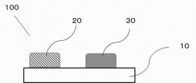
- FIG. 1 is a schematic view of one embodiment of a composite member according to the invention; FIG. It is a figure which shows an example of the use of a composite member.
- FIG. 2 is a schematic diagram showing an example of a manufactured product of a composite member;
- FIG. 2 is a schematic diagram showing an example of a manufactured product of a composite member;
- It is a flowchart which shows an example of the manufacturing method of a composite member.
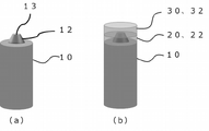
- FIG. 2 is a schematic diagram of a composite member manufactured in Examples. It is a cross-sectional photograph of a composite member manufactured in an example. It is a figure which shows the hardness measurement result in an Example. It is a figure which shows the hardness measurement result in an Example.
- the numerical range of "-" is a range that includes the preceding and following numerical values above and below. Also, in the drawings, the same or similar parts are denoted by the same reference numerals, and the description thereof will not be repeated.
- the composite member is described, then the article of manufacture, and then the method of manufacturing the composite member.
- the composite member referred to in this specification may be a member that is used in contact with the working substance, and the property-enhancing part constitutes at least a part of the part that comes in contact with the working substance. may form part of
- One embodiment of the composite member according to the present invention includes a base material made of an alloy and an alloy having a composition different from that of the base material, and two or more properties are continuously and integrally arranged with respect to the base material.
- Department and It is a composite member having one of the characteristics of having
- a base material serving as a base material and a composite member having two or more property-enhancing portions containing an alloy different from the base material, that is, the property-enhancing portion is at least one surface of the base material. Due to the structure arranged in the part, it is possible to impart arbitrary properties to the member, which are difficult to impart to the member composed only of the base material. Such a configuration effectively enhances the properties of the member under non-uniform loads.
- One embodiment of the composite member as shown in FIG. It has the above characteristic enhancing portions 20 and 30 .
- the base material 10 is not particularly limited, and various metal materials can be used.
- Fe-based alloys, Ni-based alloys, Ti-based alloys, cemented carbides more specifically, alloy tool steels for hot molds used in die casting and the like, cold molds used in press forming Alloy tool steel, high-speed tool steel used for cutting, etc., extrusion mold alloy used for extrusion molding, plastic mold steel used for plastic molding, general steel, stainless steel, etc. can be used. .
- steel types include SKD61, maraging steel, SKD11, SKH51, SCM440, S50C, SUS316L, Alloy718, Stellite 6 (registered trademark of Kennametal Inc.), Ti6Al4V, and the like.
- the property-enhancing parts 20 and 30 are alloys placed in the base material 10 for the purpose of locally strengthening (improving) the properties of the base material 10 .
- the property-enhancing portion has properties different from those of the base material.
- the two or more property-strengthening portions may be made of the same material or an alloy having the same property, or may be made of an alloy having different materials and properties for each of the reinforcing portions.
- the properties referred to in this specification refer to, for example, wear resistance, corrosion resistance, thermal conductivity, erosion resistance, and heat resistance.
- the alloy is not particularly limited as long as it can enhance these characteristics, but it is preferable that the hardness (HV) is 50 HV or more higher or the corrosion resistance is 1.2 times or more higher than that of the base material. Also, the corrosion resistance is preferably twice, more preferably three times that of the base material. Further, the hardness (HV) of the characteristic-enhanced portion is preferably 200 HV, more preferably 300 HV or more, and even more preferably 400 HV or more. Furthermore, it is preferable that the alloy can strengthen two or more of the above properties.
- the thickness of the property-enhancing portion is 0.1 mm or more.
- the property-enhancing portion is preferably configured as a portion of the composite member having a non-uniform thickness rather than a normal coating layer having a uniform thickness. That is, the property-enhancing portion constitutes at least a portion of the portion that comes into contact with the working substance or the like, and can constitute, for example, a portion of the outer shape of the product.
- ⁇ WC-Co alloy> As an alloy constituting the property-enhancing portion, there is, for example, a cemented carbide mainly composed of WC and Co (hereinafter referred to as a WC--Co alloy).
- the hardness of the WC—Co alloy can be adjusted by changing the amount of WC, which is the hard phase, and Co, which is the metal. be.
- the hardness of the TiC--Ni system cermet material can be similarly adjusted by changing the amount of Ni, which is a metal.
- the hard phases are carbides, nitrides, borides, carbonitrides, oxides, and oxynitrides of group 4, 5, and 6 transition metals. Since the hardness can be adjusted, it is preferable as an alloy constituting the characteristic-enhanced portion.
- Ni-based alloy containing Cr and Mo (hereinafter referred to as a Ni--Cr--Mo-based alloy) that can enhance wear resistance and corrosion resistance.
- Ni--Cr--Mo based alloys are Ni-based alloys with the highest Ni content, followed by Cr and Mo in terms of mass ratio.
- an alloy obtained by adding Ta, B, C, and WC as sub-constituent elements to a Ni--Cr--Mo alloy as shown below is preferable.
- Ni-Cr-Mo alloy containing B has the highest Ni content in terms of mass ratio, followed by a Ni-based alloy with a high content of Cr and Mo, and is composed of Cr, Mo and Ni is the main constituent element, and Ta and B are the sub-constituent elements.
- the content of Ni is the largest, and Cr and Mo are preferably contained in the range of Cr: 18% to 22% and Mo: 18% to 39% by mass%.
- the sub-constituent elements Ta and B are preferably contained in the range of Ta: 1.5% to 2.5% and B: 1.0% to 2.5% by mass %.
- the Ni content is specified as the balance with respect to Cr, Mo, Ta and B.
- a strengthening phase When formed as a strengthening phase, it is, for example, a laminate modeled body (sometimes simply referred to as a modeled body) or a cast having a solidified structure, and the solidified structure is a metal phase having a face-centered cubic lattice structure and carbide. It has a dendritic crystal structure.
- Ni--Cr--Mo alloy containing WC as a sub-constituent element has, for example, Cr: 8.5% to 23.0%, Mo: 8.5% to 27.0%, Ta: 0.5% to 2.5%, W: 15.0 to 51.0% and C: 1.0% to 3.5%, the balance consisting of Ni and inevitable impurities, Ni, Cr and Mo
- An alloy having a mass ratio of Ni:Cr:Mo of 2.5-3.5:1:1.0-1.5 can be used.
- ⁇ MoCr-NiAl alloy> an alloy containing Cr, Mo, Ni and Al (MoCr--NiAl-based alloy) can be used as the top four elements having a large content, which can enhance wear resistance and erosion resistance.
- the following chemical composition I when emphasizing erosion resistance, the following chemical composition I can be adopted, and emphasis is placed on the effect of improving galling resistance due to high hardness and lowering the melting point of the alloy composition.
- the following chemical composition II can be adopted.
- Ni is 7.5 to 25 at. %
- Al is 7.5 to 25 at. %
- Cr is 10 to 25 at. %
- the balance is Mo and unavoidable impurities.
- Ni is 20 to 35 at. %
- Al is 20 to 35 at. %
- Cr is 10 to 50 at. %
- the balance is Mo and unavoidable impurities.
- ⁇ WC-Co-Cu alloy> an alloy (WC--Co--Cu-based alloy) obtained by adding Cu to a WC--Co-based alloy, which can enhance wear resistance and thermal conductivity, can be used.
- the ratio a/b of the content b of at least one of (1) satisfies 0.070 ⁇ a/b ⁇ 1.000.
- the thermal conductivity is 40 W / (m K) or more, so that a high thermal conductivity can be realized even for the base material. It is preferable because it is possible to realize a higher value of 5 W/(m ⁇ K) or more with respect to the base material.
- High Entropy alloy which is an alloy with a new technical concept that is distinct from the technical concept of alloys in which a small amount of a plurality of subcomponent elements are added to 1 to 3 main component elements.
- HEA is defined as an alloy composed of 5 or more major metal elements (5 to 35 atomic percent each), and has excellent mechanical properties and corrosion resistance, as well as improved hardness and wear resistance. alloy.
- HEA multi-principal element alloy
- An alloy containing each element of Co, Cr, Fe, Ni, and Ti in a range of 5 atomic % or more and 35 atomic % or less, and containing Mo in a range of more than 0 atomic % and 8 atomic % or less, and the balance being inevitable impurities is possible to obtain a material excellent in softening resistance by applying aging treatment after build-up molding.
- ⁇ Powder high-speed tool steel> high-carbon alloy powder high-speed tool steel containing carbide-forming elements such as Cr, W, Mo, V, and Co, which can enhance wear resistance and heat resistance, can be used.
- carbide-forming elements such as Cr, W, Mo, V, and Co, which can enhance wear resistance and heat resistance
- C is 0.3 to 2.8%
- Cr is 3.0 to 10.0%
- W is 1.5 to 10.5%
- Mo is 2.5%.
- V is 1.0 to 8.0%
- the balance is Fe and unavoidable impurities.
- a high-melting-point metal that can enhance wear resistance and erosion resistance can be used.
- Refractory metals are, for example, W, Ta, Nb, Mo and the like.
- Al corrosion resistance can be enhanced. That is, it is possible to dispose a characteristic-enhanced portion having high Al corrosion resistance even on the base material, and for example, it is possible to achieve Al corrosion resistance higher than that of the base material by 20% or more, which is preferable.
- the hardness (HV) in this specification is, for example, a value measured by a Vickers hardness tester itself, or a value measured by various hardness testers such as Rockwell hardness and Shore hardness. can be used as the value obtained by converting from
- Al erosion resistance is, for example, when evaluating the weight loss when the test material is immersed in molten Al for a certain period of time, compared to the weight loss per unit time of SKD61, refers to a state where the mass change is small. .
- Corrosion resistance is defined by, for example, cutting each test material (alloy member) into a size of 10 mm ⁇ 10 mm ⁇ 2.5 mm, polishing the entire surface of the test piece to waterproof emery paper #1000, and then degreasing with acetone and ethanol. Corrosion test may be performed. Each test piece is immersed in boiling 10% H2SO4 for 24 hours, after which the test piece is removed from the corrosive solution, the mass of each test piece is measured, and the corrosion rate can be obtained from the change in mass. Also, the appearance of the corrosion morphology of the test piece may be observed with a scanning electron microscope (SEM). Moreover, thermal conductivity is a value measured by, for example, a flash method or a temperature gradient method.
- the intermediate layer is preferably made of an austenitic material with high toughness, such as a Ni-based super heat-resistant alloy, an austenitic stainless alloy, or pure Ni.
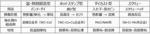
- FIG. For example, it can be applied to applications as shown in FIG.
- a warm forging mold, a screw for an injection molding machine, a hot stamping mold, and a stir bar will be described, but the application is not limited to these.
- the above composite member can be used in various tools such as cutting tools for removal processing, molds for plastic working, jigs and tools such as cutting blades and die cut rolls, molds, material extruders, cylinders or screws for injection molding machines. is suitable for
- FIG. 3 shows a schematic diagram (warm forging punch) showing an example of a product using a composite member.
- YXR33 manufactured by Hitachi Metals, Ltd., YXR is a registered trademark
- WC-20% Co is used for the property-enhancing portion 20 for enhancing properties.
- WC-40% Co can be used for the characteristic enhancing portion 30 .
- matrix high speed steel (as-quenched material) having both hardness and toughness can be used for the base material 10 .
- the parts that are prone to wear due to friction in the high temperature and high pressure environment during forging and the parts that are prone to cracking due to impact are grooved, respectively, to provide WC-20% Co with excellent wear resistance and toughness.
- WC-40% Co which is excellent in sintering, is added by powder build-up molding.
- a laser, plasma, or the like can be used as a heat source for building up the powder.
- the product By cutting the surface of the member after the powder building-up molding and arranging the shape, it is possible to obtain a product having a plurality of characteristic-enhanced portions and made of a plurality of materials. Further, the product may be subjected to surface treatment.
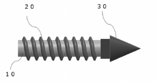
- FIG. 4 shows a schematic diagram of a screw for an injection molding machine as an example of a product using a composite member.
- a screw for an injection molding machine is a product that requires wear resistance and corrosion resistance.
- the base material 10 is stainless steel, and YPT42 (manufactured by Hitachi Metals, Ltd. YPT is a registered trademark) (hardness: 58 HRC) used for small and medium-sized screws and screw tip parts can be used.
- a high entropy alloy (26.7Cr-18.0Fe-26.9Ni-8.9Ti-1.8Mo mass%) can be used for the part 20, and a Ni-Cr-Mo alloy is used for the characteristic strengthening part 30.
- An alloy containing C (46.7Ni-19.0Cr-19.0Mo-1.8Ta-12.0Nb-1.5C mass%) can be used.
- a rod-shaped base material 10 using YPT42 having hardness and corrosion resistance is prepared.
- the fin-shaped portion provided on the outer peripheral portion of the base material 10, that is, the property enhancing portion 20 for enhancing the property is configured.
- high-entropy alloy powder may be added to the periphery of the base material 10 .
- High-entropy alloys have better corrosion resistance than YPT42, and are therefore effective in suppressing corrosion-induced wear.
- one end of the base material 10, that is, a portion to be a screw portion is used as a characteristic-enhanced portion 30, and an alloy containing C (carbon) in a Ni--Cr--Mo alloy is additionally manufactured. Since the screw part requires more wear resistance than the fin-shaped part, it is possible to apply an alloy containing C in a highly corrosion-resistant Ni-Cr-Mo alloy in which hard particles (NbC) are distributed. It is valid.
- FIG. 6 shows a schematic diagram showing an example of the composite member.
- 18% Ni maraging steel is used for the base material A, and YAG300 (Hitachi Metals Co., Ltd. YAG is a registered trademark) used for rocket motor cases and the like can be used.
- the tip of the stirring rod is subject to corrosion due to oxidizing liquids, so MAT21 (MAT21 manufactured by Hitachi Metals, Ltd., a registered trademark), which is a highly corrosion-resistant Ni-based alloy, is added to the B portion, which is the reinforced portion. should be manufactured.
- the side surface of the stirring rod is subject to wear due to impurities deposited in the oxidizing liquid, it is possible to add a CoCrFeNiTiMo high-entropy alloy that has both high strength and high corrosion resistance to the C portion, which is the strengthened portion. good.
- a CoCrFeNiTiMo high-entropy alloy that has both high strength and high corrosion resistance to the C portion, which is the strengthened portion. good.
- the dies used for hot stamping improve the strength of the workpiece by performing quenching by removing heat from the workpiece with a water-cooled mold at the same time as press-molding the heated workpiece.
- a mold is required to have a heat removal function.
- the mold is water-cooled, and it is required that the material forming between the substrate on which the water-cooling holes are arranged and the mold surface has high thermal conductivity. By arranging high thermal conductive materials, the time required for heat removal is shortened and productivity is improved.
- the mold surface is also required to have high hardness.
- an alloy WC-30%Co-5Cuwt% with high thermal conductivity and hardness, it is possible to provide heat removal characteristics and wear resistance characteristics.
- wrinkles are formed in the work material during molding, and local seizure and galling occur here. In such a place, it is effective to improve the wear resistance by additionally manufacturing a higher hardness WC-15% Co alloy or the like.
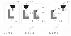
- FIG. 5 An embodiment of a method for manufacturing a composite member will be described with reference to FIG.
- FIG. 5 As an embodiment of the method for manufacturing a composite member, there are a processing step of processing a base material as a base material, and a characteristic reinforcing material containing an alloy different from the base material is formed on the base material. and a molding step of obtaining a molded body.
- the processing step (S101) is a step of processing the base material 10 into a desired shape.
- the processing tool 90 may be used to process the desired shape.
- the modeling step (S103) for example, the property reinforcing material 60 and the property reinforcing material 70 are applied to the base material 10 using the above-described alloy-based alloy powder (property reinforcing material) according to the properties to be imparted.
- a modeled body may be manufactured by adding.
- the addition method is not particularly limited, for example, thermal spraying or addition manufacturing (laminate manufacturing) can be used.
- a finishing process (S105) or a heat treatment process may be additionally performed after the modeling process.
- the finishing step (S105) is a step of processing the shaped body obtained in the shaping step (S103) into a desired shape to obtain a product. can get things.
- the heat treatment step is a step of heat-treating the obtained modeled body or product.
- the additive manufacturing method will be described in detail.
- alloy powder is supplied, and high energy such as a laser beam or an electron beam is applied to the area where the powder is spread to selectively melt and bond the alloy powder, thereby producing a shaped body (composite) of a desired shape. member) can be modeled.
- the additive manufacturing apparatus can be classified into a powder bed fusion method (PBF) and a directed energy deposition method (DED) according to the shape of the modeled body.
- PPF powder bed fusion method
- DED directed energy deposition method
- the composite member of the form can be formed by any method, and the form of the additional manufacturing device is not particularly limited.
- the range of particle size of the alloy powder is preferably 1 to 200 ⁇ m. More preferably, it is 20 to 100 ⁇ m. Further, powder obtained by a gas atomization method that can obtain a spherical shape is preferable.
- the particle size of the powder can be measured using a laser diffraction particle size distribution measuring device. It can be the particle diameter d50 corresponding to the volume %.
- the manufactured composite member will be described with reference to FIG.
- a substrate 10 having a substrate side portion 12 and a substrate tip portion 13 was prepared.
- a composite member was manufactured by additionally manufacturing two kinds of metal powders on the base material 10 at the property-enhancing portion 20 and the property-enhancing portion 30, respectively.
- YAG300 manufactured by Hitachi Metals, Ltd.
- a Ni--Cr--Mo alloy as a characteristic reinforcing material 32 for strengthening the base tip portion 13.
- An alloy powder of a certain MAT 21 is used as a characteristic reinforcing material 22 for strengthening the base tip portion 13 and the base side portion 12.
- An alloy powder of HiPEACE (HiPEACE manufactured by Hitachi Metals, Ltd. is a registered trademark), which is a high entropy alloy, is used as the base material.
- Tables 1 and 2 show the composition of MAT21 used as the property enhancer 32 .
- the particle size was 80.344 ⁇ m with a d50 value.
- Table 3 shows the composition of HiPEACE used as the property reinforcing material 22 .
- the particle size was 88.418 ⁇ m with a d50 value.
- groove processing is performed on the planned additional manufacturing locations.
- the processing conditions were a coated cemented carbide tool with four blades, a cutting speed of 25 m/min, and a one-blade feed rate of 0.05 mm/tooth.
- the additive manufacturing method used the directed energy deposition method.
- the modeling conditions were an output of 2400 W and a scanning speed of 1000 mm/min.
- the hardness of the manufactured composite member was measured. As shown in FIG. 7, the hardness was measured using a sample 500 obtained by cutting, polishing, and embedding the composite member with resin.
- the test piece for hardness measurement is the point A surrounded by a solid line for measuring the hardness transition from the base material 10 to the tip strengthened portion 30 of the sample 500, and the hardness transition from the base material 10 to the side strengthened portion 20. was taken from point B enclosed by a solid line to measure .
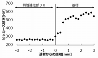
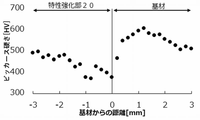
- FIG. 8 shows the results of the Vickers hardness measurement test at point A shown in FIG. 7, and FIG. 9 shows the results of the Vickers hardness measurement test at point B shown in FIG.
- the Vickers hardness was measured at points A and B of the test piece using a micro Vickers.
- the solid lines shown in FIGS. 8 and 9 indicate the surface position of the base material, and the surface of the base material, that is, up to a point advanced by 3 mm in the modeling direction and the opposite direction to the modeling direction with respect to the solid line. Hardness was measured. The measurement interval was 200 ⁇ m. Three lines were measured with a 300 ⁇ m shift, and the average was calculated.
- the measurement conditions were as follows. ⁇ Device name: FM-110ARS-F (manufactured by Futuretech Co., Ltd.) ⁇ Test load: 0.1 kgf ⁇ Holding time: 10 seconds
- the hardness of the property-enhancing portion 30 in which the property-enhancing material 32 is additionally shaped is lower, that is, it can be said that the toughness is improved. Since the property reinforcing material 32 is a highly corrosion-resistant Ni-based alloy, improvement in corrosion resistance of the property reinforcing portion 30 in which the property reinforcing material 32 is additionally shaped can be expected.
- the base material 10 and the portion where the property reinforcing material 22 is additionally shaped differ in hardness. Since the property-enhancing material 22 is a high-strength, high-corrosion-resistant alloy, an improvement in the strength and corrosion resistance of the property-enhancing portion 20 that is additionally shaped can be expected.
- the composite member of this example is applied to, for example, a stirring rod for stirring an oxidizing liquid in which solids are precipitated or floating, the tip of the base material will not be corroded by the oxidizing liquid. can be suppressed, and wear of the base material side surface due to impurities deposited in the oxidizing liquid can be suppressed, so that it is possible to efficiently improve the characteristics of the member against uneven loads.
Landscapes
- Engineering & Computer Science (AREA)
- Mechanical Engineering (AREA)
- Chemical & Material Sciences (AREA)
- Manufacturing & Machinery (AREA)
- Materials Engineering (AREA)
- Composite Materials (AREA)
- Metallurgy (AREA)
- Organic Chemistry (AREA)
- Moulds For Moulding Plastics Or The Like (AREA)
Abstract
Description
本発明に係る複合部材の一実施形態は、合金からなる基材と、前記基材とは異なる組成の合金を含み、前記基材に対して連続一体的に配置された二ヶ所以上の特性強化部と、
を有することを特徴の一つとする複合部材である。
基材10は、特に限定されず、各種金属材料を用いることができる。例えば、Fe基合金、Ni基合金、Ti基合金、超硬合金、より具体的には、ダイカスト等に使用される熱間金型用合金工具鋼、プレス成形に使用される冷間金型用合金工具鋼、切削等に使用される高速度工具鋼、押出成形に使用される押出成形金型用合金、プラスチック成形に用いられるプラスチック金型用鋼、一般鋼、ステンレス鋼などを用いることができる。
特性強化部20および30は、母材である基材10の特性を局所的に強化(向上)することを目的として、基材10に配する合金である。特性強化部は基材と異なる特性を持つ。二ヶ所以上の特性強化部はそれぞれ同じ材料または特性の合金を配置してもよいし、強化部毎に異なる材料・特性の合金を配置してもよい。
特性強化部を構成する合金としては、例えば、WCとCoを主体とする超硬合金(以下、WC-Co系合金と称する)がある。WC-Co系合金は、硬質相であるWCと金属であるCoの量を変えることで硬さを調整することができ、10mass%Co~40mass%Coのとき、硬さはおよそ450HV~1500HVである。TiC-Ni系サーメット材料も同様に金属であるNiの量を変えることで硬さの調整が可能である。その他、硬質サーメットとして、硬質相が4、5、6族遷移金属の炭化物、窒化物、ホウ化物、炭窒化物、酸化物、酸窒化物であり、これらと金属で構成される材料は、硬さの調整ができるため、特性強化部を構成する合金として好ましい。
副構成元素としてBを含有させたNi-Cr-Mo系合金は、質量比でNiの含有量が最も多く、次いでCrおよびMoの含有量が多いNi基合金であって、Cr、MoおよびNiを主構成元素、TaとBを副構成元素としている。例えば、主構成元素のなかで、Niの含有量が最も多く、CrおよびMoは、質量%で、Cr:18%~22%、Mo:18%~39%の範囲で含有されるのが好ましい。また、副構成元素のTaおよびBは、質量%で、Ta:1.5%~2.5%、B:1.0%~2.5%の範囲で含有されるのが好ましい。Niの含有量はCr、Mo、TaおよびBに対して残部として特定される。
副構成元素としてCを含有させたNi-Cr-Mo系合金は、例えば、質量%でCr:18~22%、Mo:18~28%、Ta:1.5~57%、C:1.0~2.5%を含有し、Nb:0~42%、Ti:0~15%、V:0~27%、Zr:0~29%であり、残部がNiおよび不可避不純物からなり、モル比で、(Ta+0.7Nb+Ti+0.6V+Zr)/C=0.5~1.5を満たすことが好ましい。強化相として形成させる場合には、例えば凝固組織を有する積層造形体(単に造形体と称する場合がある)または鋳造物であり、前記凝固組織は、面心立方格子構造である金属相と炭化物を有し、デンドライト状の結晶組織を有している。
副構成元素としてWCを含有させたNi-Cr-Mo系合金は、例えば、質量%で、Cr:8.5%~23.0%、Mo:8.5%~27.0%、Ta:0.5%~2.5%、W:15.0~51.0%およびC:1.0%~3.5%を含有し、残部がNiおよび不可避不純物からなり、Ni、CrおよびMoの質量比Ni:Cr:Moが2.5~3.5:1:1.0~1.5である合金を用いることができる。
また例えば、耐摩耗性と耐溶損性とを強化できる、含有量が大きい上位四元素としてCr、Mo、Ni及びAlを含有した合金(MoCr-NiAl系合金)を用いることができる。合金組成物において、耐溶損性を重視する場合には、以下の化学組成Iを採用でき、硬さが高いことに起因する耐カジリ性の向上や、合金組成物の低融点化という効果を重視する場合には、以下の化学組成IIを採用することができる。
[化学組成I]
Mo+Cr+Ni+Al=100at.%としたとき、Ni+Al=15~50at.%、Mo+Cr=50~85at.%
[化学組成II]
Mo+Cr+Ni+Al=100at.%としたとき、Ni+Al=40~70at.%、Mo+Cr=30~60at.%
また例えば、耐摩耗性と熱伝導率とを強化できる、WC-Co系合金にCuを含有させた合金(WC-Co-Cu系合金)を用いることができる。耐摩耗性と熱伝導率とを強化できる合金として、WC粒子と、Cuと、Co、FeおよびCrのうちの少なくとも1つからなる金属結合相と、を含む合金であり、前記WCの含有量が40質量%以上であり、前記Co、FeおよびCrのうちの少なくとも1つの含有量が25質量%以上60質量%未満であり、前記Cuの含有量aと、前記Co、FeおよびCrのうちの少なくとも1つの含有量bの割合a/bが0.070≦a/b≦1.000を満たすものが良い。上述のWC-Co-Cu系合金であれば、熱伝導率が40W/(m・K)以上であると見込むことができるため、基材に対しても高い熱伝導率を実現でき、具体的には基材に対して5W/(m・K)以上高いことを実現できるので好ましい。
また例えば、1~3種類の主要成分元素に複数種の副成分元素を微量添加した合金の技術思想とは一線を画した新しい技術思想の合金である、ハイエントロピー合金(High Entropy Alloy:HEA)を用いることができる。HEAとは、5種類以上の主要金属元素(それぞれ5~35原子%)から構成された合金と定義されており、機械的特性と耐食性に優れ、更に硬度が改善されて耐摩耗性を備えた合金である。
また、例えば、耐摩耗性、耐熱性を強化できる、高炭素系合金でCr、W、Mo、V、Co等の炭化物形成元素を含有する粉末高速度工具鋼を用いることができる。好ましくは、質量%で、Cが0.3~2.8%であり、Crが3.0~10.0%であり、Wが1.5~10.5%であり、Moが2.0~9.0%であり、Vが1.0~8.0%であり、残部がFe及び不可避不純物である。
また、例えば、耐摩耗性と耐溶損性を強化できる高融点金属を用いることができる。高融点金属とは、例えば、W、Ta、Nb、Mo等である。高融点金属を用いることで耐Al溶損性を高めることができる。すなわち、基材に対しても高い耐Al溶損性を備えた特性強化部を配することができ、例えば、基材に対して20%以上高い耐Al溶損性を実現できるので好ましい。
母材となる基材と、基材と異なる合金を含む特性強化部を2か所以上配した複合部材、すなわち特性強化部が前記基材表面の少なくとも一部に配されている構成により、基材のみで構成された部材では付与するのが困難であった任意の特性を部材に付与することができる。かかる構成によって、一様ではない負荷に対して、部材の特性を効率的に高めることができる。
ここで、本明細書中の硬さ(HV)とは、例えば、ビッカース硬さ試験機そのもので測定した値もしくは、ロックウェル硬さ、ショア硬さなどの各種の硬さ試験機で測定した値から換算して求めた値とするこができる。また、耐Al溶損性とは、例えば、Al溶湯に試験材料を一定時間浸漬した時の質量の減量を評価したとき、SKD61の単位時間当たりの減量と比較し、質量変化が少ない状態を指す。また、耐食性とは、例えば、各供試材(合金部材)を10mm×10mm×2.5mmに切断し、試験片の全面を耐水エメリー紙#1000まで研磨した後、アセトン、エタノールで脱脂して腐食試験に供すればよい。沸騰した10%H2SO4中に各試験片を24時間浸漬し、その後、腐食液から試験片を取り出し、各試験片の質量を測定して、質量変化から腐食速度を求めればよい。また、走査型電子顕微鏡(Scanning Electron Microscope:SEM)によって試験片の外観の腐食形態を観察すればよい。また、熱伝導率とは、例えば、フラッシュ法や温度傾斜法で測定したときの値である。
また例えば、基材と特性強化部との間に中間層を設けることが好ましい。基材に対して異種材である特性強化部を基材に接合させる場合、中間層とよばれる緩衝領域を設けることで、基材と特性強化部との性質差の違いによる、割れや変形、剥離などを生じにくくさせることができる。中間層は、靭性の高いオーステナイト系の材料が好ましく、例えば、Ni基超耐熱合金やオーステナイト系ステンレス合金、あるいは純Niが好ましい。
上記にて説明した複合部材を用いた製造物の実施形態について、図2~図4を用いて説明する。例えば、図2に示すような用途に適用することが出来る。本明細書では、複合部材を用いた製造物の一例として、温間鍛造用金型、射出成型機用スクリュー及びホットスタンプ金型、攪拌棒の場合について説明するが、用途はこれに限らない。例えば、上記複合部材は、除去加工用の切削工具や塑性加工用の金型、切断刃やダイカットロール等の治工具など、各種の工具、金型、材料押出機、射出成形機のシリンダ又はスクリューに好適である。
複合部材の製造方法の実施形態について、図5を用いて説明する。図5に示すように、複合部材の製造方法の実施形態としては、母材となる基材を加工する加工工程と、前記基材に、前記基材と異なる合金を含む特性強化材を造形して造形体を得る造形工程と、を備えていることを特徴の一つとする複合部材の製造方法である。
付加製造法は、合金粉末を供給し、粉末を敷いた領域にレーザビーム、電子ビーム等の高エネルギーを照射して、合金粉末を選択的に溶融結合させることによって、所望形状の造形体(複合部材)を造形することができる。付加製造装置としては、造形体の形状等に応じて、粉末床溶融結合方式(PBF:Powder Bed Fusion)と指向性エネルギー堆積方式(DED:Directed Energy Deposition)に区分することができるが、本実施形態の複合部材はいずれの方式でも造形でき、付加製造装置の形式等については特に制限されるものではない。
図6を用いて、作製した複合部材について説明する。図6(a)に示すように、基材10は、基材側面部12と基材先端部13とを有するものを準備した。そして、図6(b)に示すように、基材10に2種類の金属粉末を特性強化部20および特性強化部30の箇所にそれぞれ付加製造することで、複合部材を作製した。具体的には、基材10とした18%Niマルエージング鋼であるYAG300(日立金属株式会社製)に、基材先端部13を強化するための特性強化材32としてNi-Cr-Mo合金であるMAT21の合金粉末を基材先端部13、基材側面部12を強化するための特性強化材22としてハイエントロピー合金であるHiPEACE(日立金属株式会社製 HiPEACEは登録商標)の合金粉末を基材側面部12にそれぞれ配した複合部材を、付加製造方法を用いて製造した。



・装置名:FM-110ARS-F(株式会社フューチュアテック社製)
・試験荷重:0.1kgf
・保持時間:10秒
図8が示すように、基材10と比較して、特性強化材32が付加造形されている特性強化部30の硬さが低くなり、すなわち靭性が向上したといえる。特性強化材32は高耐食性のNi基合金であるため、特性強化材32が付加造形された特性強化部30の耐食性の向上が期待できる。
12:基材側面部
13:基材先端部
20:特性強化部
22:特性強化材
30:特性強化部
32:特性強化材
60:特性強化材
70:特性強化材
90:加工工具
100:複合部材
500:試料
S101:加工工程
S103:造形工程
S105:仕上げ工程
Claims (9)
- 合金からなる基材と、
前記基材とは異なる組成の合金を含み、前記基材に対して連続一体的に配置された二ヶ所以上の特性強化部と、
を有する複合部材。 - 前記特性強化部は、
前記基材に対して、硬さが50HV以上高い、または耐食性が1.2倍以上高いことを特徴とする請求項1に記載の複合部材。 - 前記特性強化部は、
前記基材に対して、耐Al溶損性が20%以上高いことを特徴とする請求項1または2に記載の複合部材。 - 前記特性強化部は、
前記基材に対して、熱伝導率が5W/(m・K)以上高いことを特徴とする請求項1~3のいずれか一項に記載の複合部材。 - 前記特性強化部は、
硬さが200HV以上であることを特徴とする請求項1~4のいずれか一項に記載の複合部材。 - 前記特性強化部は、
Ni-Cr-Mo系合金、Cr-Mo-Ni-Al系合金、WC-Co系合金、WC-Co-Cu系合金、またはNi-Cr-Moを含むハイエントロピー合金の中から選択された少なくとも1種の合金であり、
前記特性強化部の厚みが0.1mm以上である
ことを特徴とする請求項1~5のいずれか一項に記載の複合部材。 - 請求項1~6のいずれか一項に記載の複合部材を少なくとも一部に含むことを特徴とする製造物。
- 工具、金型、材料押出機、射出成形機のシリンダ又はスクリューであることを特徴とする請求項7に記載の製造物。
- 合金からなる基材を加工する加工工程と、
前記基材の二ヶ所以上に、前記基材と異なる組成の合金を含む特性強化材を造形して造形体を得る造形工程と、を備える複合部材の製造方法。
Priority Applications (2)
| Application Number | Priority Date | Filing Date | Title |
|---|---|---|---|
| US18/284,290 US20240157440A1 (en) | 2021-03-30 | 2022-03-23 | Composite member, product, and method for producing composite member |
| JP2023511094A JPWO2022210221A1 (ja) | 2021-03-30 | 2022-03-23 |
Applications Claiming Priority (2)
| Application Number | Priority Date | Filing Date | Title |
|---|---|---|---|
| JP2021056502 | 2021-03-30 | ||
| JP2021-056502 | 2021-03-30 |
Publications (1)
| Publication Number | Publication Date |
|---|---|
| WO2022210221A1 true WO2022210221A1 (ja) | 2022-10-06 |
Family
ID=83459182
Family Applications (1)
| Application Number | Title | Priority Date | Filing Date |
|---|---|---|---|
| PCT/JP2022/013749 Ceased WO2022210221A1 (ja) | 2021-03-30 | 2022-03-23 | 複合部材、製造物および複合部材の製造方法 |
Country Status (3)
| Country | Link |
|---|---|
| US (1) | US20240157440A1 (ja) |
| JP (1) | JPWO2022210221A1 (ja) |
| WO (1) | WO2022210221A1 (ja) |
Cited By (1)
| Publication number | Priority date | Publication date | Assignee | Title |
|---|---|---|---|---|
| TWI880154B (zh) * | 2023-01-06 | 2025-04-11 | 國立成功大學 | 在鈦-6鋁-4釩基材塗覆碳化鎢並以雷射再熔進行改質的方法 |
Citations (7)
| Publication number | Priority date | Publication date | Assignee | Title |
|---|---|---|---|---|
| JPH05117820A (ja) * | 1991-10-25 | 1993-05-14 | Kubota Corp | 耐摩耗性にすぐれたプラスチツク成形機用部材 |
| WO2017170729A1 (ja) * | 2016-03-29 | 2017-10-05 | 三菱重工コンプレッサ株式会社 | 異種材料を用いた熱溶融積層造形によるインペラ製造方法およびインペラ |
| WO2019031577A1 (ja) * | 2017-08-09 | 2019-02-14 | 日立金属株式会社 | 合金部材、該合金部材の製造方法、および該合金部材を用いた製造物 |
| WO2019069701A1 (ja) * | 2017-10-02 | 2019-04-11 | 日立金属株式会社 | 超硬合金複合材およびその製造方法ならびに超硬工具 |
| WO2020111231A1 (ja) * | 2018-11-29 | 2020-06-04 | 日立金属株式会社 | 付加製造体の製造方法、および、付加製造体の製造装置 |
| WO2020196879A1 (ja) * | 2019-03-27 | 2020-10-01 | 日立金属株式会社 | 合金組成物および合金組成物の製造方法、並びに金型 |
| JP2021042403A (ja) * | 2019-09-06 | 2021-03-18 | 日立金属株式会社 | 複合部材および複合部材の製造方法 |
-
2022
- 2022-03-23 JP JP2023511094A patent/JPWO2022210221A1/ja active Pending
- 2022-03-23 WO PCT/JP2022/013749 patent/WO2022210221A1/ja not_active Ceased
- 2022-03-23 US US18/284,290 patent/US20240157440A1/en active Pending
Patent Citations (7)
| Publication number | Priority date | Publication date | Assignee | Title |
|---|---|---|---|---|
| JPH05117820A (ja) * | 1991-10-25 | 1993-05-14 | Kubota Corp | 耐摩耗性にすぐれたプラスチツク成形機用部材 |
| WO2017170729A1 (ja) * | 2016-03-29 | 2017-10-05 | 三菱重工コンプレッサ株式会社 | 異種材料を用いた熱溶融積層造形によるインペラ製造方法およびインペラ |
| WO2019031577A1 (ja) * | 2017-08-09 | 2019-02-14 | 日立金属株式会社 | 合金部材、該合金部材の製造方法、および該合金部材を用いた製造物 |
| WO2019069701A1 (ja) * | 2017-10-02 | 2019-04-11 | 日立金属株式会社 | 超硬合金複合材およびその製造方法ならびに超硬工具 |
| WO2020111231A1 (ja) * | 2018-11-29 | 2020-06-04 | 日立金属株式会社 | 付加製造体の製造方法、および、付加製造体の製造装置 |
| WO2020196879A1 (ja) * | 2019-03-27 | 2020-10-01 | 日立金属株式会社 | 合金組成物および合金組成物の製造方法、並びに金型 |
| JP2021042403A (ja) * | 2019-09-06 | 2021-03-18 | 日立金属株式会社 | 複合部材および複合部材の製造方法 |
Cited By (1)
| Publication number | Priority date | Publication date | Assignee | Title |
|---|---|---|---|---|
| TWI880154B (zh) * | 2023-01-06 | 2025-04-11 | 國立成功大學 | 在鈦-6鋁-4釩基材塗覆碳化鎢並以雷射再熔進行改質的方法 |
Also Published As
| Publication number | Publication date |
|---|---|
| US20240157440A1 (en) | 2024-05-16 |
| JPWO2022210221A1 (ja) | 2022-10-06 |
Similar Documents
| Publication | Publication Date | Title |
|---|---|---|
| JP7744041B2 (ja) | 構造、機械、工具応用のための長期耐用性高機能鋼鉄 | |
| KR101659704B1 (ko) | 강의 열 전도율을 세팅하는 방법 및 공구강의 용도 | |
| US11247268B2 (en) | Methods of making metal matrix composite and alloy articles | |
| Ghaffari et al. | Grain refinement and strengthening of PH 13-8Mo martensitic stainless steel through TiC/TiB2 inoculation during wire arc additive manufacturing | |
| JPWO2020111231A1 (ja) | 付加製造体の製造方法、および、付加製造体の製造装置 | |
| Michla et al. | Conventional and additively manufactured stainless steels: a review | |
| US20120097297A1 (en) | High hardness, high corrosion resistance and high wear resistance alloy | |
| KR101893172B1 (ko) | 3차원 메탈프린터용 금속분말 및 이를 이용하여 제조되는 전단금형 | |
| Hu et al. | Research and developments of ceramic-reinforced steel matrix composites—A comprehensive review | |
| CN113795603B (zh) | Ni基合金、Ni基合金粉末、Ni基合金构件和具备Ni基合金构件的制造物 | |
| US20210107060A1 (en) | Multi-material tooling and methods of making same | |
| US20240157440A1 (en) | Composite member, product, and method for producing composite member | |
| JP4864426B2 (ja) | 鉄系合金の半溶融・半凝固鋳造用の金型 | |
| JP5567792B2 (ja) | 高硬度耐食耐磨耗合金素材およびそれを用いた耐摩耗性部材並びにその製造方法 | |
| CA2663683C (en) | Component of metal molding system | |
| CN108998816A (zh) | 一种氯化铵助渗的Cr/氮化复合涂层及其制备方法 | |
| JP5547937B2 (ja) | Ni−Cr−Al系合金を用いた錠剤成形用杵および臼 | |
| KR20140101017A (ko) | 강의 열 전도율을 세팅하는 방법 및 공구강의 용도 | |
| JP2025086899A (ja) | 合金部材及び合金部材の製造方法 | |
| CN107338371A (zh) | 一种新型司太立合金及其制备方法 | |
| WO2025216690A1 (en) | A hot forming tool and a method of forming said tool | |
| Sears et al. | Hard, wear resistant metal surfaces for industrial applications through laser powder deposition | |
| Sears | Laser additive manufacturing wc and wc forming alloys and powder blends | |
| Mangukia | Die Materials and Die Manufacturing | |
| JP2006095990A (ja) | 耐摩耗性、耐食性に優れたスクリュ |
Legal Events
| Date | Code | Title | Description |
|---|---|---|---|
| 121 | Ep: the epo has been informed by wipo that ep was designated in this application |
Ref document number: 22780435 Country of ref document: EP Kind code of ref document: A1 |
|
| WWE | Wipo information: entry into national phase |
Ref document number: 2023511094 Country of ref document: JP |
|
| WWE | Wipo information: entry into national phase |
Ref document number: 18284290 Country of ref document: US |
|
| NENP | Non-entry into the national phase |
Ref country code: DE |
|
| 122 | Ep: pct application non-entry in european phase |
Ref document number: 22780435 Country of ref document: EP Kind code of ref document: A1 |