WO2022209924A1 - ロボット遠隔操作制御装置、ロボット遠隔操作制御システム、ロボット遠隔操作制御方法、およびプログラム - Google Patents
ロボット遠隔操作制御装置、ロボット遠隔操作制御システム、ロボット遠隔操作制御方法、およびプログラム Download PDFInfo
- Publication number
- WO2022209924A1 WO2022209924A1 PCT/JP2022/012089 JP2022012089W WO2022209924A1 WO 2022209924 A1 WO2022209924 A1 WO 2022209924A1 JP 2022012089 W JP2022012089 W JP 2022012089W WO 2022209924 A1 WO2022209924 A1 WO 2022209924A1
- Authority
- WO
- WIPO (PCT)
- Prior art keywords
- robot
- operator
- information
- unit
- control device
- Prior art date
Links
- 238000000034 method Methods 0.000 title claims abstract description 105
- 239000012636 effector Substances 0.000 claims abstract description 130
- 230000033001 locomotion Effects 0.000 claims description 276
- 230000009471 action Effects 0.000 claims description 60
- 238000001514 detection method Methods 0.000 claims description 57
- 238000003384 imaging method Methods 0.000 claims description 19
- 230000007246 mechanism Effects 0.000 claims description 14
- 238000006073 displacement reaction Methods 0.000 claims description 7
- 230000002194 synthesizing effect Effects 0.000 claims description 7
- 230000004886 head movement Effects 0.000 claims description 4
- 238000012545 processing Methods 0.000 description 74
- 238000004891 communication Methods 0.000 description 72
- 230000036544 posture Effects 0.000 description 51
- 230000006870 function Effects 0.000 description 45
- 238000010586 diagram Methods 0.000 description 33
- 210000003128 head Anatomy 0.000 description 26
- 238000004364 calculation method Methods 0.000 description 22
- 238000010801 machine learning Methods 0.000 description 20
- 230000005540 biological transmission Effects 0.000 description 16
- 230000001133 acceleration Effects 0.000 description 15
- 230000007613 environmental effect Effects 0.000 description 15
- 230000008569 process Effects 0.000 description 14
- 230000008859 change Effects 0.000 description 13
- 238000012937 correction Methods 0.000 description 11
- 210000004247 hand Anatomy 0.000 description 9
- 210000000707 wrist Anatomy 0.000 description 9
- 238000000605 extraction Methods 0.000 description 8
- 238000012549 training Methods 0.000 description 5
- 238000004458 analytical method Methods 0.000 description 4
- 238000003708 edge detection Methods 0.000 description 4
- 230000006872 improvement Effects 0.000 description 4
- 238000012986 modification Methods 0.000 description 4
- 230000004048 modification Effects 0.000 description 4
- 238000005457 optimization Methods 0.000 description 4
- 230000035945 sensitivity Effects 0.000 description 4
- 230000006399 behavior Effects 0.000 description 3
- 239000012141 concentrate Substances 0.000 description 3
- 238000005516 engineering process Methods 0.000 description 3
- 230000005057 finger movement Effects 0.000 description 3
- 230000004807 localization Effects 0.000 description 3
- 230000009467 reduction Effects 0.000 description 3
- 230000004044 response Effects 0.000 description 3
- 230000004043 responsiveness Effects 0.000 description 3
- 238000011960 computer-aided design Methods 0.000 description 2
- 238000007796 conventional method Methods 0.000 description 2
- 230000036461 convulsion Effects 0.000 description 2
- 210000000245 forearm Anatomy 0.000 description 2
- 238000003875 gradient-accelerated spectroscopy Methods 0.000 description 2
- 238000013507 mapping Methods 0.000 description 2
- 238000005259 measurement Methods 0.000 description 2
- 210000003205 muscle Anatomy 0.000 description 2
- 230000002093 peripheral effect Effects 0.000 description 2
- 230000000452 restraining effect Effects 0.000 description 2
- 230000035807 sensation Effects 0.000 description 2
- 238000000926 separation method Methods 0.000 description 2
- 230000005236 sound signal Effects 0.000 description 2
- 230000001629 suppression Effects 0.000 description 2
- 238000013528 artificial neural network Methods 0.000 description 1
- 230000003542 behavioural effect Effects 0.000 description 1
- 230000004397 blinking Effects 0.000 description 1
- 230000007423 decrease Effects 0.000 description 1
- 238000013461 design Methods 0.000 description 1
- 239000000284 extract Substances 0.000 description 1
- 238000013178 mathematical model Methods 0.000 description 1
- 238000002360 preparation method Methods 0.000 description 1
- 238000007637 random forest analysis Methods 0.000 description 1
- 238000005070 sampling Methods 0.000 description 1
- 239000007787 solid Substances 0.000 description 1
- 230000000007 visual effect Effects 0.000 description 1
Images


Classifications
-
- B—PERFORMING OPERATIONS; TRANSPORTING
- B25—HAND TOOLS; PORTABLE POWER-DRIVEN TOOLS; MANIPULATORS
- B25J—MANIPULATORS; CHAMBERS PROVIDED WITH MANIPULATION DEVICES
- B25J13/00—Controls for manipulators
-
- B—PERFORMING OPERATIONS; TRANSPORTING
- B25—HAND TOOLS; PORTABLE POWER-DRIVEN TOOLS; MANIPULATORS
- B25J—MANIPULATORS; CHAMBERS PROVIDED WITH MANIPULATION DEVICES
- B25J13/00—Controls for manipulators
- B25J13/02—Hand grip control means
-
- B—PERFORMING OPERATIONS; TRANSPORTING
- B25—HAND TOOLS; PORTABLE POWER-DRIVEN TOOLS; MANIPULATORS
- B25J—MANIPULATORS; CHAMBERS PROVIDED WITH MANIPULATION DEVICES
- B25J9/00—Programme-controlled manipulators
- B25J9/16—Programme controls
- B25J9/1679—Programme controls characterised by the tasks executed
- B25J9/1689—Teleoperation
-
- G—PHYSICS
- G05—CONTROLLING; REGULATING
- G05B—CONTROL OR REGULATING SYSTEMS IN GENERAL; FUNCTIONAL ELEMENTS OF SUCH SYSTEMS; MONITORING OR TESTING ARRANGEMENTS FOR SUCH SYSTEMS OR ELEMENTS
- G05B2219/00—Program-control systems
- G05B2219/30—Nc systems
- G05B2219/35—Nc in input of data, input till input file format
- G05B2219/35482—Eyephone, head-mounted 2-D or 3-D display, also voice and other control
-
- G—PHYSICS
- G05—CONTROLLING; REGULATING
- G05B—CONTROL OR REGULATING SYSTEMS IN GENERAL; FUNCTIONAL ELEMENTS OF SUCH SYSTEMS; MONITORING OR TESTING ARRANGEMENTS FOR SUCH SYSTEMS OR ELEMENTS
- G05B2219/00—Program-control systems
- G05B2219/30—Nc systems
- G05B2219/40—Robotics, robotics mapping to robotics vision
- G05B2219/40264—Human like, type robot arm
-
- G—PHYSICS
- G05—CONTROLLING; REGULATING
- G05B—CONTROL OR REGULATING SYSTEMS IN GENERAL; FUNCTIONAL ELEMENTS OF SUCH SYSTEMS; MONITORING OR TESTING ARRANGEMENTS FOR SUCH SYSTEMS OR ELEMENTS
- G05B2219/00—Program-control systems
- G05B2219/30—Nc systems
- G05B2219/40—Robotics, robotics mapping to robotics vision
- G05B2219/40391—Human to robot skill transfer
Definitions
- the present invention relates to a robot remote operation control device, a robot remote operation control system, a robot remote operation control method, and a program.
- This application is based on Japanese Patent Application No. 2021-058952 filed on March 31, 2021, Japanese Patent Application No. 2021-061137 filed on March 31, 2021, and filed on March 31, 2021.
- the priority is claimed based on Japanese Patent Application No. 2021-060914 filed on March 31, 2021 and Japanese Patent Application No. 2021-060904 filed on March 31, 2021, and the contents thereof are incorporated herein.
- a control device has been proposed that allows the user to assist the operation of the robot.
- a control device for example, a first information acquisition unit that acquires first user posture information indicating the posture of a first user who operates the robot, and a a second information acquiring unit for acquiring pre-change posture information indicating a pre-change posture which is the posture of the robot;
- a control device has been proposed that includes a determination unit that determines a target posture different from the posture of the first user as the posture of the robot based on the first user posture information acquired by the information acquisition unit (see Patent Document 1). ).
- Patent Document 1 changes the posture of the robot to a posture corresponding to the posture detected by the device worn by the operator.
- a robot system has been proposed that accepts an operator's motion and controls a robot according to the accepted motion.
- a robot system described in Patent Document 1 obtains first user posture information indicating the posture of a first user who operates a robot, and changes the posture of the robot based on the first user posture information.
- the robot system sets the robot to a target posture different from the posture of the first user based on the first user posture information. stance.
- the robot described in Patent Document 1 includes a robot arm having a plurality of joints. An operator may wish to move a robot arm according to a target posture in a three-dimensional space.
- the robot system described in Patent Literature 1 performs inverse kinematics calculations to obtain individual control values such as target angles and torques for each joint that constitutes the robot arm, and controls the motion.
- the robot system described in Patent Document 1 acquires user information, which is the basis of the first user posture information, from the user device via the network.
- followability can be obtained, even if it is a stable solution. Even if a better motion is obtained, motion characteristics such as flexibility and smoothness may be sacrificed. Conversely, in some cases, operating characteristics such as followability are lost in exchange for flexibility in operation. This makes it difficult to set up suitable for every task. In this way, the inability to obtain an expected motion by manipulation can be a factor in lowering work efficiency using a robot.
- One object of the present invention is to provide an operation control device, a robot remote operation control system, a robot remote operation control method, and a program.
- aspects of the present invention have been made in view of the above problems, and include a robot remote operation control device, a robot remote operation control system, a robot remote operation control method, and a robot remote operation control method, which make it easier for an operator to perform a work. And one of the purposes is to provide a program.
- aspects of the present invention have been made in view of the above points, and one object thereof is to provide a control device, a robot system, a control method, and a program that can improve work efficiency.
- the aspects of the present invention have been made in view of the above points, and one of the objects is to provide a control device, a robot system, a control method, and a program that can improve operational feeling.
- a robot remote control device provides operator state information on the state of an operator who operates a robot in remote control of a robot capable of grasping an object by an operator.
- an intention estimating unit for estimating the intention of the action that the operator intends the robot to perform based on the operator state information
- a gripping method determination unit that determines a gripping method for the object.
- the intention estimation unit classifies the posture of the operator based on the operator state information, thereby determining the classification of the posture of the robot and estimating the motion intention of the operator. You may make it estimate.
- the intention estimation unit estimates at least one of a way of holding an object desired to be gripped and the object desired to be gripped based on the operator state information.
- the operator's motion intention may be estimated.
- the intention estimation unit estimates a gripping manner of the object desired to be gripped based on the operator state information, and based on the estimated gripping manner of the object desired to be gripped.
- the motion intention of the operator may be estimated by estimating the object to be gripped.
- the operator state information includes line-of-sight information of the operator, arm movement information of the operator, and It may be at least one of head motion information.
- the information acquisition unit acquires position information of the object
- the gripping method determination unit acquires the acquired position of the object.
- the information may also be used to estimate the object to be grasped.
- the gripping method determination unit acquires position information of a gripping unit provided in the robot, and determines the gripping unit based on operator state information. may be corrected.
- Aspect (8) above further includes a robot state image creating unit, wherein the intention estimating unit acquires information about the object based on an image captured by an imaging device, and the robot state image creating unit An image to be provided to the operator may be generated based on the information about the object, the position information of the grip, the operator state information, and the corrected position information of the grip.
- a robot remote control system includes a robot including a gripping unit that grips the object, and a detection unit that detects position information of the gripping unit;
- the robot remote control device according to any one of (9), an environment sensor that detects position information of the object, and a sensor that detects operator state information of the state of an operator who operates the robot. Prepare.
- a robot remote operation control method is a robot remote operation control in which an operator remotely operates a robot capable of grasping an object, wherein an information acquisition unit determines the status of an operator who operates the robot. the operator state information, the intention estimating unit estimates at least one of an object to be gripped and a gripping method based on the operator state information, and the gripping method determination unit determines based on the estimation result A method of gripping the object is determined.
- a program provides a computer with operator state information on the state of an operator who operates the robot in robot remote operation control in which an operator remotely operates a robot capable of grasping an object. At least one of an object to be gripped and a gripping method is estimated based on the operator state information, and a gripping method for the object is determined based on the estimation result.
- a robot remote control device is a robot remote control device that recognizes a motion of an operator and transmits the motion of the operator to a robot to operate the robot. estimating the motion of the operator based on the robot environment sensor value obtained by the environment sensor installed in the surrounding environment and the operator sensor value obtained by the operator sensor, which is the motion of the operator. The degree of freedom of the operator's motion is generated by an intention estimating unit and an appropriate control command for a part of the operator's motion based on the estimated operator's motion. and a control command generator that generates a control command by reducing the
- control command generation unit limits the degree of freedom to be controlled by the operator and the controllable range, and limits the operator's operation instructions to the robot. Motion assistance may be performed with respect to the degree of freedom.
- the control command generation unit when the distance between the gripping unit of the robot and the target object to be operated by the operator is outside a predetermined range, the operation When the distance between the gripping unit provided in the robot and the target object to be operated by the operator is within a predetermined range without reducing the degree of freedom of the operator's motion, the operator's motion Among them, the robot environment sensor values that reduce the degree of freedom of the operator's motion may include photographed image information and depth information.
- the intention estimating unit inputs the robot environment sensor value and the operator sensor value to a learned intention estimation model. may be used to estimate the motion of the operator.
- the operator sensor value is information on the operator's line of sight and information on the posture and position of the operator's arms. It may be at least one of operator arm information.
- the robot environment sensor values may include captured image information and depth information.
- a robot remote operation control system includes a gripping unit that grips an object, and a robot remote controller that recognizes movements of an operator and transmits the movements of the operator to a robot to operate the robot.
- the robot remote control device according to any one of (13) to (18) above, and the robot or an environment sensor installed in the robot's surrounding environment for detecting a robot environment sensor value. and an operator sensor that detects the movement of the operator as an operator sensor value.
- a robot remote operation control method is a robot remote operation for recognizing a motion of an operator and transmitting the motion of the operator to a robot to operate the robot, wherein the intention estimating unit comprises: Based on a robot environment sensor value obtained by the robot or an environment sensor installed in the surrounding environment of the robot, and an operator sensor value obtained by an operator sensor, which is the movement of the operator, the operator by estimating the motion of the operator, and generating a control command suitable for a portion of the operator's motion based on the estimated motion of the operator.
- a control command is generated by reducing the degree of freedom of the operator's motion.
- a program provides, in remote control of a robot for recognizing a motion of an operator and transmitting the motion of the operator to a robot to operate the robot, a computer to control the robot or the robot. estimating a motion of the operator based on a robot environment sensor value obtained by an environment sensor installed in the surrounding environment and an operator sensor value, which is the motion of the operator obtained by an operator sensor; By generating an appropriate control command for a part of the degrees of freedom of the operator's motion based on the estimated motion of the operator, the degree of freedom of the motion of the operator is reduced and the control command is generated. to generate
- a control device includes an operating situation estimation unit that estimates an operating situation of the robot based on at least environment information indicating an operating environment of the robot and operation information indicating an operating situation; a control command generating unit that generates a control command for operating an effector of the robot based on information; and a drive control unit that controls the operation of the robot based on the control command, wherein the control command generating unit determines the control command based on a characteristic parameter relating to the control characteristic corresponding to the operating situation.
- the action situation estimation unit may further estimate the action situation based on operator information indicating the situation of an operator operating the robot.
- Aspect (22) or (23) may further include a target position estimating unit that estimates a target position of the effector based on at least the operation information and the environment information.
- control command generation unit determines an operation amount for driving the effector toward the target position based on the characteristic parameter, and the characteristic parameter is a driving force to the target position.
- a convergence determination parameter indicating a convergence determination condition may be included.
- control command generator determines the manipulated variable based on an objective function indicating a load for operating the effector toward the target position, and the objective function is: It is a function obtained by synthesizing multiple types of factors, and the characteristic parameter may include a weight for each of the factors.
- the drive control unit controls the deviation between the target value based on the control command based on the characteristic parameter and the output value from the operating mechanism that drives the effector.
- the characteristic parameter defining the manipulated variable such that is reduced may comprise a gain of the deviation to the manipulated variable.
- a program according to one aspect of the present invention causes a computer to function as the control device according to any one of aspects (22) to (27) above.
- a robot system includes the controller and the robot according to any one of aspects (22) to (27).
- a control method is a control method in a control device, wherein the control device controls the robot based on at least environment information indicating an operating environment of the robot and operation information indicating an operation state. a first step of estimating the operation status of the robot, a second step of generating a control command for operating the effector of the robot based on the operation information, and a second step of controlling the motion of the robot based on the control command 3 steps, wherein the second step determines the control commands based on characteristic parameters relating to control characteristics corresponding to the operating conditions.
- the control device can control the robot operation from the current time to the predicted time after a predetermined predicted time, based on at least motion information indicating the motion of the robot and operation information indicating the operation status.
- a trajectory predictor that determines a predicted trajectory of an effector, and a control command generator that generates a control command based on the predicted trajectory.
- the trajectory prediction unit further comprises an operation situation estimation unit that estimates an operation situation of the robot based on at least environment information indicating an operation environment of the robot and the operation information.
- the predicted time may be determined based on the operating conditions.
- the drive control unit determines the amount of operation for the operating mechanism based on the target value of the displacement of the operating mechanism of the robot that gives the target position of the effector for each time forming the predicted trajectory.
- the operation status estimating unit includes: The target gain may be determined based on the operating conditions.
- the drive control unit includes a first component based on a deviation between the output value of the displacement that gives the current position of the effector and the target value, a first gain, and a second component based on a second gain may be combined to determine the manipulated variable, and the operation state estimation unit may determine the first gain and the second gain based on the operation state.
- the action situation estimation unit may further estimate the action situation based on operator information indicating the situation of an operator operating the robot. good.
- a program according to one aspect of the present invention causes a computer to function as the control device according to any one of aspects (31) to (34) above.
- a robot system includes the control device according to any one of aspects (31) and (34) and the robot.
- a control method is a control method in a control device, and based on at least operation information indicating an operation of a robot and operation information indicating an operation state, a predetermined predicted time after the current time. and a second step of generating a control command based on the predicted trajectory.
- the target object can be picked up even if the operator does not perform accurate positioning.
- the robot can work with high accuracy.
- the intention of the operator can be accurately estimated by estimating the operator's motion intention based on the movement of the operator's arm including hands and fingers.
- the position information of the gripping portion is corrected based on the actual position of the gripping portion of the robot and the state of the operator. pickup can be realized.
- an image based on the corrected positional information of the gripping portion can be provided to the operator, which makes it easier for the operator to remotely operate the robot.
- the degree of freedom to be controlled by the operator is limited by substituting the control target value generation for a part of the six degrees of freedom depending on the situation. It becomes easier for the operator to work.
- the operation of the effector is controlled using the operation information according to the operation situation estimated based on the operation environment and the operation situation. be. Since the effector is operated according to the operating situation, the working efficiency of the robot is improved.
- the operation status is accurately estimated by further referring to the operator's status. Therefore, the working efficiency of the robot is further improved.
- the motion of the robot is controlled so that the effector moves toward the target position determined based on the operating environment and the operating situation. Since the operator does not need to perform an operation to accurately indicate the target position, the work efficiency of the robot is further improved.
- the convergence determination condition for determining that the position of the effector has converged to the target position is determined according to the operating situation. Therefore, the required or expected positional accuracy or solution stability can be achieved depending on the operating conditions.
- the weight for the load factor related to the operation of the effector is determined according to the operation status.
- the operating characteristics can be adjusted to reduce the types of factors required or expected depending on operating conditions.
- the gain for the manipulated variable of the deviation between the target value and the output value is adjusted according to the operating conditions. Since the speed at which the effector is moved to the target position can be adjusted according to the operating conditions, work using the robot is made more efficient.
- the effector of the robot is driven according to the control command generated based on the predicted trajectory of the effector up to the predicted time after the current time. Therefore, the delay until the operation is reflected in the robot's motion is reduced or eliminated. Since the feeling of operation is improved for the operator, it is possible to achieve both an improvement in work efficiency and a reduction in burden.
- the predicted time is determined according to the operating conditions of the robot estimated from the operating environment and operating conditions of the robot. Therefore, the balance between the improvement of the operational feeling and the accuracy of the position of the effector to be controlled is adjusted according to the operation situation.
- the contribution of the target value to the manipulated variable for the operating mechanism is adjusted according to the operating situation. Therefore, the sensitivity of the action of the effector to the operator's operation is adjusted according to the action situation.
- the balance between the feedback term and the feedforward term is adjusted according to the operating situation. Therefore, the balance between the sensitivity and accuracy of the operation of the effector to the operator's operation is adjusted according to the operation situation.
- the operating situation is accurately estimated with reference to the operator's situation. Therefore, work efficiency and work load reduction by robots are further promoted.
- FIG. 1 is a block diagram showing a configuration example of a robot remote control system according to an embodiment
- FIG. 4 is a diagram showing an example of a state in which an operator wears an HMD and a controller; It is a figure which shows the example of a processing procedure of the robot and robot remote control apparatus which concern on embodiment.
- FIG. 1 is a block diagram showing a configuration example of a robot remote control system according to an embodiment
- FIG. 4 is a diagram showing an example of a state in which an operator wears an HMD and a controller
- It is a figure which shows the example of a processing procedure of the robot and robot remote control apparatus which concern on embodiment.
- FIG. 10 is a diagram showing an example of a state in which three objects are placed on the table and the operator is causing the robot to grip the object obj3 with the left hand;
- 4 is a flowchart of a processing example of the robot remote control device according to the embodiment;
- FIG. 4 is a diagram showing an example of a robot state image displayed on the HMD according to the embodiment;
- BRIEF DESCRIPTION OF THE DRAWINGS It is a figure which shows the outline
- 1 is a block diagram showing a configuration example of a robot remote control system according to an embodiment;
- FIG. 4 is a diagram showing an example of a state in which an operator wears an HMD and a controller;
- FIG. 4 is a diagram showing an outline of intention estimation and control command generation processing according to the embodiment;
- FIG. 10 is a diagram showing a case where the operator's intention is to open the cap of the PET bottle; It is a figure which shows the case where an operator's intention is to grab a box. It is a figure which shows the example of the information which the memory
- FIG. 11 is a schematic block diagram showing a configuration example of a robot system according to a third embodiment
- FIG. 11 is a block diagram showing a functional configuration example of part of a control device according to a third embodiment
- FIG. 11 is a schematic block diagram showing an example hardware configuration of a control device according to a third embodiment
- FIG. 11 is a flow chart showing an example of an operation control process according to the third embodiment
- FIG. 11 is a schematic block diagram showing a configuration example of a robot system according to a fourth embodiment
- FIG. FIG. 12 is a block diagram showing an example of a functional configuration of part of a control device according to a fourth embodiment
- FIG. FIG. 14 is a flow chart showing an example of an operation control process according to the fourth embodiment
- FIG. 1 is a diagram showing an outline of a robot remote control system 1 and an outline of work according to this embodiment.
- the operator Us is wearing, for example, an HMD (head mounted display) 5 and controllers 6 (6a, 6b).
- An environment sensor 7a and an environment sensor 7b are installed in the work space. Note that the environment sensor 7 may be attached to the robot 2 .
- the robot 2 also includes a gripper 222 (222a, 222b).
- the environment sensors 7 (7a, 7b) include, for example, an RBG camera and a depth sensor as described later.
- the operator Us remotely operates the robot 2 by moving the hand or fingers wearing the controller 6 while watching the image displayed on the HMD 5 .
- the operator Us remotely operates the robot 2 to grip the PET bottle obj on the table Tb.
- the operator Us cannot directly view the motion of the robot 2, but can indirectly view the image of the robot 2 through the HMD 5.
- the robot remote control device 3 provided in the robot 2 acquires information on the state of the operator who operates the robot 2 (operator state information), and it is desired that the robot is grasped based on the acquired operator state information. An object and a grasping method are estimated, and a grasping method of the object is determined based on the estimation.
- FIG. 2 is a block diagram showing a configuration example of the robot remote control system 1 according to this embodiment.
- the robot remote control system 1 includes a robot 2 , a robot remote control device 3 , an HMD 5 , a controller 6 and an environment sensor 7 .
- the robot 2 includes, for example, a control unit 21, a drive unit 22, a sound pickup unit 23, a storage unit 25, a power supply 26, and a sensor 27.
- the robot remote control device 3 includes, for example, an information acquisition unit 31, an intention estimation unit 33, a gripping method determination unit 34, a robot state image creation unit 35, a transmission unit 36, and a storage unit 37.
- the HMD5 is provided with the image display part 51, the line-of-sight detection part 52, the sensor 53, the control part 54, and the communication part 55, for example.
- the controller 6 comprises, for example, a sensor 61 , a control section 62 , a communication section 63 and feedback means 64 .
- the environment sensor 7 includes, for example, a photographing device 71, a sensor 72, an object position detection section 73, and a communication section 74.
- the robot remote control device 3 and the HMD 5 are connected via a wireless or wired network, for example.
- the robot remote control device 3 and the controller 6 are connected via a wireless or wired network, for example.
- the robot remote control device 3 and the environment sensor 7 are connected via a wireless or wired network, for example.
- the robot remote control device 3 and the robot 2 are connected via a wireless or wired network, for example.
- Note that the robot remote control device 3 and the HMD 5 may be directly connected without going through a network.
- the robot remote control device 3 and the controller 6 may be directly connected without going through a network.
- the robot remote control device 3 and the environment sensor 7 may be directly connected without going through a network.
- the robot remote control device 3 and the robot 2 may be directly connected without going through a network.
- the HMD 5 displays the robot state image received from the robot remote control device 3 .
- the HMD 5 detects the movement of the operator's line of sight, the movement of the head, and the like, and transmits the detected operator state information to the robot remote control device 3 .
- the image display unit 51 displays the robot state image received from the robot remote control device 3 in accordance with the control of the control unit 54 .
- the line-of-sight detection unit 52 detects the line-of-sight of the operator and outputs the detected line-of-sight information (operator sensor value) to the control unit 54 .
- the sensor 53 is, for example, an acceleration sensor, a gyroscope, or the like, detects the motion and tilt of the operator's head, and outputs the detected head movement information (operator sensor value) to the control unit 54 .
- the control unit 54 transmits line-of-sight information detected by the line-of-sight detection unit 52 and head movement information detected by the sensor 53 to the robot remote control device 3 via the communication unit 55 . Further, the control unit 54 causes the image display unit 51 to display the state image of the robot transmitted by the robot remote control device 3 .
- the communication unit 55 receives the robot state image transmitted by the robot remote control device 3 and outputs the received robot state image to the control unit 54 .
- the communication unit 55 transmits line-of-sight information and head motion information to the robot remote control device 3 under the control of the control unit 54 .
- the controller 6 is, for example, a tactile data glove worn on the operator's hand.
- the controller 6 detects the orientation, the movement of each finger, and the movement of the hand using the sensor 61 , and transmits the detected operator state information to the robot remote control device 3 .
- the sensor 61 is, for example, an acceleration sensor, a gyroscope sensor, a magnetic force sensor, or the like. Note that the sensor 61, which includes a plurality of sensors, tracks the movement of each finger using, for example, two sensors.
- the sensor 61 detects operator arm information (operator sensor value, operator state information), which is information relating to the posture and position of the operator's arm, such as orientation, movement of each finger, and movement of the hand.
- the obtained operator arm information is output to the control unit 62 .
- the operator arm information includes information on the entire human arm, such as hand position/orientation information, finger angle information, elbow position/orientation information, and movement tracking information.
- the control unit 62 transmits operator arm information to the robot remote control device 3 via the communication unit 63 .
- the controller 62 controls the feedback means 64 based on the feedback information.
- the communication unit 63 transmits line-of-sight information and operator arm information to the robot remote control device 3 under the control of the control unit 62 .
- the communication unit 63 acquires the feedback information transmitted by the robot remote control device 3 and outputs the acquired feedback information to the control unit 62 .
- the feedback means 64 feeds back feedback information to the operator according to the control of the control section 62 .
- the feedback means 64 includes, for example, means for applying vibration (not shown), means for applying air pressure (not shown), and means for restraining hand movement (not shown) attached to the grip part 222 of the robot 2. (not shown), means for feeling temperature (not shown), means for feeling hardness or softness (not shown), or the like is used to feed back sensations to the operator.
- the environment sensor 7 is installed at a position where it can photograph and detect the work of the robot 2, for example.
- the environment sensor 7 may be provided in the robot 2 or may be attached to the robot 2 .
- a plurality of environment sensors 7 may be provided, and may be installed in the work environment and attached to the robot 2 as shown in FIG.
- the environment sensor 7 transmits the object position information (environment sensor value), the captured image (environment sensor value), and the detected sensor value (environment sensor value) to the robot remote control device 3 .
- the environment sensor 7 may be a motion capture device, and may detect the position information of an object by motion capture.
- a GPS receiver (not shown) having a position information transmitter may be attached to the object. In this case, the GPS receiver may transmit position information to the robot remote control device 3 .
- the imaging device 71 is, for example, an RGB camera.
- the positional relationship between the imaging device 71 and the sensor 72 is known.
- the sensor 72 is, for example, a depth sensor. Note that the imaging device 71 and the sensor 72 may be distance sensors.
- the object position detection unit 73 detects the three-dimensional position, size, shape, etc. of the target object in the photographed image by a well-known method based on the photographed image and the detection result detected by the sensor.
- the object position detection unit 73 refers to the pattern matching model or the like stored in the object position detection unit 73, and performs image processing (edge detection, binarization processing, feature amount extraction, image enhancement processing, image extraction, pattern matching processing, etc.) to estimate the position of the object. Note that when a plurality of objects are detected from the captured image, the object position detection unit 73 detects the position of each object.
- the object position detection unit 73 transmits the detected object position information (environmental sensor value), the captured image (environmental sensor value), and the sensor value (environmental sensor value) to the robot remote control device 3 via the communication unit 74. Send to
- the communication unit 74 transmits the object position information to the robot remote control device 3.
- the communication unit 74 transmits object position information (environmental sensor values), captured images (environmental sensor values), and sensor values (environmental sensor values) to the robot remote control device 3 .
- the behavior of the robot 2 is controlled according to the control of the control unit 21 when it is not remotely controlled.
- the behavior of the robot 2 is controlled according to the grasping plan information generated by the robot remote control device 3 .
- the control unit 21 controls the drive unit 22 based on the grasping method information output by the robot remote control device 3 .
- the control unit 21 performs speech recognition processing (speech segment detection, sound source separation, sound source localization, noise suppression, sound source identification, etc.) on the acoustic signal collected by the sound collection unit 23 . If the result of voice recognition includes an action instruction for the robot, the control unit 21 may control the action of the robot 2 based on the action instruction by voice.
- the control unit 21 Based on information stored in the storage unit 25, the control unit 21 performs image processing (edge detection, binarization processing, feature amount extraction, image enhancement processing, image extraction, pattern matching, etc.) on the image captured by the environment sensor 7. processing, etc.).
- the data transmitted by the environment sensor 7 may be, for example, a point cloud having position information.
- the control unit 21 extracts information about the object (object information) from the captured image by image processing.
- the object information includes, for example, information such as the name of the object and the position of the object.
- the control unit 21 controls the driving unit 22 based on the program stored in the storage unit 25, the speech recognition result, and the image processing result.
- the control unit 21 outputs the operating state information of the robot 2 to the robot state image creating unit 35 .
- the control unit 21 generates feedback information and transmits the generated feedback information to the controller 6 via the robot remote control device 3 .
- the driving section 22 drives each section of the robot 2 (arms, fingers, legs, head, torso, waist, etc.) according to the control of the control section 21 .
- the drive unit 22 includes, for example, actuators, gears, artificial muscles, and the like.
- the sound pickup unit 23 is, for example, a microphone array including a plurality of microphones.
- the sound pickup unit 23 outputs the collected sound signal to the control unit 21 .
- the sound pickup unit 23 may have a speech recognition processing function. In this case, the sound pickup unit 23 outputs the speech recognition result to the control unit 21 .
- the storage unit 25 stores, for example, programs, threshold values, etc. used for control by the control unit 21 .
- the storage unit 37 may also serve as the storage unit 25 .
- the storage unit 37 may also serve as the storage unit 25 .
- the power supply 26 supplies power to each part of the robot 2 .
- Power source 26 may comprise, for example, a rechargeable battery or charging circuit.
- the sensors 27 are, for example, acceleration sensors, gyroscope sensors, magnetic force sensors, joint encoders, and the like.
- the sensor 27 is attached to each joint, head, etc. of the robot 2 .
- the sensor 27 outputs the detected result to the control unit 21 , the intention estimation unit 33 , the gripping method determination unit 34 , and the robot state image creation unit 35 .
- the information acquisition unit 31 acquires line-of-sight information and head motion information from the HMD 5, acquires operator arm information from the controller 6, and acquires environment sensor values (object position information, sensor values, and images) from the environment sensor 7. It acquires and outputs the acquired operator state information to the intention estimation unit 33 and the robot state image creation unit 35 .
- the intention estimation unit 33 estimates the operator's motion intention based on the information acquired by the information acquisition unit 31 . Note that the intention estimation unit 33 estimates the operator's motion intention using at least one of line-of-sight information, operator arm information, and head motion information. Note that the intention estimation unit 33 may also estimate the intention using the environmental sensor value. Note that the operator's action intention will be described later.
- the gripping method determining unit 34 determines the method of gripping the object based on the motion intention estimated by the intention estimating unit 33, the detection result detected by the sensor 27, and the image processing result of the image captured by the imaging device 71.
- the gripping method determination unit 34 outputs the determined gripping method information to the control unit 21 .
- the robot state image creation unit 35 performs image processing (edge detection, binarization, feature amount extraction, image enhancement, image extraction, clustering processing, etc.) on the image captured by the imaging device 71 .
- the robot state image creation unit 35 determines the position of the hand of the robot 2 and the position of the robot 2 based on the gripping method information estimated by the gripping method determination unit 34, the image processing result, and the operating state information of the robot 2 output by the control unit 21.
- a motion is estimated, a motion of the operator's hand is estimated, and a robot state image to be displayed on the HMD 5 is created based on the estimated result.
- the robot state image may include system state information indicating the state of the system, such as information about the processing that the robot remote control device 3 is about to perform and error information.
- the transmission unit 36 transmits the robot state image created by the robot state image creation unit 35 to the HMD 5 .
- the transmission unit 36 acquires feedback information output by the robot 2 and transmits the acquired feedback information to the controller 6 .
- the storage unit 37 stores a template used by the intention estimation unit 33 for estimation, a learned model used for estimation, and the like. In addition, the storage unit 37 temporarily stores voice recognition results, image processing results, gripping method information, and the like. The storage unit 37 stores model images to be compared in pattern matching processing of image processing.
- FIG. 3 is a diagram showing an example of a state in which an operator wears the HMD 5 and the controller 6. As shown in FIG. In the example of FIG. 3, the operator Us wears the controller 6a on his left hand, the controller 6b on his right hand, and the HMD 5 on his head. Note that the HMD 5 and the controller 6 shown in FIG. 3 are examples, and the mounting method, shape, and the like are not limited to these.
- the operator state information is information representing the state of the operator.
- the operator state information includes operator's line-of-sight information, operator's finger movement and position information, and operator's hand movement and position information.
- HMD5 detects an operator's line-of-sight information. Information on the movement and position of the operator's finger and information on the movement and position of the operator's hand are detected by the controller 6 .
- the intention estimation unit 33 estimates the operator's motion intention based on the acquired operator state information.
- the operator's action intention is, for example, the purpose of the work that the robot 2 is to perform, the content of the work that the robot 2 is to perform, the movements of the hands and fingers at each time, and the like.
- the intention estimation unit 33 classifies the postures of the arms of the robot 2 including the gripping unit 222 by classifying the postures of the arms of the operator based on the operator sensor values of the controller 6 .
- the intention estimation unit 33 estimates the intention of the action that the operator wants the robot to perform based on the classification result.
- the intention estimation unit 33 estimates, for example, how to hold an object and an object to be gripped as the motion intention of the operator.
- the work purpose is, for example, gripping an object, moving an object, or the like.
- the contents of the work include, for example, gripping and lifting an object, gripping and moving an object, and the like.
- the intention estimation unit 33 estimates the operator's motion intention by, for example, a GRASP Taxonomy method (see Reference 1, for example).
- the operator's state is classified by classifying the posture of the operator or the robot 2, ie, the gripping posture, by using the grasp taxonomy method, for example, and the motion intention of the operator is estimated.
- the intention estimation unit 33 inputs the operator state information to the learned model stored in the storage unit 37, and estimates the operator's action intention.
- it is possible to accurately estimate the motion intention of the operator by estimating the intention based on the classification of the gripping posture.
- another method may be used for classifying the gripping postures.
- the intention estimation unit 33 may make an integral estimation using the line of sight and the movement of the arm.
- the intention estimating unit 33 may input line-of-sight information, hand movement information, and position information of an object on the table into a trained model to estimate the operator's action intention.
- the intention estimation unit 33 for example, based on the operator state information. First, the grasped object is estimated. The intention estimation unit 33 estimates the gripped object, for example, based on the line-of-sight information. Next, the intention estimation unit 33 estimates the posture of the hand of the operator based on the estimated object to be gripped.
- the intention estimation unit 33 first estimates the posture of the operator's hands, for example, based on the operator state information. Next, the intention estimation unit 33 estimates an object that the operator wants to grip from the estimated posture of the hand of the operator. For example, when three objects are placed on the table, the intention estimation unit 33 estimates which of the three objects is a gripping candidate based on the hand posture.
- the intention estimation unit 33 may estimate in advance the future trajectory of the hand intended by the operator based on the operator state information and the state information of the robot 2 .
- the intention estimation unit 33 may also use the detection result detected by the sensor 27, the image processing result of the image captured by the environment sensor 7, and the like to estimate the object to be grasped and the position of the object.
- the operator's operating environment and the robot operating environment may be calibrated when the robot 2 is activated.
- the robot remote control device 3 determines the gripping position based on the gripping force of the robot 2, the frictional force between the object and the gripping part, etc., and considering the error of the gripping position at the time of gripping. You may make it
- FIG. 4 is a diagram showing a processing procedure example of the robot 2 and the robot remote control device 3 according to this embodiment.
- Step S1 The information acquisition unit 31 acquires line-of-sight information (operator sensor value) and head movement information (operator sensor value) from the HMD 5, and acquires operator arm information (operator sensor value) from the controller 6. get.
- Step S2 The information acquisition unit 31 acquires an environment sensor value from the environment sensor 7.
- the intention estimation unit 33 estimates, for example, the work content, the object to be grasped, etc. as the operator's motion intention.
- the intention estimation unit 33 estimates the operator's intention using at least one of line-of-sight information, operator arm information, and head motion information. Note that the intention estimation unit 33 may estimate the operator's action intention using the environmental sensor value as well.
- the gripping method determination unit 34 calculates a remote operation command to the robot 2 based on the estimation result.
- Step S4 The control unit 21 calculates a drive command value for stable gripping based on the remote operation command value calculated by the robot remote control device 3.
- Step S5 The control unit 21 controls the driving unit 22 according to the drive command value to drive the grasping unit of the robot 2 and the like. After the processing, the control unit 21 returns to the processing of step S1.
- the processing procedure shown in FIG. 4 is an example, and the robot 2 and the robot remote control device 3 may process the above-described processing in parallel.
- FIG. 5 is a diagram showing a state example in which three objects obj1 to obj3 are placed on the table and the operator is causing the robot 2 to grasp the object obj3 with his left hand.
- the robot remote control device 3 needs to estimate whether the object that the operator wants the robot 2 to grip is one of the objects obj1 to obj3. It should be noted that the robot remote control device 3 needs to estimate whether the operator is trying to grasp with the right hand or with the left hand.
- the reason why it is necessary to estimate the operator's motion intention in advance will be described.
- the world seen by the operator with the HMD 5 is different from the real world seen with his/her own eyes.
- the operator gives an operation instruction via the controller 6, the operator does not actually hold the object, so this is also different from situation recognition in the real world.
- a delay occurs between the operator's instruction and the action of the robot 2 due to communication time, calculation time, and the like.
- the operator's motion intention is estimated, and the operator's motion is converted into a suitable motion for the robot.
- the object can be positioned even if the operator does not perform accurate positioning. Enable pick realization.
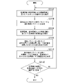
- FIG. 6 is a flowchart of a processing example of the robot remote control device 3 according to this embodiment.
- Step S101 The intention estimating unit 33 uses the acquired environmental sensor values to perform environment recognition, such as recognizing that three objects obj1 to obj3 are placed on a table.
- the intention estimation unit 33 estimates that the target object is the object obj3 based on the line-of-sight information included in the operator state information acquired from the HMD 5 .
- the intention estimating unit 33 may also perform estimation using information on the direction and inclination of the head included in the operator state information.
- the intention estimation unit 33 calculates the probability that each object is the target object (reach object probability).
- the intention estimation unit 33 calculates the probability based on, for example, line-of-sight information, the estimated distance between the target object and the gripping unit of the robot 2, the position and movement (trajectory) of the controller 6, and the like.
- the intention estimating unit 33 determines the position and movement of the arm (hand position, hand movement (trajectory), finger position, finger movement (trajectory), arm movement) included in the acquired operator state information. position, arm motion (trajectory)), and the position and motion of the head are compared with templates stored in the storage unit 37 to classify the motion. Estimates the intention of movement and the way of holding (grasping method). For example, the gripping method determining unit 34 determines the gripping method by referring to a template stored in the storage unit 37, for example. Note that the gripping method determination unit 34 may select a gripping method by inputting it into a learned model stored in the storage unit 37, for example. Note that the intention estimation unit 33 estimates the operator's motion intention using at least one of line-of-sight information, operator arm information, and head motion information. Note that the intention estimation unit 33 may also estimate the intention using the environmental sensor value.
- the gripping method determination unit 34 determines a gripping method for the robot 2 based on the estimated motion intention of the operator.
- the gripping method determining unit 34 calculates the amount of deviation between the positions of the operator's hands and fingers and the position of the gripping unit of the robot.
- the storage unit 37 stores, for example, a delay time or the like, which is the time required from the instruction to the operation of the driving unit 22, which is measured in advance.
- the gripping method determining unit 34 calculates the amount of deviation using the delay time stored in the storage unit 37, for example. Subsequently, the gripping method determination unit 34 corrects the amount of deviation between the positions of the operator's hands and fingers and the position of the gripping unit of the robot.
- the gripping method determining unit 34 calculates the current motion target value based on the sampling time of the robot control.
- the robot state image creation unit 35 creates a robot state image to be displayed on the HMD 5 based on the result of recognition and estimation by the intention estimation unit 33 and the result of calculation by the gripping method determination unit 34. .
- the robot state image also includes information about the processing that the robot remote control device 3 is about to perform, system state information, and the like.
- FIG. 7 is a diagram showing an example of a robot state image displayed on the HMD 5 according to this embodiment.
- Images g11 to g13 correspond to objects obj1 to obj3 placed on the table. Assume that the reach object probability in this case is 0.077 for the image g11, 0.230 for the image g12, and 0.693 for the image g13.
- Image g21 represents the actual position of the gripper of robot 2 .
- Image g22 represents the position input by the operator's controller 6.
- FIG. An image g23 represents the commanded position of the gripper of the robot 2 that has been corrected.
- the storage unit 37 stores shape data (for example, CAD (Computer Aided Design) data) of the gripping portion of the robot 2 and the like.
- the robot state image creation unit 35 uses the shape data of the gripping portion of the robot 2 and the like to generate an image of the gripping portion of the robot 2 and the like.
- the robot state image creating unit 35 creates a robot state image such as that shown in FIG. 7 by using, for example, the SLAM (Simultaneous Localization and Mapping) technique.
- SLAM Simultaneous Localization and Mapping
- the operator visually sees the actual position of the gripping portion of the robot 2 (image g21), the position that he is inputting (image g22), and the corrected position of the gripping portion of the robot 2 (image g23). Since it can be done, it becomes an assistant to the operator.
- the motion of the robot is corrected based on the intention of the operator, and the processing that the robot remote control device 3 is going to perform is presented to the operator as visual information, for example. can be done smoothly.
- the position information of the gripping portion is corrected based on the actual position of the gripping portion of the robot and the state of the operator. pickup can be realized.
- I to V are performed for remote control.
- the robot model, recognition results, information about the processing that the robot remote control device 3 is about to perform, information about the system status, etc. are presented on the HMD.
- the gripping method determination unit 34 selects the classification of the selected motion, the shape of the object, physical parameters such as estimated friction and weight of the object, and constraint conditions such as the torque that the robot 2 can output. , the contact point of the fingers of the robot 2 that can be grasped on the object is obtained. Then, the gripping method determining unit 34 performs a correction operation using, for example, the joint angles calculated from these as target values.
- the gripping method determining unit 34 when operating according to the target values, for example, adjusts the joint angles and torques of the fingers in real time so as to eliminate errors between the target values/parameter estimated values and the values observed by the sensors 27 of the robot 2. to control. As a result, according to the present embodiment, it is possible to stably and continuously hold the object without dropping it.
- the robot remote control device 3 may not be included in the robot 2 or may be an external device of the robot 2 . In this case, the robot 2 and the robot remote control device 3 may transmit and receive various information. Alternatively, the robot 2 may have some of the functional units of the robot remote control device 3 and the other functional units may be provided by an external device.
- the above-described robot 2 may be, for example, a bipedal robot, a stationary reception robot, or a working robot.
- the robot 2 is made to grip by remote control
- the present invention is not limited to this.
- the robot 2 is a bipedal walking robot
- the operator may remotely control walking of the robot 2 by attaching controllers to the legs.
- the robot 2 may, for example, detect object information such as an obstacle by image processing, and the operator may remotely operate the robot 2 to avoid the obstacle and walk.
- Detection of line-of-sight information and provision of the robot state image to the operator may be performed by, for example, a combination of a sensor and an image display device.
- a program for realizing all or part of the functions of the robot 2 and all or part of the functions of the robot remote control device 3 in the present invention is recorded on a computer-readable recording medium. All or part of the processing performed by the robot 2 and all or part of the processing performed by the robot remote control device 3 may be performed by loading the recorded program into the computer system and executing the program.
- the "computer system” referred to here includes hardware such as an OS and peripheral devices.
- the "computer system” shall include a system built on a local network, a system built on the cloud, and the like.
- computer-readable recording medium refers to portable media such as flexible discs, magneto-optical discs, ROMs and CD-ROMs, and storage devices such as hard discs incorporated in computer systems.
- computer-readable recording medium means a volatile memory (RAM) inside a computer system that acts as a server or client when a program is transmitted via a network such as the Internet or a communication line such as a telephone line. , includes those that hold the program for a certain period of time.
- RAM volatile memory
- the program may be transmitted from a computer system storing this program in a storage device or the like to another computer system via a transmission medium or by transmission waves in a transmission medium.
- the "transmission medium” for transmitting the program refers to a medium having a function of transmitting information, such as a network (communication network) such as the Internet or a communication line (communication line) such as a telephone line.
- the program may be for realizing part of the functions described above. Further, it may be a so-called difference file (difference program) that can realize the above-described functions in combination with a program already recorded in the computer system.
- FIG. 8 is a diagram showing an outline of the robot remote control system 1001 and an outline of work according to this embodiment.
- the operator Us is wearing an HMD (head mounted display) 1005 and a controller 1006, for example.
- Environmental sensors 1007 (1007a, 1007b) are installed in the working environment.
- the environment sensor 1007c may be attached to the robot 1002.
- the environment sensors 1007 (1007a, 1007b) include, for example, an RGB camera and a depth sensor as described later.
- the operator Us remotely operates the robot 1002 by moving the hand or fingers wearing the controller 1006 while viewing the image displayed on the HMD 1005 .
- FIG. 8 is a diagram showing an outline of the robot remote control system 1001 and an outline of work according to this embodiment.
- the operator Us is wearing an HMD (head mounted display) 1005 and a controller 1006, for example.
- Environmental sensors 1007 (1007a, 1007b) are installed in the working environment.
- the environment sensor 1007c may be attached to the robot 1002.
- the operator Us remotely operates the robot 1002 to grip the PET bottle obj on the table Tb and open the cap of the PET bottle, for example.
- the operator Us cannot directly view the motion of the robot 1002 , but can indirectly view the image of the robot 1002 through the HMD 1005 .
- the intention of the operator is estimated and estimated. Based on the results, the degree of freedom to be controlled by the operator is limited to support the operation.
- FIG. 9 is a block diagram showing a configuration example of a robot remote control system 1001 according to this embodiment.
- the robot remote control system 1001 includes a robot 1002 , a robot remote control device 1003 , an HMD 1005 , a controller 1006 and an environment sensor 1007 .
- the robot 1002 includes, for example, a control unit 1021, a drive unit 1022, a sound pickup unit 1023, a storage unit 1025, a power supply 1026, and a sensor 1027.
- the robot remote control device 1003 includes, for example, an information acquisition unit 1031, an intention estimation unit 1033, a control command generation unit 1034, a robot state image generation unit 1035, a transmission unit 1036, and a storage unit 1037.
- the HMD 1005 includes an image display unit 1051, a line-of-sight detection unit 1052 (operator sensor), a control unit 1054, and a communication unit 1055, for example.
- the HMD 1005 may include a sensor that detects, for example, the inclination of the operator's head.
- the controller 1006 includes, for example, a sensor 1061 (operator sensor), a control section 1062, a communication section 1063, and feedback means 1064.
- the environment sensor 1007 includes an imaging device 1071, a sensor 1072, and a communication unit 1073, for example.
- the robot remote control device 1003 and the HMD 1005 are connected via a wireless or wired network, for example.
- the robot remote control device 1003 and the controller 1006 are connected via a wireless or wired network, for example.
- the robot remote control device 1003 and the environment sensor 1007 are connected via a wireless or wired network, for example.
- the robot remote control device 1003 and the robot 1002 are connected via a wireless or wired network, for example.
- the robot remote control device 1003 and the HMD 1005 may be directly connected without going through a network.
- the robot remote control device 1003 and the controller 1006 may be directly connected without going through a network.
- the robot remote control device 1003 and the environment sensor 1007 may be directly connected without going through a network.
- the robot remote control device 1003 and the robot 1002 may be directly connected without going through a network.
- the HMD 1005 displays the robot state image received from the robot remote control device 1003 .
- the HMD 1005 detects the movement of the operator's line of sight and the like, and transmits the detected line-of-sight information (operator sensor value) to the robot remote control device 1003 .
- the image display unit 1051 displays the robot state image received from the robot remote control device 1003 under the control of the control unit 1054 .
- the line-of-sight detection unit 1052 detects the line-of-sight of the operator and outputs the detected line-of-sight information to the control unit 1054 .
- the control unit 1054 transmits line-of-sight information based on the line-of-sight information detected by the line-of-sight detection unit 1052 to the robot remote control device 1003 via the communication unit 1055 .
- the control unit 1054 causes the image display unit 1051 to display the state image of the robot transmitted by the robot remote control device 1003 .
- the communication unit 1055 receives the robot state image transmitted by the robot remote control device 1003 and outputs the received robot state image to the control unit 1054 .
- the communication unit 1055 transmits operator state information to the robot remote control device 1003 under the control of the control unit 1054 .
- the controller 1006 is, for example, a tactile data glove worn on the operator's hand.
- the controller 1006 detects operator arm information, which is information about the posture and position of the operator's arm such as orientation, movement of each finger, and movement of the hand, using the sensor 1061, and stores the detected operator arm information (operation sensor value) to the robot remote control device 1003 .
- the operator arm information includes the position and posture information of the hand, the angle information of each finger, the position and posture information of the elbow, and the information tracking the movement of each part. It contains a wide range of information.
- the sensor 1061 is, for example, an acceleration sensor, a gyroscope sensor, a magnetic force sensor, or the like. Note that the sensor 1061 includes a plurality of sensors, and tracks the movement of each finger using, for example, two sensors. The sensor 1061 detects operator arm information and outputs the detected operator arm information to the control unit 1062 .
- the control unit 1062 transmits operator arm information based on the detection result detected by the sensor 1061 to the robot remote control device 1003 via the communication unit 1063 .
- Control section 1062 controls feedback means 1064 based on the feedback information.
- the communication unit 1063 transmits operator arm information to the robot remote control device 1003 under the control of the control unit 1062 .
- the communication unit 1063 acquires feedback information transmitted by the robot remote control device 1003 and outputs the acquired feedback information to the control unit 1062 .
- the feedback means 1064 feeds back feedback information to the operator under the control of the control section 1062 .
- the feedback means 1064 is, for example, means for applying vibration (not shown), means for applying air pressure (not shown), or means for restraining hand movement ( (not shown), means for feeling temperature (not shown), means for feeling hardness or softness (not shown), or the like is used to feed back sensations to the operator.
- the environment sensor 1007 is installed at a position where, for example, the work of the robot 1002 can be photographed and detected.
- the environment sensor 1007 may be provided on the robot 1002 or may be attached to the robot 1002 .
- a plurality of environment sensors 1007 may be installed in the working environment and attached to the robot 1002 as shown in FIG.
- the environment sensor 1007 transmits the photographed image and the detected detection result (environment sensor value) to the robot remote control device 1003 .
- the imaging device 1071 is, for example, an RGB camera.
- the imaging device 1071 transmits the captured image to the robot remote control device 1003 via the communication unit 1073 .
- the positional relationship between the imaging device 1071 and the sensor 1072 is known.
- the sensor 1072 is, for example, a depth sensor.
- the sensor 1072 transmits the detected sensor value to the robot remote control device 1003 via the communication unit 1073 .
- the imaging device 1071 and the sensor 1072 may be distance sensors.
- the communication unit 1073 transmits the captured image and the sensor values detected by the sensor 1072 to the robot remote control device 1003 as environmental sensor information.
- the environment sensor 1007 may detect the position information of the object using the captured image and the sensor value, and transmit the detection result to the robot remote control device 1003 as the environment sensor information.
- the data transmitted by the environment sensor 1007 may be, for example, a point cloud having position information.
- the behavior of the robot 1002 is controlled according to the control of the control unit 1021 when it is not remotely controlled.
- the robot 1002 When the robot 1002 is remotely operated, its action is controlled according to the grasping plan information generated by the robot remote control device 1003 .
- the control unit 1021 controls the drive unit 1022 based on the control command output by the robot remote control device 1003 . Based on the information stored in the storage unit 1025, the control unit 1021 uses the image captured by the environment sensor 1007 and the detection result to notify the three-dimensional position, size, shape, etc. of the target object in the captured image. obtained by the method of Note that the control unit 1021 may perform speech recognition processing (speech segment detection, sound source separation, sound source localization, noise suppression, sound source identification, etc.) on the acoustic signal collected by the sound collection unit 1023 . If the result of voice recognition includes an action instruction for the robot, the control unit 1021 may control the action of the robot 1002 based on the action instruction by voice. The control unit 1021 generates feedback information and transmits the generated feedback information to the controller 1006 via the robot remote control device 1003 .
- speech recognition processing speech segment detection, sound source separation, sound source localization, noise suppression, sound source identification, etc.
- the driving section 1022 drives each section (arms, fingers, legs, head, torso, waist, etc.) of the robot 1002 under the control of the control section 1021 .
- the drive unit 1022 includes, for example, actuators, gears, artificial muscles, and the like.
- the sound pickup unit 1023 is, for example, a microphone array including a plurality of microphones.
- the sound pickup unit 1023 outputs the picked-up sound signal to the control unit 1021 .
- the sound pickup unit 1023 may have a speech recognition processing function. In this case, the sound pickup unit 1023 outputs the speech recognition result to the control unit 1021 .
- the storage unit 1025 stores, for example, programs and threshold values used for control by the control unit 1021, and temporarily stores voice recognition results, image processing results, control commands, and the like.
- the storage unit 1037 may also serve as the storage unit 1025 .
- the storage unit 1037 may also serve as the storage unit 1025 .
- a power supply 1026 supplies power to each part of the robot 1002 .
- Power source 1026 may include, for example, a rechargeable battery and charging circuitry.
- the sensors 1027 are, for example, acceleration sensors, gyroscope sensors, magnetic force sensors, joint encoders, and the like. Sensors 1027 are attached to each joint, head, etc. of the robot 1002 .
- the sensor 1027 outputs the detected result to the control unit 1021 , the intention estimation unit 1033 , the control command generation unit 1034 and the robot state image generation unit 1035 .
- the robot remote control device 1003 detects the operator based on the operator detection value detected by the operator sensors (the line-of-sight detection unit 1052 of the HMD 1005 and the sensor 1061 of the controller 1006) and the environment sensor value detected by the environment sensor 1007. A motion intention is estimated and a control command for the robot 1002 is generated.
- the information acquisition unit 1031 acquires line-of-sight information from the HMD 1005, acquires operator arm information from the controller 1006, and sends the acquired line-of-sight information and operator arm information to the intention estimation unit 1033 and the robot state image creation unit 1035. Output.
- the information acquisition unit 1031 acquires environment sensor information from the environment sensor 1007 and outputs the acquired environment sensor information to the intention estimation unit 1033 and the robot state image creation unit 1035 .
- the information acquisition unit 1031 acquires the detection result detected by the sensor 1027 and outputs the acquired detection result to the intention estimation unit 1033 and the robot state image creation unit 1035 .
- the intention estimation unit 1033 Based on the environment sensor information acquired by the information acquisition unit 1031, the intention estimation unit 1033 obtains information about the target object (robot environment sensor values) (name of the target object, position of the target object, inclination of the target object in the vertical direction, etc.). to estimate Note that the intention estimation unit 1033 performs image processing (edge detection, binarization processing, feature amount extraction, Image enhancement processing, image extraction, pattern matching processing, etc.) are performed to estimate the name of the target object. The intention estimation unit 1033 estimates the position of the target object, the tilt angle in the vertical direction, and the like based on the result of the image processing and the detection result of the depth sensor.
- image processing edge detection, binarization processing, feature amount extraction, Image enhancement processing, image extraction, pattern matching processing, etc.
- the intention estimation unit 1033 estimates the target object, for example, also using the operator's line-of-sight information detected by the HMD 1005 .
- the intention estimation unit 1033 estimates the motion intention of the operator based on the line-of-sight information and the operator arm information acquired by the information acquisition unit 1031 and the information on the target object. The intention of the operator and the estimation method will be described later.
- the control command generation unit 1034 generates a control command for gripping an object based on the result estimated by the intention estimation unit 1033, the detection result detected by the sensor 1027, and the image captured by the environment sensor 1007 and the detection result.
- the control command generator 1034 generates a control command by restricting the degree of freedom to be controlled by the operator and the controllable range, that is, by reducing the degree of freedom of motion of the operator, as will be described later.
- Control command generator 1034 outputs the determined control command information to control unit 1021 .
- the robot state image creation unit 1035 creates a robot state image to be displayed on the HMD 1005 based on the control command information generated by the control command generation unit 1034 .
- the transmission unit 1036 transmits the robot state image created by the robot state image creation unit 1035 to the HMD 1005 .
- the transmission unit 1036 acquires feedback information output by the robot 1002 and transmits the acquired feedback information to the controller 1006 .
- the storage unit 1037 stores the positional relationship between the imaging device 1071 of the environment sensor 1007 and the sensor 1072 .
- the storage unit 1037 stores information that limits the degree of freedom to be controlled by the operator, that is, the controllable range, for each work content.
- the storage unit 1037 stores model images to be compared in pattern matching processing of image processing.
- the storage unit 1037 stores programs used for controlling the robot remote control device 1003 . Note that the program may be on the cloud or network.
- FIG. 10 is a diagram showing an example of a state in which the HMD 1005 and controller 1006 are worn by the operator.
- the operator Us wears the controller 1006a on his left hand, the controller 1006b on his right hand, and the HMD 1005 on his head.
- the HMD 1005 and the controller 1006 shown in FIG. 10 are examples, and the mounting method, shape, and the like are not limited to these.
- FIG. 11 is a diagram showing an outline of intention estimation and control command generation processing according to the present embodiment.
- the robot remote control device 1003 acquires line-of-sight information from the HMD 1005 , operator arm information from the controller 1006 , environment sensor information from the environment sensor 1007 , and detection results detected by the sensor 1027 .
- Information obtained from the robot 1002 is information such as detection values of motor encoders provided at each joint of the robot 1002 .
- Information obtained from the environment sensor 1007 includes images captured by the RGB camera, detection values detected by the depth sensor, and the like.
- the intention estimation unit 1033 estimates the operator's action intention based on the acquired information and the information stored in the storage unit 1037 .
- the intention of the operator is, for example, the object to be operated, the content of the operation, and the like.
- the content of the operation is, for example, opening the lid of a plastic bottle.
- the control command generation unit 1034 Based on the information obtained as a result of the estimation by the intention estimation unit 1033, the control command generation unit 1034 limits the degree of freedom to be controlled by the operator and the controllable range according to the target object and work content. Then, the control command generation unit 1034 generates a control command based on the result estimated by the intention estimation unit 1033 .
- FIGS. 12 and 13 are the xyz axes in the robot world.
- the robot remote control device 1003 of this embodiment performs the following restrictions on the degree of freedom and correction of hand targets based on xyz in the robot world.
- FIG. 12 is a diagram showing a case where the operator's intention is to open the cap of the PET bottle.
- the intention estimation unit 1033 estimates the target object Obj 1001 based on the tracking result of the operator's hand, the operator's line-of-sight information, the image captured by the environment sensor 1007, and the detection result. As a result, the intention estimation unit 1033 estimates that the operation target Obj 1001 is the "PET bottle" based on the acquired information. Further, the intention estimation unit 1033 detects, for example, the vertical direction of the PET bottle and the inclination of the PET bottle in the vertical direction with respect to, for example, the z-axis direction, based on the image captured by the environment sensor 1007 and the detection result.
- the intention estimation unit 1033 estimates the operation content based on the tracking result of the operator's hand, the operator's line of sight information, the image captured by the environment sensor 1007, and the detection result. As a result, based on the acquired information, the intention estimation unit 1033 estimates that the operation content is the action of “opening the cap of the PET bottle”.
- the operator needs to remotely operate the gripper 1221 of the robot 1002 so that it is in the vertical direction of the PET bottle and also remotely operates it to open the lid. there were.
- the conventional method has a problem that the operator himself/herself is required to have a high level of operation skill.
- the robot remote control device 1003 replaces the control target value generation for some of the six degrees of freedom depending on the situation, thereby limiting the degree of freedom that the operator should control. .
- the robot remote control device 1003 controls and assists the gripper 1221 of the robot 1002 so that the gripper 1221 stays in the vertical direction. As a result, the operator can concentrate on instructing the rotation of the cap without worrying about the inclination of the PET bottle.
- FIG. 13 is a diagram showing a case where the operator's intention is to grab the box.
- the intention estimation unit 1033 estimates that the operation target Obj 1002 is a "box" based on the acquired information. Next, based on the acquired information, the intention estimation unit 1033 estimates that the operation content is an action of “grabbing a box”.
- the robot remote control device 1003 assists the position of the operation target Obj1002 on the xy plane and the rotation around the xyz axis by controlling the gripper 1221. This allows the operator to concentrate on instructing the translational movement of the z-axis position.
- the target object, work content, assisting content (degree of freedom), etc. shown in FIGS. 12 and 13 are examples, and the target object, work content, and assisting content are not limited to these.
- the content of the assistance may be anything that corresponds to the target object or the content of the work.
- FIG. 14 is a diagram showing an example of information stored by the storage unit 1037 according to this embodiment.
- the storage unit 1037 stores the target object, the work content, the degree of freedom restricted to the operator (the degree of freedom reinforced by the robot 1002), and the degree of freedom operable by the operator. are stored in association with each other. Note that the example shown in FIG. 14 is only an example, and other information may also be associated and stored.
- the operator's operating environment and the robot operating environment may be calibrated when the robot 1002 is activated.
- the robot remote control device 1003 determines the gripping position based on the gripping force of the robot 1002, the frictional force between the object and the gripping part, and the like, taking into account the gripping position error during gripping. You may make it
- FIG. 15 is a diagram showing an example of correction of the hand target of the gripping position with the assistance of the robot remote control device 1003.
- the shape of the target object g1021 to be grasped is a substantially rectangular parallelepiped.
- the control command generator 1034 estimates a pattern to assist each object. The estimation method is performed, for example, by matching with a database stored in the storage unit 1037 or by machine learning. After estimating the auxiliary pattern, the control command generator 1034 corrects the direction by performing vector calculation (cross product/inner product) between the coordinate system of the object and the hand coordinate system of the robot.
- control command generation unit 1034 performs correction and command value generation by an end-to-end machine learning method that directly generates a correction command value from sensor information, including direction correction by vector calculation, for example.
- the robot remote control device 1003 estimates the target object and the work content, and corrects the hand target to a position that is easier to grip, so that the operator can easily give instructions.
- the intention estimation unit 1033 or the storage unit 1037 receives, for example, line-of-sight information, operator arm information, environmental sensor information, and detection results detected by the sensors of the robot 1002, and learns the target object and operation details as teacher data.
- the intention estimation model may be provided.
- the intention estimation model may be provided on the cloud.
- the intention estimation unit 1033 may input the acquired information into the intention estimation model to estimate the intention of the operator.
- the intention estimation unit 1033 may input the acquired information into the intention estimation model to estimate at least one of the target object and the work content.
- the intention estimation unit 1033 may estimate the intention of the operator by probabilistic inference using the acquired information.
- the intention estimation unit 1033 may estimate at least one of the target object and the work content by probabilistic inference using the acquired information.
- FIG. 16 is a flow chart of an example of the processing procedure of the robot 1002 and the robot remote control device 1003 according to this embodiment.
- Step S ⁇ b>1001 The information acquisition unit 1031 acquires line-of-sight information from the HMD 1005 and operator arm information from the controller 1006 .
- Step S1002 The information acquisition unit 1031 acquires environment sensor information from the environment sensor 1007.
- the intention estimation unit 1033 estimates the operator's intention including the object to be grasped and the work content based on the acquired line-of-sight information, operator arm information, and environment sensor information.
- Step S1004 Based on the estimated intention of the operator and the information stored in the storage unit 1037, the control command generation unit 1034 generates the degree of freedom assisted by the robot remote control device 1003, that is, the operator's operation instruction. determines the limits on the degrees of freedom of Note that the control command generation unit 1034 reduces the degree of freedom of the operator's motion and generates the control command by generating an appropriate control command for a part of the degree of freedom of the operator's motion.
- Step S1005 The control command generation unit 1034 corrects the target hand position to be gripped based on the arm movement information included in the acquired operator arm information and the degree of freedom to be restricted determined in step S1004. .
- Step S1006 Based on the operator arm information acquired by the information acquisition unit 1031, the result estimated by the intention estimation unit 1033, and the gripping position corrected by the control command generation unit 1034, the robot state image generation unit 1035 , create a robot state image to be displayed on the HMD 1005 .
- Step S1007 The control command generator 1034 generates a control command based on the corrected target hand position to be gripped.
- Step S1008 Based on the control command generated by the control command generation unit 1034, the control unit 1021 controls the driving unit 1022 to drive the grasping unit of the robot 1002 and the like. After the processing, the control unit 1021 returns to the processing of step S1001.
- the processing procedure shown in FIG. 16 is an example, and the robot remote control device 1003 may process the above-described processing in parallel.
- the image displayed on the image display unit 1051 of the HMD 1005 is, for example, an image as shown in FIG.
- the robot state image may not include the image of the operator's input g1011.
- the robot state image creation unit 1035 presents an assist pattern with characters or displays a rectangle, an arrow, or the like on the HMD 1005 to limit the degree of freedom and present the details of robot assistance to the operator. may
- the operator gives a work instruction while looking at the robot state image displayed on the HMD 1005, for example, when opening the cap of a PET bottle, the operator can do so without worrying about aligning the gripping portion with the vertical direction of the PET bottle. You can concentrate on the work instructions for opening the lid.
- the robot remote control device 1003 judges the work content and the target object through sensor information installed in the robot 1002, the environment, and the operator.
- the degree of freedom to be controlled by the operator is limited. That is, in the present embodiment, the degree of freedom to be controlled by the operator is reduced by automatically generating appropriate control commands for some of the degrees of freedom.
- limiting of the degree of freedom mentioned above is an example, and it is not restricted to this.
- a limited degree of freedom does not mean that the operator cannot completely control the degree of freedom, but also includes a limited operable area.
- the robot remote control device 1003 does not limit the degree of freedom when the distance from the target object is outside the predetermined range, but limits the degree of freedom when the distance is within the predetermined range from the target object. good too.
- the predetermined range is, for example, a range of ⁇ 1001 m of the translational x-axis.
- the robot remote control device 1003 restricts the degree of freedom according to the work content even if the work content is different. Moreover, when there are a plurality of work contents, the robot remote control device 1003 may change the restriction of the degree of freedom each time the work contents change. For example, when a plurality of objects are placed on a table, and one PET bottle is grasped from among them and then the lid of the PET bottle is opened, the first degree of freedom restriction in the gripping step is to open the lid. The robot remote control device 1003 sets the second degree of freedom restriction when allowing the robot to move.
- the robot remote control device 1003 limits the degree of freedom and corrects the hand target for each gripping part.
- the above-described robot 1002 may be, for example, a bipedal walking robot, a stationary reception robot, or a working robot.
- Detection of line-of-sight information and provision of the robot state image to the operator may be performed by, for example, a combination of a sensor and an image display device.
- a program for realizing all or part of the functions of the robot 1002 and all or part of the functions of the robot remote control device 1003 in the present invention is recorded on a computer-readable recording medium, and this recording medium All or part of the processing performed by the robot 1002 and all or part of the processing performed by the robot remote control device 1003 may be performed by loading and executing the recorded program into the computer system.
- the "computer system” referred to here includes hardware such as an OS and peripheral devices.
- the "computer system” shall include a system built on a local network, a system built on the cloud, and the like.
- computer-readable recording medium refers to portable media such as flexible discs, magneto-optical discs, ROMs and CD-ROMs, and storage devices such as hard discs incorporated in computer systems.
- computer-readable recording medium means a volatile memory (RAM) inside a computer system that acts as a server or client when a program is transmitted via a network such as the Internet or a communication line such as a telephone line. , includes those that hold the program for a certain period of time.
- RAM volatile memory
- the program may be transmitted from a computer system storing this program in a storage device or the like to another computer system via a transmission medium or by transmission waves in a transmission medium.
- the "transmission medium” for transmitting the program refers to a medium having a function of transmitting information, such as a network (communication network) such as the Internet or a communication line (communication line) such as a telephone line.
- the program may be for realizing part of the functions described above. Further, it may be a so-called difference file (difference program) that can realize the above-described functions in combination with a program already recorded in the computer system.
- FIG. 17 is a schematic block diagram showing a configuration example of the robot system S2001 according to this embodiment.
- the robot system S2001 is a control system that can control the motion of the robot 2020 in accordance with the motion of an operator who is a user.
- the robot system S2001 is also a control system that controls the motion of the robot 2020 according to the operation.
- the robot 2020 includes an effector (also called an end-effector, end effector, robot hand, hand effector, effector, etc.).
- An effector is a member that mechanically acts and influences another object.
- the effector has multiple fingers and includes a mechanism that allows it to grasp or release other objects. The individual fingers are operable in response to movement of the operator's corresponding fingers. As a result, various operations are realized.
- the robot system S2001 estimates the operation status of the robot 2020 based on the environment information indicating the operation environment of the robot 2020 and the operation information indicating the operation status. As will be described later, the robot system S2001 may also use the driving state information acquired from the driving sensor 2026, the line-of-sight information of the operator, and the like when estimating the operation state.
- the robot system S2001 generates a control command for moving the effector of the robot 2020 to a target position based on characteristic parameters indicating control characteristics corresponding to the operating situation.
- the robot system S2001 controls the motion of the robot 2020 based on the generated control commands.
- the operating situation mainly includes the mode of operation performed by the robot 2020, that is, the task or operation mode.
- the action status may include, for example, the type of work to be performed, the positional relationship with the object involved in the work, the type or characteristics of the object, etc. as elements.
- An operational situation may be defined including any element or combination of any element. Even if the operation information is common, the target position to which the effector of the robot 2020 is moved may differ depending on the operating situation.
- the robot system S2001 includes a robot 2020, a display device 2050, an operation device 2070, and an environment information acquisition section 2080.
- Robot 2020 includes one or more manipulators.
- Manipulators are also called robotic arms.
- Each manipulator comprises a plurality of segments, which are interconnected.
- the multiple segments include an effector.
- the effector is a member that is connected to one end of the manipulator and that contacts and acts on an object.
- the motion mechanism of the robot 2020 includes a joint for each segment pair including two segments among the plurality of segments, and an actuator for each joint. By changing the angle formed between each two segments by the actuator, the position of the effector can be moved.
- the number of manipulators is mainly one (single-arm type), but it may be two or more.
- the robot 2020 may be a stationary type that is fixed at a predetermined position, or a movable type that can move its own position. The following description mainly assumes that the robot 2020 is of a stationary type.
- the control device 2030 of the robot 2020 is connected to the display device 2050, the operation device 2070, and the environment information acquisition unit 2080 wirelessly or by wire so that various information can be input/output.
- the display device 2050 and the operation device 2070 may be located in a space physically separated from the robot 2020 and the environment information acquisition section 2080 . In that case, the display device 2050 and the operation device 2070 may be configured as a remote control system connected to the control device 2030 via a communication network.
- Robot 2020 includes drive 2024 , drive sensor 2026 , power supply 2028 and controller 2030 .
- the drive unit 2024 has an actuator for each joint and operates according to control commands input from the drive control unit 2040 of the control device 2030 .
- Each actuator corresponds to a so-called motor, and changes the angle formed by two segments connected to itself according to the target value of the amount of drive indicated by the control command.
- the drive sensor 2026 detects the drive state of the robot 2020 by the drive unit 2024 and outputs drive state information indicating the detected drive state to the control device 2030 .
- the drive sensor 2026 includes, for example, a rotary encoder that detects the angle formed by two segments for each joint.
- a power supply 2028 supplies power to each component included in the robot 2020 .
- the power source 2028 includes, for example, power terminals, a secondary battery, and a voltage converter.
- a power supply terminal enables a power line to be connected, is supplied with power from the outside, and supplies the supplied power to a secondary battery or a voltage converter.
- a secondary battery stores power supplied using a power supply terminal. The secondary battery can supply power to each component via the voltage converter.
- the voltage converter converts the voltage of the power supplied from the power supply terminal or the power supply terminal into a predetermined voltage required by each component, and supplies the power obtained by converting the voltage to each component.
- FIG. FIG. 18 is a block diagram showing a functional configuration example of part of the control device 2030 according to this embodiment.
- the control device 2030 includes an information acquisition section 2032 , an operating state estimation section 2034 , a target position estimation section 2036 , a control command generation section 2038 , a drive control section 2040 , a communication section 2042 and a storage section 2044 .
- the information acquisition unit 2032 acquires various types of information regarding the status of the operator and the status of the robot 2020 . For example, the information acquisition unit 2032 acquires line-of-sight information and first operator action information from the display device 2050 .
- the line-of-sight information and the first operator action information constitute operator information indicating the operator's situation.
- the line-of-sight information is information indicating the line-of-sight direction of at least one eye of the operator at a certain time.
- the first operator motion information is information indicating the motion of the operator's head. The movement of the head is represented by the direction and position of the head for each time.
- line-of-sight information and first operator action information may be collectively referred to as operator information.
- the information acquisition unit 2032 acquires second operator action information from the operation device 2070 .
- the second operator motion information is information indicating a body motion related to an operation by the operator.
- the second operator action information constitutes operation information indicating the operation status of the robot 2020 .
- the second operator motion information includes information mainly indicating motions of hands as body parts of the operator.
- Hand motion includes motion of at least two fingers.
- the second operator motion information may include information indicating wrist motions in addition to hand motions.
- the motion of the wrist may be represented using a representative position of the wrist, and may further include information on its posture.
- the motion of the body part is expressed using information on the position of the body part for each time.
- the second operator action information may be referred to as operation information.
- Information acquisition section 2032 acquires environment information from environment information acquisition section 2080 .
- Environment information indicates the operating environment of the robot 2020 .
- the environment information includes image data representing an image representing the operating environment of the robot 2020 and distance data representing distances to objects distributed in the operating environment of the robot 2020 .
- the information acquisition unit 2032 acquires drive state information from the drive sensor 2026 .
- the drive state information can also be regarded as posture information indicating the posture of the robot 2020 .
- the time series of the drive state information at each time corresponds to robot motion information indicating the motion of the robot 2020 .
- the information acquisition unit 2032 stores various acquired information in the storage unit 2044 .
- the motion state estimation unit 2034 reads the latest environment information and operation information at that time from the storage unit 2044, and estimates the motion state of the robot 2020 based on the read environment information and operation information.
- the motion state estimation unit 2034 uses, for example, a predetermined machine learning model to estimate the motion state of the robot 2020 .
- the environment information and the operation information are input as input information to the action situation estimation unit 2034, the reliability of the known action situation corresponding to the input information is set to 1, and the reliability of the other action situation candidates is set as output information.
- a parameter set learned using training data is set in advance so that output information with a reliability of 0 can be obtained.
- the training data consists of many pairs of input information and known output information.
- the parameter set is learned such that the difference between the estimated output information estimated from the input information and the known output information as a whole training data is minimized.
- the reliability for each operating situation obtained from the machine learning model can be defined as a real value between 0 and 1.
- the action situation estimating unit 2034 can identify, as the action situation of the robot 2020, the action situation candidate whose reliability calculated for each action situation candidate is higher than a predetermined reliability and maximizes.
- an action situation for example, approaching an object (target object) existing in the direction closest to the direction of action of the hand indicated by the operation information at that time, among a plurality of objects present in the action environment of the robot 2020;
- the mode of action eg, grasp, release, friction, etc.
- the motion state estimation unit 2034 may read the latest operator information at that time from the storage unit 2044 and estimate the motion state of the robot 2020 based on the operator information in addition to the environment information and operation information. .
- the operator information indicates the line-of-sight direction in consideration of the movement of the operator's head. Therefore, when estimating the operating situation, the direction in which an event of interest to the operator occurs is further taken into account according to the operator information.
- the motion situation estimation unit 2034 outputs the reliability of the known motion situation corresponding to the input information as 1. , and the parameter set learned as described above is set in advance using the training data so as to obtain output information with a reliability of 0 for other motion situation candidates.
- the motion state estimation unit 2034 may read the latest drive state information at that time from the storage unit 2044 and further estimate the motion state of the robot 2020 based on the drive state information.
- the drive state information indicates the posture of the robot 2020 and its change over time. Therefore, the pose of the robot 2020 is further taken into consideration when estimating the motion situation.
- the motion situation estimation unit 2034 outputs the reliability of the known motion situation corresponding to the input information as 1. , and the parameter set learned as described above is set in advance using the training data so as to obtain output information with a reliability of 0 for other motion situation candidates.
- the operating state estimation unit 2034 determines characteristic parameters corresponding to the estimated operating state.
- a characteristic parameter is a parameter relating to the control characteristic for the operation of the effector.
- the characteristic parameter includes, for example, a convergence determination parameter, a weighting factor for each factor of the objective function, or a combination thereof.
- the storage unit 2044 stores in advance a characteristic parameter table indicating characteristic parameters for each operating situation.
- the operating state estimator 2034 refers to the characteristic parameter table, identifies the characteristic parameter corresponding to the estimated operating state, and outputs the identified characteristic parameter to the control command generator 2038 .
- a convergence determination parameter is a parameter that indicates a convergence determination condition for determining whether or not the position of the effector has converged to the target position.
- the strength of the convergence determination condition corresponds to the degree of constraint of the position to be converged (in this application, sometimes referred to as "convergence position") with respect to the target position, in other words, the accuracy with respect to the target position.
- a convergence determination parameter for example, a threshold of distance from the target position can be used. A smaller threshold for the distance from the target position indicates a stronger convergence determination condition.
- the motion state estimation unit 2034 may set a convergence determination parameter indicating a stronger convergence determination condition for a motion state that requires more followability of the position of the effector to be controlled.
- the followability means the property of being able to accurately control the position of the effector with respect to the target position, or the property requiring accurate control, that is, accuracy.
- Such operation situations include, for example, a situation in which a delicate object is installed in the effector and is sufficiently close to the target position, a situation in which the operation instructed by the operation information is delicate, and the like.
- Inverse kinematics calculation is an analysis method for determining the displacement of each joint from a target position, that is, one or both of angle and angular acceleration, and is also called inverse kinematics analysis.
- the inverse dynamics calculation determines the driving force of each joint to realize the motion of each joint (that is, the time change of one or both of the angle and angular acceleration) in a link mechanism consisting of multiple connected segments. It is an analytical technique, also called inverse dynamics analysis. Therefore, inverse kinematics calculation is also closely related to inverse dynamics calculation.
- characteristic parameters related to inverse kinematics calculation may include characteristic parameters related to inverse dynamics calculation.
- the motion state estimation unit 2034 may set a convergence determination parameter that indicates a weaker convergence determination condition (for example, distance from the target position) in a motion state that allows more flexibility in the position of the effector to be controlled.
- Flexibility refers to the property of allowing the position of the effector to deviate from the target position. Flexibility refers to the property of being reliably controllable, ie safety. Operating situations that allow for flexibility include, for example, multiple objects distributed around the path to the target location.
- the objective function is used in the inverse kinematics calculation to numerically obtain the optimum solution for the motion of the robot 2020 using a known method (optimization problem).
- the objective function is a function that quantitatively indicates the magnitude of the load for moving the effector to the target position, includes multiple types of factors, and is constructed by synthesizing these factors.
- a weighting factor indicates the contribution of each factor to the objective function.
- a load means a cost related to control.
- the plurality of factors includes, as one factor, the magnitude of the control error for each time.
- the magnitude of the control error is represented, for example, by the magnitude (distance) of the error between the final target position and convergence.
- Control is performed such that the greater the weighting factor for the control error, the higher the followability of the effector to the target position.
- the objective function includes the arrival time of the effector from the current position to the convergence position, the magnitude of the jerk from the present position to the convergence position, the amount of electric power from the present to the convergence position, and the robot 2020 to the convergence position. , the magnitude of the difference between the current posture of the robot 2020 and the posture of the robot 2020 at the time when the effector is positioned at the convergence position, or a combination thereof may be included as factors.
- optimization includes searching for a solution that makes the function value of the objective function smaller, and is not limited to absolutely minimizing the function value. Therefore, the function value may temporarily increase.
- the motion state estimating unit 2034 may set a larger weighting factor for the control error in motion states that require more followability of the position of the effector to be controlled.
- the motion state estimating section 2034 may set the weighting factor for the control error to be smaller in a motion state in which more flexibility in the position of the effector to be controlled is allowed.
- the motion state estimating unit 2034 may set the weighting factor for the magnitude of the jerk to be larger in a motion state that requires continuity in the position of the effector to be controlled.
- the operating state estimation unit 2034 determines drive control parameters corresponding to the estimated operating state.
- the drive control parameters are parameters relating to control characteristics for driving each segment that constitutes the robot 2020 .
- the drive control parameter is used when the controller forming the drive control unit 2040 determines the operation amount for the actuator that drives each joint.
- the storage unit 2044 stores in advance a drive control parameter table indicating drive control parameters for each operating situation.
- the operating state estimation unit 2034 refers to the drive control parameter table, specifies drive control parameters corresponding to the estimated operating state, and outputs the specified drive control parameters to the drive control unit 2040 .
- the controller is a PID (Proportional-Integral-Differential) controller
- the drive control parameters include proportional gain, integral gain, and differential gain.
- the proportional gain is a gain for calculating a proportional term, which is one component of the manipulated variable, by multiplying the difference between the target value and the output value at that point in time (current).
- the integral gain is a gain for calculating an integral term, which is another component of the manipulated variable, by multiplying the integral value of the deviation up to that point.
- the differential gain is a gain for calculating a differential term, which is another component of the manipulated variable, by multiplying the differential value of the deviation at that time.
- the operating condition estimating unit 2034 may determine individual gains, for example, such that the differential gain is relatively larger in an operating condition requiring followability than other types of gains.
- the motion situation estimator 2034 determines individual gains, for example, such that the more flexible the motion situation is, the larger the integral gain is relative to other types.
- the target position estimation unit 2036 reads the latest environment information and operation information at that time, and estimates the target position of the effector of the robot 2020 based on the read environment information and operation information.
- Target position estimation section 2036 outputs target position information indicating the estimated target position to control command generation section 2038 .
- the target position estimator 2036 uses, for example, a machine learning model to estimate the target position. In order to distinguish from the machine learning model in the motion situation estimation unit 2034, the machine learning model in the motion situation estimation unit 2034 and the machine learning model in the target position estimation unit 2036 are called a first machine learning model and a second machine learning model, respectively.
- a learned parameter set is provided in advance so as to obtain output information related to the target position corresponding to the input information. be set.
- the target position a position on the surface of the object that is empirically likely to be acted upon by the effector is set.
- the target position can depend on the shape of the object. For a vertically elongated cylinder whose height is greater than its diameter, the target position is the position closest to the effector among the cross-sections at the center of the base, the center of the surface, and the midpoint in the height direction. may become more likely.
- the output information from the machine learning model may be information indicating the coordinates of the target position, but is not limited to this.
- the output information may include information indicating, for example, the object for which the target position is set, the type, shape, and direction of the object, and the position on the object where the target position is set.
- the target position estimator 2036 can determine the coordinates of the target position from the output information.
- the target position estimation unit 2036 may read the latest operator information at that time from the storage unit 2044 and estimate the target position based on the operator information in addition to the environment information and operation information. Therefore, the target position is estimated in consideration of the direction in which the event of interest to the operator has occurred based on the operator information. However, when operator information is input as input information to the machine learning model in addition to environment information and operation information, the target position estimation unit 2036 obtains the coordinate values of the target position corresponding to the input information as output information. A learned parameter set is set in advance.
- the target position estimation unit 2036 does not necessarily have to estimate the target position using the second machine learning model. For example, if the action situation notified by the action situation estimation unit 2034 is an action situation that does not involve continuous translational motion of the effector, the target position estimation unit 2036 calculates the target position using the second machine learning model. No guess. Such operating conditions include, for example, stationary, rotating, grasping and releasing objects, friction on object surfaces, and the like. When the target position is not estimated using the second machine learning model, the target position estimation unit 2036 may adopt the position of the operator's hand indicated by the operation information as the target position. The target position estimation unit 2036 can use mathematical models such as neural networks and random forests as the first machine learning model and the second machine learning model.
- the control command generator 2038 generates an action command for moving the effector from the current position toward the target position indicated by the target position information input from the target position estimator 2036 .
- "Towards a target position” or “towards a target position” implies that the goal is to move to the target position, but that reaching the target position is not guaranteed.
- the control command generation unit 2038 can read the drive state information stored in the storage unit 2044 and calculate the current position of the effector based on the angles of each joint and the dimensions of each segment indicated by the drive state information.
- the control command generator 2038 can calculate the velocity of the effector based on the angular velocity of each joint in addition to the angle of each joint and the dimension of each segment indicated by the drive state information.
- the control command generation unit 2038 performs known inverse kinematics calculations based on the characteristic parameters and drive state information (robot motion information) input from the motion state estimation unit 2034, and performs each effector so as to move the effector to the convergence position. Determine the angle of the joint.
- the control command generation unit 2038 outputs to the drive control unit 2040 an action command (joint command) indicating the determined angle of each joint (joint angle).
- the control command generation unit 2038 determines any position within the region indicated by the convergence determination parameter from the target position as the convergence position in the inverse kinematics calculation. You can stop moving. When determining whether or not the current position of the effector has converged, the control command generation unit 2038 determines, for example, whether the current position of the effector is within a predetermined distance threshold indicated by the characteristic parameter from the target position. determine whether When determining that the position of the effector has converged, the control command generation unit 2038 generates a control command indicating operation stop and outputs it to the drive control unit 2040 .
- the drive control unit 2040 stops updating and fixes the target values for the individual joints when a control command indicating motion stop is input from the control command generation unit 2038 .
- the control command generation unit 2038 may impose a constraint condition that the velocity of the effector is zero, or the drive control unit 2040 may impose a constraint condition that the angular velocity of each joint is zero.
- the control command generation unit 2038 When the convergence characteristic parameter includes a weighting factor for each factor of the objective function, the control command generation unit 2038 performs the inverse kinematics calculation based on the objective function synthesized using the weighting factors and the corresponding factors. Perform optimization calculations.
- the objective function is calculated, for example, as the sum (weighted sum) of the product of a factor and its weighting factor.
- the control command generator 2038 may recursively calculate the angle of each joint so that the objective function representing the load generated until the effector reaches the target position or the convergence position is minimized. .
- control command generation unit 2038 may adopt the position of the hand indicated by the operation information as the target position.
- the control command generation unit 2038 performs inverse kinematics calculation to generate a motion command having the angle of each joint as a target value for moving the effector from the current position toward the adopted target position.
- the drive control unit 2040 operates based on the control command input from the control command generation unit 2038, the drive control parameters input from the operation state estimation unit 2034, and the drive state information (robot operation information) read from the storage unit 2044. Determine the drive command. More specifically, the drive control unit 2040 includes a controller that calculates a manipulated variable for controlling the angle of each joint indicated by the control command as a target value, and determines a control command that indicates the calculated manipulated variable. be done. Drive control unit 2040 outputs the determined control command to drive unit 2024 . The controller uses the angle indicated by the drive state information as an output value, and calculates the manipulated variable by applying the drive control parameter to the deviation between the target value and the output value according to the control method set in the controller. The PID controller calculates the sum of multiplied values obtained by multiplying the deviation, the time integral value of the deviation, and the time differential value of the deviation by the proportional gain, the integral gain, and the differential gain, respectively, as the manipulated variable.
- the communication unit 2042 wirelessly or wiredly transmits and receives various information between each component of the robot 2020 and other components (that is, the display device 2050, the operation device 2070, and the environment information acquisition unit 2080). .
- the communication unit 2042 includes, for example, an input/output interface, a communication interface, and the like.
- the storage unit 2044 temporarily or permanently stores data used for various processes in the control device 2030, various data acquired by the control device 2030, and the like.
- the storage unit 2044 includes storage media such as RAM (Random Access Memory) and ROM (Read Only memory), for example.
- the display device 2050 includes a display section 2052 , a line-of-sight detection section 2054 , a motion detection section 2056 , a control section 2058 and a communication section 2060 .
- the display device 2050 may be configured as a head-mounted display (HMD) including a support member that can be worn on the head of the operator who is the user.
- HMD head-mounted display
- the display unit 2052 receives image data from the environment information acquisition unit 2080 via the control device 2030 and using the communication unit 2060 .
- the display unit 2052 displays an image showing the operating environment of the robot 2020 based on the received image data.
- the display unit 2052 may be arranged at a position where the screen faces the front of both eyes.
- the line-of-sight detection unit 2054 includes a line-of-sight sensor that detects the line-of-sight direction of one or both eyes of the operator.
- the line-of-sight detection unit 2054 transmits line-of-sight information indicating the line-of-sight direction detected at each time to the control device 2030 using the communication unit 2060 .
- the line-of-sight detection unit 2054 may be arranged at a position exposed to at least one eye when worn on the operator's head.
- the motion detection unit 2056 detects a motion of the operator's head, and transmits first operator motion information indicating the detected motion to the control device 2030 using the communication unit 2060 .
- the motion detection unit 2056 includes, for example, an acceleration sensor for detecting the motion of the operator.
- the control unit 2058 controls functions of the display device 2050 .
- Control unit 2058 includes a processor such as a CPU (Central Processing Unit).
- the communication unit 2060 transmits and receives various information to and from the control device 2030 .
- Communication unit 2060 includes a communication interface.
- the operating device 2070 includes a motion detection section 2072 , a control section 2074 and a communication section 2076 .
- the operating device 2070 may be configured as a data glove having a support member that can be attached to the hand of the operator who is the user.
- the motion detection unit 2072 detects a motion of the operator's hand, and transmits second operator motion information indicating the detected motion to the control device 2030 using the communication unit 2076 .
- the motion detection unit 2072 includes, for example, an acceleration sensor for detecting the motion of the operator's hand.
- a wrist tracker may also be connected to the operating device 2070 .
- the wrist tracker includes a support member that can be worn on the operator's wrist, and an acceleration sensor for detecting wrist motion. An acceleration sensor that detects wrist motion constitutes a part of the motion detection section 2072 .
- the second operator motion information is transmitted to the control device 2030 including information indicating the motion of the wrist.
- the control unit 2074 controls functions of the operation device 2070 .
- the control unit 2074 is configured including a processor such as a CPU.
- the communication unit 2076 transmits and receives various information to and from the control device 2030 .
- Communication unit 2076 includes a communication interface. Note that the motion detection unit 2072 is connectable to the communication unit 2060 of the display device 2050 .
- the second operator action information may be transmitted to the control device via the communication unit 2060 . In that case, the control unit 2074 and the communication unit 2076 may be omitted.
- the environment information acquisition section 2080 includes an imaging section 2082 , a distance measurement section 2084 and a communication section 2086 .
- the environment information acquisition unit 2080 may be installed in the housing of the robot 2020 or may be installed at a position separate from the robot 2020 .
- the photographing unit 2082 photographs an image in the operating environment within a predetermined range from the robot 2020 .
- the operating environment includes the range that an effector of robot 2020 may reach.
- the captured image does not necessarily include the entire image of the robot 2020 .
- a photographing unit 2082 is a digital video camera that photographs an image at predetermined time intervals.
- the photographing unit 2082 transmits image data representing the photographed image to the control device 2030 via the communication unit 2086 .
- a distance measuring unit 2084 measures the distance from the robot 2020 to the surface of an object in the operating environment within a predetermined range.
- the distance measuring section 2084 includes, for example, a wave transmitting section, a wave receiving section, and a distance detecting section.
- the wave transmitting unit transmits waves such as infrared rays.
- the wave transmitting section is configured including, for example, a light emitting diode.
- the wave receiving section receives a reflected wave caused by reflection on the surface of the object.
- the wave receiving section includes, for example, a photodiode. A reflected wave is generated in response to the wave transmitted from the wave transmitting unit being incident on the surface of an object as an incident wave.
- the distance detector can detect the phase difference between the transmitted wave and the reflected wave, and determine the distance to the surface of the object based on the detected phase difference.
- the distance detection unit transmits distance data indicating the distance determined for each direction corresponding to each pixel of the image to the control device 2030 via the communication unit 2086 .
- Wave motions used for distance measurement are not limited to infrared rays, and may be millimeter waves, ultrasonic waves, or the like.
- the communication unit 2086 transmits and receives various information to and from the control device 2030 .
- the communication unit 2086 is configured including a communication interface. Note that the communication unit 2086 may be omitted when the environment information acquisition unit 2080 is installed in the housing of the robot 2020 and can transmit and receive various information to and from other functional units of the robot 2020 .
- FIG. 19 is a schematic block diagram showing a hardware configuration example of the control device 2030 according to this embodiment.
- Control device 2030 functions as a computer including processor 2102 , ROM 2104 , RAM 2106 , auxiliary storage section 2108 , and input/output section 2110 .
- Processor 2102, ROM 2104, RAM 2106, auxiliary storage unit 2108, and input/output unit 2110 are connected so as to be able to input/output various data to each other.
- the processor 2102 reads programs and various data stored in the ROM 2104, executes the programs, and performs processing for realizing the functions of each unit of the control device 2030 and processing for controlling the functions. Run.
- Processor 2102 is, for example, a CPU. In the present application, executing a process specified by various instructions (commands) written in a program may be referred to as "executing the program" or "executing the program”.
- ROM 2104 stores, for example, programs for processor 2102 to execute.
- the RAM 2106 functions as a work area that temporarily stores various data and programs used by the processor 2102, for example.
- Auxiliary storage unit 2108 permanently stores various data.
- the data acquired by the control device 2030 is stored in the auxiliary storage unit 2108 .
- the auxiliary storage unit 2108 includes storage media such as HDD (Hard Disk Drive) and SSD (Solid State Drive).
- the input/output unit 2110 can, for example, input/output various data to/from other devices wirelessly or by wire.
- the input/output unit 2110 may be connected to another device via a network.
- the input/output unit includes, for example, one or both of an input/output interface and a communication interface.
- the display device 2050, the operation device 2070, and the environment information acquisition unit 2080 also have the same hardware configuration as the hardware configuration illustrated in FIG. good.
- FIG. 20 is a flowchart showing an example of operation control processing according to this embodiment.
- the motion state estimation unit 2034 acquires the latest environment information, operation information, and line-of-sight information at that time, and estimates the motion state of the robot 2020 based on these.
- the operating condition estimator 2034 refers to the characteristic parameter table and the drive control parameter table, and determines the characteristic parameter and the drive control parameter corresponding to the estimated operating condition.
- the target position estimation unit 2036 acquires the latest environment information, operation information, and line-of-sight information at that time, and estimates the target position of the effector of the robot 2020 based on these.
- the control command generator 2038 generates a control command for moving the effector from the current position toward the target position based on the determined characteristic parameters.
- the drive control unit 2040 uses the drive control parameters to generate a drive command for controlling the angle of each joint to the target value indicated by the control command.
- Step S2112 The control command generator 2038 determines whether or not the position of the effector has converged.
- the control command generator 2038 can determine whether convergence has occurred, for example, by determining whether the current position of the effector is within a predetermined distance threshold indicated by the characteristic parameter from the target position.
- step S2112 YES it generates a control command to stop the operation and outputs it to the drive control unit 2040. Thereby, the operation of the robot 2020 is stopped.
- the process of FIG. 20 ends.
- step S2112 NO the process returns to step S2102.
- FIG. 21 is a schematic block diagram showing a configuration example of the robot system S2001 according to this embodiment.
- FIG. 22 is a block diagram showing a functional configuration example of part of the control device 2030 according to this embodiment.
- the robot system S2001 predicts the trajectory of the effector of the robot 2020 from the current time to the prediction time after a predetermined prediction time based on the position information indicating the position of the robot 2020 and the operation information indicating the operation status. determine.
- the robot system S2001 generates a control command based on the determined predicted trajectory.
- the robot system S2001 according to this embodiment further includes a trajectory prediction unit 2046 in the controller 2030 .
- the trajectory prediction unit 2046 predicts the motion of the effector of the robot 2020 from the current time to the prediction time, which is a predetermined prediction time later, using robot motion information (driving state information) indicating at least the motion of the robot 2020 at that point in time and operation information. Predict a predicted trajectory that indicates . Manipulation information causes acceleration or deceleration for the effector, or in combination with a change of direction. For example, the trajectory prediction unit 2046 performs linear prediction on the drive state information and operation information within a predetermined period up to the present, and calculates the position and speed of the effector up to the prediction time. The trajectory prediction unit 2046 constructs a prediction trajectory from the time series of the position of the effector at each time until the prediction time. The prediction time indicates the elapsed time from the present to the prediction time, not the time spent for prediction.
- the trajectory prediction unit 2046 may, for example, use a Kalman filter to sequentially predict the position of the effector.
- the Kalman filter is a technique that has (a) a prediction step and (b) an update step, and repeats those steps sequentially.
- the trajectory prediction unit 2046 adds the time evolution (weighted sum) of the state quantity of the effector up to the previous time and the external force to calculate the estimated value of the current state quantity of the effector.
- the state quantity is a vector having position and velocity as elements.
- the external force is a vector having velocity and acceleration as elements. The velocity is calculated based on the angle and angular velocity of each joint indicated in the drive state information and the dimension of the segment.
- Acceleration is calculated based on the angle of each joint, each velocity and angular acceleration indicated in the drive state information, and the dimension of the segment. Further, the trajectory prediction unit 2046 adds the time evolution of the state quantity prediction error up to the previous time and the time evolution of the error to calculate the current prediction error. (b) In the update step, the trajectory prediction unit 2046 calculates the difference between the current position (observed value) of the effector and the estimated value of the current position of the effector as an observation residual. The trajectory prediction unit 2046 calculates the covariance of the current observation error from the current prediction error. The trajectory prediction unit 2046 calculates the Kalman gain from the covariance of the current prediction error and observation residual.
- the trajectory prediction unit 2046 updates the current state quantity of the effector to a value obtained by adding the estimated value of the current state quantity of the effector and the product of the observation residual and the Kalman gain.
- the trajectory prediction unit 2046 updates the current prediction error to a value obtained by multiplying 1 by the residual of the mapping to the observation space multiplied by the Kalman gain.
- the prediction time may be fixed at a predetermined value (eg, 0.2s-2s) or may be variable. As the predicted time, a value that is equal to or less than the delay time (also called “following delay”) until the operator's motion appears as the motion of the robot 2020 is set. The longer the prediction time, the larger the prediction error of the position of the effector, which may impair the operability.
- the storage unit 2044 may store in advance a prediction time table indicating the prediction time for each operation state. In particular, when the prediction time exceeds the delay time, the motion of the robot 2020 precedes the motion of the operator, so there is a possibility that the prediction error will become significant. Therefore, the delay time may be set as the upper limit of the predicted time.
- the motion state estimating unit 2034 can estimate the motion state of the robot 2020 using the above method, refer to the predicted time table, and specify the predicted time corresponding to the estimated motion state.
- the motion state estimation unit 2034 may set a smaller prediction time for motion states that require more accurate positioning of the effector to be controlled.
- Such an operating situation is an operating situation in which the prediction error of the effector is not allowed, but the delay is allowed. For example, this applies when the object to be manipulated is a minute object, or when the operator's manipulation is delicate.
- the action situation estimation unit 2034 may set a larger prediction time for action situations that require more responsiveness in the position of the effector. As such an operating situation, it is suitable for an operating situation in which the responsiveness of the effector to the operation is expected in exchange for the prediction error being allowed. For example, this applies to the case of operating the effector globally toward a target object, or the case of retreating the effector to a space where other objects are not located.
- the operation status estimation unit 2034 outputs prediction time information indicating the specified prediction time to the trajectory prediction unit 2046.
- the trajectory prediction unit 2046 calculates the position and speed of the effector up to the determined prediction time using the prediction time indicated in the prediction time information input from the operation state estimation unit 2034 .
- the trajectory prediction unit 2046 outputs to the control command generation unit 2038 predicted trajectory information indicating a predicted trajectory indicating the position and speed of the effector at least from the current time to the prediction time.
- the control command generation unit 2038 uses the predicted trajectory input from the trajectory prediction unit 2046 instead of the drive state information and the motion status estimation.
- a known inverse kinematics calculation is performed based on the characteristic parameters input from the unit 2034, and the angle of each joint is determined so as to move the effector to the convergence position.
- the drive state information up to the present can also be regarded as an actual trajectory indicating the position of the effector at each time up to the present.
- a predicted trajectory can be used instead of the actual trajectory to compensate for delay in the operation of the effector.
- the controller provided in the drive control unit 2040 may calculate the manipulated variable by synthesizing the first component calculated by the feedback term and the second component calculated by the feedforward term.
- a feedback term is a term for calculating the first component, which is a partial component of the manipulated variable, based on the deviation between the target value and the output value.
- the angle of each joint corresponding to the target position is used as the target value.
- the angle of each joint indicated in the drive state information is used as the output value. This output value corresponds to the current position of the effector at that time.
- the PI control and PID control described above correspond to a method of determining the first component as the manipulated variable without including the second component.
- the feedforward term is a term for calculating the second component, which is another component of the manipulated variable, based on the target value without considering the output value.
- the second component includes a second proportional term proportional to the target value. A second proportional term is obtained by multiplying the target value by a second proportional gain.
- the second gain related to the second component is included in the setting.
- the second gain includes a second proportional gain.
- the second component may further include one or both of a second integral term proportional to the time integral value of the target value and a second differential term proportional to the time differential value of the target value.
- the second integral term is obtained by multiplying the target value by the second integral gain.
- the second differential term is obtained by multiplying the target value by the second differential gain.
- the second gain further includes one or both of a second integral gain and a second differential gain.
- the ratio between the first gain and the second gain may be different depending on the operating conditions.
- the first gain and the second gain should be determined so that the ratio of the first factor to the second factor is relatively large in operating situations that require the accuracy of the position of the effector to be controlled. Just do it.
- the feedback term is relatively emphasized.
- the first gain and the second gain may be determined so that the ratio of the second factor to the first factor is relatively increased in an operating situation in which the responsiveness of the position of the effector is required. In such operating situations, the feedforward term is relatively emphasized.
- the operating condition estimation unit 2034 refers to the drive control parameter table, identifies drive control parameters including the first gain and the second gain corresponding to the estimated operating condition, and sends the identified drive control parameters to the drive control unit 2040. Output.
- the drive control unit 2040 calculates the first factor and the second factor for each joint based on the first gain and the second gain indicated by the drive control parameters input from the motion state estimation unit 2034, and calculates the calculated first factor A manipulated variable is determined by synthesizing the factor and the second factor.
- the drive control unit 2040 outputs to the drive unit 2024 a drive command indicating the operation amount determined for each joint.
- the controller may define the second component as the manipulated variable without including the first component. In that case, setting the first gain may be omitted.
- FIG. 23 is a flowchart showing an example of operation control processing according to this embodiment.
- the process shown in FIG. 23 further includes steps S2122, S2124, and S2126 in addition to the process shown in FIG.
- the process proceeds to step S2122.
- the motion state estimation unit 2034 refers to the predicted time table and determines the predicted time corresponding to the motion state determined by itself.
- the trajectory prediction unit 2046 uses the robot motion information and the operation information to estimate the predicted trajectory of the effector until the prediction time, which is a predetermined prediction time after the present.
- the control command generator 2038 uses the predicted trajectory and the characteristic parameter to generate a control command indicating, as a target value, the angle of each joint for moving the effector toward the target position. After that, the process proceeds to step S2110.
- the operating state estimation unit 2034 may refer to the drive control parameter table to identify the drive control parameter corresponding to the operating state.
- the drive control unit 2040 uses the specified drive control parameters to calculate the first factor and the second factor based on the target value and the deviation between the target value and the output value.
- the manipulated variable may be determined by synthesizing the first factor and the second factor.
- Drive control unit 2040 generates a drive command indicating the determined amount of operation, and outputs the generated drive command to drive unit 2024 .
- the control device 2030 includes an operating state estimation unit that estimates the operating state of the robot 2020 based on at least environment information indicating the operating environment of the robot 2020 and operation information indicating the operating state. 2034.
- the control device 2030 includes a control command generator 2038 that generates a control command for operating the effector of the robot 2020 based on the operation information.
- the control device 2030 includes a drive control section 2040 that controls the operation of the robot 2020 based on control commands.
- the control command generator 2038 determines a control command based on characteristic parameters relating to control characteristics corresponding to operating conditions. According to this configuration, the operation of the effector is controlled using the operation information according to the operation state estimated based on the operation environment and the operation state. Since the effector is operated according to the operating situation, the working efficiency of the robot 2020 is improved.
- the motion state estimation unit 2034 may further estimate the motion state based on operator information indicating the state of the operator who operates the robot. According to this configuration, the operation status can be accurately estimated by referring to the operator's status. Therefore, the work efficiency of the robot 2020 is further improved.
- control device 2030 may further include a target position estimator 2036 that estimates the target position of the effector based on at least the operation information and the environment information.
- a target position estimator 2036 that estimates the target position of the effector based on at least the operation information and the environment information.
- control command generator 2038 may determine the amount of operation for driving the effector toward the target position based on the characteristic parameter.
- the characteristic parameter may include a convergence determination parameter indicating a convergence determination condition to the target position. According to this configuration, the convergence determination condition for determining that the position of the effector has converged to the target position is determined according to the operation state. Therefore, the required or expected positional accuracy or solution stability can be achieved depending on the operating conditions.
- the control command generator 2038 may determine the manipulated variable based on an objective function indicating the load for moving the effector toward the target position.
- the objective function is a function obtained by synthesizing multiple types of factors, and the characteristic parameter may include the weight of each factor. According to this configuration, the weight for the load factor related to the operation of the effector is determined according to the operation status. As such, the operating characteristics can be adjusted to reduce the types of factors required or expected depending on operating conditions.
- the drive control unit 2040 may determine the manipulated variable based on the characteristic parameter so as to reduce the deviation between the target value based on the control command and the output value from the operating mechanism that drives the effector.
- Characteristic parameters may include gains for deviation manipulated variables. According to this configuration, the gain for the manipulated variable of the deviation between the target value and the output value is adjusted according to the operating conditions. Since the speed at which the effector is moved to the target position can be adjusted according to the operating conditions, the operator's work using the robot can be made more efficient.
- control device 2030 determines the predicted trajectory of the effector of the robot 2020 from the current time to the predicted time after a predetermined predicted time based on at least the motion information indicating the motion of the robot 2020 and the operation information indicating the operation status. It has a trajectory prediction unit 2046 and a control command generation unit 2038 that generates a control command based on the predicted trajectory. According to this configuration, since the effector of the robot 2020 is driven according to the control command generated based on the predicted trajectory of the effector up to the predicted time after the current time, the operation is reflected in the motion of the robot 2020. The delay (following delay) to is reduced or eliminated. Since the feeling of operation is improved for the operator, it is possible to achieve both an improvement in work efficiency and a reduction in burden.
- control device 2030 may further include an operating state estimation unit 2034 that estimates the operating state of the robot 2020 based on at least environment information indicating the operating environment of the robot 2020 and operation information.
- the trajectory predictor 2046 may determine the predicted time based on the operating conditions. According to this configuration, the predicted time is determined according to the operation status of the robot 2020 estimated from the operation environment and operation status of the robot 2020 . Therefore, the balance between the improvement of the operational feeling and the accuracy of the position of the effector to be controlled is adjusted according to the operation situation.
- the control device 2030 may also include a drive control unit 2040 that determines the amount of operation for the motion mechanism based on the target value of the displacement of the motion mechanism of the robot 2020 that gives the target position of the effector for each time forming the predicted trajectory.
- the operating condition estimator 2034 may determine the gain of the target value based on the operating condition. According to this configuration, the contribution of the target value to the manipulated variable for the operating mechanism is adjusted according to the operating situation. Therefore, the sensitivity of the action of the effector to the operator's operation is adjusted according to the action situation.
- the drive control unit 2040 combines a first component based on the first gain and the deviation between the output value of the displacement that gives the current position of the effector and the target value, and a second component based on the target value and the second gain. may be used to determine the manipulated variable.
- the operating condition estimator 2034 may determine the first gain and the second gain based on the operating condition. According to this configuration, the balance between the feedback term and the feedforward term is adjusted according to the operating conditions. Therefore, the balance between sensitivity and accuracy of the operation of the effector to the operator's operation is adjusted according to the operation situation.
- the motion state estimation unit 2034 may further estimate the motion state based on operator information indicating the state of the operator who operates the robot. According to this configuration, the operation status can be accurately estimated by referring to the operator's status. Therefore, the work efficiency of the robot 2020 is further improved, and the work load is further reduced.
- the target position estimator 2036 may be omitted, and the process based on the target position estimated by the target position estimator 2036 may be omitted.
- the motion state estimation unit 2034 may be omitted, and furthermore, the processing based on the motion state may be omitted.
- the distance measuring unit 2084 may be integrated with the photographing unit 2082 and configured as a three-dimensional image photographing unit.
- the environment information acquisition unit 2080 may include a multi-viewpoint imaging unit instead of the imaging unit 2082 and the distance measuring unit 2084 .
- the multi-viewpoint photographing unit is a photographing unit that has a plurality of viewpoints and can photograph an image for each viewpoint.
- the multi-viewpoint imaging unit includes a so-called stereo camera.
- the operating environment of the robot 2020 is three-dimensionally represented by images for each viewpoint (multi-viewpoint images) captured by the multi-viewpoint imaging unit.
- the target position estimation unit 2036 can identify the area occupied by the object from the operating environment of the robot 2020 by analyzing the multi-viewpoint image.
- part or all of the display device 2050 may be omitted.
- the line-of-sight information indicates the line-of-sight direction of one eye (for example, the left eye) of the operator has been mainly described, the present invention is not limited to this.
- the line-of-sight information may indicate the line-of-sight directions of the left eye and the right eye. If the gaze direction of one eye is not available at a time (eg, blinking), the target position estimator 2036 may use the gaze direction of the other eye when determining the point of interest.
- the target position estimating unit 2036 determines the point of intersection where the line segments of the line-of-sight directions of the two eyes intersect, or the midpoint of the nearest point of each of these line segments as the gaze point. may Then, the target position estimating unit 2036 may determine the direction from the head to the point of gaze as the line-of-sight direction representing the line-of-sight direction of both eyes, and determine the intersection point between the determined line-of-sight direction and the surface of the object. The defined intersection point is used to set the target position.
- the robot 2020 may be equipped with multiple manipulators. Multiple manipulators may correspond to each one of the forearms and hands of multiple operators. The individual manipulators are operable in response to the movement of each one of the forearms and hands of the operator.
- the control device 2030 may determine one target position for each manipulator using the above method, and operate the manipulator toward the determined target position.
- Robot 2020 may be a dual-armed robot with two manipulators. For a dual-arm robot, for example, one and the other manipulator may correspond to the left and right hands of one operator, respectively.
- Robot state image preparation part 1036 Transmission part 1037... Storage part 1051... Image display part 1052... Line-of-sight detection part 1054... Control part 1055... Communication part 1061... Sensor 1062... Control part 1063 Communication unit 1064 Feedback means 1071 Imaging device 1072 Sensor 1073 Communication unit S2001 Robot system 2020 Robot 2024 Drive unit 2026 Drive sensor 2028 Power supply 2030 Control device 2032... Information acquisition unit 2034... Operation status estimation unit 2036... Target position estimation unit 2038... Control command generation unit 2040... Drive control unit 2042... Communication unit 2044... Storage unit 2046...
- Trajectory prediction unit 2050 Display device 2052 Display unit 2054 Line-of-sight detection unit 2056 Motion detection unit 2058 Control unit 2060 Communication unit 2070 Operation device 2072 Motion detection unit 2074 Control unit 2076 Communication Unit 2080 Environmental information acquisition unit 2082 Photographing unit 2084 Ranging unit 2086 Communication unit
Abstract
Description
本願は、2021年3月31日に出願された日本国特願2021-058952号、2021年3月31日に出願された日本国特願2021-061137号、2021年3月31日に出願された日本国特願2021-060914号及び
2021年3月31日に出願された日本国特願2021-060904号に基づき優先権を主張し、その内容をここに援用する。
このため、従来技術では、遠隔操作時に、操作者が空間上の6自由度(位置・姿勢)目標値を決定・正確に制御し、作業を行うことが困難であった。
(1)本発明の一態様に係るロボット遠隔操作制御装置は、物体を把持可能なロボットを操作者が遠隔操作するロボット遠隔操作制御において、前記ロボットを操作する操作者の状態の操作者状態情報を取得する情報取得部と、前記操作者状態情報に基づき前記操作者が前記ロボットに行わせようとしている動作意図を推定する意図推定部と、前記推定された前記操作者の動作意図に基づいた前記物体の把持方法を決定する把持方法決定部と、を備える。
前記動作状況に基づいて、前記目標値の利得を定めてもよい。
上記態様(2)~(5)によれば、操作者の手や指を含む腕部の動き等によって操作者の動作意図推定を行うことで、精度良く操作者の意図を推定することができる。
上記態様(8)によれば、ロボットの把持部の実際の位置と操作者の状態に基づいて、把持部の位置情報を補正するので、操作者が正確な位置合わせしなくても対象物体のピックアップを実現することができる。
上記態様(9)によれば、操作者に補正された把持部の位置情報に基づく画像を提供できるので、操作者がロボットを遠隔操作しやすくなる。
以下、本発明の実施の形態について図面を参照しながら説明する。なお、以下の説明に用いる図面では、各部材を認識可能な大きさとするため、各部材の縮尺を適宜変更している。
まず、ロボット遠隔操作制御システムで行う作業と処理の概要を説明する。
図1は、本実施形態に係るロボット遠隔操作制御システム1の概要と作業の概要を示す図である。図1のように、操作者Usは、例えばHMD(ヘッドマウントディスプレイ)5とコントローラー6(6a、6b)を装着している。作業空間には、環境センサ7a、環境センサ7bが設置されている。なお、環境センサ7は、ロボット2に取り付けられていてもよい。また、ロボット2は、把持部222(222a、222b)を備える。環境センサ7(7a、7b)は、後述するように例えばRBGカメラと深度センサを備えている。操作者Usは、HMD5に表示された画像を見ながらコントローラー6を装着している手や指を動かすことで、ロボット2を遠隔操作する。図1の例では、操作者Usは、ロボット2を遠隔操作して、テーブルTb上にあるペットボトルobjを把持させる。なお、遠隔操作において、操作者Usは、ロボット2の動作を直接視認できないが、ロボット2側の映像をHMD5で間接的に視認できる状態である。本実施形態では、ロボット2が備えるロボット遠隔操作制御装置3が、ロボット2を操作する操作者の状態の情報(操作者状態情報)を取得して、取得した操作者状態情報に基づき把持させたい物体と把持方法を推定し、推定に基づいた物体の把持方法を決定する。
次に、ロボット遠隔操作制御システム1の構成例を説明する。
図2は、本実施形態に係るロボット遠隔操作制御システム1の構成例を示すブロック図である。図2のように、ロボット遠隔操作制御システム1は、ロボット2、ロボット遠隔操作制御装置3、HMD5、コントローラー6、および環境センサ7を備える。
ロボット遠隔操作制御装置3は、例えば、情報取得部31、意図推定部33、把持方法決定部34、ロボット状態画像作成部35、送信部36、および記憶部37を備える。
コントローラー6は、例えば、センサ61、制御部62、通信部63、およびフィードバック手段64を備える。
次に、ロボット遠隔操作制御システムの機能例を、図1を参照しつつ説明する。
HMD5は、ロボット遠隔操作制御装置3から受信したロボットの状態画像を表示する。HMD5は、操作者の視線の動きや、頭の動き等を検出し、検出した操作者状態情報をロボット遠隔操作制御装置3に送信する。
次に、HMD5、コントローラー6を操作者が身につけている状態例を説明する。
図3は、HMD5、コントローラー6を操作者が身につけている状態例を示す図である。図3の例では、操作者Usは、左手にコントローラー6aを装着し、右手にコントローラー6bを装着し、頭部にHMD5を装着している。なお、図3に示したHMD5、コントローラー6は一例であり、装着方法や形状等は、これに限らない。
次に、情報取得部31が取得する操作者状態情報について、さらに説明する。
操作者状態情報は、操作者の状態を表す情報である。操作者状態情報には、操作者の視線情報、操作者の指の動きと位置の情報、操作者の手の動きと位置の情報が含まれている。
操作者の視線情報は、HMD5が検出する。
操作者の指の動きと位置の情報、操作者の手の動きと位置の情報は、コントローラー6が検出する。
次に、意図推定部33が推定する情報例を説明する。
意図推定部33は、取得した操作者状態情報に基づいて、操作者の動作意図を推定する。操作者の動作意図とは、例えば、ロボット2に行わせたい作業目的、ロボット2に行わせたい作業内容、時刻毎の手や指の動き等である。意図推定部33は、コントローラー6の操作者センサ値に基づいて、操作者の腕部の姿勢を分類することで、ロボット2の把持部222含むアームの姿勢を分類する。意図推定部33は、分類結果に基づいて、操作者がロボットに行わせたい動作意図を推定する。意図推定部33は、例えば、物体の持ち方、把持させたい物体を操作者の動作意図として推定する。作業目的は、例えば、物体の把持、物体の移動等である。作業内容は、例えば、物体を把持して持ち上げる、物体を把持して移動させる等である。
本実施形態では、例えばグラスプタクソノミー手法によって操作者あるいはロボット2の姿勢すなわち把持姿勢を分類することで操作者状態を分類して、操作者の動作意図を推定する。意図推定部33は、例えば、記憶部37が記憶する学習済みのモデルに操作者状態情報を入力して、操作者の動作意図を推定する。本実施形態では、把持姿勢の分類によって意図推定を行うことで、精度良く操作者の動作意図を推定することができる。なお、把持姿勢の分類には、他の手法を用いてもよい。
次に、ロボット2とロボット遠隔操作制御装置3の処理例を説明する。
図4は、本実施形態に係るロボット2とロボット遠隔操作制御装置3の処理手順例を示す図である。
次に、推定結果、作業情報の一例を図5~図7を用いて説明する。
図5は、テーブルの上に3つの物体obj1~obj3が置かれていて、操作者がロボット2に左手で物体obj3を把持させようとしている状態例を示す図である。
このような場合、ロボット遠隔操作制御装置3は、操作者がロボット2に把持させたい物体が、物体obj1~obj3のうちのいずれかであるかを推定する必要がある。なお、ロボット遠隔操作制御装置3は、操作者が右手で把持しようとしているのか、左手で把持しようとしているのかを推定する必要がある。
遠隔操作の場合、操作者がHMD5で見ている世界は自分の目で見ている実世界とは異なる。また、操作者がコントローラー6を介して操作指示しても、実際に物体を把持しているのでないので、やはり実世界での状況認識とは異なる。さらに、操作者の指示とロボット2の動作との間には、通信時間や演算時間等によってディレイが発生する。また、操作者とロボットの(主に手の)物理的な構造の違いにより、特に操作者自身が把持可能な指の動きを指令し、ロボットが正確にトレースしたとしても、実際にロボットが把持可能とは限らない。これを解消するために、本実施形態では、操作者の動作意図を推定し、操作者の動作をロボットにとっての適切な動作に変換するようにした。
図6は、本実施形態に係るロボット遠隔操作制御装置3の処理例のフローチャートである。
(ステップS104)把持方法決定部34は、操作者の手と指の位置と、ロボットの把持部の位置とのズレ量を算出する。記憶部37は、例えば、指示をしてから駆動部22の動作までにかかる時間が予め測定された遅延時間等を記憶しておく。把持方法決定部34は、例えば記憶部37が記憶する遅延時間を用いてズレ量を算出する。続けて、把持方法決定部34は、操作者の手と指の位置と、ロボットの把持部の位置とのズレ量を補正する。把持方法決定部34は、ロボット制御のサンプリング時間に基づく今回の動作目標値を算出する。
画像g11~g13は、テーブル上に置かれている物体obj1~obj3に対応する。この場合のリーチオブジェクト確率は、画像g11が0.077、画像g12が0.230、画像g13が0.693であったとする。
画像g21は、ロボット2の把持部の実際の位置を表す。
画像g22は、操作者のコントローラー6によって入力された位置を表す。
画像g23は、補正されたロボット2の把持部の指令位置を表す。
I.物体の認識
II. 意図推定(例えば、視線と操作者の手先軌道から把持物体とタクソノミー推定)
III. 動作補正(例えば、ロボットの手先軌道を把持可能な位置に補正、把持方法の選択)
IV. 安定把持(選択された把持方法で安定して把持させるための把持部の制御)
V. ロボットモデル、認識結果、ロボット遠隔操作制御装置3が行おうとしている処理に関する情報、システムの状態に関する情報等をHMDで提示
把持方法決定部34は、選択された動作の分類と物体形状、推定される物体の摩擦や重量などの物理パラメータ、ロボット2の出力可能なトルクなどの制約条件から、例えば物体を落とさず安定的に把持可能なロボット2の手指の物体に対する接触点を求める。そして、把持方法決定部34は、例えば、これらから計算される関節角度を目標値として補正動作とする。
把持方法決定部34は、目標値に従って動作した場合に、例えば、目標値・パラメータ推定値とロボット2のセンサ27から観測される値との誤差をなくすように手指の関節角度やトルクなどをリアルタイムに制御する。これにより、本実施形態によれば、落とさずに安定的・持続的に把持可能となる。
以下、本発明の実施の形態について図面を参照しながら説明する。なお、以下の説明に用いる図面では、各部材を認識可能な大きさとするため、各部材の縮尺を適宜変更している。
まず、ロボット遠隔操作制御システムで行う作業と処理の概要を説明する。
図8は、本実施形態に係るロボット遠隔操作制御システム1001の概要と作業の概要を示す図である。図8のように、操作者Usは、例えばHMD(ヘッドマウントディスプレイ)1005とコントローラー1006を装着している。作業環境には、環境センサ1007(1007a、1007b)が設置されている。なお、環境センサ1007cが、ロボット1002に取り付けられていてもよい。環境センサ1007(1007a、1007b)は、後述するように例えばRGBカメラと深度センサを備えている。操作者Usは、HMD1005に表示された画像を見ながらコントローラー1006を装着している手や指を動かすことで、ロボット1002を遠隔操作する。図8の例では、操作者Usは、ロボット1002を遠隔操作して、テーブルTb上にあるペットボトルobjを把持させ、例えばペットボトルのキャップを開けさせる。なお、遠隔操作において、操作者Usは、ロボット1002の動作を直接視認できないが、ロボット1002側の映像をHMD1005で間接的に視認できる状態である。本実施形態では、操作者が装着しているコントローラー1006が取得した情報と、環境センサ1007が取得した情報に基づいて、操作者の意図(対象物体に関する情報、作業内容)を推定し、推定した結果に基づいて、操作者が制御すべき自由度を限定して操作をサポートする。
次に、ロボット遠隔操作制御システム1001の構成例を説明する。
図9は、本実施形態に係るロボット遠隔操作制御システム1001の構成例を示すブロック図である。図9のように、ロボット遠隔操作制御システム1001は、ロボット1002、ロボット遠隔操作制御装置1003、HMD1005、コントローラー1006、および環境センサ1007を備える。
ロボット遠隔操作制御装置1003は、例えば、情報取得部1031、意図推定部1033、制御指令生成部1034、ロボット状態画像作成部1035、送信部1036、および記憶部1037を備える。
次に、ロボット遠隔操作制御システムの機能例を、図8を参照しつつ説明する。
HMD1005は、ロボット遠隔操作制御装置1003から受信したロボットの状態画像を表示する。HMD1005は、操作者の視線の動き等を検出し、検出した視線情報(操作者センサ値)をロボット遠隔操作制御装置1003に送信する。
次に、HMD1005、コントローラー1006を操作者が身につけている状態例を説明する。
図10は、HMD1005、コントローラー1006を操作者が身につけている状態例を示す図である。図10の例では、操作者Usは、左手にコントローラー1006aを装着し、右手にコントローラー1006bを装着し、頭部にHMD1005を装着している。なお、図10に示したHMD1005、コントローラー1006は一例であり、装着方法や形状等は、これに限らない。
次に、意図推定、制御指令生成処理の概要を説明する。
図11は、本実施形態に係る意図推定、制御指令生成処理の概要を示す図である。
図11のように、ロボット遠隔操作制御装置1003は、HMD1005から視線情報と、コントローラー1006から操作者腕部情報と、環境センサ1007から環境センサ情報と、センサ1027が検出した検出結果を取得する。
環境センサ1007から得られる情報は、RGBカメラが撮影した画像と、深度センサが検出した検出値等である。
次に、操作者が制御すべき自由度や制御可能な範囲の制限例について、図12、図13を用いて説明する。なお、図12、図13におけるxyz軸は、ロボット世界におけるxyz軸である。本実施形態のロボット遠隔操作制御装置1003は、以下の自由度の制限や、手先目標の補正を、ロボット世界におけるxyzを基準として行う。
図12は、操作者の意図がペットボトルの蓋を開けようとしている場合を示す図である。
意図推定部1033は、操作者の手先のトラッキング結果、操作者の視線情報、環境センサ1007が撮影した画像と検出結果に基づいて、対象物体Obj1001を推定する。この結果、意図推定部1033は、取得した情報に基づいて、操作対象Obj1001が“ペットボトル”であると推定する。また、意図推定部1033は、環境センサ1007が撮影した画像と検出結果に基づいて、例えば、ペットボトルの鉛直方向の検出と、ペットボトルの鉛直方向の例えばz軸方向に対する傾きを検出する。
図13は、操作者の意図が箱を掴もうとしている場合を示す図である。
意図推定部1033は、取得した情報に基づいて、操作対象Obj1002が“箱”であると推定する。
次に、意図推定部1033は、取得した情報に基づいて、操作内容が“箱を掴む”動作であると推定する。
図14は、本実施形態に係る記憶部1037が記憶する情報例を示す図である。図14のように、記憶部1037は、対象物体と、作業内容と、操作者に対して制限する自由度(ロボット1002が補強する自由度)と、操作者に対して操作可能とする自由度を関連付けて記憶する。なお、図14に示した例は一例であり、他の情報も関連付けて記憶してもよい。
次に、ロボット遠隔操作制御装置1003の補助による把持位置の手先目標の修正例を説明する。
図15は、ロボット遠隔操作制御装置1003の補助による把持位置の手先目標の修正例を示す図である。図15の例では、把持しようとしている対象物体g1021の形状が略直方体である。ロボット遠隔操作制御装置1003は、操作者の入力g1011に対して把持しやすいように自由度を制限して補助する際、把持しやすい位置(補正後の位置g1012)に手先目標を変更する。手先目標の変更は、例えば図12のように対象物体の鉛直方向がz軸方向に対して傾いている場合、操作者の入力のz軸方向の角度をペットボトルの鉛直方向に合わせるように補正して、把持部1221に対する制御指令を生成する。より具体的には、まず、制御指令生成部1034は、対象物毎に補助するパターンを推定する。推定方法は、例えば、記憶部1037が記憶するデータベースとのマッチングや機械学習によって行う。制御指令生成部1034は、補助パターン推定後、対象物が持つ座標系とロボットの手先座標系の間でベクトル演算(外積・内積)を行うことで、方向の修正を行う。また、制御指令生成部1034は、例えば、ベクトル演算による方向の修正も含めて、センサ情報から修正指令値を直接生成するようなend to endな機械学習手法によって修正と指令値の生成を行うようにしてもよい。これにより、本実施形態によれば、ロボット遠隔操作制御装置1003が対象物体と作業内容を推定し、さらに把持しやすい位置に手先目標を補正するので、操作者が指示しやすくなる。
次に、ロボット1002とロボット遠隔操作制御装置1003の処理手順例を説明する。
図16は、本実施形態に係るロボット1002とロボット遠隔操作制御装置1003の処理手順例のフローチャートである。
例えば、ロボット遠隔操作制御装置1003は、対象物体からの距離が所定の範囲外の場合に自由度の制限を行わず、対象物体から所定の範囲内の場合に自由度の制限を行うようにしてもよい。所定の範囲内は、一例として並進x軸の±1001mの範囲である。
また、作業内容が複数の場合、ロボット遠隔操作制御装置1003は、作業内容が変化する毎に自由度の制限の変更を行うようにしてもよい。例えば、テーブル上に複数の物体が置かれ、その中から1つのペットボトルを把持させた後、そのペットボトルの蓋を開けさせる場合、把持させる段階の第1の自由度の制限、蓋を開けさせる場合の第2の自由度の制限をロボット遠隔操作制御装置1003は設定する。
以下、図面を参照しながら本発明の第3の実施形態について説明する。
図17は、本実施形態に係るロボットシステムS2001の構成例を示す概略ブロック図である。
ロボットシステムS2001は、ユーザである操作者の動作に従ってロボット2020の動作を制御することができる制御システムである。また、ロボットシステムS2001は、操作に応じてロボット2020の動作を操縦する操縦システムでもある。ロボット2020は、効果器(end-effector、エンドエフェクタ、ロボットハンド、手先効果器、作用器、などとも呼ばれる)を備える。効果器は、他の物体に機械的に作用して影響を及ぼす部材である。効果器は、複数の指部を有し、他の物体を把持または解放可能とする機構を備える。個々の指部は、操作者の対応する指の動きに応じて動作可能とする。これにより、各種の作業が実現される。
本願では、動作状況とは、主にロボット2020が行う動作の形態、つまり、タスクまたは動作モードとの意味を含む。動作状況は、例えば、操作しようとする作業の種類、作業に係る物体との位置関係、物体の種類もしくは特徴などを要素として含みうる。動作状況は、いずれかの要素、または、いずれかの要素の組み合わせを含んで定義されてもよい。操作情報が共通であっても、動作状況に応じてロボット2020の効果器を移動させる目標位置が異なることもある。
表示装置2050と操作装置2070は、ロボット2020と環境情報取得部2080と物理的に離れた空間に所在してもよい。その場合、表示装置2050と操作装置2070は、制御装置2030と通信ネットワークを経由して接続される遠隔操作システムとして構成されてもよい。
駆動部2024は、関節ごとにアクチュエータを備え、制御装置2030の駆動制御部2040から入力される制御指令に従って動作する。個々のアクチュエータは、いわゆるモータに相当し、制御指令で指示される駆動量の目標値に従い自部に連結される2個の分節のなす角度を変化させる。
駆動センサ2026は、駆動部2024によるロボット2020の駆動状態を検出し、検出した駆動状態を示す駆動状態情報を制御装置2030に出力する。駆動センサ2026は、例えば、関節ごとに2個の分節のなす角度を検出するロータリエンコーダを含んで構成される。
二次電池は、電源端子を用いて供給される電力を蓄積する。二次電池は、電圧変換器を経由して各構成部に電力を供給可能とする。電圧変換器は、電源端子または電源端子から供給される電力の電圧を各構成部で要求される所定の電圧に変換し、それぞれ電圧を変換した電力を各構成部に供給する。
情報取得部2032は、操作者の状況およびロボット2020の状況に関する各種の情報を取得する。例えば、情報取得部2032は、表示装置2050から視線情報と第1操作者動作情報を取得する。視線情報と第1操作者動作情報は、操作者の状況を示す操作者情報を構成する。視線情報は、ある時刻における操作者の少なくとも一方の眼の視線方向を示す情報である。第1操作者動作情報は、操作者の頭部の動作を示す情報である。頭部の動作は、時刻ごとの頭部の方向ならびに位置で表わされる。本願では、視線情報と第1操作者動作情報を操作者情報と総称することがある。
情報取得部2032は、駆動センサ2026から駆動状態情報を取得する。駆動状態情報は、ロボット2020の姿勢を示す姿勢情報とみなすこともできる。各時刻の駆動状態情報の時系列は、ロボット2020の動作を示すロボット動作情報に相当する。情報取得部2032は、取得した各種の情報を記憶部2044に記憶する。
なお、動作状況推定部2034は、記憶部2044から、その時点において最新の駆動状態情報を読み出し、さらに駆動状態情報に基づいて、ロボット2020の動作状況を推定してもよい。駆動状態情報は、ロボット2020の姿勢やその時間変化を示す。そのため、動作状況を推定する際に、ロボット2020の姿勢がさらに考慮される。動作状況推定部2034には、機械学習モデルに環境情報と操作情報の他、駆動状態情報が入力情報として入力されるとき、出力として、その入力情報に対応する既知の動作状況の信頼度が1とし、その他の動作状況の候補に対する信頼度が0とする出力情報が得られるように訓練データを用いて、上記のように学習されたパラメータセットを予め設定しておく。
他方、収束判定条件が強いほど、逆運動学計算の解が存在しない可能性や、解が存在しても、その解が安定しない可能性が高くなる傾向がある。そこで、動作状況推定部2034は制御対象となる効果器の位置の柔軟性が許容される動作状況ほど、弱い収束判定条件(例えば、目標位置から離間)を示す収束判定パラメータを設定してもよい。柔軟性とは、目標位置からの効果器の位置の乖離が許容される特性を意味する。柔軟性は、確実に制御可能とする特性、つまり、安全性を意味する。柔軟性が許容される動作状況には、例えば、目標位置までの経路の周辺に複数の物体が分布している場合、などがある。
例えば、制御器が、PID(Proportional-Integral-Differential)制御器である場合には、比例ゲイン(proportional gain)、積分ゲイン(integral gain)、および、微分ゲイン(differential gain)が駆動制御パラメータに含まれる。比例ゲインは、操作量の一成分である比例項を、その時点(現在)における目標値と出力値の偏差に乗じて算出するための利得である。積分ゲインは、操作量の他の成分である積分項を、その時点までの偏差の積分値に乗じて算出するための利得である。微分ゲインは、操作量のさらに他の成分である微分項を、その時点における偏差の微分値に乗じて算出するための利得である。動作状況推定部2034は、例えば、追従性を要する動作状況ほど、他の種類の利得よりも微分ゲインが相対的に大きくなるように個々の利得を定めてもよい。動作状況推定部2034は、例えば、柔軟性を要する動作状況ほど、他の種類よりも積分ゲインが相対的に大きくなるように個々の利得を定める。
目標位置推定部2036は、目標位置を推定するため、例えば、機械学習モデルを用いる。動作状況推定部2034における機械学習モデルと区別するため、動作状況推定部2034における機械学習モデル、目標位置推定部2036における機械学習モデルを、それぞれ第1機械学習モデル、第2機械学習モデルと呼ぶことがある。
目標位置として、物体の表面のうち経験的に効果器により作用される可能性が高い位置が設定される。目標位置は、物体の形状に依存しうる。直径よりも高さの方が大きい縦長の円柱の場合に対しては、底面の中心、表面の中心、および高さ方向の中間点の横断面のうち、最も効果器に近接する位置が目標位置となる可能性が高くなることがある。機械学習モデルからの出力情報は、目標位置の座標を示す情報であってもよいし、これには限られない。出力情報には、例えば、目標位置が設定される物体、その物体の種類、形状、ならびに、方向、および、その物体における目標位置が設置される位置、などを示す情報が含まれてもよい。目標位置推定部2036は、その出力情報から目標位置の座標を定めることができる。
なお、目標位置推定部2036は、第1機械学習モデル、第2機械学習モデルとして、例えば、ニューラルネットワーク、ランダムフォレスト、などの数理モデルを利用することができる。
記憶部2044は、制御装置2030における各種の処理に用いられるデータ、制御装置2030が取得した各種のデータなどを一時的または恒常的に記憶する。記憶部2044は、例えば、RAM(Random Access Memory)、ROM(Read Only memory)などの記憶媒体を含んで構成される。
視線検出部2054は、操作者の一方また両方の眼の視線方向を検出する視線センサを含んで構成される。視線検出部2054は、各時刻において検出した視線方向を示す視線情報を制御装置2030に通信部2060を用いて送信する。視線検出部2054は、操作者の頭部に装着されるとき、少なくとも一方の眼に露出される位置に配置されてもよい。
動作検出部2056は、操作者の頭部の動作を検出し、検出した動作を示す第1操作者動作情報を制御装置2030に通信部2060を用いて送信する。動作検出部2056は、例えば、操作者の動作を検出するための加速度センサを含んで構成される。
通信部2060は、制御装置2030と各種の情報を送受信する。通信部2060は、通信インタフェースを含んで構成される。
動作検出部2072は、操作者の手部の動作を検出し、検出した動作を示す第2操作者動作情報を制御装置2030に通信部2076を用いて送信する。動作検出部2072は、例えば、操作者の手部の動作を検出するための加速度センサを含んで構成される。操作装置2070には、さらに手首トラッカが接続されてもよい。手首トラッカは、操作者の手首に装着可能な支持部材と、手首の動作を検出するための加速度センサを含んで構成される。手首の動作を検出する加速度センサは、動作検出部2072の一部を構成する。第2操作者動作情報は、手首の動作を示す情報を含めて制御装置2030に送信される。
通信部2076は、制御装置2030と各種の情報を送受信する。通信部2076は、通信インタフェースを含んで構成される。
なお、動作検出部2072は、表示装置2050の通信部2060と接続可能とし。通信部2060を経由して第2操作者動作情報を制御装置に送信してもよい。その場合には、制御部2074と通信部2076が省略されてもよい。
撮影部2082は、ロボット2020から所定範囲内の動作環境における画像を撮影する。動作環境には、ロボット2020の効果器が到達可能とする範囲が含まれる。撮影される画像にはロボット2020の像の全体が必ずしも含まれるとは限らない。撮影部2082は、所定時間ごとに画像を撮影するディジタルビデオカメラである。撮影部2082は、撮影した画像を示す画像データを制御装置2030に通信部2086を経由して送信する。
通信部2086は、制御装置2030と各種の情報を送受信する。通信部2086は、通信インタフェースを含んで構成される。
なお、環境情報取得部2080がロボット2020の筐体に設置され、ロボット2020の他の機能部と各種の情報を送受信できる場合には、通信部2086が省略されてもよい。
次に、本実施形態に係る制御装置2030のハードウェア構成例について説明する。
図19は、本実施形態に係る制御装置2030のハードウェア構成例を示す概略ブロック図である。制御装置2030は、プロセッサ2102、ROM2104、RAM2106、補助記憶部2108、および、入出力部2110を含んで構成されるコンピュータとして機能する。プロセッサ2102、ROM2104、RAM2106、補助記憶部2108および入出力部2110は、相互に各種のデータを入出力可能に接続される。
なお、本願では、プログラムに記述された各種の命令(コマンド)で指示された処理を実行することを、「プログラムの実行」または「プログラムを実行する」などと呼ぶことがある。
RAM2106は、例えば、プロセッサ2102で用いられる各種データ、プログラムを一時的に保存する作業領域として機能する。
補助記憶部2108は、各種のデータを永続的に記憶する。補助記憶部2108には、制御装置2030が取得したデータを記憶する。補助記憶部2108は、例えば、HDD(Hard Disk Drive)、SSD(Solid State Drive)などの記憶媒体を備える。
なお、表示装置2050、操作装置2070、および環境情報取得部2080も、図19に例示されるハードウェア構成と同様のハードウェア構成を備え、各装置としての機能を実現するコンピュータとして構成されてもよい。
次に、本実施形態に係る動作制御処理の一例について説明する。図20は、本実施形態に係る動作制御処理の一例を示すフローチャートである。
(ステップS2102)動作状況推定部2034は、その時点において最新の環境情報、操作情報および視線情報を取得し、これらに基づいてロボット2020の動作状況を推定する。
(ステップS2104)動作状況推定部2034は、特性パラメータテーブルおよび駆動制御パラメータテーブルを参照し、推定した動作状況に対応する特性パラメータおよび駆動制御パラメータをそれぞれ定める。
(ステップS2108)制御指令生成部2038は、定めた特性パラメータに基づいて現在位置から目標位置に向けて効果器を移動させるための制御指令を生成する。
(ステップS2110)駆動制御部2040は、駆動制御パラメータを用い、各関節の角度を制御指令に示される目標値に制御する駆動指令を生成する。
次に、本発明の第4の実施形態について説明する。以下の説明では、第3の実施形態との差異を主とし、第3の実施形態と共通の機能、構成については、特に断らない限り第3の実施形態に係る説明を援用する。本実施形態に係るロボットシステムの機能構成について、図21の他、図22も参照しながら説明する。図21は、本実施形態に係るロボットシステムS2001の構成例を示す概略ブロック図である。図22は、本実施形態に係る制御装置2030の一部の機能構成例を示すブロック図である。
予測時間を可変にする場合には、記憶部2044に予め動作状況ごとに予測時間を示す予測時間テーブルを記憶させておいてもよい。特に予測時間が遅延時間を超えると操作者の動作よりもロボット2020の動作の方が先行するため、予測誤差が著しくなるおそれが生じうる。そのため、遅延時間を予測時間の上限として設定しておいてもよい。動作状況推定部2034は、上記の手法を用いてロボット2020の動作状況を推定し、予測時間テーブルを参照して、推定した動作状況に対応する予測時間を特定することができる。
なお、本実施形態に係る制御器は、第1成分を含めずに、第2成分を操作量として定めてもよい。その場合には、第1利得の設定は省略されてもよい。
次に、本実施形態に係る動作制御処理の一例について説明する。図23は、本実施形態に係る動作制御処理の一例を示すフローチャートである。図23に示す処理は、図20に示す処理に対して、さらにステップS2122、S2124、および、S2126の処理を有する。
目標位置推定部2036がステップS2106の処理を終了した後、ステップS2122の処理に進む。
(ステップS2122)動作状況推定部2034は、予測時間テーブルを参照して、自部が定めた動作状況に対応する予測時間を定める。
(ステップS2124)軌道予測部2046は、ロボット動作情報と操作情報を用いて、現在から定めた予測時間後である予測時刻までの効果器の予測軌道を推定する。
(ステップS2126)制御指令生成部2038は、予測軌道と特性パラメータを用いて、目標位置に向けて効果器を移動させる各関節の角度を目標値として示す制御指令を生成する。その後、ステップS2110の処理に進む。
ステップS2110において、駆動制御部2040は、特定された駆動制御パラメータを用いて、目標値と、目標値と出力値の偏差に基づいて、それぞれ第1因子と、第2因子を算出し、算出した第1因子と第2因子を合成して操作量を定めてもよい。駆動制御部2040は、定めた操作量を示す駆動指令を生成し、生成した駆動指令を駆動部2024に出力する。
この構成によれば、動作環境と操作状況に基づいて推定される動作状況に応じて、操作情報を用いて効果器の動作が制御される。動作状況に応じて効果器が操作されるので、ロボット2020による作業効率が向上する。
この構成によれば、さらに操作者の状況を参照して動作状況が的確に推定される。そのため、ロボット2020による作業効率がさらに向上する。
この構成によれば、動作環境と操作状況に基づいて定めた目標位置に向けて効果器が移動するようにロボット2020の動作が制御される。操作者は、目標位置を正確に指示するための操作を行わずに済むため、ロボット2020による作業効率がさらに向上する。
この構成によれば、動作状況に応じて効果器の位置が目標位置に収束したと判定される収束判定条件が定まる。そのため、動作状況に応じて要求または期待される位置の正確性または解の安定性を実現することができる。
この構成によれば、動作状況に応じて効果器の動作に係る負荷の因子に対する重みが定まる。そのため、動作状況に応じて要求または期待される種類の因子が低減されるように動作特性を調整することができる。
この構成によれば、動作状況に応じて目標値と出力値との偏差の操作量に対する利得が調整される。動作状況に応じて効果器を目標位置に動作させる速度を調整できるので、操作者によるロボットを用いた作業が効率化する。
この構成によれば、現時刻より後の予測時刻までの効果器の予測軌道に基づいて生成された制御指令に従ってロボット2020の効果器が駆動されるため、操作がロボット2020の動作に反映されるまでの遅延(追従遅れ)が低減または解消される。操作者にとり操作感が向上するため、作業効率の向上と負担軽減を両立することができる。
この構成によれば、ロボット2020の動作環境と操作状況から推定されるロボット2020の動作状況に応じて予測時間が定まる。そのため、動作状況に応じて操作感の向上と制御される効果器の位置の正確性のバランスが調整される。
この構成によれば、動作状況に応じて動作機構に対する操作量に対する目標値の寄与が調整される。そのため、動作状況に応じて操作者の操作に対する効果器の動作の感受性が調整される。
この構成によれば、動作状況に応じてフィードバック項とフィードフォワード項とのバランスが調整される。そのため、動作状況に応じて操作者の操作に対する効果器の動作の感受性と正確性とのバランスが調整される。
この構成によれば、さらに操作者の状況を参照して動作状況が的確に推定される。そのため、ロボット2020による作業効率がさらに向上し作業負担の軽減がさらに促進される。
例えば、上記の各実施形態において、目標位置推定部2036が省略されてもよいし、さらに、目標位置推定部2036により推定された目標位置に基づく処理が省略されてもよい。
第4の実施形態において、予測時間が固定の場合には、動作状況推定部2034が省略されてもよいし、さらに、動作状況に基づく処理が省略されてもよい。
1001…ロボット遠隔操作制御システム、1002…ロボット、1003…ロボット遠隔操作制御装置、1005…HMD、1006…コントローラー、1007…環境センサ、1021…制御部、1022…駆動部、1023…収音部、1025…記憶部、1026…電源、1027…センサ、1221…把持部、1031…情報取得部、1033…意図推定部、1034…制御指令生成部、1035…ロボット状態画像作成部、1036…送信部、1037…記憶部、1051…画像表示部、1052…視線検出部、1054…制御部、1055…通信部、1061…センサ、1062…制御部、1063…通信部、1064…フィードバック手段、1071…撮影装置、1072…センサ、1073…通信部
S2001…ロボットシステム、2020…ロボット、2024…駆動部、2026…駆動センサ、2028…電源、2030…制御装置、2032…情報取得部、2034…動作状況推定部、2036…目標位置推定部、2038…制御指令生成部、2040…駆動制御部、2042…通信部、2044…記憶部、2046…軌道予測部、2050…表示装置、2052…表示部、2054…視線検出部、2056…動作検出部、2058…制御部、2060…通信部、2070…操作装置、2072…動作検出部、2074…制御部、2076…通信部、2080…環境情報取得部、2082…撮影部、2084…測距部、2086…通信部
Claims (38)
- 物体を把持可能なロボットを操作者が遠隔操作するロボット遠隔操作制御において、
前記ロボットを操作する操作者の状態の操作者状態情報を取得する情報取得部と、
前記操作者状態情報に基づき前記操作者が前記ロボットに行わせようとしている動作意図を推定する意図推定部と、
前記推定された前記操作者の動作意図に基づいた前記物体の把持方法を決定する把持方法決定部と、
を備えるロボット遠隔操作制御装置。 - 前記意図推定部は、操作者状態情報に基づき前記操作者の姿勢を分類することで、前記ロボットの姿勢の分類を決定して前記操作者の動作意図を推定する、
請求項1に記載のロボット遠隔操作制御装置。 - 前記意図推定部は、前記操作者状態情報に基づき、把持させたい物体の持ち方および前記把持させたい物体のうちの少なくとも1つを推定することで、前記操作者の動作意図を推定する、
請求項1に記載のロボット遠隔操作制御装置。 - 前記意図推定部は、前記操作者状態情報に基づき、把持させたい物体を推定し、前記推定した物体に関連する前記把持させたい物体の持ち方を推定することで、前記操作者の動作意図を推定する、
請求項1に記載のロボット遠隔操作制御装置。 - 前記意図推定部は、前記操作者状態情報に基づき、把持させたい物体の把持の仕方を推定し、推定した前記把持させたい物体の把持の仕方に基づいて前記把持させたい物体を推定することで、前記操作者の動作意図を推定する、
請求項1に記載のロボット遠隔操作制御装置。 - 前記操作者状態情報は、前記操作者の視線情報、前記操作者の腕部の動き情報、および前記操作者の頭部の動き情報のうちの少なくとも1つである、
請求項1から請求項5のうちのいずれか1項に記載のロボット遠隔操作制御装置。 - 前記情報取得部は、前記物体の位置情報取得し、
前記把持方法決定部は、取得された前記物体の位置情報も用いて把持させたい物体と前記物体の把持方法を推定する、
請求項1から請求項6のうちのいずれか1項に記載のロボット遠隔操作制御装置。 - 前記把持方法決定部は、前記ロボットが備える把持部の位置情報を取得し、操作者状態情報に基づき前記把持部の位置情報を補正する、
請求項1から請求項7のうちのいずれか1項に記載のロボット遠隔操作制御装置。 - ロボット状態画像作成部、をさらに備え、
前記意図推定部は、撮影装置が撮影した画像に基づく前記物体に関する情報を取得し、
前記ロボット状態画像作成部は、前記物体に関する情報と、前記把持部の位置情報と、前記操作者状態情報と、補正した前記把持部の位置情報とに基づいて、前記操作者に提供する画像を生成する、
請求項8に記載のロボット遠隔操作制御装置。 - 前記物体を把持する把持部と、
前記把持部の位置情報を検出する検出部と、
を備えるロボットと、
請求項1から請求項9のうちのいずれか1つに記載の前記ロボット遠隔操作制御装置と、
前記物体の位置情報を検出する環境センサと、
前記ロボットを操作する操作者の状態の操作者状態情報を検出するセンサと、
を備えるロボット遠隔操作制御システム。 - 物体を把持可能なロボットを操作者が遠隔操作するロボット遠隔操作制御において、
情報取得部が、前記ロボットを操作する操作者の状態の操作者状態情報を取得し、
意図推定部が、前記操作者状態情報に基づき前記操作者が前記ロボットに行わせようとしている動作意図を推定し、
把持方法決定部が、前記推定された前記操作者の動作意図に基づいた前記物体の把持方法を決定する、
ロボット遠隔操作制御方法。 - 物体を把持可能なロボットを操作者が遠隔操作するロボット遠隔操作制御において、
コンピュータに、
前記ロボットを操作する操作者の状態の操作者状態情報を取得させ、
前記操作者状態情報に基づき前記操作者が前記ロボットに行わせようとしている動作意図を推定させ、
前記推定された前記操作者の動作意図に基づいた前記物体の把持方法を決定させる、
プログラム。 - 操作者の動きを認識し、ロボットに前記操作者の動きを伝えて前記ロボットを操作するロボット遠隔操作において、
前記ロボットあるいは前記ロボットの周辺環境に設置された環境センサによって得られたロボット環境センサ値と、操作者センサによって得られた前記操作者の動きである操作者センサ値と、に基づいて前記操作者の動作を推定する意図推定部と、
推定された前記操作者の動作に基づいて、前記操作者の動作のうち一部の自由度に対して適切な制御指令を生成することで、前記操作者の動作の自由度を減らして制御指令を生成する制御指令生成部と、
を備えるロボット遠隔操作制御装置。 - 前記制御指令生成部は、前記操作者が制御すべき自由度や制御可能な範囲を制限し、前記操作者による前記ロボットへの動作指示のうち制限した前記自由度に対して動作補助を行う、
請求項13に記載のロボット遠隔操作制御装置。 - 前記制御指令生成部は、
前記ロボットが備える把持部と、前記操作者による操作対象の対象物体との距離が所定範囲外の場合、前記操作者の動作のうち、前記操作者の動作の自由度を減らさず、
前記ロボットが備える把持部と、前記操作者による操作対象の対象物体との距離が所定範囲内の場合、前記操作者の動作のうち、前記操作者の動作の自由度を減らす、
前記ロボット環境センサ値は、撮影された画像情報、および深度情報を有する、
請求項13または請求項14に記載のロボット遠隔操作制御装置。 - 前記意図推定部は、
前記ロボット環境センサ値と、前記操作者センサ値とを学習済みの意図推定モデルに入力して前記操作者の動作を推定する、
請求項13から請求項15のうちのいずれか1項に記載のロボット遠隔操作制御装置。 - 前記操作者センサ値は、前記操作者の視線情報、および前記操作者の腕部の姿勢や位置に関する情報である操作者腕部情報をのうちの少なくとも1つである、
請求項13から請求項16のうちのいずれか1項に記載のロボット遠隔操作制御装置。 - 前記ロボット環境センサ値は、撮影された画像情報、および深度情報を有する、
請求項13から請求項17のうちのいずれか1項に記載のロボット遠隔操作制御装置。 - 操作者の動きを認識し、ロボットに前記操作者の動きを伝えて前記ロボットを操作するロボット遠隔操作において、
請求項13から請求項18のうちのいずれか1つに記載の前記ロボット遠隔操作制御装置と、
物体を把持する把持部と、
前記ロボットあるいは前記ロボットの周辺環境に設置され、ロボット環境センサ値を検出する環境センサと、
前記操作者の動きを操作者センサ値として検出する操作者センサと、
を備えるロボット遠隔操作制御システム。 - 操作者の動きを認識し、ロボットに前記操作者の動きを伝えて前記ロボットを操作するロボット遠隔操作において、
意図推定部が、前記ロボットあるいは前記ロボットの周辺環境に設置された環境センサによって得られたロボット環境センサ値と、操作者センサによって得られた前記操作者の動きである操作者センサ値と、に基づいて前記操作者の動作を推定し、
制御指令生成部が、推定された前記操作者の動作に基づいて、前記操作者の動作のうち一部の自由度に対して適切な制御指令を生成することで、前記操作者の動作の自由度を減らして制御指令を生成する、
ロボット遠隔操作制御方法。 - 操作者の動きを認識し、ロボットに前記操作者の動きを伝えて前記ロボットを操作するロボット遠隔操作において、
コンピュータに、
前記ロボットあるいは前記ロボットの周辺環境に設置された環境センサによって得られたロボット環境センサ値と、操作者センサによって得られた前記操作者の動きである操作者センサ値と、に基づいて前記操作者の動作を推定させ、
推定された前記操作者の動作に基づいて、前記操作者の動作のうち一部の自由度に対して適切な制御指令を生成させることで、前記操作者の動作の自由度を減らして制御指令を生成させる、
プログラム。 - 少なくともロボットの動作環境を示す環境情報と、操作状況を示す操作情報に基づき、前記ロボットの動作状況を推定する動作状況推定部と、
前記操作情報に基づき前記ロボットの効果器を動作させるための制御指令を生成する制御指令生成部と、
前記制御指令に基づいて前記ロボットの動作を制御する駆動制御部と、を備え、
前記制御指令生成部は、
前記動作状況に対応する制御特性に関する特性パラメータに基づいて前記制御指令を定める
制御装置。 - 前記動作状況推定部は、
さらに前記ロボットを操作する操作者の状況を示す操作者情報に基づいて前記動作状況を推定する
請求項22に記載の制御装置。 - 少なくとも前記操作情報と前記環境情報に基づいて前記効果器の目標位置を推定する目標位置推定部を、さらに備える
請求項22または請求項23に記載の制御装置。 - 前記制御指令生成部は、
前記特性パラメータに基づいて前記効果器を前記目標位置に向けて駆動させる操作量を定め、
前記特性パラメータは、前記目標位置への収束判定条件を示す収束判定パラメータを含む
請求項24に記載の制御装置。 - 前記制御指令生成部は、
前記効果器を前記目標位置に向けて動作させるための負荷を示す目的関数に基づいて前記操作量を定め、
前記目的関数は、複数種類の因子を合成してなる関数であり、
前記特性パラメータは、前記因子ごとの重みを含む
請求項25に記載の制御装置。 - 前記駆動制御部は、
前記特性パラメータに基づいて前記制御指令に基づく目標値と、前記効果器を駆動させる動作機構からの出力値との偏差が低減するように前記操作量を定める
前記特性パラメータは、前記偏差の前記操作量に対する利得を含む
請求項25または請求項26に記載の制御装置。 - コンピュータに請求項22から請求項27のいずれか一項に記載の制御装置として機能させるためのプログラム。
- 請求項22から請求項27のいずれか一項に記載の制御装置と前記ロボットを備える
ロボットシステム。 - 制御装置における制御方法であって、
前記制御装置が、
少なくともロボットの動作環境を示す環境情報と、操作状況を示す操作情報に基づき、前記ロボットの動作状況を推定する第1ステップと、
前記操作情報に基づき前記ロボットの効果器を動作させるための制御指令を生成する第2ステップと、
前記制御指令に基づいて前記ロボットの動作を制御する第3ステップと、を実行し、
前記第2ステップは、
前記動作状況に対応する制御特性に関する特性パラメータに基づいて前記制御指令を定める
制御方法。 - 少なくともロボットの動作を示す動作情報と、操作状況を示す操作情報に基づき、現時刻から所定の予測時間後の予測時刻までの前記ロボットの効果器の予測軌道を定める軌道予測部と、
前記予測軌道に基づいて制御指令を生成する制御指令生成部と、を備える
制御装置。 - 少なくとも前記ロボットの動作環境を示す環境情報と、前記操作情報に基づき、前記ロボットの動作状況を推定する動作状況推定部をさらに備え、
前記軌道予測部は、
前記動作状況に基づいて前記予測時間を定める
請求項31に記載の制御装置。 - 前記予測軌道をなす時刻ごとの前記効果器の目標位置を与える前記ロボットの動作機構の変位の目標値に基づいて前記動作機構に対する操作量を定める駆動制御部を備え、
前記動作状況推定部は、
前記動作状況に基づいて、前記目標値の利得を定める
請求項32に記載の制御装置。 - 前記駆動制御部は、
前記効果器の現在位置を与える前記変位の出力値と前記目標値との偏差と第1利得に基づく第1成分と、前記目標値と第2利得に基づく第2成分を合成して前記操作量を定め、
前記動作状況推定部は、
前記動作状況に基づいて、前記第1利得と前記第2利得を定める
請求項33に記載の制御装置。 - 前記動作状況推定部は、
さらに前記ロボットを操作する操作者の状況を示す操作者情報に基づいて前記動作状況を推定する
請求項32から請求項34のいずれか一項に記載の制御装置。 - コンピュータに請求項31から請求項34のいずれか一項に記載の制御装置として機能させるためのプログラム。
- 請求項31から請求項34のいずれか一項に記載の制御装置と前記ロボットを備える
ロボットシステム。 - 制御装置における制御方法であって、
少なくともロボットの動作を示す動作情報と、操作状況を示す操作情報に基づき、現時刻から所定の予測時間後の予測時刻までの前記ロボットの効果器の予測軌道を定める第1ステップと、
前記予測軌道に基づいて制御指令を生成する第2ステップと、を備える
制御方法。
Priority Applications (2)
| Application Number | Priority Date | Filing Date | Title |
|---|---|---|---|
| CN202280025720.6A CN117136120A (zh) | 2021-03-31 | 2022-03-16 | 机器人远程操作控制装置、机器人远程操作控制系统、机器人远程操作控制方法以及程序 |
| EP22780144.6A EP4316747A1 (en) | 2021-03-31 | 2022-03-16 | Robot remote operation control device, robot remote operation control system, robot remote operation control method, and program |
Applications Claiming Priority (8)
| Application Number | Priority Date | Filing Date | Title |
|---|---|---|---|
| JP2021060904A JP2022156954A (ja) | 2021-03-31 | 2021-03-31 | 制御装置、ロボットシステム、制御方法、および、プログラム |
| JP2021061137A JP2022157101A (ja) | 2021-03-31 | 2021-03-31 | ロボット遠隔操作制御装置、ロボット遠隔操作制御システム、ロボット遠隔操作制御方法、およびプログラム |
| JP2021058952A JP2022155623A (ja) | 2021-03-31 | 2021-03-31 | ロボット遠隔操作制御装置、ロボット遠隔操作制御システム、ロボット遠隔操作制御方法、およびプログラム |
| JP2021-058952 | 2021-03-31 | ||
| JP2021-060914 | 2021-03-31 | ||
| JP2021-061137 | 2021-03-31 | ||
| JP2021060914A JP2022156961A (ja) | 2021-03-31 | 2021-03-31 | 制御装置、ロボットシステム、制御方法、および、プログラム |
| JP2021-060904 | 2021-03-31 |
Publications (1)
| Publication Number | Publication Date |
|---|---|
| WO2022209924A1 true WO2022209924A1 (ja) | 2022-10-06 |
Family
ID=83459090
Family Applications (1)
| Application Number | Title | Priority Date | Filing Date |
|---|---|---|---|
| PCT/JP2022/012089 WO2022209924A1 (ja) | 2021-03-31 | 2022-03-16 | ロボット遠隔操作制御装置、ロボット遠隔操作制御システム、ロボット遠隔操作制御方法、およびプログラム |
Country Status (2)
| Country | Link |
|---|---|
| EP (1) | EP4316747A1 (ja) |
| WO (1) | WO2022209924A1 (ja) |
Citations (17)
| Publication number | Priority date | Publication date | Assignee | Title |
|---|---|---|---|---|
| JPS62199376A (ja) * | 1986-02-26 | 1987-09-03 | 株式会社日立製作所 | 遠隔マニピユレ−シヨン方法及び装置 |
| JPS6434687A (en) * | 1987-07-29 | 1989-02-06 | Kubota Ltd | Master/slave manipulator |
| JPH08281573A (ja) * | 1995-04-12 | 1996-10-29 | Nippon Steel Corp | マスタースレーブマニピュレータとその制御方法 |
| JP2005161498A (ja) * | 2003-12-05 | 2005-06-23 | National Institute Of Advanced Industrial & Technology | ロボット遠隔操作制御装置 |
| JP2006212741A (ja) * | 2005-02-04 | 2006-08-17 | National Institute Of Advanced Industrial & Technology | タスクスキル生成装置 |
| JP2016144852A (ja) * | 2015-02-09 | 2016-08-12 | トヨタ自動車株式会社 | ロボットシステム |
| JP2017196678A (ja) * | 2016-04-25 | 2017-11-02 | 国立大学法人 千葉大学 | ロボット動作制御装置 |
| JP2018153874A (ja) * | 2017-03-15 | 2018-10-04 | 株式会社オカムラ | 提示装置、提示方法およびプログラム、ならびに作業システム |
| JP6476358B1 (ja) | 2017-05-17 | 2019-02-27 | Telexistence株式会社 | 制御装置、ロボット制御方法及びロボット制御システム |
| WO2019059364A1 (ja) * | 2017-09-22 | 2019-03-28 | 三菱電機株式会社 | 遠隔制御マニピュレータシステムおよび制御装置 |
| JP2019215769A (ja) * | 2018-06-14 | 2019-12-19 | 国立大学法人京都大学 | 操作装置及び操作方法 |
| JP2019217557A (ja) * | 2018-06-15 | 2019-12-26 | 株式会社東芝 | 遠隔操作方法及び遠隔操作システム |
| JP2020156800A (ja) * | 2019-03-27 | 2020-10-01 | ソニー株式会社 | 医療用アームシステム、制御装置、及び制御方法 |
| JP2021060904A (ja) | 2019-10-09 | 2021-04-15 | 株式会社カーメイト | 芳香・消臭器の利用に対する決済システム並びに決済方法 |
| JP2021061137A (ja) | 2019-10-04 | 2021-04-15 | 岩崎電気株式会社 | 発光ユニット、及び照明器具 |
| JP2021058952A (ja) | 2019-10-04 | 2021-04-15 | 株式会社ディスコ | 研削装置 |
| JP2021060914A (ja) | 2019-10-09 | 2021-04-15 | 富士通株式会社 | 本人確認プログラム、管理装置及び本人確認方法 |
-
2022
- 2022-03-16 WO PCT/JP2022/012089 patent/WO2022209924A1/ja active Application Filing
- 2022-03-16 EP EP22780144.6A patent/EP4316747A1/en active Pending
Patent Citations (17)
| Publication number | Priority date | Publication date | Assignee | Title |
|---|---|---|---|---|
| JPS62199376A (ja) * | 1986-02-26 | 1987-09-03 | 株式会社日立製作所 | 遠隔マニピユレ−シヨン方法及び装置 |
| JPS6434687A (en) * | 1987-07-29 | 1989-02-06 | Kubota Ltd | Master/slave manipulator |
| JPH08281573A (ja) * | 1995-04-12 | 1996-10-29 | Nippon Steel Corp | マスタースレーブマニピュレータとその制御方法 |
| JP2005161498A (ja) * | 2003-12-05 | 2005-06-23 | National Institute Of Advanced Industrial & Technology | ロボット遠隔操作制御装置 |
| JP2006212741A (ja) * | 2005-02-04 | 2006-08-17 | National Institute Of Advanced Industrial & Technology | タスクスキル生成装置 |
| JP2016144852A (ja) * | 2015-02-09 | 2016-08-12 | トヨタ自動車株式会社 | ロボットシステム |
| JP2017196678A (ja) * | 2016-04-25 | 2017-11-02 | 国立大学法人 千葉大学 | ロボット動作制御装置 |
| JP2018153874A (ja) * | 2017-03-15 | 2018-10-04 | 株式会社オカムラ | 提示装置、提示方法およびプログラム、ならびに作業システム |
| JP6476358B1 (ja) | 2017-05-17 | 2019-02-27 | Telexistence株式会社 | 制御装置、ロボット制御方法及びロボット制御システム |
| WO2019059364A1 (ja) * | 2017-09-22 | 2019-03-28 | 三菱電機株式会社 | 遠隔制御マニピュレータシステムおよび制御装置 |
| JP2019215769A (ja) * | 2018-06-14 | 2019-12-19 | 国立大学法人京都大学 | 操作装置及び操作方法 |
| JP2019217557A (ja) * | 2018-06-15 | 2019-12-26 | 株式会社東芝 | 遠隔操作方法及び遠隔操作システム |
| JP2020156800A (ja) * | 2019-03-27 | 2020-10-01 | ソニー株式会社 | 医療用アームシステム、制御装置、及び制御方法 |
| JP2021061137A (ja) | 2019-10-04 | 2021-04-15 | 岩崎電気株式会社 | 発光ユニット、及び照明器具 |
| JP2021058952A (ja) | 2019-10-04 | 2021-04-15 | 株式会社ディスコ | 研削装置 |
| JP2021060904A (ja) | 2019-10-09 | 2021-04-15 | 株式会社カーメイト | 芳香・消臭器の利用に対する決済システム並びに決済方法 |
| JP2021060914A (ja) | 2019-10-09 | 2021-04-15 | 富士通株式会社 | 本人確認プログラム、管理装置及び本人確認方法 |
Non-Patent Citations (1)
| Title |
|---|
| THOMAS FEIXJAVIER ROMERO: "IEEE Transactions on Human-Machine Systems", vol. 46, February 2016, IEEE, article "The GRASP Taxonomy of Human Grasp Types", pages: 66 - 77 |
Also Published As
| Publication number | Publication date |
|---|---|
| EP4316747A1 (en) | 2024-02-07 |
Similar Documents
| Publication | Publication Date | Title |
|---|---|---|
| Asfour et al. | Armar-6: A high-performance humanoid for human-robot collaboration in real-world scenarios | |
| Kofman et al. | Teleoperation of a robot manipulator using a vision-based human-robot interface | |
| CN114728417B (zh) | 由远程操作员触发的机器人自主对象学习的方法及设备 | |
| US20170106542A1 (en) | Robot and method of controlling thereof | |
| US10759051B2 (en) | Architecture and methods for robotic mobile manipulation system | |
| KR101743926B1 (ko) | 로봇 및 그 제어방법 | |
| Fritsche et al. | First-person tele-operation of a humanoid robot | |
| JP2013111726A (ja) | ロボット装置及びその制御方法、並びにコンピューター・プログラム | |
| CN111319039B (zh) | 机器人 | |
| JP7117237B2 (ja) | ロボット制御装置、ロボットシステム及びロボット制御方法 | |
| CN114516060A (zh) | 用于控制机器人装置的设备和方法 | |
| Falck et al. | DE VITO: A dual-arm, high degree-of-freedom, lightweight, inexpensive, passive upper-limb exoskeleton for robot teleoperation | |
| Chen et al. | Human-aided robotic grasping | |
| WO2022209924A1 (ja) | ロボット遠隔操作制御装置、ロボット遠隔操作制御システム、ロボット遠隔操作制御方法、およびプログラム | |
| US20230226698A1 (en) | Robot teleoperation control device, robot teleoperation control method, and storage medium | |
| Ott et al. | Autonomous opening of a door with a mobile manipulator: A case study | |
| US11915523B2 (en) | Engagement detection and attention estimation for human-robot interaction | |
| CN114473998B (zh) | 一种自动开门的智能服务机器人系统 | |
| JP3884249B2 (ja) | 人間型ハンドロボット用教示システム | |
| CN117136120A (zh) | 机器人远程操作控制装置、机器人远程操作控制系统、机器人远程操作控制方法以及程序 | |
| Du et al. | Human-manipulator interface using particle filter | |
| JP2011235380A (ja) | 制御装置 | |
| Ciobanu et al. | Robot telemanipulation system | |
| JP2022155623A (ja) | ロボット遠隔操作制御装置、ロボット遠隔操作制御システム、ロボット遠隔操作制御方法、およびプログラム | |
| US20220314449A1 (en) | Robot remote operation control device, robot remote operation control system, robot remote operation control method, and non-transitory computer readable medium |
Legal Events
| Date | Code | Title | Description |
|---|---|---|---|
| 121 | Ep: the epo has been informed by wipo that ep was designated in this application |
Ref document number: 22780144 Country of ref document: EP Kind code of ref document: A1 |
|
| WWE | Wipo information: entry into national phase |
Ref document number: 18280959 Country of ref document: US |
|
| WWE | Wipo information: entry into national phase |
Ref document number: 2022780144 Country of ref document: EP |
|
| ENP | Entry into the national phase |
Ref document number: 2022780144 Country of ref document: EP Effective date: 20231031 |
|
| NENP | Non-entry into the national phase |
Ref country code: DE |