WO2022209644A1 - 隠蔽方法および隠蔽システム - Google Patents
隠蔽方法および隠蔽システム Download PDFInfo
- Publication number
- WO2022209644A1 WO2022209644A1 PCT/JP2022/010121 JP2022010121W WO2022209644A1 WO 2022209644 A1 WO2022209644 A1 WO 2022209644A1 JP 2022010121 W JP2022010121 W JP 2022010121W WO 2022209644 A1 WO2022209644 A1 WO 2022209644A1
- Authority
- WO
- WIPO (PCT)
- Prior art keywords
- panel
- image data
- image
- concealment
- pseudo
- Prior art date
- Legal status (The legal status is an assumption and is not a legal conclusion. Google has not performed a legal analysis and makes no representation as to the accuracy of the status listed.)
- Ceased
Links
Images


Classifications
-
- G—PHYSICS
- G02—OPTICS
- G02B—OPTICAL ELEMENTS, SYSTEMS OR APPARATUS
- G02B3/00—Simple or compound lenses
- G02B3/0006—Arrays
- G02B3/0037—Arrays characterized by the distribution or form of lenses
- G02B3/005—Arrays characterized by the distribution or form of lenses arranged along a single direction only, e.g. lenticular sheets
-
- G—PHYSICS
- G02—OPTICS
- G02B—OPTICAL ELEMENTS, SYSTEMS OR APPARATUS
- G02B5/00—Optical elements other than lenses
- G02B5/20—Filters
- G02B5/201—Filters in the form of arrays
-
- H—ELECTRICITY
- H04—ELECTRIC COMMUNICATION TECHNIQUE
- H04N—PICTORIAL COMMUNICATION, e.g. TELEVISION
- H04N7/00—Television systems
- H04N7/18—Closed-circuit television [CCTV] systems, i.e. systems in which the video signal is not broadcast
Definitions
- the present disclosure relates to a concealment method and concealment system.
- Patent Documents 1 and 2 related to the present disclosure a lenticular lens and a prism, which are optical elements that can make a part of the object difficult to see for the viewer by being placed in front of the object, are used.
- a lamphouse is disclosed.
- An example of the purpose of this disclosure is to provide a method and system that can hide an object so that it is difficult to see according to the position and distance from the viewer.
- a concealment method includes obtaining image data indicating a background of an object, detecting a change in a component in a predetermined direction included in the image data, a first shielding body including a plurality of optical elements having characteristics of refracting light rays in a predetermined direction and arranged continuously in an arrangement direction; is arranged between the object and an observation position of the object with the arrangement direction directed along the pseudo direction.
- a concealment system includes an image capturing device that captures an image of an object and acquires image data showing the background of the object; a direction determining device for determining a pseudo direction of the image data based on the result of detection by the image processing device; and arranged between the object and an observation position of the object with the arrangement direction directed along the pseudo direction and a first concealer.
- FIG. 1 is a process diagram of a configuration example of a concealment method according to the present disclosure
- FIG. 1 is a block diagram of a configuration example of a concealment system according to the present disclosure
- FIG. FIG. 2 is a perspective view showing the appearance of a lenticular lens, which is an optical element used in the concealment method according to the first embodiment
- It is an original drawing showing an example of the figure of the object concerning a 1st embodiment.
- 4B shows an image of the figure shown in FIG. 4A viewed through the first shielding body when the first shielding body, which is an optical element, is arranged facing the first direction.
- FIG. 4B shows an image of the figure shown in FIG.
- FIG. 1 is a block diagram of a concealment system according to a first embodiment
- FIG. FIG. 6 is an explanatory diagram of concealment by the concealment system of FIG. 5 and is a perspective view before installation of a concealer
- FIG. 6 is an explanatory diagram of concealment by the concealment system of FIG. 5, and is a perspective view after installation of the concealer.
- 6 is an explanatory diagram of an image captured by the imaging device of the concealment system of FIG. 5
- FIG. Figure 6 shows an image of an object to be concealed by the concealment system of Figure 5, showing the image before the object is concealed
- 8B shows the object image shown in FIG.
- FIG. 10 is an explanatory diagram of the concealment system according to the second embodiment, and is a perspective view before installation of the concealer.
- FIG. 10 is an explanatory diagram of the concealment system according to the second embodiment, and is a perspective view after installation of the concealer.
- 9B is an illustration of an image taken by the imager of the concealment system of FIG. 9A;
- FIG. 9B shows an image of an object concealed by the concealment system of FIG. 9B, showing the image before the object is concealed;
- 11B shows an image of the object shown in FIG. 11A as viewed when only the first panel is positioned;
- FIG. 10 is an explanatory diagram of the concealment system according to the second embodiment, and is a perspective view before installation of the concealer.
- FIG. 10 is an explanatory diagram of the concealment system according to the second embodiment, and is a perspective view after installation of the concealer.
- 9B is an illustration of an image taken by the imager of the concealment system of FIG. 9A;
- FIG. 11B shows an image of the object shown in FIG. 11A as viewed with only the second panel in place;
- FIG. 11B shows an image of the object shown in FIG. 11A as viewed when the first and second panels are arranged;
- FIG. 11 is an explanatory diagram of the concealment system according to the third embodiment, and is a perspective view before installation of the concealer.
- FIG. 11 is an explanatory diagram of the concealment system according to the third embodiment, and is a perspective view after installation of the concealer.
- 12B is an illustration of an image captured by the imager of the concealment system of FIG. 12A;
- FIG. 13B is a diagram illustrating pixels of the image shown in FIG. 13A;
- FIG. 12 is a block diagram of a part that performs image processing of the concealment system according to the third embodiment
- FIG. 11 is an explanatory diagram of the concealment system according to the fourth embodiment, and is a perspective view before installation of the concealer.
- FIG. 11 is an explanatory diagram of the concealment system according to the fourth embodiment, and is a perspective view after installation of the concealer.
- 15B is an illustration of an image taken by the imager of the concealment system of FIG. 15A;
- FIG. 16B is a diagram illustrating pixels of the image shown in FIG. 16A;
- FIG. FIG. 10 is a diagram showing an example of a camouflage pattern used in the concealment system according to the fourth embodiment;
- FIG. 10 is a diagram showing an example of a camouflage pattern used in the concealment system according to the fourth embodiment;
- FIG. 10 is a diagram showing an example of a camouflage pattern used in the concealment system according to the fourth embodiment;
- FIG. 10 is a diagram showing an example of a camouflage pattern used in the concealment system according to the fourth embodiment;
- FIG. 14 is a block diagram of a part that performs image processing of the concealment system according to the fourth embodiment;
- FIG. 10 is a diagram showing an image of an object that is hidden by applying the fourth embodiment, showing the image before installing the concealer and before applying camouflage to the object; The image is shown before the installation of the cover and after the camouflage is applied to the object.
- FIG. 19B is a perspective view showing details of the camouflage used in Figure 19B;
- FIG. 12B is a diagram showing an image of an object that is hidden by applying the fourth embodiment, and shows an image of the object that is visible when only the first panel is installed.
- FIG. 10 is a diagram showing an image of an object that is hidden by applying the fourth embodiment, and shows an image of the object that is visible when lenticular lenses are installed as the first panel and the second panel.
- FIG. 10 is a diagram showing an image of an object hidden by applying the fourth embodiment, showing an image of the object that is visible when a lenticular lens is installed as the first panel and a panel with camouflage is installed as the third panel. .
- FIG. 11 is a diagram showing a comparative example of an image of an object provided in another background that is hidden by applying the fourth embodiment, and shows an image when the object is not hidden; 22B shows an image of the object shown in FIG. 22A as viewed when only the first panel is installed; FIG. 12B is a diagram showing an image of an object provided in another background that is hidden by applying the fourth embodiment, and shows an image when the object is not hidden. 23B shows an image when the object shown in FIG. 23A is concealed.
- FIG. 10 is a diagram showing a modification of the embodiment of the present disclosure, and is a perspective view showing the appearance of the concealment panel.
- FIG. 10 is a front view of a concealment panel, showing a modification of the embodiment of the present disclosure;
- FIG. 1 shows an example configuration of a concealment method according to the present disclosure.
- This method includes a step S1 of acquiring image data of the background of an object, a step S2 of detecting a change in a component in a predetermined direction included in the image data, and a pseudo-simulation of the image data based on the detection result. and step S3 of determining the direction. Further, in this method, a first shielding body in which optical elements having characteristics of refracting light rays in a predetermined direction are continuously arranged is arranged so that the arrangement direction of the optical elements is along the pseudo direction. and a step S4 of placing the object between the object and its viewing position toward the object.
- the direction in which the background of the object changes little is determined from the image data as the pseudo direction for installing the first shielding body, and the first shielding device is directed in the direction orthogonal to this direction.
- the image of the object reaching the viewer can be obscured.
- FIG. 2 shows an example configuration of a concealment system according to the present disclosure.
- the system comprises an imaging device 2 , an image processing device 3 , a direction determining device 4 and a first obscuring body 5 .
- the photographing device 2 photographs the object 1 together with its background to obtain image data.
- the image processing device 3 detects a change in the component in a predetermined direction included in the image data obtained from the photographing device 2 .
- the direction determination device 4 determines a pseudo direction based on the change in the image.
- the first shielding body 5 has a plurality of continuously arranged optical elements each having a property of refracting light rays in a predetermined direction, and the arrangement direction of the plurality of optical elements is along the pseudo direction. towards the object and its viewing position.
- the image data acquired by the photographing device 2 is processed by the image processing device 3, and the direction determining device 4 determines the direction in which the background of the object 1 changes little as a pseudo direction.
- a first shielding body 5 is arranged in a direction perpendicular to the . This makes it possible to make the reflected light from the object reaching the viewer inconspicuous.
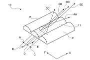
- FIG. 3 shows the outline of the optical characteristics of the lenticular lens 10 used as the first shield in the first embodiment.
- This lenticular lens 10 has a plurality of semi-cylindrical bodies 11 as optical elements arranged in a direction perpendicular to the longitudinal direction of the semi-cylindrical bodies 11 themselves (the X direction in FIG. 3 (the first direction orthogonal to the arrangement direction)). They are arranged continuously in the Y direction (second direction, arrangement direction).
- Each of the plurality of semi-cylindrical bodies 11 has a columnar shape with a semicircular cross section (not limited to a perfect circle, but also including a curved surface such as an ellipse whose radius of curvature changes). More specifically, the optical elements (semi-cylindrical bodies) 11 constituting the lenticular lens 10 are arranged side by side in the Y direction which intersects (perpendicularly in the illustrated example) the X direction assuming that the longitudinal direction thereof is the X direction. It is
- the lenticular lens 10 is arranged so that the first direction is horizontal (parallel to the horizontal line), the horizontal line is invisible and the vertical line appears to extend vertically, as shown in FIG. 4C.
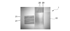
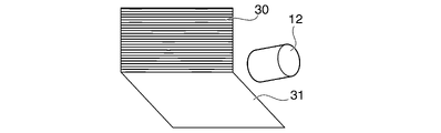
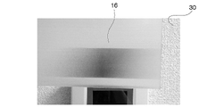
- FIG. 6A an image of a background 30 and a floor 31 connected thereto is acquired by an imaging unit 12 as an imaging device.
- the background 30 is, for example, a brick wall indicated by reference numeral 50 in FIG. 8A.
- image data with little change in the substantially horizontal direction is captured.
- this background 30 is represented by horizontal stripes.
- the floor 31 is, for example, a snow-covered white ground indicated by reference numeral 51 in FIG. 8A.
- this floor 31 is expressed as a white area surrounded by outlines.
- the image direction calculation unit 13 as the image processing device processes the image data captured by the imaging unit 12 .
- the image direction calculation unit 13 calculates a change in each direction within a plane including the image by, for example, differentiating the image data of the background 30 .
- the first panel direction determination unit 14 as the direction determination device determines a direction with an extremely small differential value, ie, an extremely small rate of change in image data, as a pseudo direction of the object 1 .
- the first panel direction determination unit 14 determines the horizontal direction in which the bricks are arranged in the brick wall 50 as the pseudo direction of the object 1 .
- the direction output unit 15 receives data on the pseudo direction determined by the first panel direction determination unit 14, and notifies the user of it by, for example, an image or sound.
- the output of direction output section 15 is the direction of the first panel.
- At least part of the concealment system shown in FIG. 5 may be a computer including a CPU and memory. That is, at least part of the functions of the concealment system may be realized by the CPU executing a program stored in memory.
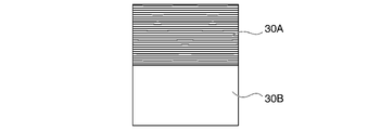
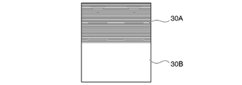
- the image data will have an image 30A with horizontal stripes at the top and an image 31A of the floor with a single color at the bottom, as shown in FIG. is obtained.
- the image direction calculation unit 13 calculates a value of "H (horizontal): 100%, V (vertical): 0%".
- the first panel direction determination unit 14 can determine that the background 30 has a shape that is continuous in the horizontal direction. Since the pseudo direction notified to the direction output unit 15 is horizontal, as shown in FIG. A panel 16 is placed in front of the object 1 .
- the first panel 16 is arranged with the first direction (X direction), which is the longitudinal direction of the lenticular lens, in the portrait orientation of FIG. 6B. That is, the first panel 16 is arranged so that the X direction of the lenticular lens 10 faces in a direction orthogonal to the horizontal direction, which is the pseudo direction determined by the first panel direction determination unit 14 .
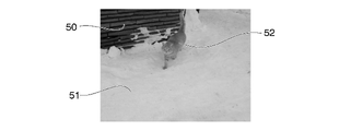
- FIG. 8A shows an image of the object (cat) 52 that was visible to the viewer when the first panel 16 was not installed.
- the image of the object (cat) 52 is such that its existence can be visually recognized when the first panel 16 is arranged so that the first direction is horizontal, as shown in FIG. 8B. looks like
- the image of the object (cat) 52 does not appear to be visible when the first panel 16 is oriented vertically in the first direction, as shown in FIG. 8C. That is, by directing the first direction of the first panel 16 in a direction orthogonal to the pseudo direction (horizontal direction in FIGS. 8A to 8C), the image of the brick wall 50, which is the background with a high proportion of horizontal components, can be obtained.
- the image of the object 52 can be concealed so as to blend in with the object 52, making it difficult for the viewer to visually recognize it.
- FIGS. 9A to 11D A configuration according to a second embodiment of the present disclosure embodying FIGS. 1 and 2 will be described with reference to FIGS. 9A to 11D.
- the same reference numerals are given to the same components as those in FIGS. 1 to 8C, and the description is simplified.
- an image of a background 30 and a floor 31 connected thereto is acquired by an imaging unit 12 as an imaging device.
- the imaging unit 12 may be a camera.
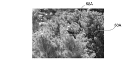
- the background 30 is, for example, a thicket of trees indicated by reference numeral 50A in FIG. 11A.
- this background 30 is represented by horizontal stripes. Also, in FIG.
- the area corresponding to the floor 31 does not exist. Also, the object is a bird indicated by reference numeral 52A in FIG. 11A.
- FIG. 9A when the background 30 is simple horizontal stripes, as shown in FIG. 10, image data is acquired in which the upper portion is an image 30A with horizontal stripes and the lower portion is an image 31A of a monochromatic floor surface. be done.
- the image data obtained by the imaging unit 12 is subjected to processing such as differentiation by the image direction calculation unit 13, and the direction determined by the first panel direction determination unit 14 is determined by the direction output unit 15.
- the user arranges the first panel 16 vertically and the second panel 17 horizontally according to the notified direction. That is, the user arranges the first panel 16 so that the first direction X is vertical, and arranges the first panel 16 so that the first direction X is horizontal and the second direction Y is vertical, according to the notified direction. 2 panels 17 are placed.
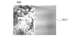
- the image of the scenery shown in FIG. 11A is viewed by the viewer as shown in FIG. 11B when only the first panel 16 is arranged.
- 11A is viewed by the viewer as shown in FIG. 11C when only the second panel 17 is arranged.
- the image of the bird 52A overlaps the image of the background 50A of trees, and as shown in FIG. 11D, it is almost invisible to the viewer.
- FIGS. 12A to 14 A configuration according to a third embodiment of the present disclosure embodying FIGS. 1 and 2 will be described with reference to FIGS. 12A to 14.
- FIG. 12A to 14 the same components as in FIGS. 1 to 11D are given the same reference numerals to simplify the description.
- This third embodiment is suitable for concealment when there is a large color difference between the background and the object.
- the imaging unit 12 acquires an image of the background 30 and the floor 31 connected thereto.
- the background 30 is, for example, a chromatic horizontally striped image having a predetermined ratio of R (red), G (green), and B (blue).
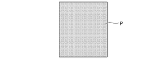
- the calculation result of the elements by the image processing device photographed by the photographing unit 12 is "H (horizontal): 100%, V (vertical): 0%, R: 214, G: 146, B77 (color code value)”.
- FIG. 13B shows a pixel P corresponding to “H (horizontal): 100%, V (vertical): 0%, R: 214, G: 146, B77” in images 30A and 31A of FIG. 13A.
- the photographing unit 12 sends the image data of the background 30 to the image direction calculating unit (image processing unit) 13 .
- the direction calculation unit 13 of this image calculates the change in the overall received light level in each of the horizontal and vertical directions, and calculates the average value of the received light level for each of the elements R, G, and B of each color.
- the first panel direction determination unit 14A determines the direction of the background from the values that serve as indicators of H and V changes. Also, the third panel color determination unit 14B determines the average color of the background.
- the output unit 15A outputs the direction and color to notify the user. In the example of FIG. 14, the output of the output unit 15A is the orientation of the first panel and the color of the panel that should be the third panel 18 .
- the average value (numerical value indicating the average color) per pixel is calculated by dividing the sum of the RGB components of all pixels included in the image data by the number of dots.
- a third panel 18 colored with that color (average value color) is placed between the object 1 and the first panel 16, as shown in FIG. 12B.
- the third panel 18 can hide the object 1 by existing inside the line segment connecting the contour of the first panel 16 and the object 1 as the vanishing point. Therefore, the planar shape of the third panel 18 may be smaller than that of the first panel 16 .
- a panel having a planar shape substantially identical to that of the object 1 may be arranged in close contact with the front surface of the object 1.
- the third panel 18 having a color close to the average value of the color of the background 30 in front of the object 1 in this way, an image in which the third panel 18 is integrated with the background 30 can be seen through the first panel 16 . observed by the viewer. As a result, a higher concealing effect can be obtained.
- FIGS. 15A to 24B A configuration according to a fourth embodiment of the present disclosure embodying FIGS. 1 and 2 will be described with reference to FIGS. 15A to 24B.
- 15A to 24B the same components as in FIGS. 1 to 14 are given the same reference numerals to simplify the description.
- so-called camouflaged third panels 18A to 18D as illustrated in FIGS. 17A to 17D are used in place of the monochromatic third panel 18 employed in the third embodiment.
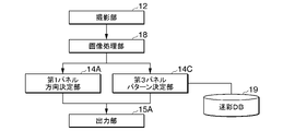
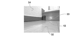
- an image of a background 30 and a floor 31 connected thereto is acquired by an image capturing unit (image capturing device) 12 .
- the background 30 and the floor 31 are, more specifically, the interior of a general house having a floor 32, a spandrel 33, and a wall 34, as shown in FIG. 19A.
- the imaging unit 12 sends the image data of the background 30 to the image direction calculation unit (image processing unit) 13 that calculates the direction of the image.
- the image direction calculator 13 calculates an overall change in the level of received light in each of the horizontal and vertical directions, and calculates the average value of the level of received light for each of the components R, G, and B of each color.
- the first panel direction determination unit 14A determines the pseudo direction of the background from the values that serve as indicators of H and V changes.
- the third panel pattern determination unit 14C determines the camouflage pattern (the third panel 18A illustrated in FIGS. Optimal camouflage is selected and determined from image data such as shape, hue, saturation, brightness, etc. that constitute camouflage of ⁇ 18D.
- the output unit 15A outputs a pseudo direction and a camouflage pattern to notify the user.
- the user Based on the camouflage pattern and the pseudo direction output from the output unit 15A, the user selects the third panel 18A in front of the object 1 in front of the background 30 and the first panel 18A in front of the object 1 in front of the background 30, as shown in FIG. 15B. A panel 16 is placed.
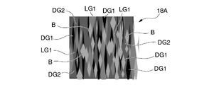
- FIG. 17A-17D show examples of camouflage patterns of third panels 18A-18D stored in camouflage DB 19.
- the camouflage pattern of the third panel 18A in FIG. 17A has a basic configuration in which a vertically long rhomboid square is used as a basic shape, and the aspect ratio or the absolute value of the length and width are combined in various ways.
- the camouflage pattern of the third panel 18A has vivid colors as a whole.
- the part indicated by symbol DG1 is the darkest dark green.
- the part indicated by symbol LG1 is the lightest light green. The green gradually fades from the point indicated by DG1, the point indicated by DG2, and the point indicated by LG1.
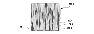
- the camouflage pattern of the third panel 18B in FIG. 17B is a monochrome image having a basic configuration in which the basic shape is a vertically long rhomboid square, and the aspect ratio or the absolute value of the length and width are combined in various ways. .
- the color gradually changes to gray, which is close to white, from the point indicated by the symbol BL1, which is the closest to black, to the point indicated by the symbol BL2, the point indicated by the symbol BL3, and the point indicated by the symbol BL4.
- 17C is a monochrome image having a basic configuration in which a vertically long rhomboidal square is used as a basic shape, and the aspect ratio or the absolute value of the vertical and horizontal lengths are combined in various ways. . From the point indicated by the code bl1, which is the closest to black, to the point indicated by the code bl2, the point indicated by the code bl3, and the point indicated by the code bl4, the color gradually changes to gray close to white.
- the camouflage pattern of the third panel 18B has a clear black-and-white contrast compared to the camouflage pattern of the third panel 18C.
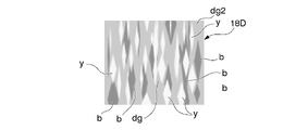
- the camouflage pattern of the third panel 18D generally has a pastel color tone (compared to the camouflage pattern of the third panel 18A).
- the part indicated by the symbol b is brown, the part indicated by the symbol dg is relatively dark green, and the part indicated by the symbol y is yellow.
- the average color composition of the camouflage patterns of the third panels 18A to 18D is indicated by color code as follows.
- the detected light level is lower because the camouflage pattern of the third panel 18A is darker than the camouflage pattern of the third panel 18D.
- the camouflage patterns of the third panels 18B and 18C are monochrome, the levels are equal between RGB.
- the camouflage pattern of the third panel 18B has a higher contrast and a darker black than the camouflage pattern of the third panel 18C, so the overall light level is low.
- a camouflage pattern (for example, the third panel 18D) with a small color average distance is selected and placed between the object 1B and the first panel 16.
- the painting of the camouflage pattern applied to the surface of the object 1B (or a sheet having a similar camouflage pattern applied to the surface and attached to the surface of the object) is the third panel. 18D.
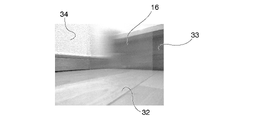
- the first panel 16 is arranged with the X direction (first direction) oriented vertically because the background is the spandrel wall 33 with a wide horizontal surface (horizontally oriented).
- the pseudo direction of the third panel 18 ⁇ /b>A is arranged along the X direction (first direction) of the first panel 16 .
- the camouflage pattern shown in FIG. 20 has a vertically long rhombus or a similar pastel color pattern.
- the location indicated by symbol B1 is dark blue
- the location indicated by symbol B2 is slightly light blue
- the location indicated by symbol P1 is dark pink
- the location indicated by symbol P2 is slightly light pink
- the location indicated by symbol Y is yellow. .
- FIG. 19A the object 1B, which is originally solid black, is arranged as a background 30 in the corner of the room. Furthermore, as shown in FIG. 19B, the surface of the object 1B is covered with the camouflage pattern shown in FIG. In this case, as shown in FIG. 19C, the object 1B can be hidden by the first panel 16 to such an extent that the boundary between the object 1B and the background 30 is difficult to distinguish.
- FIG. 21A is an image when only the first panel 16 is arranged with the first direction oriented vertically.
- FIG. 21B shows a first panel 16 using lenticular lenses oriented vertically in the first direction (X direction) and a second panel 17 (not shown) using lenticular lenses oriented horizontally in the first direction (X direction).
- FIG. 21C shows the case where the first panel 16 using a lenticular lens with the X direction (first direction) oriented vertically and the third panel 18A (or the third panels 18B, 18C, 18D) with camouflage are arranged.
- the third panel 18A or the third panels 18B, 18C, 18D
- camouflage camouflage
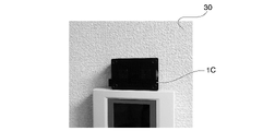
- FIG. 22A shows a fifth embodiment.
- the target object 1C of this fifth embodiment is a solid black pouch, as shown in FIG. 22A.
- FIG. 23A a third panel 18E is arranged in which monotone vertically long diamond-shaped figures are drawn in dark black BL1, slightly dark gray BL2, and light gray BL3.
- the image of the object 1C observed through the first panel 16 almost completely blends into the background 30, as shown in FIG. 23B.
- the third panel 18E is not limited to a panel placed between the object and the first panel 16, but may be a colored layer with camouflage applied directly to the surface of the object 1C as shown.
- Figures 24A and 24B show variations of the first panel with lenticular lenses used in the first to fifth embodiments. That is, the first panel 16C shown in FIG. 24A is curved like a cylindrical surface so as to surround the object 1. As shown in FIG. That is, the first panel 16C surrounds the object 1 and is curved such that the first direction is oriented perpendicular to the pseudo-direction of the background. Therefore, an effect of hiding the object 1 from viewers in various directions around the object 1 can be obtained.
- the first panel 16 is placed on the frame 22 with the first direction or the second direction oriented vertically, and a lifting device capable of moving in the vertical direction is mounted on both ends of the frame 22.
- a bolt 23 may be provided. That is, by adjusting the amount of downward projection of these two bolts 23, the first panel 16 can be tilted to a position other than horizontal, thereby providing the first level of stability against deviation from the pseudo-horizontal or vertical direction of the background. The tilt of the panel 16 can be adjusted so that the first direction or the second direction is exactly perpendicular to the pseudo-direction.
- an electric motor, a pneumatic device, or the like may be used to automatically adjust the inclination of the first panel 16.
- the present invention is not limited to such an example.
- the first panel 16 and the second panel 17 have the property of refracting light rays in a predetermined direction, such as a structure in which prisms are arranged, or a structure in which cylinder lenses having a cross section that forms a part of a cylindrical surface are arranged.
- a panel having another configuration in which optical elements are assembled may be adopted.
- the camouflage pattern other patterns may be adopted according to the brightness, color, size of the shape, etc. of the background.
- a method of changing the camouflage pattern there is a method of replacing the sheet that is directly attached to the object to be hidden, a method of replacing the panel placed on the floor, a method of rolling up the sheet with multiple types of camouflage patterns, and making one roll.
- a method of selectively arranging a necessary part in front of an object to be hidden by unwinding the film from the roll and winding it onto another roll may be adopted.
- the present disclosure can be used to conceal an object.
Landscapes
- Physics & Mathematics (AREA)
- General Physics & Mathematics (AREA)
- Optics & Photonics (AREA)
- Image Processing (AREA)
- Optical Elements Other Than Lenses (AREA)
- Studio Devices (AREA)
- Stereoscopic And Panoramic Photography (AREA)
Priority Applications (3)
| Application Number | Priority Date | Filing Date | Title |
|---|---|---|---|
| US18/273,180 US12504561B2 (en) | 2021-03-30 | 2022-03-08 | Concealment method and concealment system |
| JP2023510762A JP7537604B2 (ja) | 2021-03-30 | 2022-03-08 | 隠蔽方法および隠蔽システム |
| EP22779867.5A EP4249968A4 (en) | 2021-03-30 | 2022-03-08 | CONCEALMENT METHOD AND CONCEALMENT SYSTEM |
Applications Claiming Priority (2)
| Application Number | Priority Date | Filing Date | Title |
|---|---|---|---|
| JP2021056507 | 2021-03-30 | ||
| JP2021-056507 | 2021-03-30 |
Publications (1)
| Publication Number | Publication Date |
|---|---|
| WO2022209644A1 true WO2022209644A1 (ja) | 2022-10-06 |
Family
ID=83458866
Family Applications (1)
| Application Number | Title | Priority Date | Filing Date |
|---|---|---|---|
| PCT/JP2022/010121 Ceased WO2022209644A1 (ja) | 2021-03-30 | 2022-03-08 | 隠蔽方法および隠蔽システム |
Country Status (4)
| Country | Link |
|---|---|
| US (1) | US12504561B2 (https=) |
| EP (1) | EP4249968A4 (https=) |
| JP (1) | JP7537604B2 (https=) |
| WO (1) | WO2022209644A1 (https=) |
Citations (6)
| Publication number | Priority date | Publication date | Assignee | Title |
|---|---|---|---|---|
| JP2012061218A (ja) * | 2010-09-17 | 2012-03-29 | Tenyo Co Ltd | 物体出現トリック手品具 |
| JP3185126U (ja) | 2013-05-21 | 2013-08-01 | 株式会社スリーライク | 偏光シート |
| WO2015146167A1 (ja) | 2014-03-27 | 2015-10-01 | 富士フイルム株式会社 | 光学素子と光学素子を備えた拡張光学素子およびランプハウス |
| JP2015198400A (ja) * | 2014-04-02 | 2015-11-09 | 株式会社アイ・シー・テクノロジー | 物体透明化システム及び方法 |
| WO2020006621A1 (en) * | 2018-07-04 | 2020-01-09 | Hyperstealth Biotechnology Corporation | Interconnected lens materials arranged as lens sheets for improved camouflage |
| JP2021056507A (ja) | 2019-09-30 | 2021-04-08 | 三菱ケミカル株式会社 | 偏光膜製造用ポリビニルアルコール系樹脂フィルムおよび偏光膜 |
Family Cites Families (3)
| Publication number | Priority date | Publication date | Assignee | Title |
|---|---|---|---|---|
| US6623366B2 (en) * | 2001-02-28 | 2003-09-23 | Mark Setteducati | Magic trick with vanishing effect |
| US6912440B2 (en) * | 2003-04-04 | 2005-06-28 | Kurt Tooley | Camouflage covering and method of manufacture of the camouflage covering |
| US11974686B1 (en) * | 2021-12-28 | 2024-05-07 | Tyler Ruble | Device and method related to hiding delivered packages |
-
2022
- 2022-03-08 US US18/273,180 patent/US12504561B2/en active Active
- 2022-03-08 WO PCT/JP2022/010121 patent/WO2022209644A1/ja not_active Ceased
- 2022-03-08 JP JP2023510762A patent/JP7537604B2/ja active Active
- 2022-03-08 EP EP22779867.5A patent/EP4249968A4/en active Pending
Patent Citations (6)
| Publication number | Priority date | Publication date | Assignee | Title |
|---|---|---|---|---|
| JP2012061218A (ja) * | 2010-09-17 | 2012-03-29 | Tenyo Co Ltd | 物体出現トリック手品具 |
| JP3185126U (ja) | 2013-05-21 | 2013-08-01 | 株式会社スリーライク | 偏光シート |
| WO2015146167A1 (ja) | 2014-03-27 | 2015-10-01 | 富士フイルム株式会社 | 光学素子と光学素子を備えた拡張光学素子およびランプハウス |
| JP2015198400A (ja) * | 2014-04-02 | 2015-11-09 | 株式会社アイ・シー・テクノロジー | 物体透明化システム及び方法 |
| WO2020006621A1 (en) * | 2018-07-04 | 2020-01-09 | Hyperstealth Biotechnology Corporation | Interconnected lens materials arranged as lens sheets for improved camouflage |
| JP2021056507A (ja) | 2019-09-30 | 2021-04-08 | 三菱ケミカル株式会社 | 偏光膜製造用ポリビニルアルコール系樹脂フィルムおよび偏光膜 |
Non-Patent Citations (1)
| Title |
|---|
| See also references of EP4249968A4 |
Also Published As
| Publication number | Publication date |
|---|---|
| EP4249968A4 (en) | 2024-06-26 |
| JPWO2022209644A1 (https=) | 2022-10-06 |
| EP4249968A1 (en) | 2023-09-27 |
| US20240085593A1 (en) | 2024-03-14 |
| JP7537604B2 (ja) | 2024-08-21 |
| US12504561B2 (en) | 2025-12-23 |
Similar Documents
| Publication | Publication Date | Title |
|---|---|---|
| KR101994121B1 (ko) | 중간 뷰로부터의 효율적인 캔버스 뷰 생성 | |
| TWI489858B (zh) | 使用三維重建之影像捕捉 | |
| Nakamae et al. | A montage method: The overlaying of the computer generated images onto a background photograph | |
| US10950039B2 (en) | Image processing apparatus | |
| US8073318B2 (en) | Determining scene distance in digital camera images | |
| TWI253006B (en) | Image processing system, projector, information storage medium, and image processing method | |
| US20170345214A1 (en) | High Resolution (HR) Panorama Generation Without Ghosting Artifacts Using Multiple HR Images Mapped to a Low-Resolution 360-Degree Image | |
| US20160267710A1 (en) | Image Rendering Method and Apparatus | |
| US7529401B2 (en) | Image processing apparatus and image processing method | |
| EP2089852A1 (en) | Methods and systems for color correction of 3d images | |
| JP2009251141A (ja) | 立体画像表示装置 | |
| US20120243776A1 (en) | Image processing apparatus, image processing method, and program | |
| CN106454290B (zh) | 一种双摄像头图像处理系统及方法 | |
| CN111860632B (zh) | 多路图像一致性融合方法 | |
| CN110519585A (zh) | 一种应用于图像采集设备的成像校准方法及装置 | |
| US20040135739A1 (en) | Three-dimensional image display method, device for the same, light direction detector, and light direction detecting method | |
| CN108540790A (zh) | 一种用于移动终端的立体图像获取方法、装置及移动终端 | |
| WO2022209644A1 (ja) | 隠蔽方法および隠蔽システム | |
| KR101844843B1 (ko) | 플로팅 홀로그램 영상처리장치 및 그 방법 | |
| CN120070292A (zh) | 一种使用hdr全景图像进行光照环境空间明亮度评估的方法 | |
| CN108734666A (zh) | 一种鱼眼图像校正方法及装置 | |
| JP4046973B2 (ja) | 情報処理方法および画像混合装置 | |
| CN109300186B (zh) | 图像处理方法和装置、存储介质、电子设备 | |
| US20230177744A1 (en) | Augmented reality system and method for substrates, coated articles, insulating glass units, and/or the like | |
| JP5255522B2 (ja) | 表示・撮影装置 |
Legal Events
| Date | Code | Title | Description |
|---|---|---|---|
| 121 | Ep: the epo has been informed by wipo that ep was designated in this application |
Ref document number: 22779867 Country of ref document: EP Kind code of ref document: A1 |
|
| ENP | Entry into the national phase |
Ref document number: 2022779867 Country of ref document: EP Effective date: 20230622 |
|
| WWE | Wipo information: entry into national phase |
Ref document number: 18273180 Country of ref document: US |
|
| WWE | Wipo information: entry into national phase |
Ref document number: 2023510762 Country of ref document: JP |
|
| NENP | Non-entry into the national phase |
Ref country code: DE |