WO2022209494A1 - Straddling-type seat - Google Patents
Straddling-type seat Download PDFInfo
- Publication number
- WO2022209494A1 WO2022209494A1 PCT/JP2022/008024 JP2022008024W WO2022209494A1 WO 2022209494 A1 WO2022209494 A1 WO 2022209494A1 JP 2022008024 W JP2022008024 W JP 2022008024W WO 2022209494 A1 WO2022209494 A1 WO 2022209494A1
- Authority
- WO
- WIPO (PCT)
- Prior art keywords
- straddle
- seat
- type seat
- backrest
- lock
- Prior art date
Links
- 230000001681 protective effect Effects 0.000 claims description 23
- 230000003014 reinforcing effect Effects 0.000 claims description 5
- 238000005452 bending Methods 0.000 claims description 2
- 239000000463 material Substances 0.000 description 69
- 239000012530 fluid Substances 0.000 description 30
- 238000010438 heat treatment Methods 0.000 description 28
- 210000001217 buttock Anatomy 0.000 description 23
- 230000008602 contraction Effects 0.000 description 23
- 210000000689 upper leg Anatomy 0.000 description 21
- 238000011946 reduction process Methods 0.000 description 20
- 230000004048 modification Effects 0.000 description 17
- 238000012986 modification Methods 0.000 description 17
- 230000007246 mechanism Effects 0.000 description 14
- XLYOFNOQVPJJNP-UHFFFAOYSA-N water Substances O XLYOFNOQVPJJNP-UHFFFAOYSA-N 0.000 description 13
- 238000000034 method Methods 0.000 description 12
- 230000004308 accommodation Effects 0.000 description 11
- 238000007664 blowing Methods 0.000 description 11
- 238000003860 storage Methods 0.000 description 10
- 238000010586 diagram Methods 0.000 description 9
- 230000017531 blood circulation Effects 0.000 description 8
- 210000003205 muscle Anatomy 0.000 description 8
- 210000000078 claw Anatomy 0.000 description 7
- 230000002093 peripheral effect Effects 0.000 description 7
- 239000004519 grease Substances 0.000 description 6
- 238000004519 manufacturing process Methods 0.000 description 6
- 230000001976 improved effect Effects 0.000 description 5
- 238000003780 insertion Methods 0.000 description 5
- 230000037431 insertion Effects 0.000 description 5
- JOYRKODLDBILNP-UHFFFAOYSA-N Ethyl urethane Chemical compound CCOC(N)=O JOYRKODLDBILNP-UHFFFAOYSA-N 0.000 description 4
- 241000489861 Maximus Species 0.000 description 4
- 230000000694 effects Effects 0.000 description 3
- 210000001624 hip Anatomy 0.000 description 3
- 238000002347 injection Methods 0.000 description 3
- 239000007924 injection Substances 0.000 description 3
- 230000009467 reduction Effects 0.000 description 3
- 229920005989 resin Polymers 0.000 description 3
- 239000011347 resin Substances 0.000 description 3
- 238000009423 ventilation Methods 0.000 description 3
- 230000037237 body shape Effects 0.000 description 2
- 230000036760 body temperature Effects 0.000 description 2
- 238000005516 engineering process Methods 0.000 description 2
- 239000002828 fuel tank Substances 0.000 description 2
- 230000006870 function Effects 0.000 description 2
- 210000003127 knee Anatomy 0.000 description 2
- 230000008569 process Effects 0.000 description 2
- 238000012545 processing Methods 0.000 description 2
- 230000001737 promoting effect Effects 0.000 description 2
- 240000007594 Oryza sativa Species 0.000 description 1
- 235000007164 Oryza sativa Nutrition 0.000 description 1
- 239000004698 Polyethylene Substances 0.000 description 1
- 239000003086 colorant Substances 0.000 description 1
- 239000004020 conductor Substances 0.000 description 1
- 238000010276 construction Methods 0.000 description 1
- 238000013461 design Methods 0.000 description 1
- 238000001514 detection method Methods 0.000 description 1
- 230000002349 favourable effect Effects 0.000 description 1
- 230000005484 gravity Effects 0.000 description 1
- 210000004394 hip joint Anatomy 0.000 description 1
- 230000000149 penetrating effect Effects 0.000 description 1
- -1 polyethylene Polymers 0.000 description 1
- 229920000573 polyethylene Polymers 0.000 description 1
- 229920002635 polyurethane Polymers 0.000 description 1
- 239000004814 polyurethane Substances 0.000 description 1
- 238000003825 pressing Methods 0.000 description 1
- 235000009566 rice Nutrition 0.000 description 1
- 230000000638 stimulation Effects 0.000 description 1
- 230000008093 supporting effect Effects 0.000 description 1
- 229920003002 synthetic resin Polymers 0.000 description 1
- 239000000057 synthetic resin Substances 0.000 description 1
Images


Classifications
-
- B—PERFORMING OPERATIONS; TRANSPORTING
- B60—VEHICLES IN GENERAL
- B60N—SEATS SPECIALLY ADAPTED FOR VEHICLES; VEHICLE PASSENGER ACCOMMODATION NOT OTHERWISE PROVIDED FOR
- B60N2/00—Seats specially adapted for vehicles; Arrangement or mounting of seats in vehicles
- B60N2/90—Details or parts not otherwise provided for
- B60N2/914—Hydro-pneumatic adjustments of the shape
-
- B—PERFORMING OPERATIONS; TRANSPORTING
- B60—VEHICLES IN GENERAL
- B60N—SEATS SPECIALLY ADAPTED FOR VEHICLES; VEHICLE PASSENGER ACCOMMODATION NOT OTHERWISE PROVIDED FOR
- B60N2/00—Seats specially adapted for vehicles; Arrangement or mounting of seats in vehicles
- B60N2/56—Heating or ventilating devices
- B60N2/5678—Heating or ventilating devices characterised by electrical systems
- B60N2/5685—Resistance
-
- B—PERFORMING OPERATIONS; TRANSPORTING
- B62—LAND VEHICLES FOR TRAVELLING OTHERWISE THAN ON RAILS
- B62J—CYCLE SADDLES OR SEATS; AUXILIARY DEVICES OR ACCESSORIES SPECIALLY ADAPTED TO CYCLES AND NOT OTHERWISE PROVIDED FOR, e.g. ARTICLE CARRIERS OR CYCLE PROTECTORS
- B62J1/00—Saddles or other seats for cycles; Arrangement thereof; Component parts
- B62J1/10—Internal adjustment of saddles
-
- B—PERFORMING OPERATIONS; TRANSPORTING
- B62—LAND VEHICLES FOR TRAVELLING OTHERWISE THAN ON RAILS
- B62J—CYCLE SADDLES OR SEATS; AUXILIARY DEVICES OR ACCESSORIES SPECIALLY ADAPTED TO CYCLES AND NOT OTHERWISE PROVIDED FOR, e.g. ARTICLE CARRIERS OR CYCLE PROTECTORS
- B62J1/00—Saddles or other seats for cycles; Arrangement thereof; Component parts
- B62J1/12—Box-shaped seats; Bench-type seats, e.g. dual or twin seats
-
- B—PERFORMING OPERATIONS; TRANSPORTING
- B62—LAND VEHICLES FOR TRAVELLING OTHERWISE THAN ON RAILS
- B62J—CYCLE SADDLES OR SEATS; AUXILIARY DEVICES OR ACCESSORIES SPECIALLY ADAPTED TO CYCLES AND NOT OTHERWISE PROVIDED FOR, e.g. ARTICLE CARRIERS OR CYCLE PROTECTORS
- B62J1/00—Saddles or other seats for cycles; Arrangement thereof; Component parts
- B62J1/28—Other additional equipment, e.g. back-rests for children
Definitions
- the present invention relates to a straddle-type seat, and more particularly to a straddle-type seat with a backrest.
- a rear seat on which another passenger sits is formed one step higher behind a front seat on which the driver sits, and a stepped portion located at the boundary between the seats is a backrest on which the driver leans. is provided.
- a technique for changing the seating position of the driver by making the backrest movable and adjustable in the front-rear direction.
- Patent Document 1 by pulling a strap as an operating member attached to one end of a lock plate in a lateral unlocking direction, the fitting hole of the lock plate is disengaged from the fitting slit of the pipe frame. It is described that the backrest can be moved and adjusted in the front-rear direction.
- the present invention has been made in view of the above problems, and its object is to provide a straddle-type seat with a reduced number of parts while having a movable backrest.
- the straddle-type seat includes a backrest that is movable with respect to the seat body, and the backrest extends in the movement direction of the backrest.
- the seat body includes a bottom plate through which the adjusting member is inserted, a locking member that prevents movement of the backrest by coming into contact with the adjusting member, and a cover member that covers the locking member. , wherein the cover member completely covers the adjustment member.
- the cover member is formed with an extending portion extending in the moving direction of the adjusting member, and the extending portion extends in the vertical direction of the straddle-type seat to the adjusting portion. It is preferable that it overlaps with the member. With the above configuration, it is possible to appropriately cover the adjustment member, so that it is possible to prevent the grease from dripping downward and adhering to the vehicle body or the like.
- the lock member has an operation portion that is operated when moving the backrest, the operation portion protrudes outside the cover member, and the cover member:
- the operating portion is arranged in the recess and protrudes outward from an opening formed in the cover member, and the locking member is bent from the operating portion. and the bent portion is disposed so as to fill a gap between the operation portion and the opening when the straddle-type seat is viewed from below.
- the length of the portion where the bent portion and the cover member overlap in the vertical direction of the straddle-type seat is It is preferable that it is longer than the maximum amount of movement of the locking member.
- the operating portion has a bottom portion extending in the width direction of the straddle-type seat and a connection portion that connects the bottom portion and the bent portion, and the bent portion includes: It is preferable that it is shorter than the connecting portion. With the above configuration, it is possible to make the operation unit compact.
- the operation portion may include a side wall formed by bending from the bottom portion at a position facing the connecting portion in the width direction of the straddle-type seat.
- the bottom plate is formed with a through hole through which the adjustment member is inserted, and a protective member is provided in front of the through hole, and the protective member comprises the It is preferable that a protective portion through which the adjustment member is inserted is provided, and that the protective portion is formed longer on the upper side than on the lower side.
- a ring-shaped rib projecting inward is provided inside the protective portion, and the rib is in contact with the outer surface of the adjusting member.
- the lock member has an operation portion that is operated when the backrest is moved, and a plurality of the adjustment members are provided, and the operation portion includes a plurality of the adjustment members. a plurality of bolts provided so as to engage with each other, and reinforcing portions may be provided between the plurality of bolts.
- the operation portion is a bolt, the same number of bolts as the adjusting members are required, and the cover member has a plurality of bolt receiving holes. It can be reinforced to increase strength.
- the movable body has left and right third movable bodies disposed between the first movable body and the second movable body in the vertical direction of the seat back frame, and the third movable body has a plurality of expandable and contractible bags, and the plurality of bags are preferably stacked, have sizes different from each other, and are arranged in directions different from each other.
- the third movable body by supporting the seated person with the third movable body in addition to the first movable body and the second movable body, it is possible to enhance the supportability of the seated person.
- the lock member is covered with the cover member to improve the appearance, and the lock member is directly moved by the operating portion provided in the center portion in the width direction of the straddle-type seat. , it is possible to reduce the number of parts. Further, according to the straddle-type seat of the present invention, it is possible to arrange the operating portion in a compact manner. Further, according to the straddle-type seat of the present invention, it is possible to suppress the entry of foreign matter by filling the gap between the lock member and the cover member around the opening. Further, according to the straddle-type seat of the present invention, it is possible to prevent foreign matter from entering even when the lock member is slid to release the lock.
- the straddle-type seat of the present invention it is possible to make the operating portion compact. Further, according to the straddle-type seat of the present invention, when operating the operating portion, it is possible to grip the connecting portion and the side wall with fingers, thereby improving the operability. Further, according to the straddle-type seat of the present invention, the operator can intuitively understand the operation direction of the operation unit. In addition, according to the straddle-type seat of the present invention, when the backrest is moved, the adjustment member is prevented from getting wet due to water entering through the gap, and the upper side of the protection portion is lengthened so that the adjustment member is moved to the foremost position.
- the gap between the inner surface of the protective portion and the outer surface of the pipe frame can be properly closed, so that water cannot enter the seat body. Suppressed.
- the operation portion is a bolt
- the same number of bolts as the adjusting members are required. It is possible to increase the strength by reinforcing the weak portion between the holes.
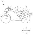
- FIG. 1 is an external view of a motorcycle provided with a motorcycle seat according to an embodiment of the present invention
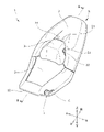
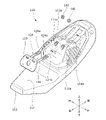
- FIG. 1 is an external view of a motorcycle seat according to an embodiment of the present invention
- FIG. It is a back view of a seat for motorcycles.
- It is an exploded perspective view of a lock mechanism.
- 4 is a perspective view of a lock plate and a lock cover;
- FIG. It is a bottom view of a lock plate and a lock cover.
- FIG. 11 shows a lock cover attached to the bottom plate;
- FIG. 4 is an enlarged view of a portion of the back surface of the bottom plate with the lock cover removed; It is a perspective view of a lock plate.
- FIG. 9 is a cross-sectional view taken along the line AA of FIG.
- FIG. 8 It is a schematic diagram which shows operation of a lock plate.
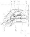
- FIG. 2 is a perspective view of the motorcycle seat with illustration of a cushion pad and an upholstery material omitted;
- FIG. 3 is a cross-sectional view taken along the line BB of FIG. 2;
- FIG. 3 is a view corresponding to the BB cross-sectional view of FIG. 2 showing an enlarged periphery of the protective member in a state where the backrest is arranged on the frontmost side;
- FIG. 5 is a schematic diagram illustrating a motorcycle seat according to a modification;
- FIG. 16 is a cross-sectional view taken along line CC of FIG. 15;
- FIG. 11 is a back view of a motorcycle seat according to a modification;
- FIG. 10 is a view showing a lock cover attached to a bottom plate of a motorcycle seat according to a modification;
- FIG. 5 is an external view of a motorcycle seat according to a second embodiment;
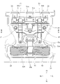
- 1 is an exploded perspective view of a motorcycle seat;
- FIG. FIG. 20 is a cross-sectional view taken along line AA of FIG. 19;
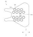
- FIG. 4 is a view of the front pad viewed from below, showing the arrangement of the air cells.
- FIG. 23 is a cross-sectional view taken along the line BB of FIG. 22;
- 3 is a block diagram showing the configuration of a fluid supply device and an air cell;
- FIG. 4 is an external view of a fluid supply device;
- FIG. FIG. 4 is a view of the front pad as seen from below, showing the layout of the planar heating elements.
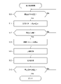
- FIG. 4 is a diagram showing the order in which air cells are inflated or deflated. It is a figure which shows the flow of a fatigue reduction process. It is a figure which shows the flow of the manufacturing procedure of a seat for motorcycles.
- FIG. 5 is an external view of a motorcycle seat according to a modification; It is a figure which shows the back side of the front pad and arrangement
- a motorcycle seat 1 as a straddle-type seat according to an embodiment of the present invention (hereinafter referred to as the present embodiment) will be described below with reference to FIGS. 1 to 18.
- FIG. The motorcycle seat 1 is a saddle type seat on which a person (passenger, driver) straddles.
- the motorcycle seat 1 is detachably attached to the vehicle body VB of the motorcycle V. In FIG. 2, the motorcycle seat 1 removed from the vehicle body VB will be described.
- each direction is defined as shown in FIGS.
- front-rear direction means the front-rear direction when viewed from a person sitting on the motorcycle seat 1 .
- the “seat width direction” corresponds to the left-right direction of the motorcycle seat 1 as seen from the seated person.
- vertical direction corresponds to the vertical direction when viewed from the person seated on the motorcycle seat 1 .
- a motorcycle seat 1 (hereinafter referred to as a motorcycle seat 1) according to the present embodiment is mounted on a motorcycle V by being attached to a vehicle body VB (motorcycle main body), as shown in FIG.
- the motorcycle seat 1 includes a seat body S and a backrest B as main components.
- FIG. 2 is an external view of the motorcycle seat 1, and for convenience of illustration, a part of the seat body S is shown in a state where the upholstery material T is removed and the cushion material C is exposed. Similarly, a portion of the backrest B is illustrated with the upholstery material 22 removed to expose the cushion material 21 .
- the seat body S includes a front seat portion 2 (front seat) on which the driver sits, and a rear seat portion 3 (rear seat) formed one step higher than the front seat portion 2 and on which other passengers sit.
- the motorcycle seat 1 is a two-seater seat having a front seating portion 2 at the front and a rear seating portion 3 at the rear.
- the front seat portion 2 and the rear seat portion 3 are portions on which the buttocks and thighs of the passenger of the motorcycle V (that is, the seated person) rest.
- the seat body S is constructed by placing a cushion material C on a bottom plate 10 to be described later and covering the surface of the cushion material C with a skin material T. As shown in FIG.
- Backrest B A backrest B against which the driver leans is provided in a step recess between the front seat portion 2 and the rear seat portion 3 .
- the backrest B is movable with respect to the seat body S, that is, it is configured to be manually adjustable in the longitudinal direction.
- the backrest B is configured by arranging a cushion material 21 on a backrest bottom 20 facing the stepped portion of the bottom plate 10, and covering the outer side of the cushion material 21 with a skin material 22.
- the skin material 22 is the back. It is fixed to the rest bottom 20 .
- the backrest B is shaped like a pillow with a concave front surface to cover the lower back of the driver.
- the lower surface of the backrest B is arranged on the rear upper surface of the front seating portion 2 so as to be movable in the front-rear direction.
- the upper surface of the backrest B is arranged so as to be continuous with the front upper surface of the rear seat portion 3 .
- a plate-like support frame 23 elongated in the left-right direction is fixed to the back surface of the backrest bottom 20 of the backrest B with a plurality of bolts and nuts (not shown).
- Front ends of a pair of pipe frames 24 as mounting frames for the backrest B are welded to the left and right sides of the support frame 23 .
- the pair of pipe frames 24 are parallel to each other, pass through an opening of the seat body S that opens to the bottom plate 10 and the upholstery material T, and are movably supported in the longitudinal direction by a locking mechanism R, which will be described later. It is As will be described later, the backrest B is fixed by the locking operation of the locking mechanism R, and can be manually moved and adjusted in the front-rear direction by releasing the lock.
- FIG. 3 shows a back view of the motorcycle seat 1.
- a bottom plate 10 as a bottom plate constituting the lower surface of the motorcycle seat 1 is made of a resin material.
- the bottom plate 10 has a front surface 11 and a back surface 12. Between the front surface 11 and the back surface 12 of the bottom plate 10 are formed a pair of through holes 11a through which a pair of pipe frames 24 (adjustment members) are respectively inserted. It is
- a housing recess 13 is formed in which a lock plate 31 of a lock mechanism R, a lock bracket 30, and the like, which will be described later, are housed.
- the accommodation recess 13 is a recess recessed in a direction (that is, upward) from the back surface 12 of the bottom plate 10 toward the front surface 11 .
- a lock cover 32 which will be described later, is attached with the lock mechanism R received in the housing recess 13. As shown in FIG.
- a bag housing portion 14 extending in the seat width direction is formed behind the housing recess 13 .
- a storage bag 50 which will be described later, is arranged in the bag storage portion 14 .
- the bag accommodating portion 14 is a concave portion that is recessed from the back surface 12 of the bottom plate 10 toward the front surface 11 (that is, upward).
- a front engaging portion 15a is formed in front of the bag accommodating portion 14, and a rear engaging portion 15b is formed at the rear end portion of the bag accommodating portion 14. As shown in FIG.
- the front locking portion 15a is a cut-and-raised portion formed to protrude forward, and the rear locking portion 15b is a cut-and-raised portion formed to protrude rearward.
- a plurality of engagement recesses 16 are formed in the front end portion of the housing recess 13, with which the engagement claws 32d of the lock cover 32 are fitted and engaged.
- the back surface 12 of the bottom plate 10 is provided with a striker 12a for attaching the motorcycle seat 1 to the vehicle body VB.
- the striker 12a can employ a known structure that engages with a striker engaging portion (not shown) provided on the vehicle body VB side.
- the lock mechanism R is integrally supported on the back surface 12 (lower surface) of the bottom plate 10, and includes a lock bracket 30, a lock plate 31 provided in the lock bracket 30 so as to be slidable in the left-right direction, the lock bracket 30 and A lock cover 32 covering the lock plate 31 is provided.
- the lock bracket 30 has a gate shape in cross section and extends in the seat width direction, and guide cylinders 34 are inserted into and fixed to insertion holes 30a and 30b opened in the front and rear walls of the left and right portions thereof. It is
- each guide tube 34 has an engaging piece 34a and an engaging piece 34b integrally protruding from the outer peripheral surface thereof, the engaging piece 34a and the engaging piece 34b engaging with the insertion hole 30a and the insertion hole 30b.
- a pair of pipe frames 24 connected to the backrest B are slidably passed through the pair of guide cylinders 34 .
- the adjustment member is a pipe frame 24 as a pillar.
- a plurality (three) of arc-shaped fitting slits 24a are formed on the outer surface of the intermediate portion of each pipe frame 24 at intervals in the axial direction.
- a through hole 34c selectively matching one of the plurality of fitting slits 24a is formed in the outer periphery of the front portion of each guide tube 34.
- a lock plate 31 is provided on the lock bracket 30 so as to be slidable in the left-right direction. there is The lock plate 31 can slide in the left-right direction (seat width direction) with respect to the lock bracket 30 within the length range of the long hole 31a.
- a pair of fitting holes 31b which can be selectively fitted through the passage opening 34c of the guide cylinder 34 are opened in one of the plurality of fitting slits 24a of the pipe frame 24 on the left and right sides of the lock plate 31. As shown in FIG.
- a lock spring 35 made of a coil spring is stretched between the lock bracket 30 (specifically, the spring engaging portion 30c) and the lock plate 31 (specifically, the spring engaging portion 31c).
- the lock spring 35 urges the lock plate 31 in the lock direction (the direction of the arrow a in FIG. 10, that is, the right direction) so that the fitting hole 31b of the lock plate 31 passes through the passage 34c and the plurality of fitting slits.
- the two pipe frames 24, ie the backrest B, can be locked by selectively engaging one of the 24a.
- the lock plate 31 is provided by integrally forming a lock release lever 31d as an operating portion at the lower end of a plate member extending mainly in the seat width direction.
- the lock release lever 31d includes a bottom portion 31e arranged at the lower end, a side wall 31f bent upward from the bottom portion 31e, and a connecting portion 31g.
- the side wall 31f and the connecting portion 31g face each other in the seat width direction, and the connecting portion 31g is formed longer than the side wall 31f in the vertical direction.
- the lock plate 31 has a bent portion 31h bent from the connecting portion 31g of the lock release lever 31d.
- the bent portion 31h is a plate portion extending outward in the seat width direction from the upper end of the connecting portion 31g.
- the unlocking lever 31d is connected to the projecting portion 31i of the plate member.
- the bottom portion 31e of the lock release lever 31d is connected to the lower end of the projecting portion 31i projecting downward from substantially the center of the plate member extending in the seat width direction and the vertical direction.
- the lock cover 32 (cover member) has a cover recess 32a recessed upward on its lower surface, and an opening 32b formed in the cover recess 32a.
- the opening 32b is arranged in the center of the lock cover 32 in the seat width direction. Both side portions of the cover recess 32a in the seat width direction protrude downward from the cover recess 32a, and the pair of guide tubes 34 and the pair of pipe frames 24 are accommodated.
- the lock cover 32 completely covers the pipe frame 24 so that the pipe frame 24 cannot be seen when the motorcycle seat 1 is viewed from below and from the side. More specifically, the lock cover 32 is formed with a pair of extending portions 32g that protrude and extend rearward in the moving direction of the pipe frame 24 (that is, the front-rear direction). The pair of extending portions 32g has a bulging shape protruding downward. The pair of extending portions 32g respectively overlap the pair of pipe frames 24 in the vertical direction. In other words, the pair of extending portions 32g are arranged to cover the pair of pipe frames 24 from below.
- the lock cover 32 By covering the lock mechanism R including the pipe frame 24 with the lock cover 32, particularly by completely covering the pipe frame 24 with the lock cover 32, the grease is prevented from dripping downward and adhering to the vehicle body or the like. becomes possible. Further, the presence of the lock cover 32 makes it possible to prevent the operator from touching the pipe frame 24 and the grease from adhering to the operator's hand.
- the pair of extending portions 32g overlap the pair of pipe frames 24 in the vertical direction, respectively, so that the pipe frames 24 can be appropriately covered. It is possible to prevent sticking.
- a lock release lever 31d protrudes downward and outward from an opening 32b formed in the lock cover 32. As shown in FIG.
- the lock release lever 31d protrudes outside the lock cover 32 and is provided at the center in the seat width direction.
- the central portion in the seat width direction is the region between the pair of pipe frames 24 in the seat width direction, in other words, the region between the pair of guide tubes 34 .
- a plurality of engaging claws 32d are formed to fit and engage with the engaging recess 16 (engaged portion) of the housing recess 13. As shown in FIG.
- the engaging claws 32d are hook-shaped claws protruding forward, and three engaging claws are formed side by side in the seat width direction.
- a pair of guide receiving portions 32e are formed on the back surface (upper surface) of the lock cover 32 to receive the pair of guide cylinders 34 therebetween.
- Each guide receiving portion 32e is a pair of protrusions that protrude upward from the rear surface of the lock cover 32. As shown in FIG.
- the opening 32b has a notch 32f on the front left side (more specifically, in the unlocking direction).
- the notch 32f has a depth that allows the lock plate 31 to be received when the lock plate 31 moves in the unlocking direction.
- the lock release lever 31d (that is, the lock plate 31) and the lock cover 32 (cover member), the lock release lever 31d (operating portion) can be easily recognized, which is preferable.
- the operator operates the unlocking lever 31d provided at the lower end of the lock plate 31 to move the lock plate 31 in the unlocking direction (arrow b direction in FIG. 11, that is, leftward). move to Specifically, when the operator moves the unlocking lever 31d in the unlocking direction, the lock plate 31 moves in the unlocking direction (arrow in FIG. 10) against the biasing force of the lock spring 35, as shown in FIG. b direction). At this time, the fitting hole 31b is disengaged from the fitting slit 24a of the pipe frame 24, and the backrest B can be moved and adjusted in the longitudinal direction (unlocked state).
- the lock plate 31 When the operator releases the pulling force on the unlocking lever 31d, the lock plate 31 is moved in the locking direction (direction of arrow a in FIG. 10) by the biasing force of the lock spring 35 as shown in FIG. , and the backrest B is fixed (locked state).
- the motorcycle seat 1 includes the backrest B that is movable with respect to the seat body S, and the backrest B is the backrest B. Equipped with a pipe frame 24 (adjusting member) extending in the movement direction (front-rear direction), the seat body S contacts the bottom plate 10 through which the pipe frame 24 is inserted, and the pipe frame 24 to move the backrest B. and a lock cover 32 (cover member) that covers the lock plate 31.
- the lock plate 31 is a lock release lever 31d that is operated when the backrest B is moved ( The lock release lever 31d protrudes outside the lock cover 32 and is provided at the center in the seat width direction.
- the lock release lever 31d protrudes outward from an opening 32b formed in the cover recess 32a of the lock cover 32 downward.
- the lock plate 31 is covered with the lock cover 32 from below to improve the appearance, and the lock release lever 31d provided at the center in the seat width direction directly moves the lock plate 31. , it is possible to reduce the number of parts.
- the lock cover 32 has a cover recess 32a recessed upward, and the lock release lever 31d is positioned inside the cover recess 32a in the seat front-back direction, the seat width direction, and the up-down direction.
- the lowermost portion of the unlocking lever 31d that is, the bottom portion 31e is positioned above the lowermost end of the region around the cover recess 32a of the lock cover 32 (FIG. 11).
- the bottom portion 31e is located above the base end portion (fixed end portion) of the engaging claw 32d of the lock cover 32 (FIG. 11).
- the lock release lever 31d has a side wall 31f bent from the bottom 31e at a position facing the connecting portion 31g in the seat width direction (Figs. 9 to 11). According to such a configuration, when operating the unlocking lever 31d, it is possible to pinch and grasp the connecting portion 31g and the side wall 31f with fingers from the seat width direction, thereby improving the operability at the time of unlocking.
- the lock release lever 31d protrudes downward and outward from an opening 32b formed in the lock cover 32, and the lock plate 31 has a bent portion 31h bent from the lock release lever 31d.
- the bent portion 31h is arranged so as to fill the gap between the lock release lever 31d and the opening 32b in a bottom view of the seat body S (that is, the motorcycle seat 1) (FIGS. 6 and 11). .
- the seat body S that is, the motorcycle seat 1
- the length L1 of the overlapping portion of the bent portion 31h and the lock cover 32 in the vertical direction is the length of the lock plate 31 (that is, the lock release lever 31d). It is longer than the maximum movement amount L2 (Fig. 11). According to such a configuration, even when the lock release lever 31d of the lock plate 31 is slid to release the lock (unlocked state), there is a gap between the lock plate 31 and the lock cover 32 around the opening 32b. Since it is possible to fill the gap between the two, entry of foreign matter is suppressed.
- the lock release lever 31d has a bottom portion 31e extending in the seat width direction and a connecting portion 31g connecting the bottom portion 31e and the bent portion 31h. shorter than the length of the connecting portion 31g in the direction (FIGS. 9-11). With such a configuration, it is possible to make the lock release lever 31d compact.
- protection member 40 As shown in FIGS. 12 to 14, a protective member 40 is provided in front of the pair of through holes 11a formed in the bottom plate 10. As shown in FIGS. The protection member 40 includes a ring-shaped peripheral edge portion 40a surrounding the outer periphery thereof, and a tubular protection portion 40b provided at the center portion. 13, illustration of the skin material T of the seat body S and the skin material 22 of the backrest B is omitted.
- the protection member 40 has a ring-shaped peripheral edge portion 40a around it, and guides water flowing forward from the rear seat portion 3 when it rains from above to below along the outer circumference of the peripheral edge portion 40a. It is possible. In addition, according to the peripheral portion 40a, it is possible to prevent water from entering the surroundings of the protective portion 40b. Since the peripheral edge portion 40a is inclined so that the lower end side is positioned more forward than the upper end side, the water flowing forward from the rear seat portion 3 when it rains is more appropriately guided downward from above. be done.
- the pipe frame 24 is inserted through the protective portion 40b.
- the cylindrical protective portion 40b is formed so that the upper side is longer than the lower side. According to such a configuration, when the backrest B is moved, it is possible to prevent the pipe frame 24 from getting wet due to water entering from the gap of the through hole 11a. In addition, by lengthening the upper side of the protective portion 40b, water is suppressed from entering the fitting portion between the pipe frame 24 and the lock plate 31 even when the pipe frame 24 is moved to the foremost portion (see FIG. 14). In the state shown, the frontmost fitting slit 24a is arranged inside the protective portion 40b).
- the protective portion 40b has two ring-shaped waterproof ribs 40c formed therein.
- the waterproof ribs 40c follow the movement of the pipe frame 24 even when the backrest B moves back and forth or a downward load is applied to the backrest B.
- the gap between the inner surface of the protective portion 40b and the outer surface of the pipe frame 24 is properly closed, so that water is prevented from entering the inside of the seat body S, that is, the back surface 12 side of the bottom plate 10. entry into the is inhibited.
- each waterproof rib 40c is arranged on the front side of the fitting slit 24a on the frontmost side. According to such a configuration, even when the backrest B (pipe frame 24) is moved to the foremost portion, entry of water through the fitting slit 24a of the pipe frame 24 is suppressed.
- the motorcycle seat 1 of this embodiment can accommodate articles such as tools on its back surface.
- the storage bag 50 is a bag that stores articles therein.
- the storage bag 50 is stored in the bag storage portion 14 which is a concave portion provided on the back surface 12 of the bottom plate 10 in a rolled state.
- a front engaging portion 15a as a hook is arranged between a pair of a plurality of pipe frames 24 (adjusting members), and a belt 51 is attached to the rear engaging portion 15b as a rear hook. It connects and supports the storage bag 50.
- the belt 51 has a front ring 51a at its front end and a rear ring 52a at its rear end.
- the front ring 51a is hooked on the front locking portion 15a
- the rear ring 51b is hooked on the rear locking portion 15b, so that the storage bag 50 is supported by the bag storage portion 14 by the belt 51. As shown in FIG.
- each element constituting the motorcycle seat 1 are not limited to the contents described in the above embodiment, and can be arbitrarily set without departing from the gist of the present invention. It is possible to design
- FIG. 15 is a schematic diagram for explaining a motorcycle seat according to a modification
- FIG. 16 is a sectional view taken along line CC of FIG. 15
- FIG. 17 is a rear view of the motorcycle seat according to the modification
- 18 is a view showing a lock cover 150 attached to a bottom plate 110 of a motorcycle seat according to a modification.
- a pair of through-holes 111a are formed through which the pair of adjusting members 124 are respectively inserted.
- a pair of nut attachment holes 111b to which nuts 140 are attached are provided behind the pair of through holes 111a.
- the front ends of a pair of adjustment members 124 as mounting frames for the backrest B are welded to the left and right sides of the support frame 123 of the backrest B.
- a pair of adjusting members 124 are parallel to each other, pass through a through hole 111a opened in the bottom plate 110, and are supported by a nut 140 and a bolt 141 as a locking mechanism (FIGS. 16 and 17).
- the pair of adjusting members 124 has a plate-like plate portion 124a extending in the front-rear direction.
- a plurality (three) of fitting holes 124b penetrating vertically are formed in the plate portion 124a (FIGS. 15 and 16).
- Two adjustment members 124 are provided, and two bolts 141 are also provided as operation parts.
- the plate portion 124a of the adjusting member 124 is released, and the backrest B can be freely moved in the front-rear direction (unlocked state).
- the operator inserts the bolt 141 into the corresponding fitting hole 124b and engages the nut 140 to fix the backrest B (locked state). ).
- the plate portion 124a is sandwiched in the sheet width direction by the sandwiching portion 112a provided on the back surface 112 of the bottom plate 110. As shown in FIG. According to such a configuration, the position in the seat width direction becomes stable when the backrest B is inserted through the through hole 111a.
- an accommodating recessed portion 113 for accommodating the plate portion 124a, the bolt 141, and the like is formed substantially in the center of the back surface 112 of the bottom plate 110 in the seat width direction.
- the accommodation recess 113 is a recess that is recessed in a direction from the back surface 112 of the bottom plate 110 toward the front surface 111 (that is, upward).
- the lock cover 150 is attached with the plate portion 124a and the bolt 141 (a part of the lock mechanism) received in the housing recess 113 .
- the lock cover 150 has ribs 151 as reinforcing parts between the pair of bolts 141 . If the operation portion is the bolts 141, the number of bolts 141 corresponding to the number of adjusting members 124 is also required, and the lock cover 150 has a plurality of receiving holes (not shown) for the bolts 141. The strength can be increased by reinforcing the fragile portion between the ribs 151 .
- FIG. 2 Description of the Related Art
- a straddle-type seat device for a motorcycle there has been proposed a device called an air cell containing a bag that can be inflated by compressing and injecting air therein.
- air flow is controlled so that a plurality of air cells accommodated in a cushion material in a seat are expanded or contracted according to the running state of the motorcycle.
- a technology has been proposed that controls the hardness of the seating surface by doing so, and maintains the seating position of the occupant in a good condition.
- FIG. 19 is an external view of the motorcycle seat 201.
- the motorcycle seat 201 is a two-seat seat having a front seating portion 202 for the rider in front and a rear seating portion 203 for a fellow passenger in the rear.
- the front seat portion 202 and the rear seat portion 203 are the portions with which the buttocks and thighs of the seated persons (that is, the driver and the passenger) of the motorcycle V come into contact.
- a non-seat portion 204 is provided on which the rider does not sit.
- the skin material 220 covers the cushion material 230 and has a seating surface 202A on which the seated person sits.
- the seating surface 202A has a buttock support surface 202Aa that supports the buttocks of the driver, and a thigh contact surface 202Ab that is sandwiched between the left and right thighs of the driver.
- a blower port 205 is provided at the rear of the front seating portion 202 for blowing gas blown by a blower 217 (air blower), which will be described later, toward the driver. More specifically, the air outlet 205 is provided at a lower portion (base end portion) of the non-seat portion 204 provided at the rear end of the front seat portion 202, facing the buttocks and hips of the driver.
- the driver can be cooled by blowing air from behind the buttocks and waist of the driver.
- the driver can feel a comfortable cool feeling due to the wind received from the front and the wind received from the rear while the vehicle is running.
- the air blown from the blower 217 hits the lower side of the buttocks of the seated person, it is possible to effectively suppress the dampness of the buttocks of the driver.
- the upholstery material 220 is provided with a mesh member at a position corresponding to the air outlet 205 of the motorcycle seat 201 .
- the mesh member has a mesh shape, and prevents foreign matter from entering the motorcycle seat 1 from the outside while ensuring ventilation of the blown air.
- FIG. 20 is an exploded perspective view of the motorcycle seat 201
- FIG. 21 is a cross-sectional view taken along line AA of FIG.
- the motorcycle seat 201 includes a bottom plate 210, a cushion material 230, and an upholstery material 220 (not shown).
- the motorcycle seat 201 is composed of a cushion material 230 placed on the bottom plate 210 and a skin material 220 covering the cushion material 230 and having a seating surface 202A.
- a bottom plate 210 that constitutes the lower surface of the motorcycle seat 201 and corresponds to a base material is made of a resin material. It has a ramp portion 212 corresponding to the portion 204 and a rear portion 213 corresponding to the rear seating portion 203 .
- the bottom plate 210 has a front surface 214 and a back surface 215, and the cushion material 230 is placed on the front surface 214.
- a blower 217 is attached to the back surface 215 (see FIG. 21). Blower 217 is connected to duct member 216 through blower opening 218 , and gas blown by blower 217 passes through duct member 216 .
- the opening 216a of the duct member 216 is arranged at a position corresponding to the blower port 205 described with reference to FIG.
- the cushion material 230 is a urethane pad that has elasticity and cushions the pressure applied to the seating surface 202A.
- the cushion material 230 is divided into two parts, a front pad 231 corresponding to the front seating portion 202 and a rear pad 232 corresponding to the non-seat portion 204 and the rear seating portion 203, in order from the front.
- the upper surface of the front pad 231 is covered with a planar heating element 233 . That is, a planar heating element 233 is arranged between the cushion material 230 (front pad 231) and the skin material 220, and can heat the driver's buttocks and thighs.
- the sheet heating element 233 will be described later with reference to FIG.
- the front pad 231 has, on its inner side, accommodation recesses 231a for accommodating a plurality of air cells 250, as will be described later with reference to FIGS.
- a rear end of the front pad 231 is formed with a pad slope portion 231b that slopes downward toward the rear in the seat width direction.
- the rear pad 232 has a notch 232a corresponding to the blower port 205. As shown in FIG. The notch 232a extends in the seat width direction, and by combining the rear pad 232 with the front pad 231, an opening corresponding to the air outlet 5 is formed. Also, the rear pad 232 has an opening 232b at an upper position corresponding to the intake port of the blower 217. As shown in FIG.
- FIG. 22 is a bottom view of the front pad 231 showing the arrangement of the air cells 250.
- FIG. 22 on the back side of the front pad 231 forming the front seating portion 202, 17 accommodating recesses 231a for accommodating the air cells 250 are formed in a predetermined regular arrangement.
- One air cell 250 is accommodated in each accommodation recess 231a.
- the accommodation recess 231a and the air cell 250 will be described in detail below.
- housing recesses 231a are regularly arranged at equal intervals. As shown in FIG. 22, five rows of accommodating recesses 231a are formed in the width direction. In the center row in the width direction, three housing recesses 231a are arranged so as to line up in the front-rear direction. In each row adjacent to the left and right of the center row, four housing recesses 231a are arranged in the front-rear direction. In each of the outermost rows in the width direction, three housing recesses 231a are arranged so as to line up in the front-rear direction.
- the front-rear positions of the three accommodation recesses 231a arranged in the center row in the width direction are equal to the front-rear positions of the four accommodation recesses 231a arranged in the laterally adjacent rows. They are alternately displaced so that only the distance differs.
- the three housing recesses 231a arranged in the outermost row in the width direction are also aligned in the front-rear direction with the four housing recesses 231a arranged in the adjacent row. They are alternately staggered so that they differ by equal distances.
- the air cell 250 is arranged in each housing recess 231a.
- the air cell 250 is a bag that is made of a stretchable material, such as a synthetic resin such as polyethylene or polyurethane, and can accommodate a fluid. That is, the air cell 250 expands when compressed air is injected, and contracts when the injected air is discharged.
- FIG. 23 is a cross-sectional view taken along the line BB of FIG. 22.
- the air cells 250 are accommodated from below in respective accommodating recesses 231a formed on the back side of the front pad 231.
- the upper wall surface of the housing recess 231 a is located below the upper end surface of the cushion material 230 . That is, a layer of urethane pad forming the front pad 231 is present above each accommodation recess 231a.
- the pressure (body pressure and seat pressure) applied to the seating surface 2A is buffered by the urethane pad.
- the air cell 250 expands, and as shown in FIG.
- the urethane pad cushions the pressing force received from below due to the expansion of the air cell 250, and presses and stimulates the buttocks and thighs of the seated person from the inside of the motorcycle seat 1.
- the seated person's gluteus maximus, biceps femoris, or adductor muscles are stimulated.
- the flow of compressed air is controlled so that the adjacent air cells 250 expand and contract (expand and contract) in a predetermined order.
- the so-called massage effect promotes the blood flow of the seated person, making it possible to reduce the fatigue of the seated person.
- a plurality of pressure sensors 251 associated with each air cell 250 are arranged at the upper end of each air cell 250 .
- the pressure sensor 251 can detect the pressure applied to the seating surface 202A at the position corresponding to each air cell 250. As shown in FIG. As will be described later, the pressure sensor 251 is used to determine whether or not the seated person is in contact with the motorcycle seat 1 at the position where the pressure sensor 251 is arranged.
- the pressure sensor 251 may be arranged between the upper surface of the front pad 231 and the skin material 220 instead of the upper end of the air cell 250 . Thereby, the pressure applied to the seating surface 202A can be detected more accurately.
- the 17 air cells 250 accommodated in the front pad 231 include a group of 7 right air cells 250A arranged on the right side as seen from the seated person, and It includes seven left air cell groups 250B arranged on the left side as viewed.
- the right air cell group 250A and the left air cell group 250B are arranged symmetrically with respect to the widthwise center of the motorcycle seat 1 as a central axis.
- the right air cell group 250A presses and stimulates the right buttocks and right thigh of the seated person, while the left air cell group 250B presses the left buttocks and left thigh of the seated person. to inspire. As a result, the fatigue of both the right and left lower bodies of the seated person can be reduced.
- FIG. 24 is a block diagram showing the configuration of the fluid supply device 240 and the air cell 250 incorporated in the motorcycle seat 1.
- the fluid supply device 240 includes an air supply pump 241 that generates compressed air, a valve unit 242, and an ECU (Electric Control Unit) 244 that controls the entire fluid supply device 240 as main components. That is, the ECU 244 (control unit) controls the flow of compressed air via the air supply pump 241 and the valve unit 242, and executes fatigue reduction processing, which will be described later.
- the fluid supply device 240 also includes a tube 243 that supplies compressed air from the air supply pump 241 to the air cell 250 via the valve unit 242 .
- FIG. 25 is an external view of the fluid supply device 240.
- the air supply pump 241 is composed of a small air pump that generates compressed air.
- the valve unit 242 has a plurality of compressed air outlets, and can switch the supply destination of the compressed air generated by the air supply pump 241 .
- the valve unit 242 has an electromagnetic valve (not shown) inside, and by controlling the electromagnetic valve, it is possible to select a discharge port from which compressed air is actually discharged out of a plurality of discharge ports. switch.
- a tube 243 is connected to each outlet. Each tube 243 forms a compressed air supply path. Each tube 243 is connected to a compressed air inlet of the air cell 250 . Therefore, when the outlet from which the compressed air is actually discharged in the valve unit 242 is switched, the supply destination of the compressed air (that is, the air cell 250 to which the compressed air is sent) is switched. One or two air cells 250 are connected to the tip of each tube 243 .
- the ECU 244 has a function of performing ventilation control of the blower 217 and heating control of the planar heating element 233 , in addition to the fluid supply device 240 . That is, the ECU 244 performs heating control of the planar heating element 233 based on the outside air temperature measured by the temperature sensor 245 .
- the temperature sensor 245 is composed of a thermistor or a resistance temperature detector, and is attached inside the skin material 220 to measure the outside air temperature.
- the temperature sensor 245 is positioned away from the seating surface 202A, for example, at the front end or rear end of the motorcycle seat 201, in order to accurately measure the outside air temperature without being affected by the body temperature of the seated person. attached to the
- the ECU 244 controls the heating of the planar heating element 233 when the outside air temperature is lower than a predetermined temperature.
- a comfortable driving environment is provided to the seated person, and blood flow to the buttocks and thighs of the seated person is promoted. A seated person's fatigue can be reduced.
- FIG. 26 is a bottom view of the front pad 231 and shows the arrangement of the air cells 250 and the planar heating element 233.
- the planar heating element 233 is composed of a conductive wire (resistive heating element) that is connected to a pair of electrodes and meanders while changing its orientation in the left-right direction, covering the entire seating surface 202A in a planar shape. It is That is, the planar heating element 233 is arranged between the skin material 220 and the cushion material 230 to heat the inside of the buttocks and thighs of the seated person. As a result, blood flow in the buttocks and thighs of the seated person can be promoted, and fatigue of the seated person can be reduced.
- the conductor pattern and electrode arrangement of the planar heating element 233 are not limited to the example shown in FIG.
- a pair of electrode lines (bus bars) extending in the front-rear direction may be arranged at both ends of the cushion material 230 in the width direction, and conductive wires having a grid pattern may be arranged in a plane between the electrodes.
- the seating surface 202A can be heated evenly and evenly, and even if a wire breakage occurs in a part of the wire pattern, the seated person can be heated by the conductive wire at a location different from the wire breakage location.
- the durability of the planar heating element 233 can be enhanced.
- the ECU 244 injects compressed air into the air cells 250 to stimulate the seater's gluteus maximus, biceps femoris, and adductor muscles to promote blood flow in the seater's buttocks and thighs. to control the flow of Specifically, the ECU 244 controls the flow of compressed air so that the air cells 250 adjacent to each other expand or contract in a predetermined order.
- the air cells 250 include the right air cell group 250A and the left air cell group 250B, and the right air cell group 250A and the left air cell group 250B are arranged symmetrically with respect to the center in the width direction. there is The position and order of expansion and contraction of the air cells 250 will be described below for the right air cell group 250A, but the same applies to the left air cell group 250B.
- FIG. 27 is a diagram showing an expansion/contraction pattern.
- the air cell 250 (hereinafter referred to as the air cell 250A1) disposed on the rearmost side in the row near the center in the width direction, that is, the rear of the seated person.
- the air cells 250A1 arranged at positions corresponding to the lower rear are inflated first.
- the air cell 250A1 is contracted, and the air cell 250 (referred to as the air cell 50A2) arranged second from the rear side in the row near the center, that is, is arranged at a position corresponding to the lower front of the seated person's buttocks.
- the air cell 250A2 that has been inflated second.
- the air cell 250A2 is contracted, and the air cell 250 (referred to as 250A3) arranged third from the rear side (second from the front side) in the row near the center, that is, the back side of the thigh of the seated person
- the air cell 250A3 arranged at a position corresponding to the hip joint side of the third inflates.
- the air cell 250A3 is contracted, and the frontmost air cell 250 (referred to as air cell 250A4) in the row on the outer side in the width direction, i.e., the position corresponding to the inner thigh of the seated person.
- the air cell 250A4 is inflated.
- the following 5th, 6th, 7th and 8th control the air cells 250 in the opposite order from the 1st to 4th. That is, the air cell 250A4 contracts from the expanded state, and the air cell 250A3 expands. Subsequently, air cell 250A3 contracts and air cell 250A2 expands. Then, the air cell 250A2 contracts and the air cell 250A1 expands. Finally, the air cell 250A1 is deflated, and the series of inflation/deflation control of the inflation/deflation pattern shown in FIG. 27 is completed.
- the ECU 244 repeats the expansion/contraction pattern described above at predetermined time intervals.
- the gluteus maximus, biceps femoris, and adductor muscles of the seated person are stimulated from the inside of the motorcycle seat 1 .
- the so-called massage effect promotes blood flow in the buttocks and thighs of the seated person, thereby reducing fatigue of the seated person.
- the expansion/contraction pattern of the air cell 250 controlled by the ECU 244 is not limited to that shown in FIG.
- a memory 244a (see FIG. 24) incorporated in the ECU 244 can store a plurality of operation modes, and can store a different expansion/contraction pattern in association with each operation mode.
- FIG. 28 shows the flow of fatigue reduction processing executed by the ECU 244 .
- the ECU 244 first determines whether or not the conditions for starting the fatigue reduction process are satisfied (step S10).
- the condition for starting the fatigue reduction process is, for example, that the motorcycle V has started running.
- a predetermined time for example, one hour
- the fact that there is an operation input for starting the fatigue reduction process by the driver may be regarded as a condition for starting the fatigue reduction process. It may be used as a condition for starting the reduction process.
- the biometric information of the seated person may be detected based on the detection result of the pressure sensor 251 described above, the fatigue of the seated person may be estimated based on the biometric information, and this may be used as the starting condition for the fatigue reduction process. If it is determined that the conditions for starting the fatigue reduction process are not satisfied (step S10: No), the process waits until the conditions for starting the fatigue reduction process are satisfied.
- the ECU 244 reads the expansion/contraction pattern from the memory 244a (step S11).
- the expansion/contraction pattern is, as described above, information that can specify the positions and order of the air cells 250 that expand or contract.
- the expansion/contraction pattern may include information that can specify the timing of expansion or contraction in addition to the position and order.
- the expansion/contraction pattern may also include information that can specify the expansion/contraction amount and the contraction amount.
- the memory 244a stores a plurality of inflation/deflation patterns in advance, and the driver can select a desired inflation/deflation pattern and read it from the memory 244a.
- the ECU 244 determines whether or not it is necessary to correct the expansion/contraction pattern read in step S11 (step S12). Specifically, the ECU 244 determines, based on the pressure signal detected by the pressure sensor 251, whether or not the body pressure and seat pressure of the seated person are detected for the air cells 250 stored in the inflation/deflation pattern. Thereby, it is determined whether or not there is an air cell 250 corresponding to a position where the seated person is not in contact with the motorcycle seat 201 among the air cells 250 stored in the inflation/deflation pattern.
- step S12 When it is determined that the expansion/contraction pattern needs to be corrected (step S12: Yes), the ECU 244 corrects the expansion/contraction pattern (step S13).
- the air cell 250 located at a position where the seated person does not come into contact with the motorcycle seat 201 is excluded from the target of the inflation/deflation control.
- the ECU 244 controls only the air cell 250 corresponding to the pressure sensor 251 that detects the pressure applied to the seating surface 202A.
- only the air cells 250 that need to be deflated can be properly inflated and deflated according to the body shape of the seated person.
- step S12 If it is determined that the expansion/contraction pattern does not need to be corrected (step S12: No), or if the expansion/contraction pattern is corrected in step S13, the heating of the planar heating element 233 is controlled (step S14), and the air cell 250 is expanded and contracted (step S15). Since the inflation/deflation control of the air cell 250 has been described with reference to FIG. 27, detailed description thereof will be omitted.
- the ECU 244 determines whether or not the conditions for stopping the fatigue reduction process are satisfied (step S16).
- the condition for stopping the fatigue reduction process is, for example, when the seated person leaves the motorcycle seat 201 .
- the ECU 244 determines that the seated person has left the motorcycle seat 201 on the condition that none of the pressure sensors 251 detect body pressure or seat pressure.
- the condition for stopping the fatigue reduction process may be that the motorcycle V has stopped running. Then, the fact that there is an operation input for stopping the fatigue reduction process by the driver may be set as the condition for stopping the fatigue reduction process.
- step S16: No When it is determined that the conditions for stopping the fatigue reduction process are not satisfied (step S16: No), the ECU 244 returns to step S15 to continue the fatigue reduction process. On the other hand, when it is determined that the condition for stopping the fatigue reduction process is satisfied (step S16: Yes), the ECU 244 ends the fatigue reduction process.
- FIG. 29 is a diagram showing the flow of the manufacturing procedure of the motorcycle seat 201.
- the air cell 250 is arranged on the back side of the front pad 231 that constitutes the cushion material 230 . That is, one air cell 250 capable of accommodating compressed air is accommodated in each of the 17 accommodating recesses 231a formed on the back side of the front pad 231 (bag disposing step) (step S20).
- the cushion material 230 is attached to the bottom plate 210 (cushion material attachment process) (step S21). That is, the front pad 231 and the rear pad 232 containing the air cells 250 are attached to the bottom plate 10 in step S20.
- the planar heating element 233 is arranged on the upper surface of the cushion material 230 .
- the fluid supply device 240 is arranged on the bottom plate 210 (control section arrangement step) (step S22).
- the fluid supply device 240 may be fixed to the back surface 15 of the bottom plate 210 or may be fixed to the front surface 214 of the bottom plate 210 (between the bottom plate 210 and the cushion material 230).
- the fluid supply device 240 has an ECU 244 that controls the flow of compressed air so that the plurality of adjacent air cells 250 expand in a predetermined order.
- the cushion material 230 placed on the bottom plate 210 is covered with the skin material 220 (skin material covering step) (step S23).
- FIG. 30 The air blowing function according to the first modification will be described with reference to FIGS. 30 and 31.
- FIG. In the above-described embodiment, the gas blown by the blower 217 is sent toward the seated person from the air blowing port 305 provided behind the seating surface 202A, thereby suppressing an increase in body temperature of the surface of the buttocks and waist of the seated person. rice field.
- the gas blown by the blower 317 is sent toward the seated person from the air blowing port 305 provided in the central portion in the width direction of the seating surface 302A.
- FIG. 31 is a diagram showing the arrangement of the rear side of the front pad 331 and the air cell 350 according to the first modified example.
- 14 housing recesses 331a for housing the air cells 350 are formed on the back side of the front pad 331, 14 housing recesses 331a for housing the air cells 350 are formed.
- the housing recess 331a is composed of a housing recess 331a for housing the right air cell group 350A and a housing recess 331a for housing the left air cell group 350B.
- a vent hole 331 c is formed in the central portion of the front pad 331 to guide the gas blown by the blower 317 to the blow port 305 .
- the gas blown by the blower 317 is guided to the ventilation hole 331c and directed to the air blowing port 305A provided in the central portion in the width direction of the seating surface 302A. Then, the gas that has passed through the blower port 305A is sent out from below the seat toward the seated person. As a result, the bottom of the seated person's buttocks is cooled, and it becomes possible to effectively suppress the dampness of the seated person's buttocks.
- the expansion/contraction pattern according to the second modification controls the flow of compressed air so that the air cell 350 arranged at the position corresponding to the adductor muscle of the seated person expands/contracts.
- the flow of compressed air is controlled such that the air cell 350 arranged at a position corresponding to the thigh contact surface 302Ab in the seating surface 302A expands and contracts.
- the heating is controlled by the planar heating element 233 provided on the upper surface of the front pad 231, but the present invention is not limited to this.
- compressed air injected into the air cell 350 may be heated, and the air cell 350 may heat and control the seating surface 302A.
- the fluid supply device 340 may incorporate a heater to heat the compressed air.
- the fluid supply device 340 is described as built in the motorcycle seat 301 .
- the fluid supply device 340 may be arranged outside the motorcycle seat 301 and on the vehicle body VB (motorcycle main body).
- the fluid supply device 240 provided on the vehicle body VB controls the flow of compressed air injected into the air cell 350 provided inside the motorcycle seat 201, the present invention can be applied. shall be included.
- the straddle-type seat according to the present embodiment has been described as an example of a vehicle seat that is mainly used for a two-wheeled vehicle.
- the straddle-type seat according to the present embodiment is not limited to a vehicle seat for a two-wheeled vehicle, and can be applied to, for example, a snowmobile, a personal watercraft, a three-wheeled buggy, or a construction machine seat.
- the straddle-type seat of the present invention it is possible to reduce the fatigue of the seated person by promoting the blood flow of the seated person.
- the following notes are further disclosed with respect to the embodiments described with reference to FIGS. 19-31.
- Appendix 1 In a straddle-type seat having a seating surface on which a seated person sits, a plurality of bags disposed inside the seating surface and capable of containing a fluid; and a control unit that controls the flow of the fluid, The straddle-type seat, wherein the control unit controls the flow of the fluid so that the plurality of bags positioned adjacent to each other expand and contract in a predetermined order.
- the plurality of bag bodies include a plurality of right side bag bodies arranged on the right side in the lateral direction of the seat and a plurality of left side bag bodies arranged on the left side inside the seating surface.
- the straddle-type seat according to Supplementary Note 1 characterized by: (Appendix 3) a plurality of pressure sensors that detect pressure applied to the seating surface and are associated with each of the plurality of bags; The straddle according to Supplementary Note 1, wherein the control unit controls the flow of the fluid so as to expand and contract the bag corresponding to the pressure sensor that detects the pressure applied to the seating surface.
- formula sheet. (Appendix 4) a cushioning material; a skin material covering the cushion material and having the seating surface, The straddle-type seat according to appendix 1, wherein a heating element is arranged between the cushion material and the skin material.
- (Appendix 5) a blower;
- (Appendix 6) a blower;
- a method for controlling fluid in a straddle-type seat having a seating surface on which a seated person sits comprising: The straddle-type seat includes a plurality of bags disposed inside the seating surface and capable of containing a fluid; and a control unit that controls the flow of the fluid, A fluid control method in a straddle-type seat, wherein the control unit controls the flow of the fluid so that the plurality of bags positioned adjacent to each other expand and contract in a predetermined order.
Landscapes
- Engineering & Computer Science (AREA)
- Mechanical Engineering (AREA)
- Aviation & Aerospace Engineering (AREA)
- Transportation (AREA)
- Seats For Vehicles (AREA)
Abstract
The purpose of the present invention is to provide a straddling-type seat that comprises a movable backrest and has a reduced number of components. A straddling-type seat (S) comprising a backrest (B) that is movable relative to a seat body (S), wherein the backrest (B) comprises a pipe frame (24) that extends in the direction of movement of the backrest (B), the seat body (S) comprises a bottom plate (10) through which the pipe frame (24) is inserted, a lock plate (31) that prevents movement of the backrest (B) by contacting the pipe frame (24), and a lock cover (32) that covers the lock plate (31), and the lock cover (32) completely covers the pipe frame (24).
Description
本発明は、跨座式シートに係り、特にバックレストを備える跨座式シートに関する。
The present invention relates to a straddle-type seat, and more particularly to a straddle-type seat with a backrest.
自動二輪車用シートにおいて、運転者の着座する前部シートの後方に他の乗員の着座する後部シートが一段高く形成され、それらのシートの境界に位置する段部に、運転者の凭れ掛かるバックレストを設けたものがある。そのような自動二輪車用シートにおいて、バックレストを前後方向に移動調節可能として運転者の着座位置を変更する技術が知られている。
In a motorcycle seat, a rear seat on which another passenger sits is formed one step higher behind a front seat on which the driver sits, and a stepped portion located at the boundary between the seats is a backrest on which the driver leans. is provided. In such a motorcycle seat, there is known a technique for changing the seating position of the driver by making the backrest movable and adjustable in the front-rear direction.
特許文献1には、ロックプレートの一端に結着された操作部材としてのストラップを側方のロック解除方向に牽引することで、ロックプレートの嵌合孔がパイプフレームの嵌合スリットから外れて、バックレストが前後方向に移動調整が可能になることが記載されている。
In Patent Document 1, by pulling a strap as an operating member attached to one end of a lock plate in a lateral unlocking direction, the fitting hole of the lock plate is disengaged from the fitting slit of the pipe frame. It is described that the backrest can be moved and adjusted in the front-rear direction.
特許文献1に記載されている技術では、ロックプレートにストラップを取り付けており、部品点数が多くなっていた。
In the technology described in Patent Document 1, the strap is attached to the lock plate, increasing the number of parts.
本発明は、上記の課題に鑑みてなされたものであり、その目的は、移動可能なバックレストを備えつつ部品点数が削減された跨座式シートを提供することにある。
The present invention has been made in view of the above problems, and its object is to provide a straddle-type seat with a reduced number of parts while having a movable backrest.
前記課題は、本発明の跨座式シートによれば、シート本体に対して移動可能なバックレストを備えた跨座式シートであって、前記バックレストは、前記バックレストの移動方向に延在する調節部材を備え、前記シート本体は、前記調節部材が挿通されるボトムプレートと、前記調節部材に当接することで前記バックレストの移動を阻止するロック部材と、前記ロック部材を覆うカバー部材と、を備え、前記カバー部材は、前記調節部材を完全に覆っていること、により解決される。
According to the straddle-type seat of the present invention, the straddle-type seat includes a backrest that is movable with respect to the seat body, and the backrest extends in the movement direction of the backrest. The seat body includes a bottom plate through which the adjusting member is inserted, a locking member that prevents movement of the backrest by coming into contact with the adjusting member, and a cover member that covers the locking member. , wherein the cover member completely covers the adjustment member.
上記のように構成された本発明の跨座式シートでは、調節部材の表面には、調節部材を滑らかに摺動させるためにグリスが塗布されているが、カバー部材で調整部材を完全に覆うことで、グリスが下方へと垂れて車体などに付着してしまうことを防ぐことが可能となる。
In the straddle-type seat of the present invention constructed as described above, grease is applied to the surface of the adjusting member so that the adjusting member slides smoothly, but the covering member completely covers the adjusting member. As a result, it is possible to prevent the grease from dripping downward and adhering to the vehicle body or the like.
上記の跨座式シートにおいて、前記カバー部材には、前記調節部材の移動方向に延在する延出部が形成されており、前記跨座式シートの上下方向において、前記延出部は前記調節部材と重なっているとよい。
上記の構成では、適切に調整部材を覆うことが可能となるため、グリスが下方へと垂れて車体などに付着してしまうことを防ぐことが可能となる。 In the above-described straddle-type seat, the cover member is formed with an extending portion extending in the moving direction of the adjusting member, and the extending portion extends in the vertical direction of the straddle-type seat to the adjusting portion. It is preferable that it overlaps with the member.
With the above configuration, it is possible to appropriately cover the adjustment member, so that it is possible to prevent the grease from dripping downward and adhering to the vehicle body or the like.
上記の跨座式シートにおいて、前記ロック部材は、前記バックレストを移動させる際に操作される操作部を有し、前記操作部は、前記カバー部材の外側に突出しており、前記カバー部材は、上方に向かって窪んだ凹部を有し、前記操作部は、前記凹部に配置されており、前記カバー部材に形成された開口部から外側に突出しており、前記ロック部材は、前記操作部から折り曲げられた折曲部を有し、前記折曲部は、前記跨座式シートの下面視において前記操作部と前記開口部との間の隙間を埋めるように配置されているとよい。
上記の構成では、開口部の周囲におけるロック部材とカバー部材の間の隙間を埋めることで異物が入ることを抑制することが可能となる。 In the above-described straddle-type seat, the lock member has an operation portion that is operated when moving the backrest, the operation portion protrudes outside the cover member, and the cover member: The operating portion is arranged in the recess and protrudes outward from an opening formed in the cover member, and the locking member is bent from the operating portion. and the bent portion is disposed so as to fill a gap between the operation portion and the opening when the straddle-type seat is viewed from below.
In the above configuration, it is possible to prevent foreign matter from entering by filling the gap between the lock member and the cover member around the opening.
上記の跨座式シートにおいて、前記バックレストの移動が阻止されているロック状態において、前記折曲部と前記カバー部材が前記跨座式シートの上下方向で重なっている部分の長さは、前記ロック部材の最大移動量よりも長いとよい。
上記の構成では、ロックを解除するためにロック部材をスライドさせた状態においても異物が入ることを抑制することが可能となる。 In the above-described straddle-type seat, in a locked state in which movement of the backrest is blocked, the length of the portion where the bent portion and the cover member overlap in the vertical direction of the straddle-type seat is It is preferable that it is longer than the maximum amount of movement of the locking member.
With the above configuration, it is possible to prevent foreign matter from entering even when the lock member is slid to unlock.
上記の跨座式シートにおいて、前記操作部は、前記跨座式シートの幅方向に延びる底部と、前記底部と前記折曲部を連結する連結部と、を有し、前記折曲部は、前記連結部よりも短いとよい。
上記の構成では、操作部をコンパクトにすることが可能となる。 In the above-described straddle-type seat, the operating portion has a bottom portion extending in the width direction of the straddle-type seat and a connection portion that connects the bottom portion and the bent portion, and the bent portion includes: It is preferable that it is shorter than the connecting portion.
With the above configuration, it is possible to make the operation unit compact.
上記の跨座式シートにおいて、前記操作部は、前記跨座式シートの幅方向において前記連結部と対向する位置に前記底部から屈曲して形成された側壁を備えているとよい。
上記の構成では、操作部を操作する際に、指で連結部及び側壁を挟み込んで掴むことが可能となり、操作性が向上する。 In the above-described straddle-type seat, the operation portion may include a side wall formed by bending from the bottom portion at a position facing the connecting portion in the width direction of the straddle-type seat.
In the above configuration, when operating the operating section, it is possible to grip the connecting section and the side wall with fingers, thereby improving operability.
上記の跨座式シートにおいて、前記ボトムプレートには、前記調節部材が挿通される貫通孔が形成されており、前記貫通孔の前側には保護部材が設けられており、前記保護部材は、前記調節部材が挿通される保護部を備え、前記保護部は下側より上側の方が長く形成されているとよい。
上記の構成では、バックレストを移動させる際に、隙間から水が入って調節部材が濡れることを防止し、保護部の上側を長くすることで調節部材を最前部まで移動させた場合においても調節部材とロック部材の嵌合部に水が入り込むことが抑制される。 In the above-described straddle-type seat, the bottom plate is formed with a through hole through which the adjustment member is inserted, and a protective member is provided in front of the through hole, and the protective member comprises the It is preferable that a protective portion through which the adjustment member is inserted is provided, and that the protective portion is formed longer on the upper side than on the lower side.
In the above configuration, when the backrest is moved, the adjusting member is prevented from getting wet due to water entering through the gap. Intrusion of water into the fitting portion between the member and the lock member is suppressed.
上記の跨座式シートにおいて、前記保護部の内側に、内側に向かって突出したリング状のリブ部を有しており、前記リブ部が前記調節部材の外表面に当接しているとよい。
上記の構成では、保護部の内表面とパイプフレームの外表面の間の隙間を適切に封鎖することが可能となるため、水がシート本体の内部に入り込むことが抑制される。 In the above-described straddle-type seat, it is preferable that a ring-shaped rib projecting inward is provided inside the protective portion, and the rib is in contact with the outer surface of the adjusting member.
With the above configuration, the gap between the inner surface of the protective portion and the outer surface of the pipe frame can be closed appropriately, so that water is prevented from entering the interior of the seat body.
上記の跨座式シートにおいて、前記ロック部材は、前記バックレストを移動させる際に操作される操作部を有し、前記調節部材は複数設けられており、前記操作部は、複数の前記調節部材に係合するように設けられた複数のボルトであり、複数の前記ボルトの間には補強部が設けられているとよい。
上記の構成では、操作部がボルトである場合には、調節部材の数だけボルトも必要になり、カバー部材におけるボルトの受容孔が複数になるため、ボルトの受容孔の間の脆弱な部分を補強して強度を上げることが可能となる。 In the above-described straddle-type seat, the lock member has an operation portion that is operated when the backrest is moved, and a plurality of the adjustment members are provided, and the operation portion includes a plurality of the adjustment members. a plurality of bolts provided so as to engage with each other, and reinforcing portions may be provided between the plurality of bolts.
In the above configuration, if the operation portion is a bolt, the same number of bolts as the adjusting members are required, and the cover member has a plurality of bolt receiving holes. It can be reinforced to increase strength.
また、前記可動体は、前記シートバックフレームの上下方向において前記第一可動体と前記第二可動体の間の位置に配設された左右の第三可動体を有し、前記第三可動体は、膨縮可能な複数の袋体を有しており、前記複数の袋体は、積層され、互いに異なる大きさを有するとともに、互いに異なる向きに配置されていると好適である。
上記構成によれば、第一可動体、第二可動体に加えて第三可動体によって着座者を支持することによって、着座者のサポート性を高めることが可能となる。また、第三可動体を柔軟な形状及び大きさに変形させることが可能となり、着座者の体形に合わせて適切に着座者を支持することが可能となる。 Further, the movable body has left and right third movable bodies disposed between the first movable body and the second movable body in the vertical direction of the seat back frame, and the third movable body has a plurality of expandable and contractible bags, and the plurality of bags are preferably stacked, have sizes different from each other, and are arranged in directions different from each other.
According to the above configuration, by supporting the seated person with the third movable body in addition to the first movable body and the second movable body, it is possible to enhance the supportability of the seated person. In addition, it becomes possible to deform the third movable body into a flexible shape and size, and it becomes possible to appropriately support the seated person according to the body shape of the seated person.
本発明の跨座式シートによれば、ロック部材をカバー部材で覆うことで外観を良好にしつつ、跨座式シートの幅方向における中央部に設けられた操作部でロック部材を直接移動させるため、部品点数を削減することが可能となる。
また、本発明の跨座式シートによれば、操作部をコンパクトに配置することが可能となる。
また、本発明の跨座式シートによれば、開口部の周囲におけるロック部材とカバー部材の間の隙間を埋めることで異物が入ることを抑制することが可能となる。
また、本発明の跨座式シートによれば、ロックを解除するためにロック部材をスライドさせた状態においても異物が入ることを抑制することが可能となる。
また、本発明の跨座式シートによれば、操作部をコンパクトにすることが可能となる。
また、本発明の跨座式シートによれば、操作部を操作する際に、指で連結部及び側壁を挟み込んで掴むことが可能となり、操作性が向上する。
また、本発明の跨座式シートによれば、操作者が、操作部の操作方向を直感的に理解することが可能となる。
また、本発明の跨座式シートによれば、バックレストを移動させる際に、隙間から水が入って調節部材が濡れることを防止し、保護部の上側を長くすることで調節部材を最前部まで移動させた場合においても調節部材とロック部材の嵌合部に水が入り込むことが抑制される。
また、本発明の跨座式シートによれば、保護部の内表面とパイプフレームの外表面の間の隙間を適切に封鎖することが可能となるため、水がシート本体の内部に入り込むことが抑制される。
また、本発明の跨座式シートによれば、操作部がボルトである場合には、調節部材の数だけボルトも必要になり、カバー部材におけるボルトの受容孔が複数になるため、ボルトの受容孔の間の脆弱な部分を補強して強度を上げることが可能となる。 According to the straddle-type seat of the present invention, the lock member is covered with the cover member to improve the appearance, and the lock member is directly moved by the operating portion provided in the center portion in the width direction of the straddle-type seat. , it is possible to reduce the number of parts.
Further, according to the straddle-type seat of the present invention, it is possible to arrange the operating portion in a compact manner.
Further, according to the straddle-type seat of the present invention, it is possible to suppress the entry of foreign matter by filling the gap between the lock member and the cover member around the opening.
Further, according to the straddle-type seat of the present invention, it is possible to prevent foreign matter from entering even when the lock member is slid to release the lock.
Further, according to the straddle-type seat of the present invention, it is possible to make the operating portion compact.
Further, according to the straddle-type seat of the present invention, when operating the operating portion, it is possible to grip the connecting portion and the side wall with fingers, thereby improving the operability.
Further, according to the straddle-type seat of the present invention, the operator can intuitively understand the operation direction of the operation unit.
In addition, according to the straddle-type seat of the present invention, when the backrest is moved, the adjustment member is prevented from getting wet due to water entering through the gap, and the upper side of the protection portion is lengthened so that the adjustment member is moved to the foremost position. Even in the case of moving up to , entry of water into the fitting portion between the adjusting member and the locking member is suppressed.
In addition, according to the straddle-type seat of the present invention, the gap between the inner surface of the protective portion and the outer surface of the pipe frame can be properly closed, so that water cannot enter the seat body. Suppressed.
In addition, according to the straddle-type seat of the present invention, when the operation portion is a bolt, the same number of bolts as the adjusting members are required. It is possible to increase the strength by reinforcing the weak portion between the holes.
以下、図1乃至図18を参照しながら、本発明の実施の形態(以下、本実施形態)に係る跨座式シートとしての自動二輪車用シート1について説明する。自動二輪車用シート1は、着座者(乗員、運転者)が跨った状態で着座する鞍上型のシートである。自動二輪車用シート1は、自動二輪車Vの車体VBに対して着脱可能に設けられるものであり、図2では車体VBから取り外した状態の自動二輪車用シート1について説明する。
A motorcycle seat 1 as a straddle-type seat according to an embodiment of the present invention (hereinafter referred to as the present embodiment) will be described below with reference to FIGS. 1 to 18. FIG. The motorcycle seat 1 is a saddle type seat on which a person (passenger, driver) straddles. The motorcycle seat 1 is detachably attached to the vehicle body VB of the motorcycle V. In FIG. 2, the motorcycle seat 1 removed from the vehicle body VB will be described.
なお、以下に説明する実施形態は、本発明の理解を容易にするための一例に過ぎず、本発明を限定するものではない。すなわち、以下に説明する部材の形状、寸法、配置等については、本発明の趣旨を逸脱することなく、変更、改良され得るとともに、本発明にはその等価物が含まれることは勿論である。
It should be noted that the embodiments described below are merely examples for facilitating understanding of the present invention, and do not limit the present invention. That is, the shape, size, arrangement, etc. of the members described below can be changed and improved without departing from the scope of the present invention, and the present invention naturally includes equivalents thereof.
本明細書における方向を示す用語に関し、図1及び図2のように各方向を定義する。具体的には、以下の説明中、「前後方向」とは、自動二輪車用シート1の着座者から見たときの前後方向を意味する。「シート幅方向」とは、自動二輪車用シート1の着座者から見たときの左右方向と一致する。また、「上下方向」とは、自動二輪車用シート1の着座者から見たときの上下方向と一致する。
Regarding terms indicating directions in this specification, each direction is defined as shown in FIGS. Specifically, in the following description, the term “front-rear direction” means the front-rear direction when viewed from a person sitting on the motorcycle seat 1 . The “seat width direction” corresponds to the left-right direction of the motorcycle seat 1 as seen from the seated person. Further, the “vertical direction” corresponds to the vertical direction when viewed from the person seated on the motorcycle seat 1 .
<自動二輪車用シート1の主要構成>
本実施形態に係る自動二輪車用シート1(以下、自動二輪車用シート1)は、図1に示すように、車体VB(自動二輪車本体)に対して取り付けられることで自動二輪車Vに搭載される。自動二輪車用シート1は、シート本体Sと、バックレストBと、を主構成要素として備えている。 <Main Configuration ofMotorcycle Seat 1>
A motorcycle seat 1 (hereinafter referred to as a motorcycle seat 1) according to the present embodiment is mounted on a motorcycle V by being attached to a vehicle body VB (motorcycle main body), as shown in FIG. Themotorcycle seat 1 includes a seat body S and a backrest B as main components.
本実施形態に係る自動二輪車用シート1(以下、自動二輪車用シート1)は、図1に示すように、車体VB(自動二輪車本体)に対して取り付けられることで自動二輪車Vに搭載される。自動二輪車用シート1は、シート本体Sと、バックレストBと、を主構成要素として備えている。 <Main Configuration of
A motorcycle seat 1 (hereinafter referred to as a motorcycle seat 1) according to the present embodiment is mounted on a motorcycle V by being attached to a vehicle body VB (motorcycle main body), as shown in FIG. The
図2は、自動二輪車用シート1の外観図であり、図示の都合上、シート本体Sの一部分については、表皮材Tが外されてクッション材Cが露出している状態で図示されている。同様に、バックレストBの一部分については、表皮材22が外されてクッション材21が露出している状態で図示されている。
FIG. 2 is an external view of the motorcycle seat 1, and for convenience of illustration, a part of the seat body S is shown in a state where the upholstery material T is removed and the cushion material C is exposed. Similarly, a portion of the backrest B is illustrated with the upholstery material 22 removed to expose the cushion material 21 .
(シート本体S)
シート本体Sは、運転者の着座する前方着座部2(前部シート)と、この前方着座部2よりも一段高く形成されて他の乗車員が着座する後方着座部3(後部シート)とを備えている。つまり、自動二輪車用シート1は、前方に前方着座部2、後方に後方着座部3を有する二人乗り用のシートとなっている。前方着座部2及び後方着座部3は、自動二輪車Vの乗員(すなわち、着座者)の臀部や大腿部が載る部分である。シート本体Sは、後述するボトムプレート10の上にクッション材Cが載置され、クッション材Cの表面を表皮材Tで覆うことによって構成されている。 (Seat body S)
The seat body S includes a front seat portion 2 (front seat) on which the driver sits, and a rear seat portion 3 (rear seat) formed one step higher than thefront seat portion 2 and on which other passengers sit. I have. In other words, the motorcycle seat 1 is a two-seater seat having a front seating portion 2 at the front and a rear seating portion 3 at the rear. The front seat portion 2 and the rear seat portion 3 are portions on which the buttocks and thighs of the passenger of the motorcycle V (that is, the seated person) rest. The seat body S is constructed by placing a cushion material C on a bottom plate 10 to be described later and covering the surface of the cushion material C with a skin material T. As shown in FIG.
シート本体Sは、運転者の着座する前方着座部2(前部シート)と、この前方着座部2よりも一段高く形成されて他の乗車員が着座する後方着座部3(後部シート)とを備えている。つまり、自動二輪車用シート1は、前方に前方着座部2、後方に後方着座部3を有する二人乗り用のシートとなっている。前方着座部2及び後方着座部3は、自動二輪車Vの乗員(すなわち、着座者)の臀部や大腿部が載る部分である。シート本体Sは、後述するボトムプレート10の上にクッション材Cが載置され、クッション材Cの表面を表皮材Tで覆うことによって構成されている。 (Seat body S)
The seat body S includes a front seat portion 2 (front seat) on which the driver sits, and a rear seat portion 3 (rear seat) formed one step higher than the
(バックレストB)
前方着座部2と後方着座部3間の段差凹部に、運転者の凭れかかるバックレストBが設けられている。このバックレストBは、シート本体Sに対して可動式、すなわち手動により前後方向に移動調整できるように構成されている。 (Backrest B)
A backrest B against which the driver leans is provided in a step recess between thefront seat portion 2 and the rear seat portion 3 . The backrest B is movable with respect to the seat body S, that is, it is configured to be manually adjustable in the longitudinal direction.
前方着座部2と後方着座部3間の段差凹部に、運転者の凭れかかるバックレストBが設けられている。このバックレストBは、シート本体Sに対して可動式、すなわち手動により前後方向に移動調整できるように構成されている。 (Backrest B)
A backrest B against which the driver leans is provided in a step recess between the
また、バックレストBは、ボトムプレート10の段差部に対向するバックレストボトム20にクッション材21を配置し、そのクッション材21の外側を表皮材22により被覆して構成され、表皮材22はバックレストボトム20に固定されている。
Further, the backrest B is configured by arranging a cushion material 21 on a backrest bottom 20 facing the stepped portion of the bottom plate 10, and covering the outer side of the cushion material 21 with a skin material 22. The skin material 22 is the back. It is fixed to the rest bottom 20 .
バックレストBは、運転者の腰を覆うべく、凹状の前面を有して枕状に形成されている。バックレストBの下面は前方着座部2の後部上面に前後方向に移動可能に配置されている。バックレストBの上面は後方着座部3の前部上面と連続するように配置されている。
The backrest B is shaped like a pillow with a concave front surface to cover the lower back of the driver. The lower surface of the backrest B is arranged on the rear upper surface of the front seating portion 2 so as to be movable in the front-rear direction. The upper surface of the backrest B is arranged so as to be continuous with the front upper surface of the rear seat portion 3 .
図4及び後述する図13に示すように、バックレストBのバックレストボトム20の背面には、左右方向に長い板状の支持フレーム23が複数のボルト及びナット(不図示)により固定されている。支持フレーム23の左右には、バックレストBの取付フレームとしての一対のパイプフレーム24の前端が溶接されている。
As shown in FIG. 4 and later-described FIG. 13, a plate-like support frame 23 elongated in the left-right direction is fixed to the back surface of the backrest bottom 20 of the backrest B with a plurality of bolts and nuts (not shown). . Front ends of a pair of pipe frames 24 as mounting frames for the backrest B are welded to the left and right sides of the support frame 23 .
一対のパイプフレーム24は、互いに平行であって、シート本体Sの、ボトムプレート10と表皮材Tとに開口した開口部を貫通し、後述のロック機構Rに、前後方向に移動可能に貫通支持されている。後述するように、バックレストBは、ロック機構Rのロック作動により固定され、またロック解除により手動で前後方向に移動調整可能とされている。
The pair of pipe frames 24 are parallel to each other, pass through an opening of the seat body S that opens to the bottom plate 10 and the upholstery material T, and are movably supported in the longitudinal direction by a locking mechanism R, which will be described later. It is As will be described later, the backrest B is fixed by the locking operation of the locking mechanism R, and can be manually moved and adjusted in the front-rear direction by releasing the lock.
(ボトムプレート10)
図3に、自動二輪車用シート1の裏面図を示す。自動二輪車用シート1の下面を構成する底板としてのボトムプレート10は、樹脂材料で形成されている。ボトムプレート10は、表面11及び裏面12を備えており、ボトムプレート10の表面11と裏面12の間には、一対のパイプフレーム24(調節部材)がそれぞれ挿通される一対の貫通孔11aが形成されている。 (Bottom plate 10)
FIG. 3 shows a back view of themotorcycle seat 1. As shown in FIG. A bottom plate 10 as a bottom plate constituting the lower surface of the motorcycle seat 1 is made of a resin material. The bottom plate 10 has a front surface 11 and a back surface 12. Between the front surface 11 and the back surface 12 of the bottom plate 10 are formed a pair of through holes 11a through which a pair of pipe frames 24 (adjustment members) are respectively inserted. It is
図3に、自動二輪車用シート1の裏面図を示す。自動二輪車用シート1の下面を構成する底板としてのボトムプレート10は、樹脂材料で形成されている。ボトムプレート10は、表面11及び裏面12を備えており、ボトムプレート10の表面11と裏面12の間には、一対のパイプフレーム24(調節部材)がそれぞれ挿通される一対の貫通孔11aが形成されている。 (Bottom plate 10)
FIG. 3 shows a back view of the
ボトムプレート10の裏面12のシート幅方向における略中央には、後述するロック機構Rのロックプレート31やロックブラケット30などが収容される収容凹部13が形成されている。収容凹部13は、ボトムプレート10の裏面12から表面11に向かう方向(つまり、上方)に向かって窪んだ凹部である。この収容凹部13にロック機構Rが受容された状態で、後述するロックカバー32が取り付けられている。
At substantially the center of the back surface 12 of the bottom plate 10 in the seat width direction, a housing recess 13 is formed in which a lock plate 31 of a lock mechanism R, a lock bracket 30, and the like, which will be described later, are housed. The accommodation recess 13 is a recess recessed in a direction (that is, upward) from the back surface 12 of the bottom plate 10 toward the front surface 11 . A lock cover 32, which will be described later, is attached with the lock mechanism R received in the housing recess 13. As shown in FIG.
収容凹部13の後方には、シート幅方向に延在する袋収容部14が形成されている。この袋収容部14には、後述する収納袋50が配置される。袋収容部14は、ボトムプレート10の裏面12から表面11に向かう方向(つまり、上方)に向かって窪んだ凹部である。袋収容部14の前方には前方係止部15aが形成されており、袋収容部14における後端部には、後方係止部15bが形成されている。前方係止部15aは前方に突出するように形成された切り起こし部であり、後方係止部15bは後方に突出するように形成された切り起こし部である。
A bag housing portion 14 extending in the seat width direction is formed behind the housing recess 13 . A storage bag 50 , which will be described later, is arranged in the bag storage portion 14 . The bag accommodating portion 14 is a concave portion that is recessed from the back surface 12 of the bottom plate 10 toward the front surface 11 (that is, upward). A front engaging portion 15a is formed in front of the bag accommodating portion 14, and a rear engaging portion 15b is formed at the rear end portion of the bag accommodating portion 14. As shown in FIG. The front locking portion 15a is a cut-and-raised portion formed to protrude forward, and the rear locking portion 15b is a cut-and-raised portion formed to protrude rearward.
また、収容凹部13の前端部には、ロックカバー32の係合爪32dが嵌合して係合する係合凹部16(被係合部)が複数形成されている。図3に示されるように、ボトムプレート10の裏面12には、自動二輪車用シート1を車体VBに取り付けるためのストライカー12aが設けられている。ストライカー12aは、車体VB側に設けられた不図示のストライカー係合部と係合する公知の構造を採用することが可能である。
In addition, a plurality of engagement recesses 16 (engageable portions) are formed in the front end portion of the housing recess 13, with which the engagement claws 32d of the lock cover 32 are fitted and engaged. As shown in FIG. 3, the back surface 12 of the bottom plate 10 is provided with a striker 12a for attaching the motorcycle seat 1 to the vehicle body VB. The striker 12a can employ a known structure that engages with a striker engaging portion (not shown) provided on the vehicle body VB side.
<ロック機構R>
次に、図4乃至図11を参照してバックレストBをシート本体Sに対して前後方向に複数段に位置調整してロックするロック機構Rの構造について説明する。 <Lock Mechanism R>
Next, the structure of the lock mechanism R that adjusts the position of the backrest B with respect to the seat body S in a plurality of stages in the front-rear direction and locks the same will be described with reference to FIGS. 4 to 11. FIG.
ロック機構Rは、ボトムプレート10の裏面12(下面)に一体に支持されており、ロックブラケット30と、ロックブラケット30内に左右方向に摺動可能に設けられるロックプレート31と、ロックブラケット30及びロックプレート31を覆うロックカバー32とを備えている。
The lock mechanism R is integrally supported on the back surface 12 (lower surface) of the bottom plate 10, and includes a lock bracket 30, a lock plate 31 provided in the lock bracket 30 so as to be slidable in the left-right direction, the lock bracket 30 and A lock cover 32 covering the lock plate 31 is provided.
ロックブラケット30は、横断面門型に形成されてシート幅方向に延長されており、その左右部の前後壁に開口した挿入孔30a及び挿入孔30bに、ガイド筒34が、それぞれ挿入されて固定されている。
The lock bracket 30 has a gate shape in cross section and extends in the seat width direction, and guide cylinders 34 are inserted into and fixed to insertion holes 30a and 30b opened in the front and rear walls of the left and right portions thereof. It is
図4に示すように、各ガイド筒34は、その外周面に、挿入孔30a,挿入孔30bに係合する係合片34a,係合片34bが一体に突設されている。一対のガイド筒34内には、バックレストBに連結される、一対のパイプフレーム24がそれぞれ摺動自在に貫通される。本実施形態において調節部材は、ピラーとしてのパイプフレーム24である。
As shown in FIG. 4, each guide tube 34 has an engaging piece 34a and an engaging piece 34b integrally protruding from the outer peripheral surface thereof, the engaging piece 34a and the engaging piece 34b engaging with the insertion hole 30a and the insertion hole 30b. A pair of pipe frames 24 connected to the backrest B are slidably passed through the pair of guide cylinders 34 . In this embodiment, the adjustment member is a pipe frame 24 as a pillar.
図4に示すように、各パイプフレーム24の中間部分の外側面には、複数(3つ)の円弧状の嵌合スリット24aが、その軸方向に間隔をあけて形成されている。各ガイド筒34の前部外周には、複数の嵌合スリット24aの一つに選択的に一致する通口34cが形成されている。
As shown in FIG. 4, a plurality (three) of arc-shaped fitting slits 24a are formed on the outer surface of the intermediate portion of each pipe frame 24 at intervals in the axial direction. A through hole 34c selectively matching one of the plurality of fitting slits 24a is formed in the outer periphery of the front portion of each guide tube 34. As shown in FIG.
ロックブラケット30に左右方向に摺動可能に設けられるロックプレート31は板状に形成されており、その両端部に開口した長孔31aが連結ピン33をもってロックブラケット30の両端部にピン連結されている。ロックプレート31は、長孔31aの長さ範囲でロックブラケット30に対して左右方向(シート幅方向)に摺動可能である。ロックプレート31の左右にはパイプフレーム24の複数の嵌合スリット24aの一つに、ガイド筒34の通口34cを通って選択的に嵌入し得る一対の嵌合孔31bが開口されている。
A lock plate 31 is provided on the lock bracket 30 so as to be slidable in the left-right direction. there is The lock plate 31 can slide in the left-right direction (seat width direction) with respect to the lock bracket 30 within the length range of the long hole 31a. A pair of fitting holes 31b which can be selectively fitted through the passage opening 34c of the guide cylinder 34 are opened in one of the plurality of fitting slits 24a of the pipe frame 24 on the left and right sides of the lock plate 31. As shown in FIG.
図10に示すように、ロックブラケット30(詳細にはバネ係止部30c)とロックプレート31(詳細にはバネ係止部31c)との間には、コイルバネよりなるロックバネ35が張架されており、このロックバネ35は、ロックプレート31をロック方向(図10の矢印a方向、つまり右方向)に付勢して、ロックプレート31の嵌合孔31bを、通口34cを通して複数の嵌合スリット24aの一つに選択的に嵌入し、2本のパイプフレーム24、すなわちバックレストBをロックすることができる。
As shown in FIG. 10, a lock spring 35 made of a coil spring is stretched between the lock bracket 30 (specifically, the spring engaging portion 30c) and the lock plate 31 (specifically, the spring engaging portion 31c). The lock spring 35 urges the lock plate 31 in the lock direction (the direction of the arrow a in FIG. 10, that is, the right direction) so that the fitting hole 31b of the lock plate 31 passes through the passage 34c and the plurality of fitting slits. The two pipe frames 24, ie the backrest B, can be locked by selectively engaging one of the 24a.
(ロックプレート31)
ロックプレート31は、図5乃至図10に示されるように、主にシート幅方向に延在する板部材の下端に操作部としてのロック解除レバー31dが一体的に形成されて設けられている。ロック解除レバー31dは、下端に配置される底部31eと、底部31eから上方に向かって屈曲した側壁31f及び連結部31gと、を備えている。シート幅方向において、側壁31fと連結部31gは対向しており、連結部31gの方が側壁31fよりも上下方向において長く形成されている。 (lock plate 31)
As shown in FIGS. 5 to 10, thelock plate 31 is provided by integrally forming a lock release lever 31d as an operating portion at the lower end of a plate member extending mainly in the seat width direction. The lock release lever 31d includes a bottom portion 31e arranged at the lower end, a side wall 31f bent upward from the bottom portion 31e, and a connecting portion 31g. The side wall 31f and the connecting portion 31g face each other in the seat width direction, and the connecting portion 31g is formed longer than the side wall 31f in the vertical direction.
ロックプレート31は、図5乃至図10に示されるように、主にシート幅方向に延在する板部材の下端に操作部としてのロック解除レバー31dが一体的に形成されて設けられている。ロック解除レバー31dは、下端に配置される底部31eと、底部31eから上方に向かって屈曲した側壁31f及び連結部31gと、を備えている。シート幅方向において、側壁31fと連結部31gは対向しており、連結部31gの方が側壁31fよりも上下方向において長く形成されている。 (lock plate 31)
As shown in FIGS. 5 to 10, the
図9に示されるように、ロックプレート31は、ロック解除レバー31dの連結部31gから折り曲げられた折曲部31hを有している。折曲部31hは、連結部31gの上端からシート幅方向において外側に延在する板部である。図9に示されるように、ロック解除レバー31dは、板部材の突出部31iと接続されている。換言すると、シート幅方向及び上下方向に延在する板部材の略中央から下方に向けて突出した突出部31iの下端からロック解除レバー31dの底部31eが接続されている。
As shown in FIG. 9, the lock plate 31 has a bent portion 31h bent from the connecting portion 31g of the lock release lever 31d. The bent portion 31h is a plate portion extending outward in the seat width direction from the upper end of the connecting portion 31g. As shown in FIG. 9, the unlocking lever 31d is connected to the projecting portion 31i of the plate member. In other words, the bottom portion 31e of the lock release lever 31d is connected to the lower end of the projecting portion 31i projecting downward from substantially the center of the plate member extending in the seat width direction and the vertical direction.
(ロックカバー32)
ロックカバー32(カバー部材)は、その下面に下方から上方に向かって窪んだカバー凹部32aと、カバー凹部32aに形成された開口部32bを備えている。開口部32bは、シート幅方向においてロックカバー32の中央に配置されている。シート幅方向においてカバー凹部32aの両側部は、カバー凹部32aよりも下方へと隆起しており、一対のガイド筒34及び一対のパイプフレーム24が収容される。 (Lock cover 32)
The lock cover 32 (cover member) has acover recess 32a recessed upward on its lower surface, and an opening 32b formed in the cover recess 32a. The opening 32b is arranged in the center of the lock cover 32 in the seat width direction. Both side portions of the cover recess 32a in the seat width direction protrude downward from the cover recess 32a, and the pair of guide tubes 34 and the pair of pipe frames 24 are accommodated.
ロックカバー32(カバー部材)は、その下面に下方から上方に向かって窪んだカバー凹部32aと、カバー凹部32aに形成された開口部32bを備えている。開口部32bは、シート幅方向においてロックカバー32の中央に配置されている。シート幅方向においてカバー凹部32aの両側部は、カバー凹部32aよりも下方へと隆起しており、一対のガイド筒34及び一対のパイプフレーム24が収容される。 (Lock cover 32)
The lock cover 32 (cover member) has a
パイプフレーム24の表面には、パイプフレーム24を滑らかに摺動させるためにグリスが塗布されている。図7に示されるように、ロックカバー32は、パイプフレーム24を完全に覆っており、自動二輪車用シート1の下面視及び側面視においてパイプフレーム24が視認できなくなっている。より詳細には、ロックカバー32には、パイプフレーム24の移動方向(つまり、前後方向)において、後方に突出して延在する一対の延出部32gが形成されている。一対の延出部32gは、下方へ向かって突出した膨出形状を有している。一対の延出部32gは、上下方向において、一対のパイプフレーム24とそれぞれ重なっている。換言すると、一対の延出部32gは、一対のパイプフレーム24を下方から覆うようにして配置されている。
Grease is applied to the surface of the pipe frame 24 so that the pipe frame 24 slides smoothly. As shown in FIG. 7, the lock cover 32 completely covers the pipe frame 24 so that the pipe frame 24 cannot be seen when the motorcycle seat 1 is viewed from below and from the side. More specifically, the lock cover 32 is formed with a pair of extending portions 32g that protrude and extend rearward in the moving direction of the pipe frame 24 (that is, the front-rear direction). The pair of extending portions 32g has a bulging shape protruding downward. The pair of extending portions 32g respectively overlap the pair of pipe frames 24 in the vertical direction. In other words, the pair of extending portions 32g are arranged to cover the pair of pipe frames 24 from below.
ロックカバー32でパイプフレーム24を含むロック機構Rを覆うことで、特に、ロックカバー32がパイプフレーム24を完全に覆うことで、グリスが下方へと垂れて車体などに付着してしまうことを防ぐことが可能となる。また、ロックカバー32があることで、操作者がパイプフレーム24に触れてグリスが操作者の手に付着することを防ぐことが可能となる。特に、一対の延出部32gが上下方向において、一対のパイプフレーム24とそれぞれ重なっていることで、適切にパイプフレーム24を覆うことが可能となるため、グリスが下方へと垂れて車体などに付着してしまうことを防ぐことが可能となる。
By covering the lock mechanism R including the pipe frame 24 with the lock cover 32, particularly by completely covering the pipe frame 24 with the lock cover 32, the grease is prevented from dripping downward and adhering to the vehicle body or the like. becomes possible. Further, the presence of the lock cover 32 makes it possible to prevent the operator from touching the pipe frame 24 and the grease from adhering to the operator's hand. In particular, the pair of extending portions 32g overlap the pair of pipe frames 24 in the vertical direction, respectively, so that the pipe frames 24 can be appropriately covered. It is possible to prevent sticking.
図5及び図7に示されるように、ロック解除レバー31d(操作部)が、ロックカバー32に形成された開口部32bから下方に向かって外側に突出している。ロック解除レバー31dは、ロックカバー32の外側に突出しており、シート幅方向における中央部に設けられている。ここで、シート幅方向における中央部とは、シート幅方向において一対のパイプフレーム24の間の領域、換言すると、一対のガイド筒34の間の領域である。
As shown in FIGS. 5 and 7, a lock release lever 31d (operating portion) protrudes downward and outward from an opening 32b formed in the lock cover 32. As shown in FIG. The lock release lever 31d protrudes outside the lock cover 32 and is provided at the center in the seat width direction. Here, the central portion in the seat width direction is the region between the pair of pipe frames 24 in the seat width direction, in other words, the region between the pair of guide tubes 34 .
ロックカバー32の前端部には、収容凹部13の係合凹部16(被係合部)に嵌合して係合する係合爪32dが複数形成されている。係合爪32dは、前方に向かって突出したフック形状の爪であり、シート幅方向において3つ並んで形成されている。
At the front end of the lock cover 32, a plurality of engaging claws 32d are formed to fit and engage with the engaging recess 16 (engaged portion) of the housing recess 13. As shown in FIG. The engaging claws 32d are hook-shaped claws protruding forward, and three engaging claws are formed side by side in the seat width direction.
ロックカバー32の裏面(上方の面)には、一対のガイド筒34を挟み込んで受容するガイド受容部32eが一対形成されている。各ガイド受容部32eは、ロックカバー32の裏面から上方に向かって突出する一対の突出部である。
A pair of guide receiving portions 32e are formed on the back surface (upper surface) of the lock cover 32 to receive the pair of guide cylinders 34 therebetween. Each guide receiving portion 32e is a pair of protrusions that protrude upward from the rear surface of the lock cover 32. As shown in FIG.
開口部32bは、前方における左側(詳細には、ロック解除方向)に切り欠き32fを備えている。この切り欠き32fは、ロックプレート31のロック解除方向への移動時にロックプレート31を受容可能な深さを有している。
The opening 32b has a notch 32f on the front left side (more specifically, in the unlocking direction). The notch 32f has a depth that allows the lock plate 31 to be received when the lock plate 31 moves in the unlocking direction.
ロック解除レバー31d(つまり、ロックプレート31)と、ロックカバー32(カバー部材)の色を異なるものとすることで、ロック解除レバー31d(操作部)を認識しやすくなるため好適である。
By using different colors for the lock release lever 31d (that is, the lock plate 31) and the lock cover 32 (cover member), the lock release lever 31d (operating portion) can be easily recognized, which is preferable.
(ロック解除レバー31dの操作について)
図9及び図10に示すように、操作者がロックプレート31の下端に設けたロック解除レバー31dを操作することで、ロックプレート31をロック解除方向(図11の矢印b方向、つまり左方向)に移動する。具体的には、操作者がロック解除レバー31dをロック解除方向に移動させることでロックプレート31は、図11に示すように、ロックバネ35の付勢力に抗してロック解除方向(図10の矢印b方向)に移動される。このとき、嵌合孔31bは、パイプフレーム24の嵌合スリット24aから外れて、バックレストBは前後方向に移動調整が可能になる(ロック解除状態)。 (Regarding the operation of thelock release lever 31d)
As shown in FIGS. 9 and 10, the operator operates the unlockinglever 31d provided at the lower end of the lock plate 31 to move the lock plate 31 in the unlocking direction (arrow b direction in FIG. 11, that is, leftward). move to Specifically, when the operator moves the unlocking lever 31d in the unlocking direction, the lock plate 31 moves in the unlocking direction (arrow in FIG. 10) against the biasing force of the lock spring 35, as shown in FIG. b direction). At this time, the fitting hole 31b is disengaged from the fitting slit 24a of the pipe frame 24, and the backrest B can be moved and adjusted in the longitudinal direction (unlocked state).
図9及び図10に示すように、操作者がロックプレート31の下端に設けたロック解除レバー31dを操作することで、ロックプレート31をロック解除方向(図11の矢印b方向、つまり左方向)に移動する。具体的には、操作者がロック解除レバー31dをロック解除方向に移動させることでロックプレート31は、図11に示すように、ロックバネ35の付勢力に抗してロック解除方向(図10の矢印b方向)に移動される。このとき、嵌合孔31bは、パイプフレーム24の嵌合スリット24aから外れて、バックレストBは前後方向に移動調整が可能になる(ロック解除状態)。 (Regarding the operation of the
As shown in FIGS. 9 and 10, the operator operates the unlocking
そして、操作者がロック解除レバー31dへの牽引力を解除すれば、ロックプレート31は、図10に示すように、ロックバネ35の付勢力でロック方向(図10の矢印a方向)移動してロック位置に戻され、バックレストBは固定される(ロック状態)。
When the operator releases the pulling force on the unlocking lever 31d, the lock plate 31 is moved in the locking direction (direction of arrow a in FIG. 10) by the biasing force of the lock spring 35 as shown in FIG. , and the backrest B is fixed (locked state).
上記の通り、本実施形態の自動二輪車用シート1によれば、シート本体Sに対して移動可能なバックレストBを備えた自動二輪車用シート1であって、バックレストBは、バックレストBの移動方向(前後方向)に延在するパイプフレーム24(調節部材)を備え、シート本体Sは、パイプフレーム24が挿通されるボトムプレート10と、パイプフレーム24に当接することでバックレストBの移動を阻止するロックプレート31(ロック部材)と、ロックプレート31を覆うロックカバー32(カバー部材)と、を備え、ロックプレート31は、バックレストBを移動させる際に操作されるロック解除レバー31d(操作部)を有し、ロック解除レバー31dは、ロックカバー32の外側に突出しており、シート幅方向における中央部に設けられている。
As described above, according to the motorcycle seat 1 of the present embodiment, the motorcycle seat 1 includes the backrest B that is movable with respect to the seat body S, and the backrest B is the backrest B. Equipped with a pipe frame 24 (adjusting member) extending in the movement direction (front-rear direction), the seat body S contacts the bottom plate 10 through which the pipe frame 24 is inserted, and the pipe frame 24 to move the backrest B. and a lock cover 32 (cover member) that covers the lock plate 31. The lock plate 31 is a lock release lever 31d that is operated when the backrest B is moved ( The lock release lever 31d protrudes outside the lock cover 32 and is provided at the center in the seat width direction.
より詳細には、ロック解除レバー31dは、ロックカバー32のカバー凹部32aに形成された開口部32bから下方へと外側に突出している。このような構成によれば、ロックプレート31をロックカバー32で下方から覆うことで外観を良好にしつつ、シート幅方向における中央部に設けられたロック解除レバー31dでロックプレート31を直接移動させるため、部品点数を削減することが可能となる。
More specifically, the lock release lever 31d protrudes outward from an opening 32b formed in the cover recess 32a of the lock cover 32 downward. According to such a configuration, the lock plate 31 is covered with the lock cover 32 from below to improve the appearance, and the lock release lever 31d provided at the center in the seat width direction directly moves the lock plate 31. , it is possible to reduce the number of parts.
また、自動二輪車用シート1において、ロックカバー32は、上方に向かって窪んだカバー凹部32aを有し、ロック解除レバー31dは、シート前後方向、シート幅方向及び上下方向においてカバー凹部32aの内部に配置されており、ロック解除レバー31dの最下部、つまり、底部31eは、ロックカバー32のカバー凹部32aの周りの領域の最下端よりも上方に位置している(図11)。換言すると、底部31eは、ロックカバー32の係合爪32dの基端部(固定端部)よりも上方に位置している(図11)。このような構成によれば、ロック解除レバー31dがロックカバー32の最下端よりも下方にはみ出ることがなくコンパクトに配置することが可能となる。
In the motorcycle seat 1, the lock cover 32 has a cover recess 32a recessed upward, and the lock release lever 31d is positioned inside the cover recess 32a in the seat front-back direction, the seat width direction, and the up-down direction. The lowermost portion of the unlocking lever 31d, that is, the bottom portion 31e is positioned above the lowermost end of the region around the cover recess 32a of the lock cover 32 (FIG. 11). In other words, the bottom portion 31e is located above the base end portion (fixed end portion) of the engaging claw 32d of the lock cover 32 (FIG. 11). With such a configuration, the lock release lever 31d does not protrude below the lowermost end of the lock cover 32 and can be arranged compactly.
また、ロック解除レバー31dは、シート幅方向において連結部31gと対向する位置に底部31eから屈曲して形成された側壁31fを備えている(図9乃至図11)。このような構成によれば、ロック解除レバー31dを操作する際に、シート幅方向から指で連結部31g及び側壁31fを挟み込んで掴むことが可能となり、ロック解除時の操作性が向上する。
In addition, the lock release lever 31d has a side wall 31f bent from the bottom 31e at a position facing the connecting portion 31g in the seat width direction (Figs. 9 to 11). According to such a configuration, when operating the unlocking lever 31d, it is possible to pinch and grasp the connecting portion 31g and the side wall 31f with fingers from the seat width direction, thereby improving the operability at the time of unlocking.
また、ロック解除レバー31dは、ロックカバー32に形成された開口部32bから下方に向けて外側に突出しており、ロックプレート31は、ロック解除レバー31dから折り曲げられた折曲部31hを有し、折曲部31hは、シート本体S(つまり、自動二輪車用シート1)の下面視においてロック解除レバー31dと開口部32bとの間の隙間を埋めるように配置されている(図6及び図11)。このような構成によれば、開口部32bの周囲におけるロックプレート31とロックカバー32の間の隙間を埋めることで、ロック機構の内部へと異物が入ることを抑制することが可能となる。
The lock release lever 31d protrudes downward and outward from an opening 32b formed in the lock cover 32, and the lock plate 31 has a bent portion 31h bent from the lock release lever 31d. The bent portion 31h is arranged so as to fill the gap between the lock release lever 31d and the opening 32b in a bottom view of the seat body S (that is, the motorcycle seat 1) (FIGS. 6 and 11). . According to such a configuration, by filling the gap between the lock plate 31 and the lock cover 32 around the opening 32b, it is possible to prevent foreign matter from entering the inside of the lock mechanism.
また、バックレストBの移動が阻止されているロック状態において、折曲部31hとロックカバー32が上下方向で重なっている部分の長さL1は、ロックプレート31(つまり、ロック解除レバー31d)の最大移動量L2よりも長い(図11)。このような構成によれば、ロックを解除するためにロックプレート31のロック解除レバー31dをスライドさせた状態(ロック解除状態)においても、開口部32bの周囲におけるロックプレート31とロックカバー32の間の隙間を埋めることが可能であるため、異物が入ることが抑制される。
Further, in the locked state in which the movement of the backrest B is blocked, the length L1 of the overlapping portion of the bent portion 31h and the lock cover 32 in the vertical direction is the length of the lock plate 31 (that is, the lock release lever 31d). It is longer than the maximum movement amount L2 (Fig. 11). According to such a configuration, even when the lock release lever 31d of the lock plate 31 is slid to release the lock (unlocked state), there is a gap between the lock plate 31 and the lock cover 32 around the opening 32b. Since it is possible to fill the gap between the two, entry of foreign matter is suppressed.
また、ロック解除レバー31dは、シート幅方向に延びる底部31eと、底部31eと折曲部31hを連結する連結部31gと、を有し、シート幅方向における折曲部31hの長さは、上下方向における連結部31gの長さよりも短い(図9乃至図11)。このような構成によれば、ロック解除レバー31dをコンパクトにすることが可能となる。
The lock release lever 31d has a bottom portion 31e extending in the seat width direction and a connecting portion 31g connecting the bottom portion 31e and the bent portion 31h. shorter than the length of the connecting portion 31g in the direction (FIGS. 9-11). With such a configuration, it is possible to make the lock release lever 31d compact.
(保護部材40)
図12乃至図14に示されるように、ボトムプレート10に形成された一対の貫通孔11aの前側には保護部材40が設けられている。保護部材40は、その外周を取り囲むリング状の周縁部40aと、中心部に設けられた筒状の保護部40bと、を備えている。なお、図13では、シート本体Sの表皮材T及びバックレストBの表皮材22の図示を省略している。 (protective member 40)
As shown in FIGS. 12 to 14, aprotective member 40 is provided in front of the pair of through holes 11a formed in the bottom plate 10. As shown in FIGS. The protection member 40 includes a ring-shaped peripheral edge portion 40a surrounding the outer periphery thereof, and a tubular protection portion 40b provided at the center portion. 13, illustration of the skin material T of the seat body S and the skin material 22 of the backrest B is omitted.
図12乃至図14に示されるように、ボトムプレート10に形成された一対の貫通孔11aの前側には保護部材40が設けられている。保護部材40は、その外周を取り囲むリング状の周縁部40aと、中心部に設けられた筒状の保護部40bと、を備えている。なお、図13では、シート本体Sの表皮材T及びバックレストBの表皮材22の図示を省略している。 (protective member 40)
As shown in FIGS. 12 to 14, a
保護部材40は、その周囲にリング状の周縁部40aを有しており、降雨時に後方着座部3から前方へと流れる水を、周縁部40aの外周を伝って、上方から下方へと案内することが可能となっている。また、周縁部40aによれば、保護部40bの周囲に水が入り込むことを抑制することが可能となる。周縁部40aは、上端側よりも下端側の方が前方に位置するように傾斜していることで、降雨時に後方着座部3から前方へと流れる水が、より適切に上方から下方へと案内される。
The protection member 40 has a ring-shaped peripheral edge portion 40a around it, and guides water flowing forward from the rear seat portion 3 when it rains from above to below along the outer circumference of the peripheral edge portion 40a. It is possible. In addition, according to the peripheral portion 40a, it is possible to prevent water from entering the surroundings of the protective portion 40b. Since the peripheral edge portion 40a is inclined so that the lower end side is positioned more forward than the upper end side, the water flowing forward from the rear seat portion 3 when it rains is more appropriately guided downward from above. be done.
保護部40bには、パイプフレーム24が挿通される。筒状の保護部40bは、下側より上側の方が長く形成されている。このような構成によれば、バックレストBを移動させる際に、貫通孔11aの隙間から水が入ってパイプフレーム24が濡れることを防止することが可能となる。また、保護部40bの上側を長くすることで、パイプフレーム24を最前部まで移動させた場合においてもパイプフレーム24とロックプレート31の嵌合部に水が入り込むことが抑制される(図14に示す状態では、保護部40bの内部に最も前側の嵌合スリット24aが配置されている)。
The pipe frame 24 is inserted through the protective portion 40b. The cylindrical protective portion 40b is formed so that the upper side is longer than the lower side. According to such a configuration, when the backrest B is moved, it is possible to prevent the pipe frame 24 from getting wet due to water entering from the gap of the through hole 11a. In addition, by lengthening the upper side of the protective portion 40b, water is suppressed from entering the fitting portion between the pipe frame 24 and the lock plate 31 even when the pipe frame 24 is moved to the foremost portion (see FIG. 14). In the state shown, the frontmost fitting slit 24a is arranged inside the protective portion 40b).
また、保護部40bは、その内部にリング状に突出した防水リブ40cが2つ形成されている。保護部材40を樹脂材料で形成することで、バックレストBの前後移動や、バックレストBに下方への荷重が加わった場合であっても、防水リブ40cがパイプフレーム24の動きに追従する。このような構成によれば、保護部40bの内表面とパイプフレーム24の外表面の間の隙間が適切に封鎖されるため、水がシート本体Sの内部、つまり、ボトムプレート10の裏面12側に入り込むことが抑制される。
In addition, the protective portion 40b has two ring-shaped waterproof ribs 40c formed therein. By forming the protective member 40 from a resin material, the waterproof ribs 40c follow the movement of the pipe frame 24 even when the backrest B moves back and forth or a downward load is applied to the backrest B. According to such a configuration, the gap between the inner surface of the protective portion 40b and the outer surface of the pipe frame 24 is properly closed, so that water is prevented from entering the inside of the seat body S, that is, the back surface 12 side of the bottom plate 10. entry into the is inhibited.
さらに、バックレストBを最も前側に配置した状態(図14)において、各防水リブ40cが、最も前側の嵌合スリット24aよりも前側に配置されている。このような構成によれば、バックレストB(パイプフレーム24)を最前部まで移動させた場合においてもパイプフレーム24の嵌合スリット24aから水が入り込むことが抑制される。
Furthermore, in the state where the backrest B is arranged on the frontmost side (Fig. 14), each waterproof rib 40c is arranged on the front side of the fitting slit 24a on the frontmost side. According to such a configuration, even when the backrest B (pipe frame 24) is moved to the foremost portion, entry of water through the fitting slit 24a of the pipe frame 24 is suppressed.
(収納袋50)
本実施形態の自動二輪車用シート1は、その裏面に工具などの物品を収容可能となっている。図8に示されるように、収納袋50は、その内部に物品を収容する袋体である。収納袋50は、丸められた状態でボトムプレート10の裏面12に設けられた凹部である袋収容部14に収容される。 (Storage bag 50)
Themotorcycle seat 1 of this embodiment can accommodate articles such as tools on its back surface. As shown in FIG. 8, the storage bag 50 is a bag that stores articles therein. The storage bag 50 is stored in the bag storage portion 14 which is a concave portion provided on the back surface 12 of the bottom plate 10 in a rolled state.
本実施形態の自動二輪車用シート1は、その裏面に工具などの物品を収容可能となっている。図8に示されるように、収納袋50は、その内部に物品を収容する袋体である。収納袋50は、丸められた状態でボトムプレート10の裏面12に設けられた凹部である袋収容部14に収容される。 (Storage bag 50)
The
シート幅方向において、一対の複数のパイプフレーム24(調節部材)の間に、引っ掛け部としての前方係止部15aが配置されており、後方の引っ掛け部としての後方係止部15bにベルト51を繋いで収納袋50を支持する。
In the seat width direction, a front engaging portion 15a as a hook is arranged between a pair of a plurality of pipe frames 24 (adjusting members), and a belt 51 is attached to the rear engaging portion 15b as a rear hook. It connects and supports the storage bag 50. - 特許庁
ベルト51は、前端部に前方リング51a、後端部に後方リング52aを備えている。前方リング51aが前方係止部15aに引っ掛けられ、後方リング51bが後方係止部15bに引っ掛けられることで、ベルト51によって収納袋50が袋収容部14に支持される。
The belt 51 has a front ring 51a at its front end and a rear ring 52a at its rear end. The front ring 51a is hooked on the front locking portion 15a, and the rear ring 51b is hooked on the rear locking portion 15b, so that the storage bag 50 is supported by the bag storage portion 14 by the belt 51. As shown in FIG.
<変形例>
以上までに、本発明の一実施形態に係る自動二輪車用シート1の構成について説明してきたが、上記の実施形態は、本発明の理解を容易にするための一例に過ぎず、本発明を限定するものではない。すなわち、本発明は、その趣旨を逸脱することなく、変更、改良され得るとともに、本発明にはその等価物が含まれることは勿論である。 <Modification>
So far, the configuration of themotorcycle seat 1 according to one embodiment of the present invention has been described. not something to do. That is, the present invention can be modified and improved without departing from its spirit, and the present invention naturally includes equivalents thereof.
以上までに、本発明の一実施形態に係る自動二輪車用シート1の構成について説明してきたが、上記の実施形態は、本発明の理解を容易にするための一例に過ぎず、本発明を限定するものではない。すなわち、本発明は、その趣旨を逸脱することなく、変更、改良され得るとともに、本発明にはその等価物が含まれることは勿論である。 <Modification>
So far, the configuration of the
特に、自動二輪車用シート1を構成する各要素の構造、材質、形状及び寸法等については、上記の実施形態の中で説明した内容に限定されず、本発明の趣旨を逸脱しない限りにおいて任意に設計することが可能である。
In particular, the structure, material, shape, dimensions, etc. of each element constituting the motorcycle seat 1 are not limited to the contents described in the above embodiment, and can be arbitrarily set without departing from the gist of the present invention. It is possible to design
以下、変形例に係る自動二輪車用シートが備えるロック機構について、図15乃至図18を参照して説明をする。図15は、変形例に係る自動二輪車用シートを説明する模式図であり、図16は、図15のC-C断面図であり、図17は、変形例に係る自動二輪車用シートの裏面図であり、図18は、変形例に係る自動二輪車用シートのボトムプレート110に取り付けたロックカバー150を示す図である。以下の説明では、上記の実施形態と異なる部分のみを説明する。
Hereinafter, a lock mechanism provided in a motorcycle seat according to a modified example will be described with reference to Figs. 15 to 18 . 15 is a schematic diagram for explaining a motorcycle seat according to a modification, FIG. 16 is a sectional view taken along line CC of FIG. 15, and FIG. 17 is a rear view of the motorcycle seat according to the modification. 18 is a view showing a lock cover 150 attached to a bottom plate 110 of a motorcycle seat according to a modification. In the following description, only parts different from the above embodiment will be described.
ボトムプレート110の表面111と裏面112の間には、一対の調節部材124がそれぞれ挿通される一対の貫通孔111aが形成されている。また、一対の貫通孔111aの後方には、ナット140が取り付けられるナット取付穴111bが一対設けられている。
Between the front surface 111 and the back surface 112 of the bottom plate 110, a pair of through-holes 111a are formed through which the pair of adjusting members 124 are respectively inserted. A pair of nut attachment holes 111b to which nuts 140 are attached are provided behind the pair of through holes 111a.
図15に示すように、バックレストBの支持フレーム123の左右には、バックレストBの取付フレームとしての一対の調節部材124の前端が溶接されている。一対の調節部材124は、互いに平行であって、ボトムプレート110に開口した貫通孔111aを貫通し、ロック機構としてのナット140及びボルト141によって支持されている(図16及び図17)。
As shown in FIG. 15, the front ends of a pair of adjustment members 124 as mounting frames for the backrest B are welded to the left and right sides of the support frame 123 of the backrest B. As shown in FIG. A pair of adjusting members 124 are parallel to each other, pass through a through hole 111a opened in the bottom plate 110, and are supported by a nut 140 and a bolt 141 as a locking mechanism (FIGS. 16 and 17).
一対の調節部材124は、前後方向に延在する板状のプレート部124aを後方に備えている。このプレート部124aには、上下方向に貫通する嵌合孔124bが複数(3つ)形成されている(図15及び図16)。
The pair of adjusting members 124 has a plate-like plate portion 124a extending in the front-rear direction. A plurality (three) of fitting holes 124b penetrating vertically are formed in the plate portion 124a (FIGS. 15 and 16).
調節部材124は2つ設けられており、操作部としてのボルト141も2つ設けられている。操作者がボルト141を操作して、ナット140から取り外すことで、調節部材124のプレート部124aが開放されてバックレストBを前後方向において自由に移動させることが可能となる(ロック解除状態)。そして、操作者は、バックレストBが所定の前後位置にあるときに、対応する嵌合孔124bにボルト141を挿入し、ナット140に係合させることでバックレストBは固定される(ロック状態)。
Two adjustment members 124 are provided, and two bolts 141 are also provided as operation parts. When the operator operates the bolt 141 to remove it from the nut 140, the plate portion 124a of the adjusting member 124 is released, and the backrest B can be freely moved in the front-rear direction (unlocked state). Then, when the backrest B is at a predetermined front and rear position, the operator inserts the bolt 141 into the corresponding fitting hole 124b and engages the nut 140 to fix the backrest B (locked state). ).
このとき、図17に示されるように、ボトムプレート110の裏面112に設けられた挟持部112aによって、プレート部124aがシート幅方向において挟持されている。このような構成によれば、バックレストBを貫通孔111aに挿通したときに、シート幅方向における位置が安定なものとなる。
At this time, as shown in FIG. 17, the plate portion 124a is sandwiched in the sheet width direction by the sandwiching portion 112a provided on the back surface 112 of the bottom plate 110. As shown in FIG. According to such a configuration, the position in the seat width direction becomes stable when the backrest B is inserted through the through hole 111a.
また、ボトムプレート110の裏面112のシート幅方向における略中央には、プレート部124aやボルト141などが収容される収容凹部113が形成されている。収容凹部113は、ボトムプレート110の裏面112から表面111に向かう方向(つまり、上方)に向かって窪んだ凹部である。この収容凹部113にプレート部124aやボルト141(ロック機構の一部)が受容された状態で、ロックカバー150が取り付けられている。
In addition, an accommodating recessed portion 113 for accommodating the plate portion 124a, the bolt 141, and the like is formed substantially in the center of the back surface 112 of the bottom plate 110 in the seat width direction. The accommodation recess 113 is a recess that is recessed in a direction from the back surface 112 of the bottom plate 110 toward the front surface 111 (that is, upward). The lock cover 150 is attached with the plate portion 124a and the bolt 141 (a part of the lock mechanism) received in the housing recess 113 .
ロックカバー150は、一対のボルト141の間には補強部としてのリブ151を備えている。操作部がボルト141である場合には、調節部材124に対応する数だけボルト141も必要になり、ロックカバー150におけるボルト141の受容孔(不図示)が複数になるため、ボルト141の受容孔の間の脆弱な部分をリブ151で補強して強度を上げることが可能となる。
The lock cover 150 has ribs 151 as reinforcing parts between the pair of bolts 141 . If the operation portion is the bolts 141, the number of bolts 141 corresponding to the number of adjusting members 124 is also required, and the lock cover 150 has a plurality of receiving holes (not shown) for the bolts 141. The strength can be increased by reinforcing the fragile portion between the ribs 151 .
<第2実施形態>
以下、第2実施形態に係る自動二輪車用シート201について図19から図31を参照して説明する。
自動二輪車の跨座式のシート装置に関して、エアセルと呼ばれる、内部に空気を圧縮注入することによって膨張可能な袋体を収容したものが提案されている。
例えば特許文献(特開2019-069107号公報)では、シート内のクッション材に収容された複数のエアセルを、自動二輪車の走行状態に応じて膨張するか、又は収縮するように空気の流れを制御することによって着座面の硬度を制御し、着座者の着座位置を良好な状態に維持することを可能とする技術が提案されている。 <Second embodiment>
Amotorcycle seat 201 according to the second embodiment will be described below with reference to FIGS. 19 to 31. FIG.
2. Description of the Related Art As a straddle-type seat device for a motorcycle, there has been proposed a device called an air cell containing a bag that can be inflated by compressing and injecting air therein.
For example, in a patent document (Japanese Patent Application Laid-Open No. 2019-069107), air flow is controlled so that a plurality of air cells accommodated in a cushion material in a seat are expanded or contracted according to the running state of the motorcycle. A technology has been proposed that controls the hardness of the seating surface by doing so, and maintains the seating position of the occupant in a good condition.
以下、第2実施形態に係る自動二輪車用シート201について図19から図31を参照して説明する。
自動二輪車の跨座式のシート装置に関して、エアセルと呼ばれる、内部に空気を圧縮注入することによって膨張可能な袋体を収容したものが提案されている。
例えば特許文献(特開2019-069107号公報)では、シート内のクッション材に収容された複数のエアセルを、自動二輪車の走行状態に応じて膨張するか、又は収縮するように空気の流れを制御することによって着座面の硬度を制御し、着座者の着座位置を良好な状態に維持することを可能とする技術が提案されている。 <Second embodiment>
A
2. Description of the Related Art As a straddle-type seat device for a motorcycle, there has been proposed a device called an air cell containing a bag that can be inflated by compressing and injecting air therein.
For example, in a patent document (Japanese Patent Application Laid-Open No. 2019-069107), air flow is controlled so that a plurality of air cells accommodated in a cushion material in a seat are expanded or contracted according to the running state of the motorcycle. A technology has been proposed that controls the hardness of the seating surface by doing so, and maintains the seating position of the occupant in a good condition.
これにより、着座者の着座位置を良好な状態に維持することができるものの、長時間にわたって自動二輪車を運転する着座者の疲労を低減することはできなかった。すなわち、同じ姿勢で運転を継続する着座者の臀部及び大腿部は、シートに密着して圧迫された状態が続き、運転者は、時間の経過とともに疲労感を感じるようになる。
そこで、着座者の血流を促進することにより、着座者の疲労を低減することが可能な跨座式シート、跨座式シート内の流体の制御方法、及び跨座式シートの製造方法を提供する。 As a result, although the seating position of the seated person can be maintained in a favorable state, the fatigue of the seated person who drives the motorcycle for a long period of time cannot be reduced. That is, the buttocks and thighs of a seated person who continues to drive in the same posture remain in close contact with the seat and continue to be pressed, and the driver begins to feel fatigued over time.
Therefore, we provide a straddle-type seat that can reduce the fatigue of the seated person by promoting the blood flow of the seated person, a method for controlling fluid in the straddle-type seat, and a method for manufacturing the straddle-type seat. do.
図19は、自動二輪車用シート201の外観図であり、図示の都合上、自動二輪車用シート1の一部分については、表皮材220が外されてクッション材230が露出している状態で図示されている。自動二輪車用シート201は、前方に運転者のための前方着座部202、後方に同乗者のための後方着座部203を有する二人乗り用のシートである。
前方着座部202及び後方着座部203は、自動二輪車Vの着座者(すなわち、運転者及び同乗者)の臀部や大腿部が当接する部分である。自動二輪車用シート201において前方着座部202と後方着座部203との間には、乗員が着座しない非着座部204が設けられている。 FIG. 19 is an external view of themotorcycle seat 201. For convenience of illustration, a portion of the motorcycle seat 1 is shown in a state where the upholstery material 220 is removed and the cushion material 230 is exposed. there is The motorcycle seat 201 is a two-seat seat having a front seating portion 202 for the rider in front and a rear seating portion 203 for a fellow passenger in the rear.
Thefront seat portion 202 and the rear seat portion 203 are the portions with which the buttocks and thighs of the seated persons (that is, the driver and the passenger) of the motorcycle V come into contact. Between the front seat portion 202 and the rear seat portion 203 of the motorcycle seat 201, a non-seat portion 204 is provided on which the rider does not sit.
前方着座部202及び後方着座部203は、自動二輪車Vの着座者(すなわち、運転者及び同乗者)の臀部や大腿部が当接する部分である。自動二輪車用シート201において前方着座部202と後方着座部203との間には、乗員が着座しない非着座部204が設けられている。 FIG. 19 is an external view of the
The
表皮材220は、クッション材230を被覆するとともに、着座者が着座する着座面202Aを有する。着座面202Aは、運転者の臀部を支持する臀部支持面202Aaと、運転者の左右の大腿部によって挟まれる大腿部当接面202Abとを有している。
The skin material 220 covers the cushion material 230 and has a seating surface 202A on which the seated person sits. The seating surface 202A has a buttock support surface 202Aa that supports the buttocks of the driver, and a thigh contact surface 202Ab that is sandwiched between the left and right thighs of the driver.
前方着座部202の後方には、後述するブロア217(送風機)が送風する気体を、運転者に向けて送出する送風口205が設けられている。より詳細には、送風口205は、前方着座部202の後端に設けられた非着座部204の下部(基端部)であって、運転者の臀部及び腰部に対向する位置に設けられている。
A blower port 205 is provided at the rear of the front seating portion 202 for blowing gas blown by a blower 217 (air blower), which will be described later, toward the driver. More specifically, the air outlet 205 is provided at a lower portion (base end portion) of the non-seat portion 204 provided at the rear end of the front seat portion 202, facing the buttocks and hips of the driver. there is
このような構成によれば、運転者の臀部及び腰部の後方から送風することによって運転者を冷やすことができる。すなわち、運転者は、走行中において前方から受ける風と、後方から受ける送風によって、心地よい清涼感を感じることができる。また、着座者の尻下側にブロア217から送風される空気が当たるため、運転者の尻蒸れ(臀部が蒸れること)を効果的に抑制することが可能となる。
According to such a configuration, the driver can be cooled by blowing air from behind the buttocks and waist of the driver. In other words, the driver can feel a comfortable cool feeling due to the wind received from the front and the wind received from the rear while the vehicle is running. In addition, since the air blown from the blower 217 hits the lower side of the buttocks of the seated person, it is possible to effectively suppress the dampness of the buttocks of the driver.
また、自動二輪車用シート201の、送風口205に対応する位置において、表皮材220は、メッシュ部材を備えている。メッシュ部材は、網目状であり、送風される空気の通気性を確保しつつ、外部から自動二輪車用シート1内部に異物が混入することが抑制される。
In addition, the upholstery material 220 is provided with a mesh member at a position corresponding to the air outlet 205 of the motorcycle seat 201 . The mesh member has a mesh shape, and prevents foreign matter from entering the motorcycle seat 1 from the outside while ensuring ventilation of the blown air.
図20は、自動二輪車用シート201の分解斜視図を、図21は図19のA-A断面図を示している。
図20及び図21に示すように、自動二輪車用シート201は、ボトムプレート210と、クッション材230と、不図示の表皮材220から構成されている。換言すると、自動二輪車用シート201は、ボトムプレート210の上に載置されたクッション材230と、クッション材230を被覆するとともに、着座面202Aを有する表皮材220から構成されている。 20 is an exploded perspective view of themotorcycle seat 201, and FIG. 21 is a cross-sectional view taken along line AA of FIG.
As shown in FIGS. 20 and 21, themotorcycle seat 201 includes a bottom plate 210, a cushion material 230, and an upholstery material 220 (not shown). In other words, the motorcycle seat 201 is composed of a cushion material 230 placed on the bottom plate 210 and a skin material 220 covering the cushion material 230 and having a seating surface 202A.
図20及び図21に示すように、自動二輪車用シート201は、ボトムプレート210と、クッション材230と、不図示の表皮材220から構成されている。換言すると、自動二輪車用シート201は、ボトムプレート210の上に載置されたクッション材230と、クッション材230を被覆するとともに、着座面202Aを有する表皮材220から構成されている。 20 is an exploded perspective view of the
As shown in FIGS. 20 and 21, the
自動二輪車用シート201の下面を構成する底板であって、基材に相当するボトムプレート210は、樹脂材料で形成されており、前方から順に、前方着座部202に対応する前方部211、非着座部204に対応する傾斜部212、後方着座部203に対応する後方部213を有している。
ボトムプレート210は、表面214と裏面215を有しており、表面214にはクッション材230が載置される。裏面215には、ブロア217が取り付けられている(図21を参照)。ブロア217は、ブロア開口部218を介してダクト部材216と接続されており、ブロア217が送風する気体は、ダクト部材216を通過する。そしてダクト部材216の開口部216aは、図19を参照して説明した送風口205に対応する位置に配設されている。 Abottom plate 210 that constitutes the lower surface of the motorcycle seat 201 and corresponds to a base material is made of a resin material. It has a ramp portion 212 corresponding to the portion 204 and a rear portion 213 corresponding to the rear seating portion 203 .
Thebottom plate 210 has a front surface 214 and a back surface 215, and the cushion material 230 is placed on the front surface 214. As shown in FIG. A blower 217 is attached to the back surface 215 (see FIG. 21). Blower 217 is connected to duct member 216 through blower opening 218 , and gas blown by blower 217 passes through duct member 216 . The opening 216a of the duct member 216 is arranged at a position corresponding to the blower port 205 described with reference to FIG.
ボトムプレート210は、表面214と裏面215を有しており、表面214にはクッション材230が載置される。裏面215には、ブロア217が取り付けられている(図21を参照)。ブロア217は、ブロア開口部218を介してダクト部材216と接続されており、ブロア217が送風する気体は、ダクト部材216を通過する。そしてダクト部材216の開口部216aは、図19を参照して説明した送風口205に対応する位置に配設されている。 A
The
クッション材230は、ウレタンパッドであって、弾力性を有し、着座面202Aに加わる圧力を緩衝する緩衝材である。クッション材230は、前方から順に、前方着座部202に対応するフロントパッド231、及び非着座部204及び後方着座部203に対応するリアパッド232に2分割されている。
The cushion material 230 is a urethane pad that has elasticity and cushions the pressure applied to the seating surface 202A. The cushion material 230 is divided into two parts, a front pad 231 corresponding to the front seating portion 202 and a rear pad 232 corresponding to the non-seat portion 204 and the rear seating portion 203, in order from the front.
図21に示すように、フロントパッド231の上面は、面状発熱体233で覆われている。すなわち、クッション材230(フロントパッド231)と表皮材220との間には、面状発熱体233が配設されており、運転者の臀部及び大腿部を加熱することができる。面状発熱体233については、図26を参照して後述する。
フロントパッド231は、その内側において、図22及び図23を参照して後述するように、複数のエアセル250を収容するための収容凹部231aを備えている。フロントパッド231の後端には、シート幅方向後方に向かうにつれて下方に傾斜するパッド傾斜部231bが形成されている。 As shown in FIG. 21, the upper surface of thefront pad 231 is covered with a planar heating element 233 . That is, a planar heating element 233 is arranged between the cushion material 230 (front pad 231) and the skin material 220, and can heat the driver's buttocks and thighs. The sheet heating element 233 will be described later with reference to FIG.
Thefront pad 231 has, on its inner side, accommodation recesses 231a for accommodating a plurality of air cells 250, as will be described later with reference to FIGS. A rear end of the front pad 231 is formed with a pad slope portion 231b that slopes downward toward the rear in the seat width direction.
フロントパッド231は、その内側において、図22及び図23を参照して後述するように、複数のエアセル250を収容するための収容凹部231aを備えている。フロントパッド231の後端には、シート幅方向後方に向かうにつれて下方に傾斜するパッド傾斜部231bが形成されている。 As shown in FIG. 21, the upper surface of the
The
図20に戻り、リアパッド232は、送風口205に対応して設けられた切り欠き部232aを備えている。切り欠き部232aは、シート幅方向に延在しており、リアパッド232をフロントパッド231と組み合わせることで、送風口5に対応する開口が形成される。また、リアパッド232は、ブロア217の吸気口に対応する上方の位置に開孔232bを備えている。
Returning to FIG. 20, the rear pad 232 has a notch 232a corresponding to the blower port 205. As shown in FIG. The notch 232a extends in the seat width direction, and by combining the rear pad 232 with the front pad 231, an opening corresponding to the air outlet 5 is formed. Also, the rear pad 232 has an opening 232b at an upper position corresponding to the intake port of the blower 217. As shown in FIG.
<エアセル250について>
図22は、フロントパッド231を下から見た図であって、エアセル250の配置を示す図である。
図22に示すように、前方着座部202を構成するフロントパッド231の裏側には、エアセル250を収容するための17個の収容凹部231aが、規則性を有する所定の配置で形成されている。それぞれの収容凹部231aには、エアセル250が1つずつ収容される。
以下では、収容凹部231a及びエアセル250について詳細に説明する。 <RegardingAircell 250>
FIG. 22 is a bottom view of thefront pad 231 showing the arrangement of the air cells 250. FIG.
As shown in FIG. 22, on the back side of thefront pad 231 forming the front seating portion 202, 17 accommodating recesses 231a for accommodating the air cells 250 are formed in a predetermined regular arrangement. One air cell 250 is accommodated in each accommodation recess 231a.
Theaccommodation recess 231a and the air cell 250 will be described in detail below.
図22は、フロントパッド231を下から見た図であって、エアセル250の配置を示す図である。
図22に示すように、前方着座部202を構成するフロントパッド231の裏側には、エアセル250を収容するための17個の収容凹部231aが、規則性を有する所定の配置で形成されている。それぞれの収容凹部231aには、エアセル250が1つずつ収容される。
以下では、収容凹部231a及びエアセル250について詳細に説明する。 <Regarding
FIG. 22 is a bottom view of the
As shown in FIG. 22, on the back side of the
The
フロントパッド231の着座面202Aの裏側に対応する位置には、17個の収容凹部231aが、互いに等しい間隔で規則的に配置されている。図22に示すように、収容凹部231aは、幅方向に5つの列が形成される。そして、幅方向の中央の列には、3個の収容凹部231aが前後方向に並ぶように配設されている。そして、中央の列に対してその左右に隣接する列には、それぞれ4個の収容凹部231aが前後方向に並ぶように配設されている。そして、幅方向の最も外側の列には、それぞれ3個の収容凹部231aが前後方向に並ぶように配設されている。
At positions corresponding to the back side of the seating surface 202A of the front pad 231, 17 housing recesses 231a are regularly arranged at equal intervals. As shown in FIG. 22, five rows of accommodating recesses 231a are formed in the width direction. In the center row in the width direction, three housing recesses 231a are arranged so as to line up in the front-rear direction. In each row adjacent to the left and right of the center row, four housing recesses 231a are arranged in the front-rear direction. In each of the outermost rows in the width direction, three housing recesses 231a are arranged so as to line up in the front-rear direction.
幅方向の中央の列に配設された3個の収容凹部231aの前後方向の位置と、その左右に隣接する列に配設された4個の収容凹部231aの前後方向の位置は、互い等しい距離だけ異なるように交互にずれている。そして、幅方向の最も外側の列に配設された3個の収容凹部231aについても同様に、その内側に隣接する列に配設された4個の収容凹部231aと、前後方向の位置が互いに等しい距離だけ異なるように、交互にずれた位置に配設されている。
The front-rear positions of the three accommodation recesses 231a arranged in the center row in the width direction are equal to the front-rear positions of the four accommodation recesses 231a arranged in the laterally adjacent rows. They are alternately displaced so that only the distance differs. Similarly, the three housing recesses 231a arranged in the outermost row in the width direction are also aligned in the front-rear direction with the four housing recesses 231a arranged in the adjacent row. They are alternately staggered so that they differ by equal distances.
エアセル250は、各々の収容凹部231aに1つずつ配設される。エアセル250は、伸縮性を有する材質、例えばポリエチレンやポリウレタン等の合成樹脂からなり、流体を収容可能な袋体である。すなわちエアセル250は、圧縮空気を注入することによって膨出し、注入された空気を排出されることによって収縮する。
One air cell 250 is arranged in each housing recess 231a. The air cell 250 is a bag that is made of a stretchable material, such as a synthetic resin such as polyethylene or polyurethane, and can accommodate a fluid. That is, the air cell 250 expands when compressed air is injected, and contracts when the injected air is discharged.
図23は、図22のB-B断面図である。
図23に示すように、エアセル250は、フロントパッド231の裏側に形成された各収容凹部231aに対して下方から収容される。そして収容凹部231aの上壁面は、クッション材230の上端面よりも下方に位置している。つまり、各収容凹部231aの上方位置には、フロントパッド231をなすウレタンパッドの層が存在している。 23 is a cross-sectional view taken along the line BB of FIG. 22. FIG.
As shown in FIG. 23, theair cells 250 are accommodated from below in respective accommodating recesses 231a formed on the back side of the front pad 231. As shown in FIG. The upper wall surface of the housing recess 231 a is located below the upper end surface of the cushion material 230 . That is, a layer of urethane pad forming the front pad 231 is present above each accommodation recess 231a.
図23に示すように、エアセル250は、フロントパッド231の裏側に形成された各収容凹部231aに対して下方から収容される。そして収容凹部231aの上壁面は、クッション材230の上端面よりも下方に位置している。つまり、各収容凹部231aの上方位置には、フロントパッド231をなすウレタンパッドの層が存在している。 23 is a cross-sectional view taken along the line BB of FIG. 22. FIG.
As shown in FIG. 23, the
着座者が着座面2Aに着座すると、着座面2Aに加わる圧力(体圧や座圧)は、ウレタンパッドによって緩衝される。このとき、エアセル250に圧縮空気が注入されると、エアセル250は膨出し、図23に示すように、エアセル250の上端が収容凹部231aの上端面を下から押圧する。そしてウレタンパッドは、エアセル250の膨出によって下方から受ける押圧力を緩衝しつつ、着座者の臀部及び大腿部を、自動二輪車用シート1の内側から圧迫して刺激を与える。具体的には、着座者の大殿筋、大腿二頭筋、又は内転筋に対して刺激を与える。後述するように、互いに隣り合う位置にあるエアセル250は、所定の順序で膨縮(膨出及び収縮)するように圧縮空気の流れが制御される。これにより、いわゆるマッサージ効果によって、着座者の血流が促進され、着座者の疲労を低減することが可能となる。
When the seated person sits on the seating surface 2A, the pressure (body pressure and seat pressure) applied to the seating surface 2A is buffered by the urethane pad. At this time, when compressed air is injected into the air cell 250, the air cell 250 expands, and as shown in FIG. The urethane pad cushions the pressing force received from below due to the expansion of the air cell 250, and presses and stimulates the buttocks and thighs of the seated person from the inside of the motorcycle seat 1. As shown in FIG. Specifically, the seated person's gluteus maximus, biceps femoris, or adductor muscles are stimulated. As will be described later, the flow of compressed air is controlled so that the adjacent air cells 250 expand and contract (expand and contract) in a predetermined order. As a result, the so-called massage effect promotes the blood flow of the seated person, making it possible to reduce the fatigue of the seated person.
図23に示すように、各エアセル250の上端には、エアセル250のそれぞれに対応付けられた複数の圧力センサ251が配設されている。圧力センサ251は、各エアセル250に対応する位置において着座面202Aに加わる圧力を検出することができる。後述するように、圧力センサ251は、圧力センサ251の配設位置において、着座者が自動二輪車用シート1に当接しているか否かを判定するために用いられる。
なお、圧力センサ251は、エアセル250の上端ではなく、フロントパッド231の上面と表皮材220の間に配設してもよい。これにより、着座面202Aに加わる圧力を、より正確に検出することができる。 As shown in FIG. 23 , a plurality ofpressure sensors 251 associated with each air cell 250 are arranged at the upper end of each air cell 250 . The pressure sensor 251 can detect the pressure applied to the seating surface 202A at the position corresponding to each air cell 250. As shown in FIG. As will be described later, the pressure sensor 251 is used to determine whether or not the seated person is in contact with the motorcycle seat 1 at the position where the pressure sensor 251 is arranged.
Thepressure sensor 251 may be arranged between the upper surface of the front pad 231 and the skin material 220 instead of the upper end of the air cell 250 . Thereby, the pressure applied to the seating surface 202A can be detected more accurately.
なお、圧力センサ251は、エアセル250の上端ではなく、フロントパッド231の上面と表皮材220の間に配設してもよい。これにより、着座面202Aに加わる圧力を、より正確に検出することができる。 As shown in FIG. 23 , a plurality of
The
図22に戻って、着座面202Aの内側において、フロントパッド231に収容される17個のエアセル250は、着座者から見て右側に配設された7個の右側エアセル群250Aと、着座者から見て左側に配設された7個の左側エアセル群250Bを含んでいる。右側エアセル群250Aと左側エアセル群250Bは、自動二輪車用シート1の幅方向の中心を中心軸として左右対称となるように配置されている。
そして、右側エアセル群250Aが、着座者の右側の臀部及び右大腿部を圧迫して刺激を与えるのに対して、左側エアセル群250Bは、着座者の左側の臀部及び左大腿部を圧迫して刺激を与える。これにより、着座者の左右両方の下半身の疲労を低減することができる。 Returning to FIG. 22, on the inner side of theseating surface 202A, the 17 air cells 250 accommodated in the front pad 231 include a group of 7 right air cells 250A arranged on the right side as seen from the seated person, and It includes seven left air cell groups 250B arranged on the left side as viewed. The right air cell group 250A and the left air cell group 250B are arranged symmetrically with respect to the widthwise center of the motorcycle seat 1 as a central axis.
The rightair cell group 250A presses and stimulates the right buttocks and right thigh of the seated person, while the left air cell group 250B presses the left buttocks and left thigh of the seated person. to inspire. As a result, the fatigue of both the right and left lower bodies of the seated person can be reduced.
そして、右側エアセル群250Aが、着座者の右側の臀部及び右大腿部を圧迫して刺激を与えるのに対して、左側エアセル群250Bは、着座者の左側の臀部及び左大腿部を圧迫して刺激を与える。これにより、着座者の左右両方の下半身の疲労を低減することができる。 Returning to FIG. 22, on the inner side of the
The right
図24は、自動二輪車用シート1が内蔵する流体供給装置240とエアセル250の構成を示すブロック図である。流体供給装置240は、圧縮空気を生成するエア供給ポンプ241と、バルブユニット242と、流体供給装置240全体の制御を司るECU(Electoric Control Unit)244を、主構成要素として備えている。すなわち、ECU244(制御部)は、エア供給ポンプ241及びバルブユニット242を介して圧縮空気の流れを制御し、後述する疲労低減処理を実行する。また、流体供給装置240は、圧縮空気をエア供給ポンプ241から、バルブユニット242を介してエアセル250に供給するするチューブ243を備えている。
FIG. 24 is a block diagram showing the configuration of the fluid supply device 240 and the air cell 250 incorporated in the motorcycle seat 1. As shown in FIG. The fluid supply device 240 includes an air supply pump 241 that generates compressed air, a valve unit 242, and an ECU (Electric Control Unit) 244 that controls the entire fluid supply device 240 as main components. That is, the ECU 244 (control unit) controls the flow of compressed air via the air supply pump 241 and the valve unit 242, and executes fatigue reduction processing, which will be described later. The fluid supply device 240 also includes a tube 243 that supplies compressed air from the air supply pump 241 to the air cell 250 via the valve unit 242 .
図25は、流体供給装置240の外観図である。
エア供給ポンプ241は、圧縮空気を生成する小型のエアポンプによって構成されている。バルブユニット242は、圧縮空気の吐出口を複数有し、エア供給ポンプ241にて生成された圧縮空気の供給先を切り替えることができる。具体的には、バルブユニット242は、内部には不図示の電磁バルブを有しており、電磁バルブを制御することによって、複数の吐出口のうち、圧縮空気が実際に吐出される吐出口を切り替える。 FIG. 25 is an external view of thefluid supply device 240. FIG.
Theair supply pump 241 is composed of a small air pump that generates compressed air. The valve unit 242 has a plurality of compressed air outlets, and can switch the supply destination of the compressed air generated by the air supply pump 241 . Specifically, the valve unit 242 has an electromagnetic valve (not shown) inside, and by controlling the electromagnetic valve, it is possible to select a discharge port from which compressed air is actually discharged out of a plurality of discharge ports. switch.
エア供給ポンプ241は、圧縮空気を生成する小型のエアポンプによって構成されている。バルブユニット242は、圧縮空気の吐出口を複数有し、エア供給ポンプ241にて生成された圧縮空気の供給先を切り替えることができる。具体的には、バルブユニット242は、内部には不図示の電磁バルブを有しており、電磁バルブを制御することによって、複数の吐出口のうち、圧縮空気が実際に吐出される吐出口を切り替える。 FIG. 25 is an external view of the
The
各吐出口には、チューブ243が接続されている。各チューブ243は、圧縮空気の供給路を形成している。また、各チューブ243は、エアセル250が有する圧縮空気の注入口に接続されている。したがって、バルブユニット242において実際に圧縮空気が吐出される吐出口が切り替わると、圧縮空気の供給先(すなわち、圧縮空気が送られるエアセル250)が切り替わることになる。各チューブ243の先には、それぞれ1つ又は2つのエアセル250が接続されている。
A tube 243 is connected to each outlet. Each tube 243 forms a compressed air supply path. Each tube 243 is connected to a compressed air inlet of the air cell 250 . Therefore, when the outlet from which the compressed air is actually discharged in the valve unit 242 is switched, the supply destination of the compressed air (that is, the air cell 250 to which the compressed air is sent) is switched. One or two air cells 250 are connected to the tip of each tube 243 .
図24に戻って、ECU244は、流体供給装置240の他に、上述したブロア217の送風制御と、面状発熱体233の加熱制御を行う機能を有している。すなわちECU244は、温度センサ245が測定する外気温度に基づいて、面状発熱体233の加熱制御を行う。
温度センサ245は、サーミスタ、又は測温抵抗体によって構成され、表皮材220の内側に取り付けられて外気温度を測定する。温度センサ245は、着座者の体温による影響を受けることなく、外気温度を正確に測定するために、着座面202Aとは離れた位置であって、例えば自動二輪車用シート201の先端、又は後端に取り付けられている。 Returning to FIG. 24 , theECU 244 has a function of performing ventilation control of the blower 217 and heating control of the planar heating element 233 , in addition to the fluid supply device 240 . That is, the ECU 244 performs heating control of the planar heating element 233 based on the outside air temperature measured by the temperature sensor 245 .
Thetemperature sensor 245 is composed of a thermistor or a resistance temperature detector, and is attached inside the skin material 220 to measure the outside air temperature. The temperature sensor 245 is positioned away from the seating surface 202A, for example, at the front end or rear end of the motorcycle seat 201, in order to accurately measure the outside air temperature without being affected by the body temperature of the seated person. attached to the
温度センサ245は、サーミスタ、又は測温抵抗体によって構成され、表皮材220の内側に取り付けられて外気温度を測定する。温度センサ245は、着座者の体温による影響を受けることなく、外気温度を正確に測定するために、着座面202Aとは離れた位置であって、例えば自動二輪車用シート201の先端、又は後端に取り付けられている。 Returning to FIG. 24 , the
The
ECU244は、外気温度が予め設定された所定の温度より低いとき、面状発熱体233の加熱制御を行う。外気温度が低いときに面状発熱体233の加熱制御を行うことにより、着座者に対して快適な運転環境を提供するとともに、着座者の臀部及び大腿部の血流を促進することによって、着座者の疲労を低減することができる。
The ECU 244 controls the heating of the planar heating element 233 when the outside air temperature is lower than a predetermined temperature. By controlling the heating of the planar heating element 233 when the outside air temperature is low, a comfortable driving environment is provided to the seated person, and blood flow to the buttocks and thighs of the seated person is promoted. A seated person's fatigue can be reduced.
図26は、フロントパッド231を下から見た図であって、エアセル250と、面状発熱体233の配置を示している。
図26に示すように、面状発熱体233は、一対の電極に接続されて、左右方向に向きを変えながら蛇行し、着座面202A全体を面状に覆う導電線(抵抗発熱体)によって構成されている。すなわち、面状発熱体233は、表皮材220及びクッション材230の間に配設されて、着座者の臀部及び大腿部の内側を加熱する。これにより、着座者の臀部及び大腿部の血流を促進し、着座者の疲労を低減することができる。 FIG. 26 is a bottom view of thefront pad 231 and shows the arrangement of the air cells 250 and the planar heating element 233. FIG.
As shown in FIG. 26, theplanar heating element 233 is composed of a conductive wire (resistive heating element) that is connected to a pair of electrodes and meanders while changing its orientation in the left-right direction, covering the entire seating surface 202A in a planar shape. It is That is, the planar heating element 233 is arranged between the skin material 220 and the cushion material 230 to heat the inside of the buttocks and thighs of the seated person. As a result, blood flow in the buttocks and thighs of the seated person can be promoted, and fatigue of the seated person can be reduced.
図26に示すように、面状発熱体233は、一対の電極に接続されて、左右方向に向きを変えながら蛇行し、着座面202A全体を面状に覆う導電線(抵抗発熱体)によって構成されている。すなわち、面状発熱体233は、表皮材220及びクッション材230の間に配設されて、着座者の臀部及び大腿部の内側を加熱する。これにより、着座者の臀部及び大腿部の血流を促進し、着座者の疲労を低減することができる。 FIG. 26 is a bottom view of the
As shown in FIG. 26, the
ここで、面状発熱体233の導線パターン及び電極の配置は、図26に示す例に限定されない。例えば、クッション材230の幅方向の両端に、前後方向に延びる一対の電極ライン(バス・バー)が配置され、電極間に格子パターンを有する導電線が面状に配設されてもよい。これにより、着座面202Aをムラなく均一に加熱することができるとともに、導線パターンの一部に断線が発生しても、断線箇所とは異なる箇所の導電線によって着座者を加熱することができ、面状発熱体233の耐久性を高めることができる。
Here, the conductor pattern and electrode arrangement of the planar heating element 233 are not limited to the example shown in FIG. For example, a pair of electrode lines (bus bars) extending in the front-rear direction may be arranged at both ends of the cushion material 230 in the width direction, and conductive wires having a grid pattern may be arranged in a plane between the electrodes. As a result, the seating surface 202A can be heated evenly and evenly, and even if a wire breakage occurs in a part of the wire pattern, the seated person can be heated by the conductive wire at a location different from the wire breakage location. The durability of the planar heating element 233 can be enhanced.
<疲労低減処理について>
次に、ECU244によって実行される疲労低減処理について、より詳細に説明する。
ECU244は、着座者の大殿筋、大腿二頭筋、及び内転筋に対して刺激を与えて、着座者の臀部と大腿部の血流を促進させるために、エアセル250に注入する圧縮空気の流れを制御する。具体的には、ECU244は、互いに隣り合う位置にある複数のエアセル250が所定の順序で膨張し、又は収縮するように圧縮空気の流れを制御する。 <About fatigue reduction treatment>
Next, the fatigue reduction process executed by theECU 244 will be described in more detail.
TheECU 244 injects compressed air into the air cells 250 to stimulate the seater's gluteus maximus, biceps femoris, and adductor muscles to promote blood flow in the seater's buttocks and thighs. to control the flow of Specifically, the ECU 244 controls the flow of compressed air so that the air cells 250 adjacent to each other expand or contract in a predetermined order.
次に、ECU244によって実行される疲労低減処理について、より詳細に説明する。
ECU244は、着座者の大殿筋、大腿二頭筋、及び内転筋に対して刺激を与えて、着座者の臀部と大腿部の血流を促進させるために、エアセル250に注入する圧縮空気の流れを制御する。具体的には、ECU244は、互いに隣り合う位置にある複数のエアセル250が所定の順序で膨張し、又は収縮するように圧縮空気の流れを制御する。 <About fatigue reduction treatment>
Next, the fatigue reduction process executed by the
The
まず、膨縮するように制御されるエアセル250の位置及び順序(以下では、これを膨縮パターンと呼ぶ)について説明する。
上述したように、エアセル250は、右側エアセル群250Aと、左側エアセル群250Bとを有し、右側エアセル群250Aと左側エアセル群250Bは、幅方向の中心を軸として左右対称な位置に配置されている。以下では、エアセル250が膨張縮する位置及び順序を右側エアセル群250Aについて説明するが、左側エアセル群250Bについても同様である。 First, the position and order of theair cells 250 that are controlled to expand and contract (hereinafter referred to as an expansion and contraction pattern) will be described.
As described above, theair cells 250 include the right air cell group 250A and the left air cell group 250B, and the right air cell group 250A and the left air cell group 250B are arranged symmetrically with respect to the center in the width direction. there is The position and order of expansion and contraction of the air cells 250 will be described below for the right air cell group 250A, but the same applies to the left air cell group 250B.
上述したように、エアセル250は、右側エアセル群250Aと、左側エアセル群250Bとを有し、右側エアセル群250Aと左側エアセル群250Bは、幅方向の中心を軸として左右対称な位置に配置されている。以下では、エアセル250が膨張縮する位置及び順序を右側エアセル群250Aについて説明するが、左側エアセル群250Bについても同様である。 First, the position and order of the
As described above, the
図27は、膨縮パターンを示す図である。
図27に示すように、7個の右側エアセル群250Aのうち、幅方向中央寄りの列の中で最も後方側に配設されたエアセル250(以下、エアセル250A1と呼ぶ)、すなわち着座者の尻下後方に対応する位置に配設されたエアセル250A1が、最初に膨張する。続いて、エアセル250A1を収縮させるとともに、中央寄りの列の中で後方側から2番目に配設されたエアセル250(エアセル50A2と呼ぶ)、すなわち着座者の尻下前方に対応する位置に配設されたエアセル250A2が、2番目に膨張する。次に、エアセル250A2を収縮させるとともに、中央寄りの列の中で後方側から3番目(前方側から2番目)に配設されたエアセル250(250A3と呼ぶ)、すなわち着座者の大腿部裏側の股関節側に対応する位置に配設されたエアセル250A3が3番目に膨張する。4番目に、エアセル250A3を収縮させるとともに、幅方向外側の列の中で最も前方側にあるエアセル250(エアセル250A4と呼ぶ)、すなわち着座者の大腿部の内側に対応する位置に配設されたエアセル250A4が膨張する。 FIG. 27 is a diagram showing an expansion/contraction pattern.
As shown in FIG. 27, among the seven rightair cell groups 250A, the air cell 250 (hereinafter referred to as the air cell 250A1) disposed on the rearmost side in the row near the center in the width direction, that is, the rear of the seated person. The air cells 250A1 arranged at positions corresponding to the lower rear are inflated first. Subsequently, the air cell 250A1 is contracted, and the air cell 250 (referred to as the air cell 50A2) arranged second from the rear side in the row near the center, that is, is arranged at a position corresponding to the lower front of the seated person's buttocks. The air cell 250A2 that has been inflated second. Next, the air cell 250A2 is contracted, and the air cell 250 (referred to as 250A3) arranged third from the rear side (second from the front side) in the row near the center, that is, the back side of the thigh of the seated person The air cell 250A3 arranged at a position corresponding to the hip joint side of the third inflates. Fourth, the air cell 250A3 is contracted, and the frontmost air cell 250 (referred to as air cell 250A4) in the row on the outer side in the width direction, i.e., the position corresponding to the inner thigh of the seated person. The air cell 250A4 is inflated.
図27に示すように、7個の右側エアセル群250Aのうち、幅方向中央寄りの列の中で最も後方側に配設されたエアセル250(以下、エアセル250A1と呼ぶ)、すなわち着座者の尻下後方に対応する位置に配設されたエアセル250A1が、最初に膨張する。続いて、エアセル250A1を収縮させるとともに、中央寄りの列の中で後方側から2番目に配設されたエアセル250(エアセル50A2と呼ぶ)、すなわち着座者の尻下前方に対応する位置に配設されたエアセル250A2が、2番目に膨張する。次に、エアセル250A2を収縮させるとともに、中央寄りの列の中で後方側から3番目(前方側から2番目)に配設されたエアセル250(250A3と呼ぶ)、すなわち着座者の大腿部裏側の股関節側に対応する位置に配設されたエアセル250A3が3番目に膨張する。4番目に、エアセル250A3を収縮させるとともに、幅方向外側の列の中で最も前方側にあるエアセル250(エアセル250A4と呼ぶ)、すなわち着座者の大腿部の内側に対応する位置に配設されたエアセル250A4が膨張する。 FIG. 27 is a diagram showing an expansion/contraction pattern.
As shown in FIG. 27, among the seven right
以降の5番目、6番目、7番目及び8番目は、1番目から4番目とは反対の順序でエアセル250を制御する。すなわち、エアセル250A4が膨張した状態からエアセル250A4が収縮し、エアセル250A3が膨張する。続いてエアセル250A3が収縮し、エアセル250A2が膨張する。そして、エアセル250A2が収縮してエアセル250A1が膨張する。最後にエアセル250A1が収縮して、図27に示される膨縮パターンの一連の膨縮制御が終了する。
The following 5th, 6th, 7th and 8th control the air cells 250 in the opposite order from the 1st to 4th. That is, the air cell 250A4 contracts from the expanded state, and the air cell 250A3 expands. Subsequently, air cell 250A3 contracts and air cell 250A2 expands. Then, the air cell 250A2 contracts and the air cell 250A1 expands. Finally, the air cell 250A1 is deflated, and the series of inflation/deflation control of the inflation/deflation pattern shown in FIG. 27 is completed.
ECU244は、上述した膨縮パターンを、所定の時間間隔で繰り返す。
これにより、着座者の大殿筋、大腿二頭筋、及び内転筋は、自動二輪車用シート1の内側から刺激を受ける。そして、いわゆるマッサージ効果によって着座者の臀部と大腿部の内側の血流が促進されて、着座者の疲労を低減することができる。 TheECU 244 repeats the expansion/contraction pattern described above at predetermined time intervals.
As a result, the gluteus maximus, biceps femoris, and adductor muscles of the seated person are stimulated from the inside of themotorcycle seat 1 . The so-called massage effect promotes blood flow in the buttocks and thighs of the seated person, thereby reducing fatigue of the seated person.
これにより、着座者の大殿筋、大腿二頭筋、及び内転筋は、自動二輪車用シート1の内側から刺激を受ける。そして、いわゆるマッサージ効果によって着座者の臀部と大腿部の内側の血流が促進されて、着座者の疲労を低減することができる。 The
As a result, the gluteus maximus, biceps femoris, and adductor muscles of the seated person are stimulated from the inside of the
なお、ECU244によって制御されるエアセル250の膨縮パターンは、図27に示したものに限定されない。ECU244に内蔵されたメモリ244a(図24を参照)は、複数の動作モードを記憶し、各動作モードに対して異なる膨縮パターンを対応付けて記憶することができる。
The expansion/contraction pattern of the air cell 250 controlled by the ECU 244 is not limited to that shown in FIG. A memory 244a (see FIG. 24) incorporated in the ECU 244 can store a plurality of operation modes, and can store a different expansion/contraction pattern in association with each operation mode.
図28は、ECU244が実行する疲労低減処理の流れを示している。
図28に示すように、ECU244は、最初に疲労低減処理を開始する条件が満たされたか否かを判定する(ステップS10)。疲労低減処理を開始する条件とは、例えば、自動二輪車Vが走行を開始したことである。また、走行を開始してから所定時間(例えば1時間)が経過したことを疲労低減処理の開始条件としてもよいし、運転者によって疲労低減処理を開始するための操作入力があったことを疲労低減処理の開始条件としてもよい。そして、上述した圧力センサ251の検出結果に基づいて着座者の生体情報を検出し、生体情報に基づいて着座者の疲労を推定し、これを疲労低減処理の開始条件としてもよい。
疲労低減処理を開始する条件が満たされていないと判定された場合(ステップS10:No)、疲労低減処理の開始条件が満たされるまで待機する。 FIG. 28 shows the flow of fatigue reduction processing executed by theECU 244 .
As shown in FIG. 28, theECU 244 first determines whether or not the conditions for starting the fatigue reduction process are satisfied (step S10). The condition for starting the fatigue reduction process is, for example, that the motorcycle V has started running. In addition, the fact that a predetermined time (for example, one hour) has elapsed since the start of driving may be set as the condition for starting the fatigue reduction process, or the fact that there is an operation input for starting the fatigue reduction process by the driver may be regarded as a condition for starting the fatigue reduction process. It may be used as a condition for starting the reduction process. The biometric information of the seated person may be detected based on the detection result of the pressure sensor 251 described above, the fatigue of the seated person may be estimated based on the biometric information, and this may be used as the starting condition for the fatigue reduction process.
If it is determined that the conditions for starting the fatigue reduction process are not satisfied (step S10: No), the process waits until the conditions for starting the fatigue reduction process are satisfied.
図28に示すように、ECU244は、最初に疲労低減処理を開始する条件が満たされたか否かを判定する(ステップS10)。疲労低減処理を開始する条件とは、例えば、自動二輪車Vが走行を開始したことである。また、走行を開始してから所定時間(例えば1時間)が経過したことを疲労低減処理の開始条件としてもよいし、運転者によって疲労低減処理を開始するための操作入力があったことを疲労低減処理の開始条件としてもよい。そして、上述した圧力センサ251の検出結果に基づいて着座者の生体情報を検出し、生体情報に基づいて着座者の疲労を推定し、これを疲労低減処理の開始条件としてもよい。
疲労低減処理を開始する条件が満たされていないと判定された場合(ステップS10:No)、疲労低減処理の開始条件が満たされるまで待機する。 FIG. 28 shows the flow of fatigue reduction processing executed by the
As shown in FIG. 28, the
If it is determined that the conditions for starting the fatigue reduction process are not satisfied (step S10: No), the process waits until the conditions for starting the fatigue reduction process are satisfied.
開始条件を満たすと判定された場合(ステップS10:Yes)、ECU244は、メモリ244aから膨縮パターンを読み込む(ステップS11)。膨縮パターンとは、上述したように、膨出、又は収縮するエアセル250の位置と順序を特定可能な情報である。膨縮パターンは、位置及び順序に加えて、膨出、又は収縮するタイミングを特定可能な情報を含んでいてもよい。また膨縮パターンは、膨縮量及び収縮量を特定可能な情報を含んでいてもよい。
上述したように、メモリ244aには、複数の膨縮パターンが予め記憶されており、運転者は、所望の膨縮パターンを選択してメモリ244aから読み込むことができる。 When it is determined that the start condition is satisfied (step S10: Yes), theECU 244 reads the expansion/contraction pattern from the memory 244a (step S11). The expansion/contraction pattern is, as described above, information that can specify the positions and order of the air cells 250 that expand or contract. The expansion/contraction pattern may include information that can specify the timing of expansion or contraction in addition to the position and order. The expansion/contraction pattern may also include information that can specify the expansion/contraction amount and the contraction amount.
As described above, thememory 244a stores a plurality of inflation/deflation patterns in advance, and the driver can select a desired inflation/deflation pattern and read it from the memory 244a.
上述したように、メモリ244aには、複数の膨縮パターンが予め記憶されており、運転者は、所望の膨縮パターンを選択してメモリ244aから読み込むことができる。 When it is determined that the start condition is satisfied (step S10: Yes), the
As described above, the
続いてECU244は、ステップS11で読み込んだ膨縮パターンを修正する必要があるか否かを判定する(ステップS12)。具体的には、ECU244は、圧力センサ251が検出する圧力信号に基づいて、膨縮パターンに記憶されたエアセル250について、着座者の体圧や座圧が検出されたか否かを判定する。これにより、膨縮パターンに記憶されたエアセル250のうち、着座者が自動二輪車用シート201と接していない位置に対応するエアセル250があるか否かを判定する。そして、着座者が自動二輪車用シート201と接していない位置に対応するエアセル250があると判定された場合には、膨縮パターンを修正する必要があると判定する。逆に、着座者が自動二輪車用シート201と接していない位置に対応するエアセル250がないと判定された場合には、膨縮パターンを修正する必要がないと判定する。
Subsequently, the ECU 244 determines whether or not it is necessary to correct the expansion/contraction pattern read in step S11 (step S12). Specifically, the ECU 244 determines, based on the pressure signal detected by the pressure sensor 251, whether or not the body pressure and seat pressure of the seated person are detected for the air cells 250 stored in the inflation/deflation pattern. Thereby, it is determined whether or not there is an air cell 250 corresponding to a position where the seated person is not in contact with the motorcycle seat 201 among the air cells 250 stored in the inflation/deflation pattern. Then, when it is determined that there is an air cell 250 corresponding to a position where the seated person is not in contact with the motorcycle seat 201, it is determined that the expansion/contraction pattern needs to be corrected. Conversely, when it is determined that there is no air cell 250 corresponding to the position where the seated person is not in contact with the motorcycle seat 201, it is determined that there is no need to correct the expansion/contraction pattern.
膨縮パターンを修正する必要があると判定された場合(ステップS12:Yes)、ECU244は、膨縮パターンを修正する(ステップS13)。すなわち、着座者が自動二輪車用シート201と接していない位置にあるエアセル250を、膨縮制御の対象から除外する。
このようにECU244は、着座面202Aに加えられた圧力を検出した圧力センサ251に対応するエアセル250のみを膨縮制御の対象とする。これにより、着座者の体形に合わせて、防縮する必要があるエアセル250のみを適切に膨縮させることができる。 When it is determined that the expansion/contraction pattern needs to be corrected (step S12: Yes), theECU 244 corrects the expansion/contraction pattern (step S13). In other words, the air cell 250 located at a position where the seated person does not come into contact with the motorcycle seat 201 is excluded from the target of the inflation/deflation control.
In this way, theECU 244 controls only the air cell 250 corresponding to the pressure sensor 251 that detects the pressure applied to the seating surface 202A. As a result, only the air cells 250 that need to be deflated can be properly inflated and deflated according to the body shape of the seated person.
このようにECU244は、着座面202Aに加えられた圧力を検出した圧力センサ251に対応するエアセル250のみを膨縮制御の対象とする。これにより、着座者の体形に合わせて、防縮する必要があるエアセル250のみを適切に膨縮させることができる。 When it is determined that the expansion/contraction pattern needs to be corrected (step S12: Yes), the
In this way, the
膨縮パターンを修正する必要がないと判定された場合(ステップS12:No)、又はステップS13で膨縮パターンを修正した場合、面状発熱体233を加熱制御する(ステップS14)とともに、エアセル250を膨縮制御する(ステップS15)。エアセル250の膨縮制御については、図27を参照して説明したため、詳細な説明を省略する。
If it is determined that the expansion/contraction pattern does not need to be corrected (step S12: No), or if the expansion/contraction pattern is corrected in step S13, the heating of the planar heating element 233 is controlled (step S14), and the air cell 250 is expanded and contracted (step S15). Since the inflation/deflation control of the air cell 250 has been described with reference to FIG. 27, detailed description thereof will be omitted.
次にECU244は、疲労低減処理を停止する条件が成立したか否かを判定する(ステップS16)。疲労低減処理を停止する条件とは、例えば着座者が自動二輪車用シート201から離席した場合である。ECU244は、全ての圧力センサ251が体圧や座圧を検出していないことを条件として、着座者が自動二輪車用シート201から離席したと判定する。また、自動二輪車Vが走行を停止したことを、疲労低減処理を停止する条件としてもよい。そして、運転者によって疲労低減処理を停止するための操作入力があったことを疲労低減処理の停止条件としてもよい。
Next, the ECU 244 determines whether or not the conditions for stopping the fatigue reduction process are satisfied (step S16). The condition for stopping the fatigue reduction process is, for example, when the seated person leaves the motorcycle seat 201 . The ECU 244 determines that the seated person has left the motorcycle seat 201 on the condition that none of the pressure sensors 251 detect body pressure or seat pressure. Further, the condition for stopping the fatigue reduction process may be that the motorcycle V has stopped running. Then, the fact that there is an operation input for stopping the fatigue reduction process by the driver may be set as the condition for stopping the fatigue reduction process.
疲労低減処理を停止する条件が満たされていないと判定された場合(ステップS16:No)、ECU244は、ステップS15に戻って疲労低減処理を継続する。一方、疲労低減処理を停止する条件が満たされたと判定された場合(ステップS16:Yes)、ECU244は、疲労低減処理を終了する。
When it is determined that the conditions for stopping the fatigue reduction process are not satisfied (step S16: No), the ECU 244 returns to step S15 to continue the fatigue reduction process. On the other hand, when it is determined that the condition for stopping the fatigue reduction process is satisfied (step S16: Yes), the ECU 244 ends the fatigue reduction process.
<本実施形態に係る二輪車用シートの製造方法>
次に、上述した自動二輪車用シート201の製造方法について、図29を参照して説明する。
図29は、自動二輪車用シート201の製造手順の流れを示す図である。具体的に説明すると、まず、クッション材230を構成するフロントパッド231の裏側に、エアセル250を配設する。すなわち、フロントパッド231の裏側に形成された17個の収容凹部231aのそれぞれに、圧縮空気を収容可能なエアセル250を1つずつ収容する(袋体配設工程)(ステップS20)。
次に、クッション材230をボトムプレート210に取り付ける(クッション材取付工程)(ステップS21)。すなわち、ステップS20でエアセル250を収容したフロントパッド231とリアパッド232を、ボトムプレート10に取り付ける。またこのとき、面状発熱体233をクッション材230の上面に配設する。 <Method for Manufacturing Seat for Two-Wheeled Vehicle According to Present Embodiment>
Next, a method for manufacturing themotorcycle seat 201 described above will be described with reference to FIG.
FIG. 29 is a diagram showing the flow of the manufacturing procedure of themotorcycle seat 201. As shown in FIG. Specifically, first, the air cell 250 is arranged on the back side of the front pad 231 that constitutes the cushion material 230 . That is, one air cell 250 capable of accommodating compressed air is accommodated in each of the 17 accommodating recesses 231a formed on the back side of the front pad 231 (bag disposing step) (step S20).
Next, thecushion material 230 is attached to the bottom plate 210 (cushion material attachment process) (step S21). That is, the front pad 231 and the rear pad 232 containing the air cells 250 are attached to the bottom plate 10 in step S20. Also, at this time, the planar heating element 233 is arranged on the upper surface of the cushion material 230 .
次に、上述した自動二輪車用シート201の製造方法について、図29を参照して説明する。
図29は、自動二輪車用シート201の製造手順の流れを示す図である。具体的に説明すると、まず、クッション材230を構成するフロントパッド231の裏側に、エアセル250を配設する。すなわち、フロントパッド231の裏側に形成された17個の収容凹部231aのそれぞれに、圧縮空気を収容可能なエアセル250を1つずつ収容する(袋体配設工程)(ステップS20)。
次に、クッション材230をボトムプレート210に取り付ける(クッション材取付工程)(ステップS21)。すなわち、ステップS20でエアセル250を収容したフロントパッド231とリアパッド232を、ボトムプレート10に取り付ける。またこのとき、面状発熱体233をクッション材230の上面に配設する。 <Method for Manufacturing Seat for Two-Wheeled Vehicle According to Present Embodiment>
Next, a method for manufacturing the
FIG. 29 is a diagram showing the flow of the manufacturing procedure of the
Next, the
続いて、流体供給装置240を、ボトムプレート210に配設する(制御部配設工程)(ステップS22)。流体供給装置240は、ボトムプレート210の裏面15に固定してもよいし、ボトムプレート210の表面214(ボトムプレート210とクッション材230の間)に固定してもよい。図24を参照して説明したように、流体供給装置240は、互いに隣り合う位置にある複数のエアセル250が、所定の順序で膨張するように圧縮空気の流れを制御するECU244を有している。
最後に、ボトムプレート210上に載置したクッション材230を表皮材220によって被覆する(表皮材被覆工程)(ステップS23)。
以上までに説明してきた手順を経て、最終的に本実施形態に係る自動二輪車用シート201が完成する。 Subsequently, thefluid supply device 240 is arranged on the bottom plate 210 (control section arrangement step) (step S22). The fluid supply device 240 may be fixed to the back surface 15 of the bottom plate 210 or may be fixed to the front surface 214 of the bottom plate 210 (between the bottom plate 210 and the cushion material 230). As described with reference to FIG. 24, the fluid supply device 240 has an ECU 244 that controls the flow of compressed air so that the plurality of adjacent air cells 250 expand in a predetermined order. .
Finally, thecushion material 230 placed on the bottom plate 210 is covered with the skin material 220 (skin material covering step) (step S23).
Through the procedures described above, themotorcycle seat 201 according to the present embodiment is finally completed.
最後に、ボトムプレート210上に載置したクッション材230を表皮材220によって被覆する(表皮材被覆工程)(ステップS23)。
以上までに説明してきた手順を経て、最終的に本実施形態に係る自動二輪車用シート201が完成する。 Subsequently, the
Finally, the
Through the procedures described above, the
<第一変形例>
以上、本発明の一実施形態に係る自動二輪車用シート201の構成について説明してきたが、上述した実施形態は、本発明の理解を容易にするための一例に過ぎず、本発明を限定するものではない。すなわち、本発明は、その趣旨を逸脱することなく、変更、改良され得るとともに、本発明にはその等価物が含まれることは勿論である。 <First modification>
Although the configuration of themotorcycle seat 201 according to one embodiment of the present invention has been described above, the above-described embodiment is merely an example for facilitating understanding of the present invention, and limits the present invention. is not. That is, the present invention can be modified and improved without departing from its spirit, and the present invention naturally includes equivalents thereof.
以上、本発明の一実施形態に係る自動二輪車用シート201の構成について説明してきたが、上述した実施形態は、本発明の理解を容易にするための一例に過ぎず、本発明を限定するものではない。すなわち、本発明は、その趣旨を逸脱することなく、変更、改良され得るとともに、本発明にはその等価物が含まれることは勿論である。 <First modification>
Although the configuration of the
図30及び図31を参照して第一変形例に係るに送風機能ついて説明する。上述した実施形態では、ブロア217が送風する気体は、着座面202Aの後方に設けられた送風口305から着座者に向けて送出されて、着座者の臀部及び腰部表面の体温上昇を抑制していた。これに対して第一変形例では、ブロア317が送風する気体は、着座面302Aの幅方向の中央部に設けられた送風口305から着座者に向けて送出される。
The air blowing function according to the first modification will be described with reference to FIGS. 30 and 31. FIG. In the above-described embodiment, the gas blown by the blower 217 is sent toward the seated person from the air blowing port 305 provided behind the seating surface 202A, thereby suppressing an increase in body temperature of the surface of the buttocks and waist of the seated person. rice field. On the other hand, in the first modified example, the gas blown by the blower 317 is sent toward the seated person from the air blowing port 305 provided in the central portion in the width direction of the seating surface 302A.
図31は、第一変形例に係るフロントパッド331の裏側及びエアセル350の配置を示す図である。図31に示すように、フロントパッド331の裏側には、エアセル350を収容するための収容凹部331aが14個形成されている。収容凹部331aは、右側エアセル群350Aを収容するための収容凹部331aと、左側エアセル群350Bを収容するための収容凹部331aからなり、幅方向の中央部には収容凹部331aが形成されていない。そしてフロントパッド331の中央部には、ブロア317が送風した気体を送風口305に導く通気孔331cが形成されている。これにより、ブロア317が送風する気体は通気孔331cに導かれて着座面302Aの幅方向の中央部に設けられた送風口305Aに向かう。そして、送風口305Aを通過した気体は、着座者に向けて尻下から送出される。これにより、着座者の尻下を冷却し、着座者の尻蒸れを効果的に抑制することが可能となる。
FIG. 31 is a diagram showing the arrangement of the rear side of the front pad 331 and the air cell 350 according to the first modified example. As shown in FIG. 31, on the back side of the front pad 331, 14 housing recesses 331a for housing the air cells 350 are formed. The housing recess 331a is composed of a housing recess 331a for housing the right air cell group 350A and a housing recess 331a for housing the left air cell group 350B. A vent hole 331 c is formed in the central portion of the front pad 331 to guide the gas blown by the blower 317 to the blow port 305 . As a result, the gas blown by the blower 317 is guided to the ventilation hole 331c and directed to the air blowing port 305A provided in the central portion in the width direction of the seating surface 302A. Then, the gas that has passed through the blower port 305A is sent out from below the seat toward the seated person. As a result, the bottom of the seated person's buttocks is cooled, and it becomes possible to effectively suppress the dampness of the seated person's buttocks.
<第二変形例>
次に、第二変形例に係る膨縮パターンについて説明する。上述した実施形態では、エアセル350が膨縮するように圧縮空気の流れを制御することによって、着座者の大殿筋、大腿二頭筋及び内転筋に対して刺激を与えることとして説明したが、内転筋のみ対して刺激を与えることとしてもよい。
自動二輪車Vの運転者は、走行中において、いわゆる「ニーグリップ」を行うことによって、自らの重心位置や自動二輪車Vの進行方向の制御を行う。すなわち運転者は、自らの大腿部及び膝で、燃料タンクを内側に挟み込むように押圧する。このため、長時間にわたって運転を継続すると、運転者は、内転筋を酷使することとなり、疲労が蓄積する。
そこで、第二変形例に係る膨縮パターンは、着座者の内転筋に対応する位置に配設されたエアセル350が膨縮するように圧縮空気の流れを制御する。具体的には、着座面302Aのうち、大腿部当接面302Abに対応する位置に配設されたエアセル350が膨縮するように圧縮空気の流れを制御する。
これにより、自動二輪車Vを運転する着座者の内転筋に対して刺激を与え、マッサージ効果により着座者の大腿部の血流を促進し、着座者の疲労を効果的に低減することが可能となる。 <Second modification>
Next, the expansion/contraction pattern according to the second modified example will be described. In the above-described embodiment, by controlling the flow of compressed air so that theair cell 350 expands and contracts, it is explained that the gluteus maximus, biceps femoris, and adductor muscles of the seated person are stimulated. Only the adductor muscle may be stimulated.
The driver of the motorcycle V controls the position of the center of gravity and the traveling direction of the motorcycle V by performing a so-called "knee grip" while the motorcycle is running. That is, the driver presses the fuel tank with his/her own thighs and knees so as to sandwich the fuel tank inside. Therefore, if the driver continues to drive for a long period of time, the adductor muscles will be overworked, and fatigue will accumulate.
Therefore, the expansion/contraction pattern according to the second modification controls the flow of compressed air so that theair cell 350 arranged at the position corresponding to the adductor muscle of the seated person expands/contracts. Specifically, the flow of compressed air is controlled such that the air cell 350 arranged at a position corresponding to the thigh contact surface 302Ab in the seating surface 302A expands and contracts.
As a result, the adductor muscles of the seated person driving the motorcycle V are stimulated, the blood flow in the thighs of the seated person is promoted by the massage effect, and the fatigue of the seated person is effectively reduced. It becomes possible.
次に、第二変形例に係る膨縮パターンについて説明する。上述した実施形態では、エアセル350が膨縮するように圧縮空気の流れを制御することによって、着座者の大殿筋、大腿二頭筋及び内転筋に対して刺激を与えることとして説明したが、内転筋のみ対して刺激を与えることとしてもよい。
自動二輪車Vの運転者は、走行中において、いわゆる「ニーグリップ」を行うことによって、自らの重心位置や自動二輪車Vの進行方向の制御を行う。すなわち運転者は、自らの大腿部及び膝で、燃料タンクを内側に挟み込むように押圧する。このため、長時間にわたって運転を継続すると、運転者は、内転筋を酷使することとなり、疲労が蓄積する。
そこで、第二変形例に係る膨縮パターンは、着座者の内転筋に対応する位置に配設されたエアセル350が膨縮するように圧縮空気の流れを制御する。具体的には、着座面302Aのうち、大腿部当接面302Abに対応する位置に配設されたエアセル350が膨縮するように圧縮空気の流れを制御する。
これにより、自動二輪車Vを運転する着座者の内転筋に対して刺激を与え、マッサージ効果により着座者の大腿部の血流を促進し、着座者の疲労を効果的に低減することが可能となる。 <Second modification>
Next, the expansion/contraction pattern according to the second modified example will be described. In the above-described embodiment, by controlling the flow of compressed air so that the
The driver of the motorcycle V controls the position of the center of gravity and the traveling direction of the motorcycle V by performing a so-called "knee grip" while the motorcycle is running. That is, the driver presses the fuel tank with his/her own thighs and knees so as to sandwich the fuel tank inside. Therefore, if the driver continues to drive for a long period of time, the adductor muscles will be overworked, and fatigue will accumulate.
Therefore, the expansion/contraction pattern according to the second modification controls the flow of compressed air so that the
As a result, the adductor muscles of the seated person driving the motorcycle V are stimulated, the blood flow in the thighs of the seated person is promoted by the massage effect, and the fatigue of the seated person is effectively reduced. It becomes possible.
<第三変形例>
次に、第三変形例に係る圧縮空気の制御方法について説明する。上述した実施形態では、膨縮パターンに基づいて、予め決められた所定量の圧縮空気をエアセル350に注入し、又は排出するように制御することとして説明した。これに対して、エアセル350内に空気圧センサ(不図示)を配設し、空気圧センサの出力に基づいて、圧縮空気の注入量を変更してもよい。これにより、着座者によって加えられる体圧によってエアセル350が変形した場合であっても、適切な量の圧縮空気をエアセル350に対して注入することができ、着座者に対して適切な強さの刺激を与えることが可能となる。
また、空気圧センサの出力が一定の値を超える場合に、圧縮空気の注入を停止してもよい。これにより、圧縮空気を過剰に注入することによりエアセル350が損傷することを防止することができる。 <Third modification>
Next, a method for controlling compressed air according to the third modification will be described. In the above-described embodiment, it is explained that control is performed so that a predetermined amount of compressed air is injected into or discharged from theair cell 350 based on the expansion/contraction pattern. On the other hand, an air pressure sensor (not shown) may be arranged in the air cell 350 and the injection amount of compressed air may be changed based on the output of the air pressure sensor. As a result, even if the air cell 350 is deformed by the body pressure applied by the seated person, an appropriate amount of compressed air can be injected into the air cell 350, and an appropriate amount of compressed air can be applied to the seated person. It is possible to provide stimulation.
Further, injection of compressed air may be stopped when the output of the air pressure sensor exceeds a certain value. Accordingly, it is possible to prevent theair cell 350 from being damaged due to excessive injection of compressed air.
次に、第三変形例に係る圧縮空気の制御方法について説明する。上述した実施形態では、膨縮パターンに基づいて、予め決められた所定量の圧縮空気をエアセル350に注入し、又は排出するように制御することとして説明した。これに対して、エアセル350内に空気圧センサ(不図示)を配設し、空気圧センサの出力に基づいて、圧縮空気の注入量を変更してもよい。これにより、着座者によって加えられる体圧によってエアセル350が変形した場合であっても、適切な量の圧縮空気をエアセル350に対して注入することができ、着座者に対して適切な強さの刺激を与えることが可能となる。
また、空気圧センサの出力が一定の値を超える場合に、圧縮空気の注入を停止してもよい。これにより、圧縮空気を過剰に注入することによりエアセル350が損傷することを防止することができる。 <Third modification>
Next, a method for controlling compressed air according to the third modification will be described. In the above-described embodiment, it is explained that control is performed so that a predetermined amount of compressed air is injected into or discharged from the
Further, injection of compressed air may be stopped when the output of the air pressure sensor exceeds a certain value. Accordingly, it is possible to prevent the
<第四変形例>
次に、第四変形例に係る発熱体について説明する。上述した実施形態では、フロントパッド231の上面に配設された面状発熱体233によって加熱制御することとして説明したが、これに限定されない。例えば、エアセル350に注入される圧縮空気を加熱し、エアセル350によって着座面302Aを加熱制御してもよい。この場合、例えば流体供給装置340がヒータを内蔵し、該ヒータによって圧縮空気を加熱してもよい。これにより、面状発熱体333を着座面302Aの下に配設する必要がないため、着座者の体圧によって面状発熱体333が断線することがなくなり、自動二輪車用シート301の耐久性を向上させることができる。 <Fourth modification>
Next, a heating element according to the fourth modification will be described. In the above-described embodiment, the heating is controlled by theplanar heating element 233 provided on the upper surface of the front pad 231, but the present invention is not limited to this. For example, compressed air injected into the air cell 350 may be heated, and the air cell 350 may heat and control the seating surface 302A. In this case, for example, the fluid supply device 340 may incorporate a heater to heat the compressed air. As a result, since it is not necessary to dispose the sheet heating element 333 under the seating surface 302A, the sheet heating element 333 will not be disconnected due to body pressure of the seated person, and the durability of the motorcycle seat 301 will be improved. can be improved.
次に、第四変形例に係る発熱体について説明する。上述した実施形態では、フロントパッド231の上面に配設された面状発熱体233によって加熱制御することとして説明したが、これに限定されない。例えば、エアセル350に注入される圧縮空気を加熱し、エアセル350によって着座面302Aを加熱制御してもよい。この場合、例えば流体供給装置340がヒータを内蔵し、該ヒータによって圧縮空気を加熱してもよい。これにより、面状発熱体333を着座面302Aの下に配設する必要がないため、着座者の体圧によって面状発熱体333が断線することがなくなり、自動二輪車用シート301の耐久性を向上させることができる。 <Fourth modification>
Next, a heating element according to the fourth modification will be described. In the above-described embodiment, the heating is controlled by the
また、上述した実施形態では、流体供給装置340は、自動二輪車用シート301に内蔵されているとして説明した。しかし、流体供給装置340は、自動二輪車用シート301の外部であって、車体VB(自動二輪車本体)に配設されていてもよい。このように、車体VBに配設された流体供給装置240が自動二輪車用シート201の内側に配設されたエアセル350に注入される圧縮空気の流れを制御する場合であっても、本発明に含まれることとする。
Further, in the above-described embodiment, the fluid supply device 340 is described as built in the motorcycle seat 301 . However, the fluid supply device 340 may be arranged outside the motorcycle seat 301 and on the vehicle body VB (motorcycle main body). Thus, even when the fluid supply device 240 provided on the vehicle body VB controls the flow of compressed air injected into the air cell 350 provided inside the motorcycle seat 201, the present invention can be applied. shall be included.
以上、本実施形態に係る跨座式シートを、主として二輪車に用いられる車両用シートを例に説明した。本実施形態に係る跨座式シートは、二輪車用の車両用シートに限定されるものではなく、例えば、スノーモービル、水上バイク、三輪バギー車又は建機シートに適用可能である。
As above, the straddle-type seat according to the present embodiment has been described as an example of a vehicle seat that is mainly used for a two-wheeled vehicle. The straddle-type seat according to the present embodiment is not limited to a vehicle seat for a two-wheeled vehicle, and can be applied to, for example, a snowmobile, a personal watercraft, a three-wheeled buggy, or a construction machine seat.
本発明の跨座式シートによれば、着座者の血流を促進することにより、着座者の疲労を低減することが可能となる。
According to the straddle-type seat of the present invention, it is possible to reduce the fatigue of the seated person by promoting the blood flow of the seated person.
図19乃至図31を参照しながら説明した実施形態に関し、さらに以下の付記を開示する。
(付記1)
着座者が着座する着座面を有する跨座式シートにおいて、
前記着座面よりも内側に配設されて、流体を収容可能な複数の袋体と、
前記流体の流れを制御する制御部と、を有し、
前記制御部は、互いに隣り合う位置にある前記複数の袋体が、所定の順序で膨縮するように前記流体の流れを制御することを特徴とする跨座式シート。
(付記2)
前記複数の袋体は、前記着座面よりも内側であって、シート左右方向において右側に配設された複数の右側袋体と、左側に配設された複数の左側袋体とを含んでいることを特徴とする付記1に記載の跨座式シート。
(付記3)
前記着座面に加わる圧力を検出し、前記複数の袋体のそれぞれに対応付けられた複数の圧力センサを有し、
前記制御部は、前記着座面に加えられた圧力を検出した前記圧力センサに対応する前記袋体を膨縮するように前記流体の流れを制御することを特徴とする付記1に記載の跨座式シート。
(付記4)
クッション材と、
前記クッション材を被覆するとともに、前記着座面を有する表皮材と、を有し、
前記クッション材と前記表皮材との間には、発熱体が配設されていることを特徴とする付記1に記載の跨座式シート。
(付記5)
送風機と、
前記着座面の後方に設けられ、前記送風機が送風する気体を送出する送風口と、を有していることを特徴とする付記1に記載の跨座式シート。
(付記6)
送風機と、
前記着座面の幅方向の中央部に設けられ、前記送風機が送風する気体を送出する送風口と、を有していることを特徴とする付記1に記載の跨座式シート。
(付記7)
着座者が着座する着座面を有する跨座式シート内の流体の制御方法であって、
前記跨座式シートは、前記着座面よりも内側に配設されて、流体を収容可能な複数の袋体と、
前記流体の流れを制御する制御部と、を有し、
前記制御部は、互いに隣り合う位置にある前記複数の袋体が、所定の順序で膨縮するように前記流体の流れを制御することを特徴とする跨座式シート内の流体の制御方法。
(付記8)
着座者が着座する着座面を有する跨座式シートの製造方法であって、
クッション材に、流体を収容可能な複数の袋体を配設する袋体配設工程と、
前記クッション材を前記跨座式シートの基材に取り付けるクッション材取付工程と、
互いに隣り合う位置にある前記複数の袋体が、所定の順序で膨縮するように前記流体の流れを制御する制御部を前記基材に配設する制御部配設工程と、
前記クッション材を表皮材で被覆する被覆工程と、を有することを特徴とする跨座式シートの製造方法。 The following notes are further disclosed with respect to the embodiments described with reference to FIGS. 19-31.
(Appendix 1)
In a straddle-type seat having a seating surface on which a seated person sits,
a plurality of bags disposed inside the seating surface and capable of containing a fluid;
and a control unit that controls the flow of the fluid,
The straddle-type seat, wherein the control unit controls the flow of the fluid so that the plurality of bags positioned adjacent to each other expand and contract in a predetermined order.
(Appendix 2)
The plurality of bag bodies include a plurality of right side bag bodies arranged on the right side in the lateral direction of the seat and a plurality of left side bag bodies arranged on the left side inside the seating surface. The straddle-type seat according toSupplementary Note 1, characterized by:
(Appendix 3)
a plurality of pressure sensors that detect pressure applied to the seating surface and are associated with each of the plurality of bags;
The straddle according toSupplementary Note 1, wherein the control unit controls the flow of the fluid so as to expand and contract the bag corresponding to the pressure sensor that detects the pressure applied to the seating surface. formula sheet.
(Appendix 4)
a cushioning material;
a skin material covering the cushion material and having the seating surface,
The straddle-type seat according toappendix 1, wherein a heating element is arranged between the cushion material and the skin material.
(Appendix 5)
a blower;
The straddle-type seat according toappendix 1, further comprising: an air blowing port that is provided behind the seating surface and that blows gas blown by the air blower.
(Appendix 6)
a blower;
The straddle-type seat according toappendix 1, further comprising: an air blowing port provided in a central portion of the seating surface in the width direction thereof, the air blowing port blowing gas blown by the air blower.
(Appendix 7)
A method for controlling fluid in a straddle-type seat having a seating surface on which a seated person sits, comprising:
The straddle-type seat includes a plurality of bags disposed inside the seating surface and capable of containing a fluid;
and a control unit that controls the flow of the fluid,
A fluid control method in a straddle-type seat, wherein the control unit controls the flow of the fluid so that the plurality of bags positioned adjacent to each other expand and contract in a predetermined order.
(Appendix 8)
A method for manufacturing a straddle-type seat having a seating surface on which a seated person sits,
a bag arrangement step of arranging a plurality of bags capable of containing a fluid in the cushion material;
a cushion material attaching step of attaching the cushion material to the base material of the straddle-type seat;
a control unit disposing step of disposing a control unit on the base material for controlling the flow of the fluid so that the plurality of bags positioned adjacent to each other expand and contract in a predetermined order;
and a covering step of covering the cushion material with a skin material.
(付記1)
着座者が着座する着座面を有する跨座式シートにおいて、
前記着座面よりも内側に配設されて、流体を収容可能な複数の袋体と、
前記流体の流れを制御する制御部と、を有し、
前記制御部は、互いに隣り合う位置にある前記複数の袋体が、所定の順序で膨縮するように前記流体の流れを制御することを特徴とする跨座式シート。
(付記2)
前記複数の袋体は、前記着座面よりも内側であって、シート左右方向において右側に配設された複数の右側袋体と、左側に配設された複数の左側袋体とを含んでいることを特徴とする付記1に記載の跨座式シート。
(付記3)
前記着座面に加わる圧力を検出し、前記複数の袋体のそれぞれに対応付けられた複数の圧力センサを有し、
前記制御部は、前記着座面に加えられた圧力を検出した前記圧力センサに対応する前記袋体を膨縮するように前記流体の流れを制御することを特徴とする付記1に記載の跨座式シート。
(付記4)
クッション材と、
前記クッション材を被覆するとともに、前記着座面を有する表皮材と、を有し、
前記クッション材と前記表皮材との間には、発熱体が配設されていることを特徴とする付記1に記載の跨座式シート。
(付記5)
送風機と、
前記着座面の後方に設けられ、前記送風機が送風する気体を送出する送風口と、を有していることを特徴とする付記1に記載の跨座式シート。
(付記6)
送風機と、
前記着座面の幅方向の中央部に設けられ、前記送風機が送風する気体を送出する送風口と、を有していることを特徴とする付記1に記載の跨座式シート。
(付記7)
着座者が着座する着座面を有する跨座式シート内の流体の制御方法であって、
前記跨座式シートは、前記着座面よりも内側に配設されて、流体を収容可能な複数の袋体と、
前記流体の流れを制御する制御部と、を有し、
前記制御部は、互いに隣り合う位置にある前記複数の袋体が、所定の順序で膨縮するように前記流体の流れを制御することを特徴とする跨座式シート内の流体の制御方法。
(付記8)
着座者が着座する着座面を有する跨座式シートの製造方法であって、
クッション材に、流体を収容可能な複数の袋体を配設する袋体配設工程と、
前記クッション材を前記跨座式シートの基材に取り付けるクッション材取付工程と、
互いに隣り合う位置にある前記複数の袋体が、所定の順序で膨縮するように前記流体の流れを制御する制御部を前記基材に配設する制御部配設工程と、
前記クッション材を表皮材で被覆する被覆工程と、を有することを特徴とする跨座式シートの製造方法。 The following notes are further disclosed with respect to the embodiments described with reference to FIGS. 19-31.
(Appendix 1)
In a straddle-type seat having a seating surface on which a seated person sits,
a plurality of bags disposed inside the seating surface and capable of containing a fluid;
and a control unit that controls the flow of the fluid,
The straddle-type seat, wherein the control unit controls the flow of the fluid so that the plurality of bags positioned adjacent to each other expand and contract in a predetermined order.
(Appendix 2)
The plurality of bag bodies include a plurality of right side bag bodies arranged on the right side in the lateral direction of the seat and a plurality of left side bag bodies arranged on the left side inside the seating surface. The straddle-type seat according to
(Appendix 3)
a plurality of pressure sensors that detect pressure applied to the seating surface and are associated with each of the plurality of bags;
The straddle according to
(Appendix 4)
a cushioning material;
a skin material covering the cushion material and having the seating surface,
The straddle-type seat according to
(Appendix 5)
a blower;
The straddle-type seat according to
(Appendix 6)
a blower;
The straddle-type seat according to
(Appendix 7)
A method for controlling fluid in a straddle-type seat having a seating surface on which a seated person sits, comprising:
The straddle-type seat includes a plurality of bags disposed inside the seating surface and capable of containing a fluid;
and a control unit that controls the flow of the fluid,
A fluid control method in a straddle-type seat, wherein the control unit controls the flow of the fluid so that the plurality of bags positioned adjacent to each other expand and contract in a predetermined order.
(Appendix 8)
A method for manufacturing a straddle-type seat having a seating surface on which a seated person sits,
a bag arrangement step of arranging a plurality of bags capable of containing a fluid in the cushion material;
a cushion material attaching step of attaching the cushion material to the base material of the straddle-type seat;
a control unit disposing step of disposing a control unit on the base material for controlling the flow of the fluid so that the plurality of bags positioned adjacent to each other expand and contract in a predetermined order;
and a covering step of covering the cushion material with a skin material.
V 自動二輪車
VB 車体
S シート本体
1 自動二輪車用シート(跨座式シート)
2 前方着座部(前部シート)
3 後方着座部(後部シート)
10 ボトムプレート
11 表面
11a 貫通孔
12 裏面
12a ストライカー
13 収容凹部
14 袋収容部
15a 前方係止部
15b 後方係止部
16 係合凹部
C クッション材
T 表皮材
B バックレスト
20 バックレストボトム
21 クッション材
22 表皮材
23 支持フレーム
24 パイプフレーム(調節部材)
24a 嵌合スリット
R ロック機構(ロック装置)
30 ロックブラケット
30a 挿入孔
30b 挿入孔
30c バネ係止部
31 ロックプレート(ロック部材)
31a 長孔
31b 嵌合孔
31c バネ係止部
31d ロック解除レバー(操作部)
31e 底部(最下部)
31f 側壁
31g 連結部
31h 折曲部
31i 突出部
32 ロックカバー(カバー部材)
32a カバー凹部(凹部)
32b 開口部
32d 係合爪
32e ガイド受容部
32f 切り欠き
32g 延出部
33 連結ピン
34 ガイド筒
34a 係合片
34b 係合片
34c 通口
35 ロックバネ
40 保護部材
40a 周縁部
40b 保護部
40c 防水リブ(リブ部)
50 収納袋
51 ベルト
51a 前方リング
52a 後方リング
110 ボトムプレート
111 表面
111a 貫通孔
111b ナット取付穴
112 裏面
112a 挟持部
113 収容凹部
123 支持フレーム
124 調節部材
124a プレート部
124b 嵌合孔
140 ナット
141 ボルト
150 ロックカバー(カバー部材)
151 リブ
201 自動二輪車用シート(跨座式シート)
202 前方着座部
202A 着座面
202Aa 臀部支持面
202Ab 大腿部当接面
203 後方着座部
204 非着座部
205 送風口
210 ボトムプレート
211 前方部
212 傾斜部
213 後方部
214 表面
215 裏面
216 ダクト部材
216a 開口部
217 ブロア(送風機)
218 ブロア開口部
220 表皮材
230 クッション材
231 フロントパッド
231a 収容凹部
231b パッド傾斜部
232 リアパッド
232a 切り欠き部
232b 開孔
233 面状発熱体
240 流体供給装置
241 エア供給ポンプ
242 バルブユニット
243 チューブ
244 ECU(制御部)
244a メモリ
245 温度センサ
250 エアセル
250A 右側エアセル群
250B 左側エアセル群
251 圧力センサ
301 自動二輪車用シート(跨座式シート)
302A 着座面
302Ab 大腿部当接面
305 送風口
317 ブロア(送風機)
331 フロントパッド
331a 収容凹部
331c 通気孔
340 流体供給装置
350 エアセル
350A 右側エアセル群
350B 左側エアセル群 V Motorcycle VB BodyS Seat body 1 Motorcycle seat (straddle type seat)
2 Front seating area (front seat)
3 Rear seating area (rear seat)
10bottom plate 11 front surface 11a through hole 12 rear surface 12a striker 13 accommodation recess 14 bag accommodation portion 15a front locking portion 15b rear locking portion 16 engagement recess C cushion material T skin material B backrest 20 backrest bottom 21 cushion material 22 Skin material 23 Support frame 24 Pipe frame (adjustment member)
24a Fitting slit R Locking mechanism (locking device)
30lock bracket 30a insertion hole 30b insertion hole 30c spring locking portion 31 lock plate (lock member)
31aLong hole 31b Fitting hole 31c Spring locking portion 31d Unlock lever (operation portion)
31e bottom (bottom)
31fside wall 31g connecting portion 31h bent portion 31i projecting portion 32 lock cover (cover member)
32a cover recess (recess)
32b Opening 32d Engaging claw 32e Guide receiving part 32f Notch 32g Extension part 33 Connecting pin 34 Guide tube 34a Engaging piece 34b Engaging piece 34c Through hole 35 Lock spring 40 Protective member 40a Peripheral edge 40b Protective part 40c Waterproof rib ( rib)
50storage bag 51 belt 51a front ring 52a rear ring 110 bottom plate 111 front surface 111a through hole 111b nut mounting hole 112 rear surface 112a clamping portion 113 accommodation recess 123 support frame 124 adjustment member 124a plate portion 124b fitting hole 140 nut 141 bolt 150 lock Cover (cover member)
151rib 201 motorcycle seat (straddle type seat)
202Front seating portion 202A Seating surface 202Aa Buttock support surface 202Ab Thigh contact surface 203 Rear seating portion 204 Non-seating portion 205 Air blowing port 210 Bottom plate 211 Front portion 212 Inclined portion 213 Rear portion 214 Front surface 215 Back surface 216 Duct member 216a Opening Part 217 blower (blower)
218blower opening 220 skin material 230 cushion material 231 front pad 231a housing recess 231b pad inclined portion 232 rear pad 232a notch 232b opening 233 planar heating element 240 fluid supply device 241 air supply pump 242 valve unit 243 tube 244 ECU ( control unit)
244a memory 245 temperature sensor 250 air cell 250A right side air cell group 250B left side air cell group 251 pressure sensor 301 motorcycle seat (straddle type seat)
302A seating surface 302Abthigh contact surface 305 blower port 317 blower (air blower)
331Front Pad 331a Housing Recess 331c Air Vent 340 Fluid Supply Device 350 Air Cell 350A Right Air Cell Group 350B Left Air Cell Group
VB 車体
S シート本体
1 自動二輪車用シート(跨座式シート)
2 前方着座部(前部シート)
3 後方着座部(後部シート)
10 ボトムプレート
11 表面
11a 貫通孔
12 裏面
12a ストライカー
13 収容凹部
14 袋収容部
15a 前方係止部
15b 後方係止部
16 係合凹部
C クッション材
T 表皮材
B バックレスト
20 バックレストボトム
21 クッション材
22 表皮材
23 支持フレーム
24 パイプフレーム(調節部材)
24a 嵌合スリット
R ロック機構(ロック装置)
30 ロックブラケット
30a 挿入孔
30b 挿入孔
30c バネ係止部
31 ロックプレート(ロック部材)
31a 長孔
31b 嵌合孔
31c バネ係止部
31d ロック解除レバー(操作部)
31e 底部(最下部)
31f 側壁
31g 連結部
31h 折曲部
31i 突出部
32 ロックカバー(カバー部材)
32a カバー凹部(凹部)
32b 開口部
32d 係合爪
32e ガイド受容部
32f 切り欠き
32g 延出部
33 連結ピン
34 ガイド筒
34a 係合片
34b 係合片
34c 通口
35 ロックバネ
40 保護部材
40a 周縁部
40b 保護部
40c 防水リブ(リブ部)
50 収納袋
51 ベルト
51a 前方リング
52a 後方リング
110 ボトムプレート
111 表面
111a 貫通孔
111b ナット取付穴
112 裏面
112a 挟持部
113 収容凹部
123 支持フレーム
124 調節部材
124a プレート部
124b 嵌合孔
140 ナット
141 ボルト
150 ロックカバー(カバー部材)
151 リブ
201 自動二輪車用シート(跨座式シート)
202 前方着座部
202A 着座面
202Aa 臀部支持面
202Ab 大腿部当接面
203 後方着座部
204 非着座部
205 送風口
210 ボトムプレート
211 前方部
212 傾斜部
213 後方部
214 表面
215 裏面
216 ダクト部材
216a 開口部
217 ブロア(送風機)
218 ブロア開口部
220 表皮材
230 クッション材
231 フロントパッド
231a 収容凹部
231b パッド傾斜部
232 リアパッド
232a 切り欠き部
232b 開孔
233 面状発熱体
240 流体供給装置
241 エア供給ポンプ
242 バルブユニット
243 チューブ
244 ECU(制御部)
244a メモリ
245 温度センサ
250 エアセル
250A 右側エアセル群
250B 左側エアセル群
251 圧力センサ
301 自動二輪車用シート(跨座式シート)
302A 着座面
302Ab 大腿部当接面
305 送風口
317 ブロア(送風機)
331 フロントパッド
331a 収容凹部
331c 通気孔
340 流体供給装置
350 エアセル
350A 右側エアセル群
350B 左側エアセル群 V Motorcycle VB Body
2 Front seating area (front seat)
3 Rear seating area (rear seat)
10
24a Fitting slit R Locking mechanism (locking device)
30
31a
31e bottom (bottom)
31f
32a cover recess (recess)
50
151
202
218
302A seating surface 302Ab
331
Claims (9)
- シート本体に対して移動可能なバックレストを備えた跨座式シートであって、
前記バックレストは、前記バックレストの移動方向に延在する調節部材を備え、
前記シート本体は、
前記調節部材が挿通されるボトムプレートと、
前記調節部材に当接することで前記バックレストの移動を阻止するロック部材と、
前記ロック部材を覆うカバー部材と、を備え、
前記カバー部材は、前記調節部材を完全に覆っていることを特徴とする跨座式シート。 A straddle-type seat having a backrest movable with respect to the seat body,
the backrest comprises an adjustment member extending in the direction of movement of the backrest;
The seat body is
a bottom plate through which the adjustment member is inserted;
a locking member that prevents movement of the backrest by coming into contact with the adjusting member;
a cover member that covers the lock member,
The straddle-type seat, wherein the cover member completely covers the adjustment member. - 前記カバー部材には、前記調節部材の移動方向に延在する延出部が形成されており、
前記跨座式シートの上下方向において、前記延出部は前記調節部材と重なっていることを特徴とする請求項1に記載の跨座式シート。 The cover member is formed with an extending portion extending in a moving direction of the adjusting member,
The straddle-type seat according to claim 1, wherein the extending portion overlaps with the adjustment member in the vertical direction of the straddle-type seat. - 前記ロック部材は、前記バックレストを移動させる際に操作される操作部を有し、
前記操作部は、
前記カバー部材の外側に突出しており、
前記カバー部材は、上方に向かって窪んだ凹部を有し、
前記操作部は、前記凹部に配置されており、前記カバー部材に形成された開口部から外側に突出しており、
前記ロック部材は、前記操作部から折り曲げられた折曲部を有し、
前記折曲部は、前記跨座式シートの下面視において前記操作部と前記開口部との間の隙間を埋めるように配置されていることを特徴とする請求項1に記載の跨座式シート。 The lock member has an operation portion that is operated when moving the backrest,
The operation unit is
protruding outside the cover member,
the cover member has a recess recessed upward,
The operating portion is disposed in the recess and protrudes outward from an opening formed in the cover member,
The lock member has a bent portion bent from the operation portion,
The straddle-type seat according to claim 1, wherein the bent portion is arranged so as to fill a gap between the operation portion and the opening portion in a bottom view of the straddle-type seat. . - 前記バックレストの移動が阻止されているロック状態において、前記折曲部と前記カバー部材が前記跨座式シートの上下方向で重なっている部分の長さは、前記ロック部材の最大移動量よりも長いことを特徴とする請求項3に記載の跨座式シート。 In the locked state in which the movement of the backrest is blocked, the length of the portion where the bent portion and the cover member overlap in the vertical direction of the straddle-type seat is longer than the maximum movement amount of the lock member. The straddle-type seat according to claim 3, characterized in that it is long.
- 前記操作部は、前記跨座式シートの幅方向に延びる底部と、
前記底部と前記折曲部を連結する連結部と、を有し、
前記折曲部は、前記連結部よりも短いことを特徴とする請求項3に記載の跨座式シート。 The operation portion includes a bottom portion extending in the width direction of the straddle-type seat;
a connecting portion that connects the bottom portion and the bent portion;
The straddle-type seat according to claim 3, wherein the bent portion is shorter than the connecting portion. - 前記操作部は、前記跨座式シートの幅方向において前記連結部と対向する位置に前記底部から屈曲して形成された側壁を備えていることを特徴とする請求項5に記載の跨座式シート。 6. The straddle type according to claim 5, wherein the operation portion includes a side wall formed by bending from the bottom portion at a position facing the connecting portion in the width direction of the straddle type seat. sheet.
- 前記ボトムプレートには、前記調節部材が挿通される貫通孔が形成されており、
前記貫通孔の前側には保護部材が設けられており、
前記保護部材は、前記調節部材が挿通される保護部を備え、
前記保護部は下側より上側の方が長く形成されていることを特徴とする請求項1に記載の跨座式シート。 The bottom plate is formed with a through-hole through which the adjustment member is inserted,
A protective member is provided on the front side of the through hole,
The protection member has a protection portion through which the adjustment member is inserted,
2. The straddle-type seat according to claim 1, wherein the protective portion is formed longer on the upper side than on the lower side. - 前記保護部の内側に、内側に向かって突出したリング状のリブ部を有しており、
前記リブ部が前記調節部材の外表面に当接していることを特徴とする請求項7に記載の跨座式シート。 A ring-shaped rib portion protruding inward is provided inside the protective portion,
8. The straddle-type seat according to claim 7, wherein the rib portion is in contact with the outer surface of the adjustment member. - 前記ロック部材は、前記バックレストを移動させる際に操作される操作部を有し、
前記調節部材は複数設けられており、
前記操作部は、複数の前記調節部材に係合するように設けられた複数のボルトであり、
複数の前記ボルトの間には補強部が設けられていることを特徴とする請求項1に記載の跨座式シート。 The lock member has an operation portion that is operated when moving the backrest,
A plurality of the adjustment members are provided,
the operation portion is a plurality of bolts provided to engage with the plurality of adjustment members;
The straddle-type seat according to claim 1, wherein reinforcing portions are provided between the plurality of bolts.
Priority Applications (1)
| Application Number | Priority Date | Filing Date | Title |
|---|---|---|---|
| EP22779719.8A EP4316906A1 (en) | 2021-03-31 | 2022-02-25 | Straddling-type seat |
Applications Claiming Priority (4)
| Application Number | Priority Date | Filing Date | Title |
|---|---|---|---|
| JP2021-061786 | 2021-03-31 | ||
| JP2021061786A JP2022157513A (en) | 2021-03-31 | 2021-03-31 | Straddle type seat, control method of fluid in straddle type seat, and manufacturing method of straddle type seat |
| JP2021066650A JP2022161663A (en) | 2021-04-09 | 2021-04-09 | Straddling type seat |
| JP2021-066650 | 2021-04-09 |
Publications (1)
| Publication Number | Publication Date |
|---|---|
| WO2022209494A1 true WO2022209494A1 (en) | 2022-10-06 |
Family
ID=83458464
Family Applications (1)
| Application Number | Title | Priority Date | Filing Date |
|---|---|---|---|
| PCT/JP2022/008024 WO2022209494A1 (en) | 2021-03-31 | 2022-02-25 | Straddling-type seat |
Country Status (2)
| Country | Link |
|---|---|
| EP (1) | EP4316906A1 (en) |
| WO (1) | WO2022209494A1 (en) |
Cited By (1)
| Publication number | Priority date | Publication date | Assignee | Title |
|---|---|---|---|---|
| WO2024075776A1 (en) * | 2022-10-07 | 2024-04-11 | テイ・エス テック株式会社 | Seat for saddle riding-type vehicle |
Citations (5)
| Publication number | Priority date | Publication date | Assignee | Title |
|---|---|---|---|---|
| JP2001341682A (en) * | 2000-03-28 | 2001-12-11 | Suzuki Motor Corp | Seat structure for motorcycle |
| JP2005125903A (en) * | 2003-10-22 | 2005-05-19 | T S Tec Kk | Seat device |
| WO2016021414A1 (en) * | 2014-08-05 | 2016-02-11 | テイ・エス テック株式会社 | Motorcycle seat device |
| JP2018071623A (en) * | 2016-10-27 | 2018-05-10 | Nok株式会社 | Dust seal |
| JP2019069107A (en) | 2017-10-11 | 2019-05-09 | テイ・エス テック株式会社 | Seat device |
-
2022
- 2022-02-25 EP EP22779719.8A patent/EP4316906A1/en active Pending
- 2022-02-25 WO PCT/JP2022/008024 patent/WO2022209494A1/en active Application Filing
Patent Citations (5)
| Publication number | Priority date | Publication date | Assignee | Title |
|---|---|---|---|---|
| JP2001341682A (en) * | 2000-03-28 | 2001-12-11 | Suzuki Motor Corp | Seat structure for motorcycle |
| JP2005125903A (en) * | 2003-10-22 | 2005-05-19 | T S Tec Kk | Seat device |
| WO2016021414A1 (en) * | 2014-08-05 | 2016-02-11 | テイ・エス テック株式会社 | Motorcycle seat device |
| JP2018071623A (en) * | 2016-10-27 | 2018-05-10 | Nok株式会社 | Dust seal |
| JP2019069107A (en) | 2017-10-11 | 2019-05-09 | テイ・エス テック株式会社 | Seat device |
Cited By (1)
| Publication number | Priority date | Publication date | Assignee | Title |
|---|---|---|---|---|
| WO2024075776A1 (en) * | 2022-10-07 | 2024-04-11 | テイ・エス テック株式会社 | Seat for saddle riding-type vehicle |
Also Published As
| Publication number | Publication date |
|---|---|
| EP4316906A1 (en) | 2024-02-07 |
Similar Documents
| Publication | Publication Date | Title |
|---|---|---|
| US8016318B2 (en) | Vehicle occupant restraint apparatus | |
| CN111497709B (en) | Seat device | |
| US7891704B2 (en) | Side airbag device | |
| WO2022209494A1 (en) | Straddling-type seat | |
| JP2005001541A (en) | Child seat | |
| US9308956B2 (en) | Seat for two-wheeled vehicle | |
| JP4923529B2 (en) | Crew restraint system | |
| CN111391732B (en) | Neck brace module for a vehicle seat headrest | |
| JP2008037326A (en) | Seat belt device | |
| JP4211927B2 (en) | Vehicle seat | |
| JP2022001490A (en) | Seat device | |
| KR101471178B1 (en) | Vehicle seat belt for children | |
| US20240025319A1 (en) | Seating apparatus | |
| JP2002079863A (en) | Vehicle seat | |
| JP4316981B2 (en) | Seat device | |
| JP6183277B2 (en) | Vehicle seat | |
| JP5570859B2 (en) | Seat back | |
| JP2022157513A (en) | Straddle type seat, control method of fluid in straddle type seat, and manufacturing method of straddle type seat | |
| JP5247414B2 (en) | cushion | |
| WO2024071268A1 (en) | Control unit, posture improvement assistance device, and control method | |
| US20230365041A1 (en) | Vehicle seat | |
| KR19990041856A (en) | Purge device of car seat | |
| WO2022158546A1 (en) | Vehicle seat | |
| CN116710320A (en) | Seat for vehicle | |
| JP2010036664A (en) | Vehicular occupant constraint device |
Legal Events
| Date | Code | Title | Description |
|---|---|---|---|
| 121 | Ep: the epo has been informed by wipo that ep was designated in this application |
Ref document number: 22779719 Country of ref document: EP Kind code of ref document: A1 |
|
| WWE | Wipo information: entry into national phase |
Ref document number: 2022779719 Country of ref document: EP |
|
| ENP | Entry into the national phase |
Ref document number: 2022779719 Country of ref document: EP Effective date: 20231031 |
|
| NENP | Non-entry into the national phase |
Ref country code: DE |