WO2022209358A1 - 空燃比制御装置 - Google Patents
空燃比制御装置 Download PDFInfo
- Publication number
- WO2022209358A1 WO2022209358A1 PCT/JP2022/005698 JP2022005698W WO2022209358A1 WO 2022209358 A1 WO2022209358 A1 WO 2022209358A1 JP 2022005698 W JP2022005698 W JP 2022005698W WO 2022209358 A1 WO2022209358 A1 WO 2022209358A1
- Authority
- WO
- WIPO (PCT)
- Prior art keywords
- value
- fuel ratio
- air
- signal
- internal combustion
- Prior art date
- Legal status (The legal status is an assumption and is not a legal conclusion. Google has not performed a legal analysis and makes no representation as to the accuracy of the status listed.)
- Ceased
Links
Images

Classifications
-
- F—MECHANICAL ENGINEERING; LIGHTING; HEATING; WEAPONS; BLASTING
- F02—COMBUSTION ENGINES; HOT-GAS OR COMBUSTION-PRODUCT ENGINE PLANTS
- F02D—CONTROLLING COMBUSTION ENGINES
- F02D41/00—Electrical control of supply of combustible mixture or its constituents
- F02D41/009—Electrical control of supply of combustible mixture or its constituents using means for generating position or synchronisation signals
-
- F—MECHANICAL ENGINEERING; LIGHTING; HEATING; WEAPONS; BLASTING
- F02—COMBUSTION ENGINES; HOT-GAS OR COMBUSTION-PRODUCT ENGINE PLANTS
- F02D—CONTROLLING COMBUSTION ENGINES
- F02D41/00—Electrical control of supply of combustible mixture or its constituents
- F02D41/02—Circuit arrangements for generating control signals
- F02D41/14—Introducing closed-loop corrections
- F02D41/1438—Introducing closed-loop corrections using means for determining characteristics of the combustion gases; Sensors therefor
- F02D41/1444—Introducing closed-loop corrections using means for determining characteristics of the combustion gases; Sensors therefor characterised by the characteristics of the combustion gases
- F02D41/1454—Introducing closed-loop corrections using means for determining characteristics of the combustion gases; Sensors therefor characterised by the characteristics of the combustion gases the characteristics being an oxygen content or concentration or the air-fuel ratio
-
- F—MECHANICAL ENGINEERING; LIGHTING; HEATING; WEAPONS; BLASTING
- F02—COMBUSTION ENGINES; HOT-GAS OR COMBUSTION-PRODUCT ENGINE PLANTS
- F02D—CONTROLLING COMBUSTION ENGINES
- F02D41/00—Electrical control of supply of combustible mixture or its constituents
- F02D41/24—Electrical control of supply of combustible mixture or its constituents characterised by the use of digital means
- F02D41/2406—Electrical control of supply of combustible mixture or its constituents characterised by the use of digital means using essentially read only memories
- F02D41/2425—Particular ways of programming the data
- F02D41/2429—Methods of calibrating or learning
- F02D41/2432—Methods of calibration
-
- F—MECHANICAL ENGINEERING; LIGHTING; HEATING; WEAPONS; BLASTING
- F02—COMBUSTION ENGINES; HOT-GAS OR COMBUSTION-PRODUCT ENGINE PLANTS
- F02D—CONTROLLING COMBUSTION ENGINES
- F02D2250/00—Engine control related to specific problems or objectives
- F02D2250/14—Timing of measurement, e.g. synchronisation of measurements to the engine cycle
-
- F—MECHANICAL ENGINEERING; LIGHTING; HEATING; WEAPONS; BLASTING
- F02—COMBUSTION ENGINES; HOT-GAS OR COMBUSTION-PRODUCT ENGINE PLANTS
- F02D—CONTROLLING COMBUSTION ENGINES
- F02D41/00—Electrical control of supply of combustible mixture or its constituents
- F02D41/24—Electrical control of supply of combustible mixture or its constituents characterised by the use of digital means
- F02D41/2406—Electrical control of supply of combustible mixture or its constituents characterised by the use of digital means using essentially read only memories
- F02D41/2425—Particular ways of programming the data
- F02D41/2487—Methods for rewriting
- F02D41/2493—Resetting of data to a predefined set of values
Definitions
- the present invention relates to an air-fuel ratio control device that determines the air-fuel ratio of exhaust gas in a 4-cycle internal combustion engine based on a signal value from an oxygen concentration sensor.
- an air-fuel ratio control device that controls the air-fuel ratio of a mixture supplied to an internal combustion engine based on the air-fuel ratio obtained using an oxygen concentration sensor provided so as to be in contact with the exhaust gas of the internal combustion engine.
- Patent Document 1 Japanese Patent Document 1
- the output of the oxygen concentration sensor is synchronized with the rotation of the crankshaft and read at a predetermined cycle shorter than the cycle of the top dead center of the engine.
- the integrated value of the period is calculated, this integrated value is corrected by the concentration variation of the oxygen concentration sensor and the atmospheric pressure, and the air-fuel ratio is obtained based on the value obtained by limiting the table value corresponding to the corrected integrated value.
- a device for detecting the air-fuel ratio of an internal combustion engine there is known a device that detects the air-fuel ratio by sampling the output of an air-fuel ratio sensor arranged in the exhaust system of the internal combustion engine (see Patent Document 2).
- the output of the air-fuel ratio sensor is sequentially sampled and stored at each predetermined crank angle of the internal combustion engine, and one of the stored sampling value groups is selected according to the engine speed and engine load. A selection is made and an air-fuel ratio is detected based on the selected sampling values.
- the output of the sensor is sampled based on a predetermined cycle of top dead center and a predetermined crank angle position.
- the preferred timing of sampling changes depending not only on the rotation speed of the internal combustion engine, but also on the throttle opening, deterioration of sensor response characteristics, and the like. Therefore, in order to detect the air-fuel ratio with high accuracy over a long period of time, it is necessary to calibrate or correct the sampling timing according to such timing changes, but such calibration and correction are difficult.
- An object of the present invention is to provide an air-fuel ratio control device that can accurately detect the air-fuel ratio over a long period of time regardless of the specifications of the internal combustion engine.
- the air-fuel ratio control device of the present invention is An air-fuel ratio control device that reads a signal value from an oxygen concentration sensor provided in contact with the exhaust gas of a four-cycle internal combustion engine and determines the air-fuel ratio of the exhaust gas based on the read signal value, The air-fuel ratio of the exhaust is calculated based on a change in the signal value from the oxygen concentration sensor with respect to the crank angle of the internal combustion engine during a period from when the exhaust valve of the internal combustion engine is opened until it is closed. .
- gas other than exhaust gas discharged in the current (most recent) exhaust stroke for example, the previous exhaust stroke
- Exhaust air in the exhaust pipe and outside air flowing back into the exhaust pipe exist.
- the oxygen concentration sensor also responds to oxygen in gases that are not in such current exhaust immediately after the exhaust valve opens.
- the signal due to the gaseous oxygen that is not the current exhaust gas is not the signal that should be read. It is desirable to eliminate it because it becomes noise about This is even more desirable when using a resistive oxygen sensor (eg, titania oxygen sensor), which has higher responsiveness than an oxygen concentration cell type sensor (eg, zirconia oxygen sensor), as the oxygen concentration sensor.
- a resistive oxygen sensor eg, titania oxygen sensor
- an oxygen concentration cell type sensor eg, zirconia oxygen sensor
- the exhaust air-fuel ratio (excess air ratio) is calculated based on the change in the signal value from the oxygen concentration sensor with respect to the crank angle during the period from when the exhaust valve is opened until it is closed. Based on the change in the signal value, reading can be performed while reliably excluding the period in which the signal value due to the oxygen of the gas other than the exhaust gas is included in the signal value read to obtain the air-fuel ratio of the exhaust gas. Based on the signal value thus read, the air-fuel ratio of the exhaust gas can be accurately calculated over a long period of time, so air-fuel ratio control can be performed appropriately based on the calculated air-fuel ratio.
- an interrupt generator that generates an interrupt signal in response to a timing pulse from a crank angle sensor of the internal combustion engine; an execution stage setting unit for setting an execution stage value so as to circulate according to four strokes of compression, explosion, exhaust, and intake in the internal combustion engine for each of the interrupt signals; an oxygen signal reading unit that reads the signal value of the oxygen concentration sensor in synchronization with the interrupt signal; a first storage unit that stores the read signal value in chronological order while linking the read signal value to the execution stage value for each interrupt signal; a change amount calculation unit that calculates a change amount of the signal value for each of the interrupt signals; a reading start stage setting unit that determines timing at which the exhaust gas is supplied to the vicinity of the oxygen concentration sensor according to the amount of change, and sets the execution stage value corresponding to the timing as a reading start stage value; a reading end stage setting unit that sets, as a reading end stage value, the execution stage value corresponding to the timing at which an exhaust valve of an internal combustion engine is closed according to the reading start stage value;
- the reading start stage value in which the reading start stage value is set according to the amount of change in the signal value of the oxygen concentration sensor to the reading end stage value, it is not exhaust It is possible to obtain a signal value that reliably excludes a period in which a signal value due to gaseous oxygen is included. Moreover, the air-fuel ratio of the exhaust gas can be accurately calculated based on the first average value of the plurality of read signal values.
- the reading start stage setting unit includes a peak extracting unit for extracting a peak value of the amount of change from the exhaust stroke, and a peak value of the extracted amount of change for the amount of change stored in the first storage unit.
- a threshold value setting unit that sets a threshold for the amount of change based on the value, and the execution stage value at which the amount of change continuously falls below the threshold is set as the reading start stage value. good.
- the signal of the oxygen concentration sensor caused by gaseous oxygen that is not exhaust gas related to the current (most recent) combustion is detected as the peak value of the change amount, and for example, the reading start stage is appropriately adjusted so as to avoid this peak value.
- the reading start stage is appropriately adjusted so as to avoid this peak value.
- a sample size setting unit for setting the number of samples in accordance with the operating state of the internal combustion engine; selecting the first average value of the number of samples from the latest first average value from the storage unit and the second storage unit in chronological order, and averaging the selected first average values of the number of samples;
- a second average value setting unit for obtaining a second average value may be provided, and the air-fuel ratio of the exhaust gas may be obtained based on the second average value.
- the air-fuel ratio is calculated using a value obtained by further averaging the first average value over the selected number of samples, so that the air-fuel ratio can be obtained more accurately.
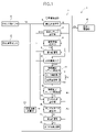
- FIG. 1 is a block diagram showing the configuration of an air-fuel ratio control device according to an embodiment of the invention
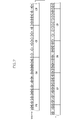
- FIG. 2 is a diagram showing execution stage values set by an execution stage setting unit of the air-fuel ratio control device of FIG. 1
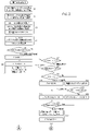
- FIG. 2 is a flowchart of the first half of signal value calculation processing in a signal value calculation unit of the air-fuel ratio control device of FIG. 1
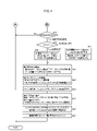
- FIG. 4 is a flowchart of the second half of the signal value calculation process in FIG. 3
- FIG. 3 and 4 show how control signal values to be supplied to the air-fuel ratio control unit of the air-fuel ratio control device are obtained by the signal calculation processing of FIG. 3 and FIG.
- FIG. 1 shows the configuration of an air-fuel ratio control system according to one embodiment of the present invention.
- This air-fuel ratio control device 1 reads a signal value VH from an oxygen concentration sensor 2 provided in contact with the exhaust gas of a four-cycle internal combustion engine, and determines the air-fuel ratio of the exhaust gas based on the read signal value VH. is.
- the air-fuel ratio control device 1 When obtaining the air-fuel ratio of the exhaust, the air-fuel ratio control device 1 detects changes in the signal value VH from the oxygen concentration sensor 2 with respect to the crank angle of the internal combustion engine during the period from when the exhaust valve of the internal combustion engine is opened until it is closed.
- a signal value calculator 3 is provided for calculating a control signal value CV for calculating the air-fuel ratio of the exhaust gas of the internal combustion engine based on the control signal value CV.
- the signal value calculator 3 eliminates as much as possible a signal caused by oxygen in gaseous gas other than exhaust gas from the signal value VH from the oxygen concentration sensor 2 based on the change in the signal value VH, and obtains a more appropriate signal value.
- the CV is supplied to an air-fuel ratio control section 4 in an ECU (electronic control unit) of a vehicle equipped with an internal combustion engine.
- a signal value calculator 3 generates an interrupt signal IS in response to a timing pulse (crank pulse) TP generated by a crank angle sensor 5 each time a crank shaft (not shown) of the internal combustion engine rotates by a predetermined angle (for example, 15 degrees).
- an execution stage setting unit 7 for setting the execution stage value STG for each interrupt signal IS; and an oxygen signal reading unit 8 for reading the signal value VH of the oxygen concentration sensor 2 in synchronization with the interrupt signal IS.
- a first storage unit 9 that stores the read signal value VH in chronological order while linking the read signal value VH to the execution stage value STG for each interrupt signal IS.
- the execution stage setting unit 7 circulates according to the four strokes of compression CP, explosion (combustion) CM, exhaust EX, and intake IN in a four-cycle internal combustion engine.
- An execution stage value STG is set for each signal IS.
- the stage value STG is set to "#0 (zero)" and is set to be incremented by #1 from the #0 (zero) stage in the direction in which the crankshaft rotates.
- the execution stage values STG corresponding to the compression stroke CP are set from #0 to #11, followed by the execution stage values STG corresponding to the explosion (combustion) stroke CM from #12 to #23, the exhaust stroke
- the execution stage values STG corresponding to EX are assigned to #24-35
- the execution stage values STG corresponding to intake stroke IN are assigned to #36-47, respectively. It presents a cyclic (loop) counter shape in which 0 stages are arranged.
- a total of 48 execution stage values STG, 12 for each stroke are set to cycle through each 720 degree rotation of the crankshaft.
- the signal value calculator 3 includes a rotational speed calculator 20 that calculates the rotational speed NE of the internal combustion engine based on the detection result of the crank angle sensor 5, and a change amount DVH of the signal value VH for each execution stage value STG.
- the change amount calculation unit 10 determines the timing at which the exhaust gas from the internal combustion engine is supplied to the vicinity of the oxygen concentration sensor 2 according to the change amount DVH, and uses the execution stage value STG corresponding to the timing as the reading start stage value BS. and a reading end stage setting unit 11 for setting a reading end stage value ES between the reading start stage value BS and the execution stage value STG corresponding to the timing immediately before the exhaust valve of the internal combustion engine is opened.
- a plurality of linked values are stored in the first storage unit 9 from the reading start stage value BS to the reading end stage value ES. and a first average value setting unit 13 for obtaining a first average value FV of the signal value VH of .
- the reading start stage setting unit 11 is a peak extracting unit that extracts a peak value PV of the amount of change DVH of the signal value VH stored in the first storage unit 9 after the exhaust valve is opened in the exhaust stroke EX. 14 and a threshold value setting unit 15 for setting a threshold value DVHJUD for the amount of change DVH based on the extracted peak value PV of the amount of change DVH.
- the execution stage value STG at which the DVH falls below the threshold value DVHJUD is set as the reading start stage value BS.
- the signal value calculator 3 also includes a sample size setter 16 that sets the number N of samples according to the operating state of the internal combustion engine, and a sample size setter 16 that calculates the first average value FV when the crankshaft rotates at least 720 degrees.
- a second storage unit 17 for sequentially storing the same first average value FV every time, and for the plurality of first average values FV stored in the second storage unit 17, the number of samples N from the latest first average value FV a second average value setting unit 18 that selects the first average values FV for the sample number N in chronological order, and obtains a second average value as an average value of the first average values FV of the sample number N that have been selected.
- the air-fuel ratio control unit 4 obtains the air-fuel ratio of the exhaust gas using the second average value as the signal value CV for control, and performs air-fuel ratio control.
- the setting of the number of samples N in the sample size setting unit 16 is performed, for example, according to the rotational speed NE.
- #3 is set as the sample number N, and the rotational speed NE is higher than in the idling state.
- #1 is set to the number N of samples.
- FIG. 3 and 4 show signal value calculation processing for obtaining the control signal value CV in the signal value calculator 3.
- FIG. This signal value calculation process is executed based on the crank pulse signal from the crank angle sensor 5 in synchronization with the four strokes of exhaust, intake, compression, and combustion in the internal combustion engine (two revolutions of the engine).
- step S1 the rotation speed NE of the internal combustion engine is obtained from the time interval between each pulse of the crank pulse TP (step S1). 7 (step S2).
- the oxygen signal reading unit 8 reads the latest value of the signal value VH from the oxygen concentration sensor 2, and the change amount DVH, which is the absolute value of the difference between the latest value of the signal value VH and the previously read signal value VH. is calculated (step S3).
- the latest value of the signal value VH is stored in the first storage unit 9 (ring buffer) in association with the execution stage value STG set in step S2 (step S4).
- step S5 it is checked whether or not the current execution stage value STG set in step S2 is the same as a predetermined EXSTSTG (for example, stage #24, which is the beginning of the exhaust stroke EX) (step S5). is the same as the predetermined EXSTSTG, the process advances to step S6 to set the flag F_EXINIT to "1" and the flag F_BLOWOF to "0 (zero)", and the peak of the peak extraction unit 14
- the value PV, the count value CTPEAK, and the threshold value DVHJUD are each reset to zero, and the current signal value calculation processing ends.
- step S9 if the change amount DVH is equal to or less than the peak value PV, the process proceeds to step S12 to set the threshold value DVHJUD according to the peak value PV.
- step S12 the process proceeds to step S13 to determine whether or not the amount of change DVH calculated in step S3 is greater than the threshold value DVHJUD. If it is determined in step S13 that the amount of change DVH is greater than the threshold value DVHJUD, the count value CTPEAK is reset to zero (step S11). If it is determined in step S13 that the amount of change DVH is equal to or less than the threshold value DVHJUD, the count value CTPEAK is incremented by +1 (step S14).
- step S16 it is determined whether or not the count value CTPEAK is greater than a predetermined value #CTPEAKH.
- the flag F_BLOWOF is set to "1" and reading is started according to the following formula (2) according to the current execution stage value STG set in step S2.
- step S18 it is determined whether or not the current execution stage value STG set in step S2 is the same as a predetermined EXENDSTG (for example, stage #23, which is the end of the explosion (combustion) stroke CM).
- a predetermined EXENDSTG for example, stage #23, which is the end of the explosion (combustion) stroke CM.
- the reading end stage value ES is set according to the following equation (3) (step S20).
- ES BS + EXRD STG (3)
- the EXSTSTG for example, is set as the reading start stage value BS
- the EXENDSTG for example, is set as the reading end stage value ES.
- step S22 among the plurality of signal values VH stored in the first storage unit 9 in step S4, each of the reading start stage value BS to the reading end stage value ES is stored in the first storage unit 9.
- the arithmetic mean value of the plurality of linked signal values VH is calculated by the first mean value setting unit 13 as the latest value of the first mean value FV, and the calculated latest value of the first mean value FV is used as the time.
- the data is stored in the second storage unit 17 (second ring buffer) provided to store data sequentially in series order (step S23).
- the latest value of the first average value FV is linked to the latest value of the sample number counter CTSP, which will be described later, and is sequentially stored in the second storage unit 17 .
- step S24 the number of samples N is set according to the rotation speed NE calculated in step S1.
- step S25 the number of samples N is set according to the rotation speed NE calculated in step S1.
- the sample number counter CTSP is a loop counter prepared to circulate with the maximum value of the sample number N in the sample size setting unit 16 as the upper limit.
- the sample number counter CTSP is For example, if the settable values of the number of samples N are #1 to #16, the values are set so as to circulate within the corresponding range of #0 to #15.
- the sample number counter CTSP incremented by #1 is set to the upper limit value (#16) of the sample number N preset by the sample size setting unit 16 (#16). #15) is determined, and if it is determined that it has exceeded, the sample number counter CTSP is set to #0. range).
- the second average value obtained as described above is supplied to the air-fuel ratio control section 4 as the signal value CV for control, and the current signal value calculation process ends.
- FIG. 5 shows how the signal value CV for control supplied to the air-fuel ratio control unit 4 is obtained by the signal value calculation process of FIGS.
- the signal value VH from the oxygen concentration sensor 2 corresponds to the timing pulse 19 from the crank angle sensor 5 of the internal combustion engine during the four strokes of exhaust EX, intake IN, compression CP, and combustion CM (two rotations of the engine). is shown with the timing of
- the oxygen concentration sensor 2 also reacts to oxygen in the gas other than the exhaust gas, and the signal value VH is mountain-shaped with the signal value thereof being superimposed.
- the amount of change DVH of the signal value VH for each pulse of the timing pulse (crank pulse) 19 after the exhaust stroke EX is started is read (step S3), and the amount of change DVH is read.
- the reading start stage is started at the timing when the change amount DVH becomes equal to or less than the threshold value DVHJUD a predetermined number of times (steps S11 to S16).
- step S17 By setting BS (step S17), the signal value VH obtained by excluding the signal value VH in the period T1 in FIG. A first average value FV is obtained from the signal value VH read during the period T2 in FIG. 5 up to the end stage ES (step S22).
- a second average value is obtained by arithmetically averaging the first average values FV for N samples (steps S24 and S25). This second average value is supplied to the air-fuel ratio controller 4 as the signal value CV for control, as described above.
- the timing of reading the signal value VH caused by gaseous oxygen other than exhaust gas can be eliminated based on the change in the signal value VH. It does not require the trouble of finely entering and setting separately according to the time. Thereby, the scalability of the air-fuel ratio control device 1 can be improved.
- the read start stage value BS set according to the change amount DVH of the signal value VH of the oxygen concentration sensor 2 is changed to the read end stage value. Since the signal value VH read before reaching ES is used, the signal value VH can be obtained while reliably excluding the period T1 including the signal value due to gaseous oxygen that is not exhaust gas. Moreover, the air-fuel ratio of the exhaust gas can be accurately calculated based on the first average value FV of the plurality of read signal values VH.
- the air-fuel ratio can be obtained more accurately by obtaining the air-fuel ratio using the value obtained by further averaging the first average value FV over the selected number of samples N.
- the present invention is not limited to this.
- the first signal value FV may be directly supplied to the air-fuel ratio controller 4 as the control signal value CV.
- various configurations can be adopted without departing from the gist of the present invention.
Landscapes
- Engineering & Computer Science (AREA)
- Chemical & Material Sciences (AREA)
- Combustion & Propulsion (AREA)
- Mechanical Engineering (AREA)
- General Engineering & Computer Science (AREA)
- Combined Controls Of Internal Combustion Engines (AREA)
- Electrical Control Of Air Or Fuel Supplied To Internal-Combustion Engine (AREA)
Abstract
内燃エンジンの仕様に拘わらず、長期にわたって、正確に空燃比を検出することができる空燃比制御装置(1)提供する。 空燃比制御装置(1)は、4サイクル形式の内燃エンジンの排気に接するように設けられた酸素濃度センサ(2)からの信号値を読み取り、読み取った信号値VHに基づき、空燃比制御部(4)により排気の空燃比を算出する。この算出は、内燃エンジンの排気弁が開いてから閉じられるまでの期間T1における、内燃エンジンのクランク角に対する酸素濃度センサ(2)からの信号値VHの変化に基づいて、排気ではない気体中の酸素に基づく信号値VHを排除し、排除した後の信号値VHに基づいて行われる。
Description
本発明は、4サイクル形式の内燃エンジンにおける排気の空燃比を酸素濃度センサからの信号値に基づいて求める空燃比制御装置に関する。
従来、内燃エンジンの排気に接するように設けられた酸素濃度センサを用いて得られる空燃比に基づいて、内燃機関に供給される混合気の空燃比を制御する空燃比制御装置が知られている(例えば、特許文献1)。
特許文献1の空燃比制御装置では、酸素濃度センサの出力をクランク軸の回転に同期しかつエンジンの上死点の周期より短い所定の周期で読み込み、読み込んだ酸素濃度センサ出力の上死点周期間の積算値を算出し、この積算値を酸素濃度センサの濃度ばらつき及び大気圧で補正し、補正後の積算値に対応するテーブル値をリミット処理した値に基づいて空燃比を求めている。
また、内燃エンジンの空燃比を検出する装置として、内燃エンジンの排気系に配置された空燃比センサの出力をサンプリングして空燃比を検出する装置が知られている(特許文献2参照)。特許文献2の装置では、内燃エンジンの所定クランク角度ごとに、空燃比センサの出力を順次サンプリングして記憶し、記憶されたサンプリング値群の中のいずれかを機関回転数及び機関負荷に応じて選択し、選択されたサンプリング値に基づいて空燃比が検出される。
上記特許文献1、2の技術によれば、センサの出力を所定の上死点の周期や所定のクランク角位置に基づいてサンプリングしている。しかしながら、好適なサンプリングのタイミングは、内燃エンジンの回転速度のみならずスロットル開度やセンサの応答特性の劣化等によっても変化する。このため、空燃比を長期間にわたって高精度に検出するためには、かかるタイミングの変化に応じてサンプリングのタイミングを較正又は補正する必要があるが、このような較正や補正は困難である。
しかも、制御対象である内燃エンジンの排気量や排気管寸法の仕様などが変更する毎に、サンプリングのタイミングを、その仕様の変化に合わせて較正し直す必要がある。このため、較正や補正に関するセッティングデータの汎用性がないなど、装置の応用範囲が狭く、スケーラビリティに乏しい。
また、上記特許文献2の技術によれば、所定クランク角度毎に1点でサンプリングを行うので、サンプリング時の量子化誤差などが大きい影響を与え、正確な空燃比の算出に支障を来す。
本発明の目的は、かかる従来技術の問題点に鑑み、内燃エンジンの仕様に拘わらず、長期にわたって、正確に空燃比を検出することができる空燃比制御装置を提供することにある。
本発明の空燃比制御装置は、
4サイクル形式の内燃エンジンの排気に接するように設けられた酸素濃度センサからの信号値を読み取り、読み取った信号値に基づいて前記排気の空燃比を求める空燃比制御装置であって、
前記内燃エンジンの排気弁が開いてから閉じられるまでの期間における、前記内燃エンジンのクランク角に対する前記酸素濃度センサからの信号値の変化に基づいて前記排気の空燃比を算出することを特徴とする。
4サイクル形式の内燃エンジンの排気に接するように設けられた酸素濃度センサからの信号値を読み取り、読み取った信号値に基づいて前記排気の空燃比を求める空燃比制御装置であって、
前記内燃エンジンの排気弁が開いてから閉じられるまでの期間における、前記内燃エンジンのクランク角に対する前記酸素濃度センサからの信号値の変化に基づいて前記排気の空燃比を算出することを特徴とする。
一般に、4サイクル形式の内燃エンジンにおいては、排気弁と、排気通路に配置される酸素濃度センサとの間に、今回(直近)の排気行程で排出された排気ではない気体、例えば前回の排気行程での排気や、排気管内に逆流入した外気が存在する。酸素濃度センサは、排気弁が開いた直後に、そのような今回の排気ではない気体中の酸素にも反応する。
したがって、酸素濃度センサからの信号値に基づいて排気の空燃比(空気過剰率)を算出する場合には、上記のような今回の排気ではない気体の酸素に起因する信号は、本来読み取るべき信号についてのノイズとなるので排除することが望ましい。このことは、酸素濃度センサとして、酸素濃淡電池型センサ(例えば、ジルコニア酸素センサ)に比べて応答性が高い抵抗型酸素センサ(例えば、チタニア酸素センサ)を使用する場合により強く望まれる。
そこで、本発明では、排気弁が開いてから閉じられるまでの期間における、クランク角に対する酸素濃度センサからの信号値の変化に基づいて排気の空燃比(空気過剰率)が算出される。この信号値の変化に基づけば、排気の空燃比を求めるために読み取る信号値に、排気ではない気体の酸素に起因する信号値が含まれる期間を確実に除外して読み取りを行うことができる。このようにして読み取った信号値に基づけば、長期間にわたって正確に排気の空燃比を算出できるので、算出される空燃比に基づいて空燃比制御を適切に行うことができる。
しかも、信号値の変化に基づいて、排気ではない気体の酸素に起因する信号値を読み込むタイミングを排除できるので、従来のように酸素濃度センサからの信号値読み込みのタイミングを、車種の仕様に合わせて微に入り細に入り別個に設定する手間を要しない。これにより、空燃比制御装置のスケーラビリティを向上させることができる。
本発明において、
前記内燃エンジンのクランク角センサのタイミングパルスに応じて割込み信号を発生する割込み発生部と、
前記割込み信号毎に、前記内燃エンジンにおける圧縮、爆発、排気、吸気の4つの行程に応じて循環するように実行ステージ値を設定する実行ステージ設定部と、
前記酸素濃度センサの信号値を、前記割込み信号に同期して読み取る酸素信号読取部と、
前記割込み信号毎に、読み取った前記信号値を前記実行ステージ値に紐付けしつつ時系列順に記憶する第1記憶部と、
前記割込み信号毎に、前記信号値の変化量を算出する変化量算出部と、
前記変化量に応じて、前記排気が前記酸素濃度センサ付近に供給されるタイミングを決定し、同タイミングに該当する前記実行ステージ値を読取開始ステージ値として設定する読取開始ステージ設定部と、
前記読取開始ステージ値に応じて、内燃エンジンの排気弁が閉じられるタイミングに該当する前記実行ステージ値を読取終了ステージ値として設定する読取終了ステージ設定部と、
前記読取終了ステージ値に前記実行ステージ値の現在値が一致したときに、前記第1記憶部内で前記読取開始ステージ値から前記読取終了ステージ値まで各紐付けされた複数個の前記信号値の第1平均値を求める第1平均値設定部とを備えてもよい。
これによれば、酸素濃度センサの信号値の変化量に応じて読取開始ステージ値を設定した読取開始ステージ値から読取終了ステージ値に至るまでの間に読み取られる信号値に基づいて、排気ではない気体の酸素に起因する信号値が含まれる期間を確実に除外した信号値を取得することができる。また、読み取った複数個の信号値の第1平均値に基づいて、正確に排気の空燃比を算出することができる。
この場合、前記読取開始ステージ設定部は、前記第1記憶部に記憶される前記変化量について、前記排気行程からの変化量のピーク値を抽出するピーク抽出部と、前記抽出した変化量のピーク値に基づいて、前記変化量についての閾値を設定する閾値設定部とを有し、前記変化量が前記閾値を連続して下回るに至る前記実行ステージ値を前記読取開始ステージ値として設定してもよい。
これによれば、今回(直近)の燃焼に係る排気ではない気体の酸素に起因する酸素濃度センサの信号を変化量のピーク値として感知し、例えばこのピーク値を避けるように読取開始ステージを適切に設定することができる。これにより、排気ではない気体の酸素に起因する信号値が含まれる期間を確実に除外して信号値を取得するとともに、正確な空燃比を算出することができる。
この場合、前記内燃エンジンの運転状態に応じて、サンプル個数を設定するサンプルサイズ設定部と、少なくとも前記サンプル個数の前記第1平均値を算出する毎に該第1平均値を順次記憶する第2記憶部と、前記第2記憶部から、最新の前記第1平均値から前記サンプル個数の前記第1平均値を時系列順に遡って選出し、選出した前記サンプル個数の前記第1平均値の平均値として、第2平均値を求める第2平均値設定部とを有し、前記第2平均値に基づいて前記排気の空燃比を求めてもよい。
これによれば、第1平均値を、選出したサンプル個数分にわたってさらに平均した値を用いて空燃比を求めるので、空燃比をより正確に求めることができる。
以下、図面を用いて本発明の実施形態を説明する。図1は、本発明の一実施形態に係る空燃比制御装置の構成を示す。この空燃比制御装置1は、4サイクル形式の内燃エンジンの排気に接するように設けられた酸素濃度センサ2からの信号値VHを読み取り、読み取った信号値VHに基づいて排気の空燃比を求めるものである。
空燃比制御装置1は、排気の空燃比を求める際に、内燃エンジンの排気弁が開いてから閉じられるまでの期間における、内燃エンジンのクランク角に対する酸素濃度センサ2からの信号値VHの変化に基づいて内燃エンジンの排気の空燃比を算出するための制御用信号値CVを求める信号値算出部3を備える。
信号値算出部3は、酸素濃度センサ2からの信号値VHから、排気ではない気体の酸素に起因する信号を信号値VHの変化に基づいて極力排除し、これにより得られたより適切な信号値CVを、内燃エンジンが搭載された車両のECU(エレクトロニック・コントロール・ユニット)における空燃比制御部4に供するものである。
信号値算出部3は、内燃エンジンの不図示のクランク軸が所定角度(例えば、15度)回転する毎にクランク角センサ5が発生するタイミングパルス(クランクパルス)TPに応じて割込み信号ISを発生する割込み発生部6と、割込み信号IS毎に実行ステージ値STGを設定する実行ステージ設定部7と、酸素濃度センサ2の信号値VHを、割込み信号ISに同期して読み取る酸素信号読取部8と、割込み信号IS毎に、読み取った信号値VHを実行ステージ値STGに紐付けしつつ時系列順に記憶する第1記憶部9とを備える。
図2を併せて参照して、実行ステージ設定部7は、4サイクル形式の内燃エンジンにおける圧縮CP、爆発(燃焼)CM、排気EX、吸気INの4つの行程に応じて循環する如くに前記割込み信号IS毎に実行ステージ値STGを設定するものであり、例えば、圧縮行程CPの先頭(吸気行程INの直後)で、内燃エンジンの不図示のピストンが下死点に至るクランク角に対応する実行ステージ値STGを「#0(ゼロ)」として、該#0(ゼロ)ステージからクランク軸の回転進行方向に向かって#1ずつインクリメントされるように設定される。この実施の形態においては、圧縮行程CPに対応する実行ステージ値STGは#0~11まで設定され、続いて、爆発(燃焼)行程CMに対応する実行ステージ値STGは#12~23、排気行程EXに対応する実行ステージ値STGは#24~35、吸気行程INに対応する実行ステージ値STGは#36~47にそれぞれ割り当てされ、しかも、吸気行程INの#47ステージ直後に圧縮行程CPの#0ステージが配列される循環(ループ)カウンタ状を呈する。斯くして、各行程に12個ずつ計48個の実行ステージ値STGが、前記クランク軸が720度回転する毎に循環するように設定される。
信号値算出部3は、クランク角度センサ5の検出結果に基づいて内燃エンジンの回転速度NEを算出する回転速度演算部20と、実行ステージ値STG毎に、信号値VHの変化量DVHを算出する変化量算出部10と、この変化量DVHに応じて、内燃エンジンの排気が酸素濃度センサ2付近に供給されるタイミングを決定し、同タイミングに該当する実行ステージ値STGを読取開始ステージ値BSとして設定する読取開始ステージ設定部11と、この読取開始ステージ値BSから内燃エンジンの排気弁が開かれる直前のタイミングに該当する実行ステージ値STGまでの間で読取終了ステージ値ESを設定する読取終了ステージ設定部12と、読取終了ステージ値ESに実行ステージ値STGの現在値が一致したときに、第1記憶部9内で読取開始ステージ値BSから読取終了ステージ値ESまで各紐付けされた複数個の信号値VHの第1平均値FVを求める第1平均値設定部13とを備える。
読取開始ステージ設定部11は、第1記憶部9に記憶される信号値VHの変化量DVHについて、排気行程EXで排気弁が開いてからの変化量DVHのピーク値PVを抽出するピーク抽出部14と、抽出した変化量DVHのピーク値PVに基づいて、変化量DVHについての閾値DVHJUDを設定する閾値設定部15とを有し、直近の排気行程EXで排気弁が開いてからの変化量DVHが、閾値DVHJUDを下回るに至る実行ステージ値STGを読取開始ステージ値BSとして設定するものである。
また、信号値算出部3は、前記内燃エンジンの運転状態に応じてサンプル個数Nを設定するサンプルサイズ設定部16と、少なくともクランク軸が720度回転して前記第1平均値FVが算出される毎に同第1平均値FVを順次記憶する第2記憶部17と、該第2記憶部17に記憶された複数個の第1平均値FVについて、最新の第1平均値FVからサンプル個数N個分の第1平均値FVを時系列順に遡って選出し、該選出したサンプル個数Nの第1平均値FVの平均値としての第2平均値を求める第2平均値設定部18とを有する。後述するように、空燃比制御部4は、第2平均値を制御用の信号値CVとして、排気の空燃比を求め、空燃比制御を行う。
サンプルサイズ設定部16におけるサンプル個数Nの設定は、例えば、回転速度NEに応じて行われる。この実施の形態においては、例えば、内燃エンジンの回転速度NEが比較的低いアイドリング状態である場合、サンプル個数Nとしては#3(個)が設定され、また、回転速度NEがアイドリング状態よりも上昇した場合は、例えばサンプル個数Nに#1(個)が設定される。
図3、図4は、信号値算出部3における制御用信号値CVを求める信号値算出処理を示す。この信号値算出処理は、クランク角センサ5からのクランクパルス信号に基づき、内燃エンジンにおける排気、吸気、圧縮、燃焼の4つの行程(エンジン2回転)に同期して実行される。
信号値算出処理が開始されると、まず、クランクパルスTPの各パルス間の時間間隔から内燃エンジンの回転速度NEを求め(ステップS1)、また、現時点での実行ステージ値STGを実行ステージ設定部7により設定する(ステップS2)。
次に、酸素信号読取部8により、酸素濃度センサ2からの信号値VHの最新値を読み取り、該信号値VHの最新値と前回読み取った信号値VHとの差の絶対値である変化量DVHを算出する(ステップS3)。ここで、信号値VHの最新値は、ステップS2で設定された実行ステージ値STGに紐付けさせて、第1記憶部9(リングバッファ)に記憶される(ステップS4)。
次に、ステップS2で設定された現在の実行ステージ値STGが、所定のEXSTSTG(たとえば、排気行程EXの先頭である#24ステージ)と同一であるか否かを確認し(ステップS5)、現在の実行ステージ値STGが所定のEXSTSTGと同一である場合には、ステップS6に進み、フラグF_EXINITを「1」、フラグF_BLOWOFを「0(ゼロ)」に設定し、且つ、ピーク抽出部14のピーク値PV、計数値CTPEAK及び、閾値DVHJUDをそれぞれゼロにリセットして、今回の信号値算出処理を終了する。
ステップS5において、現在の実行ステージ値STGが所定のEXSTSTGと同一ではないと判定した場合には、ステップS7に進み、フラグF_EXINIT=1であるか否かを判定する。F_EXINIT=0であるならば、ピーク値PV等が初期設定されていないことを示すので、排気行程EXからの変化量DVHのピーク値PVを抽出することができない。この場合、フラグF_BLOWOFを「0(ゼロ)」に設定し、且つ、ピーク抽出部14のピーク値PV、計数値CTPEAK及び、閾値DVHJUDをそれぞれゼロにリセットして、今回の信号値算出処理を終了する。
ステップS7において、F_EXINIT=1であるならば、ステップS8に進み、フラグF_BLOWOF=1であるか否かを判定する。F_BLOWOF=0であるならば、ステップS9に進み、ステップS3で算出された変化量DVHがピーク値PVよりも大きいか否かを判定する。変化量DVHがピーク値PVよりも大きい場合には、ピーク値PVの値を変化量DVHの値に上書き更新する(ステップS10)とともに計数値(カウンタ)CTPEAKをゼロにリセットする(ステップS11)。
ステップS9において、変化量DVHがピーク値PV以下である場合には、ステップS12に進み、ピーク値PVに応じて閾値DVHJUDを設定する。この閾値DVHJUDは、例えば、所定の閾値演算係数を#MDVHとした場合、閾値設定部15において次式(1)により求められる。
DVHJUD=PV×#MDVH (1)
DVHJUD=PV×#MDVH (1)
ステップS12において閾値DVHJUDが設定された場合には、ステップS13に進み、ステップS3で算出された変化量DVHが閾値DVHJUDよりも大きいか否かを判定する。ステップS13において、変化量DVHが閾値DVHJUDよりも大きいと判定した場合には、計数値CTPEAKをゼロにリセットする(ステップS11)。ステップS13において、変化量DVHが閾値DVHJUD以下と判定した場合には、計数値CTPEAKをプラス1だけインクリメントする(ステップS14)。
次に、ステップS16へと進み、計数値CTPEAKが所定値#CTPEAKHよりも大きいか否かを判定する。計数値CTPEAKが所定値#CTPEAKH以上である場合には、フラグF_BLOWOFを「1」に設定し、且つ、ステップS2で設定された現在の実行ステージ値STGに応じて次式(2)により読取開始ステージ値BSが設定される(ステップS17)。
BS=STG-#CTPEAKH (2)
BS=STG-#CTPEAKH (2)
次に、ステップS18に進み、ステップS2で設定された現在の実行ステージ値STGが、所定のEXENDSTG(たとえば、爆発(燃焼)行程CMの末尾である#23ステージ)と同一であるか否かを確認し、現在の実行ステージ値STGが所定のEXENDSTGと同一である場合には、ステップS19に進み、フラグF_BLOWOF=1であるか否かを判定する。ステップS19において、F_BLOWOF=1であるならば、ここまでに読取開始ステージ値BSが設定済であることを示すので、ステップS17で設定された読取開始ステージ値BSに応じて、例えば、所定の実行ステージ数をEXRDSTGとした場合、次式(3)により、読取終了ステージ値ESが設定される(ステップS20)。
ES=BS+EXRDSTG (3)
ES=BS+EXRDSTG (3)
ステップS19において、フラグF_BLOWOF=0である場合には、ステップS21に進み、読取開始ステージ値BSを代替値に設定する。ステップ21において、読取開始ステージ値BSとして例えば前記EXSTSTGが設定され、且つ、読取終了ステージ値ESとして例えば前記EXENDSTGが設定される。
次に、ステップS22に進み、ステップS4において第1記憶部9内へ記憶された複数個の信号値VHのうち、第1記憶部9内で読取開始ステージ値BSから読取終了ステージ値ESまで各紐付けされた複数個の信号値VHの相加平均値が第1平均値FVの最新値として第1平均値設定部13により算出され、該算出された第1平均値FVの最新値を時系列順に順次記憶するように設けられた第2記憶部17(第2リングバッファ)へ記憶する(ステップS23)。ステップ23において、第1平均値FVの最新値は、後述するサンプル個数カウンタCTSPの最新値に紐付けさせて、第2記憶部17に順次記憶される。
次にステップS24に進み、ステップS1で算出された回転速度NEに応じて、サンプル個数Nを設定する。次に、ステップS23において第2記憶部17に記憶された複数個の第1平均値FVのうち、第2記憶部17内で、第1平均値FVの最新値からサンプル個数N個前までの分を時系列順に遡及したサンプル個数N個の第1平均値FVの相加平均値を求め、これを第2平均値として設定する(ステップS25)。
次にステップS26に進み、サンプル個数カウンタCTSPを#1だけインクリメントする。なお、サンプル個数カウンタCTSPは、上記サンプルサイズ設定部16におけるサンプル個数Nの最大値を上限として循環するように準備された循環(ループ)カウンタであり、この実施の形態において上記サンプル個数カウンタCTSPは、例えば、上記サンプル個数Nの設定可能な値を#1~#16個であるとすれば、これに対応する#0~#15の範囲で循環するように設定されるものである。而して上記ステップS26の場合においては、上記#1だけインクリメントされたサンプル個数カウンタCTSPが、サンプルサイズ設定部16により予め設定されたサンプル個数Nの最大値(上記#16)に関する上限値(上記#15)を超えたか否かが判定され、超えたと判定された場合には、サンプル個数カウンタCTSPは#0に設定され、斯くしてサンプル個数カウンタCTSPは所定値の範囲(#0~#15の範囲)で循環(ループ)される。
以上のように求められた第2平均値は、制御用の信号値CVとして空燃比制御部4に供給され、今回の信号値算出処理を終了する。
図5は、図3、図4の信号値算出処理によって、空燃比制御部4に供給される制御用の信号値CVを求める様子を示す。図5においては、内燃エンジンのクランク角センサ5からのタイミングパルス19に対し、酸素濃度センサ2からの信号値VHが、排気EX、吸気IN、圧縮CP、燃焼CMの4行程(エンジン2回転)のタイミングとともに示されている。
各排気行程EXにおいては、酸素濃度センサ2が排気ではない気体中の酸素にも反応し、その信号値分が重畳されて信号値VHが山型になっていることが諒解される。図3の信号算出処理では、排気行程EXが開始されてから、タイミングパルス(クランクパルス)19の1パルス毎の信号値VHの変化量DVHが読み取られ(ステップS3)、且つ、変化量DVHのピーク値PVが読み取られ(ステップS9~S10)、ピーク値PVに応じて閾値DVHJUDを求めるのに続いて、変化量DVHが所定回数閾値DVHJUD以下となるタイミング(ステップS11~S16)に読み取り開始ステージBSを設定(ステップS17)するという構成により、排気ではない気体中の酸素に酸素濃度センサ2が反応する図5において期間T1の信号値VHを排除した信号値VH、すなわち読取開始ステージBSから読取終了ステージESまでの図5において期間T2に読み取られる信号値VHにより第1平均値FVが求められる(ステップS22)。
しかも、図5に示す複数の各期間T2の信号値VHからそれぞれ求められる複数の第1平均値FVは、第2記憶部17に時系列順に蓄積記憶され(ステップS23)、さらに、記憶されたサンプル個数N個分の第1平均値FVを相加平均した第2平均値が求められる(ステップS24~S25)。この第2平均値は上述のように、制御用の信号値CVとして空燃比制御部4に供給される。
以上説明したように、本実施形態によれば、排気弁が開いてからの期間における、クランク角に対する酸素濃度センサからの信号値VHの変化に基づき、内燃エンジンの排気ではない気体の酸素に起因する信号値が含まれる期間T1を除外して信号値VHの読み取りを行うので、このようにして読み取った信号値VHにより算出される制御用の信号値CVに基づき、空燃比制御部4は、長期間にわたって正確に排気の空燃比を算出し、空燃比制御を適切に行うことができる。
しかも、信号値VHの変化に基づいて、排気ではない気体の酸素に起因する信号値VHを読み込むタイミングを排除できるので、従来のように酸素濃度センサからの信号値読み込みのタイミングを、車種の仕様に合わせて微に入り細に入り別個に設定する手間を要しない。これにより、空燃比制御装置1のスケーラビリティを向上させることができる。
また、排気ではない気体の酸素に起因する信号値VHを読み込むタイミングを排除するために、酸素濃度センサ2の信号値VHの変化量DVHに応じて設定した読取開始ステージ値BSから読取終了ステージ値ESに至るまでの間に読み取られる信号値VHを用いているので、排気ではない気体の酸素に起因する信号値が含まれる期間T1を確実に除外して信号値VHを取得することができる。また、読み取った複数個の信号値VHの第1平均値FVに基づいて、正確に排気の空燃比を算出することができる。
また、第1平均値FVを、選出したサンプル個数N分にわたってさらに平均した値を用いて空燃比を求めることにより、空燃比をより正確に求めることができる。
以上、本発明の実施形態について説明したが、本発明はこれに限定されない。例えば、第1信号値FVをそのまま制御用の信号値CVとして空燃比制御部4に供給してもよい。このように、本発明の要旨を逸脱することなく、種々の構成を採り得ることはもちろんである。
1…空燃比制御装置、2…酸素濃度センサ、3…信号値算出部、4…空燃比制御部、5…クランク角センサ、6…割込み発生部、7…実行ステージ設定部、8…酸素信号読取部、9…第1記憶部、10…変化量算出部、11…読取開始ステージ設定部、12…読取終了ステージ設定部、13…第1平均値設定部、14…ピーク抽出部、15…閾値設定部、16…サンプルサイズ設定部、17…第2記憶部、18…第2平均値設定部、19…タイミングパルス、20…回転速度演算部。
Claims (4)
- 4サイクル形式の内燃エンジンの排気に接するように設けられた酸素濃度センサからの信号値を読み取り、読み取った信号値に基づいて前記排気の空燃比を求める空燃比制御装置であって、
前記内燃エンジンの排気弁が開いてから閉じられるまでの期間における、前記内燃エンジンのクランク角に対する前記酸素濃度センサからの信号値の変化に基づいて前記排気の空燃比を算出することを特徴とする空燃比制御装置。 - 前記内燃エンジンのクランク角センサのタイミングパルスに応じて割込み信号を発生する割込み発生部と、
前記割込み信号毎に、前記内燃エンジンにおける圧縮、爆発、排気、吸気の4つの行程に応じて循環するように実行ステージ値を設定する実行ステージ設定部と、
前記酸素濃度センサの信号値を、前記割込み信号に同期して読み取る酸素信号読取部と、
前記割込み信号毎に、読み取った前記信号値を前記実行ステージ値に紐付けしつつ時系列順に記憶する第1記憶部と、
前記割込み信号毎に、前記信号値の変化量を算出する変化量算出部と、
前記変化量に応じて、前記排気が前記酸素濃度センサ付近に供給されるタイミングを決定し、同タイミングに該当する前記実行ステージ値を読取開始ステージ値として設定する読取開始ステージ設定部と、
前記読取開始ステージ値に応じて、内燃エンジンの排気弁が閉じられるタイミングに該当する前記実行ステージ値を読取終了ステージ値として設定する読取終了ステージ設定部と、
前記読取終了ステージ値に前記実行ステージ値の現在値が一致したときに、前記第1記憶部内で前記読取開始ステージ値から前記読取終了ステージ値まで各紐付けされた複数個の前記信号値の第1平均値を求める第1平均値設定部とを備えることを特徴とする請求項1に記載の空燃比制御装置。 - 前記読取開始ステージ設定部は、
前記第1記憶部に記憶される前記信号値の前記変化量について、前記排気行程からの変化量のピーク値を抽出するピーク抽出部と、
前記抽出した変化量のピーク値に基づいて、前記変化量についての閾値を設定する閾値設定部とを有し、
前記変化量が前記閾値を連続して下回るに至る前記実行ステージ値を前記読取開始ステージ値として設定することを特徴とする請求項2に記載の空燃比制御装置。 - 前記内燃エンジンの運転状態に応じて、サンプル個数を設定するサンプルサイズ設定部と、
少なくとも前記サンプル個数の前記第1平均値を算出する毎に該第1平均値を順次記憶する第2記憶部と、
前記第2記憶部から、最新の前記第1平均値から前記サンプル個数の前記第1平均値を時系列順に遡って選出し、選出した前記サンプル個数の前記第1平均値の平均値として、第2平均値を求める第2平均値設定部とを有し、
前記第2平均値に基づいて前記排気の空燃比を求めることを特徴とする請求項3に記載の空燃比制御装置。
Priority Applications (1)
| Application Number | Priority Date | Filing Date | Title |
|---|---|---|---|
| DE112022001952.2T DE112022001952T5 (de) | 2021-03-31 | 2022-02-14 | Luft-kraftstoff-verhältnis-regelungsvorrichtung |
Applications Claiming Priority (2)
| Application Number | Priority Date | Filing Date | Title |
|---|---|---|---|
| JP2021061900A JP7649677B2 (ja) | 2021-03-31 | 2021-03-31 | 空燃比制御装置 |
| JP2021-061900 | 2021-03-31 |
Publications (1)
| Publication Number | Publication Date |
|---|---|
| WO2022209358A1 true WO2022209358A1 (ja) | 2022-10-06 |
Family
ID=83455905
Family Applications (1)
| Application Number | Title | Priority Date | Filing Date |
|---|---|---|---|
| PCT/JP2022/005698 Ceased WO2022209358A1 (ja) | 2021-03-31 | 2022-02-14 | 空燃比制御装置 |
Country Status (3)
| Country | Link |
|---|---|
| JP (1) | JP7649677B2 (ja) |
| DE (1) | DE112022001952T5 (ja) |
| WO (1) | WO2022209358A1 (ja) |
Citations (1)
| Publication number | Priority date | Publication date | Assignee | Title |
|---|---|---|---|---|
| JP2005337080A (ja) * | 2004-05-26 | 2005-12-08 | Mikuni Corp | 内燃機関における空燃比制御装置及び空燃比制御方法 |
Family Cites Families (2)
| Publication number | Priority date | Publication date | Assignee | Title |
|---|---|---|---|---|
| JP3976708B2 (ja) | 2003-06-03 | 2007-09-19 | 本田技研工業株式会社 | 内燃機関の空燃比制御装置 |
| JP7259588B2 (ja) | 2019-06-24 | 2023-04-18 | 株式会社レゾナック | 繊維製品及びその製造方法、並びに接着剤セット |
-
2021
- 2021-03-31 JP JP2021061900A patent/JP7649677B2/ja active Active
-
2022
- 2022-02-14 WO PCT/JP2022/005698 patent/WO2022209358A1/ja not_active Ceased
- 2022-02-14 DE DE112022001952.2T patent/DE112022001952T5/de active Pending
Patent Citations (1)
| Publication number | Priority date | Publication date | Assignee | Title |
|---|---|---|---|---|
| JP2005337080A (ja) * | 2004-05-26 | 2005-12-08 | Mikuni Corp | 内燃機関における空燃比制御装置及び空燃比制御方法 |
Also Published As
| Publication number | Publication date |
|---|---|
| DE112022001952T5 (de) | 2024-01-25 |
| JP2022157590A (ja) | 2022-10-14 |
| JP7649677B2 (ja) | 2025-03-21 |
Similar Documents
| Publication | Publication Date | Title |
|---|---|---|
| US5870688A (en) | Misfire diagnostic system for internal combustion engine | |
| JPS62192627A (ja) | 内燃機関の気筒内圧力の補正方法 | |
| EP2037107A2 (en) | A control for an internal-combustion engine | |
| JPH11506510A (ja) | 燃料送給電子制御ユニット及び燃料送給電子制御方法 | |
| EP2481907A1 (en) | Control device for internal combustion engine | |
| CN106103956A (zh) | 内燃机的空燃比检测装置 | |
| JP4484772B2 (ja) | 内燃機関の失火検出装置 | |
| JPH0783108A (ja) | 内燃エンジンの燃焼状態検出装置 | |
| US7448360B2 (en) | Controller of internal combustion engine | |
| JP2022157590A (ja) | 空燃比制御装置 | |
| JP2007211654A (ja) | 内燃機関の空燃比制御装置 | |
| US20060081203A1 (en) | Variable valve timing controller for internal combustion engine | |
| JP2001123879A (ja) | 内燃機関の燃焼状態検出装置 | |
| JP2586617B2 (ja) | 内燃機関の出力変動検出装置 | |
| KR20050057460A (ko) | 스로틀 개방도 추정방법 및 ecu | |
| EP1930576B1 (en) | Control Apparatus and Method for Internal Combustion Engine | |
| JP4340577B2 (ja) | 筒内圧センサの温度検知装置、ならびにこれを用いた筒内圧の検出装置および内燃機関の制御装置 | |
| US12163858B2 (en) | Misfire determination device for internal combustion engine | |
| JPH0742892B2 (ja) | 吸入空気量検出装置 | |
| JP2937011B2 (ja) | エンジンの空燃比制御装置 | |
| JP2586624B2 (ja) | 内燃機関の出力変動検出装置 | |
| JP2586565B2 (ja) | 内燃機関の出力変動検出装置 | |
| JP2001193548A (ja) | 内燃機関の燃焼状態検出装置 | |
| JP2000356163A (ja) | 燃料蒸発特性検出装置及び内燃機関の制御装置 | |
| JPH0495838A (ja) | 内燃機関の筒内圧検出装置 |
Legal Events
| Date | Code | Title | Description |
|---|---|---|---|
| 121 | Ep: the epo has been informed by wipo that ep was designated in this application |
Ref document number: 22779585 Country of ref document: EP Kind code of ref document: A1 |
|
| WWE | Wipo information: entry into national phase |
Ref document number: 202347073218 Country of ref document: IN |
|
| WWE | Wipo information: entry into national phase |
Ref document number: 112022001952 Country of ref document: DE |
|
| 122 | Ep: pct application non-entry in european phase |
Ref document number: 22779585 Country of ref document: EP Kind code of ref document: A1 |