WO2022208752A1 - 情報生成システム、情報生成システムにおける情報処理方法及びプログラム - Google Patents
情報生成システム、情報生成システムにおける情報処理方法及びプログラム Download PDFInfo
- Publication number
- WO2022208752A1 WO2022208752A1 PCT/JP2021/013890 JP2021013890W WO2022208752A1 WO 2022208752 A1 WO2022208752 A1 WO 2022208752A1 JP 2021013890 W JP2021013890 W JP 2021013890W WO 2022208752 A1 WO2022208752 A1 WO 2022208752A1
- Authority
- WO
- WIPO (PCT)
- Prior art keywords
- information
- evaluation
- customer
- route
- payment
- Prior art date
- Legal status (The legal status is an assumption and is not a legal conclusion. Google has not performed a legal analysis and makes no representation as to the accuracy of the status listed.)
- Ceased
Links
Images



Classifications
-
- G—PHYSICS
- G06—COMPUTING OR CALCULATING; COUNTING
- G06Q—INFORMATION AND COMMUNICATION TECHNOLOGY [ICT] SPECIALLY ADAPTED FOR ADMINISTRATIVE, COMMERCIAL, FINANCIAL, MANAGERIAL OR SUPERVISORY PURPOSES; SYSTEMS OR METHODS SPECIALLY ADAPTED FOR ADMINISTRATIVE, COMMERCIAL, FINANCIAL, MANAGERIAL OR SUPERVISORY PURPOSES, NOT OTHERWISE PROVIDED FOR
- G06Q40/00—Finance; Insurance; Tax strategies; Processing of corporate or income taxes
- G06Q40/02—Banking, e.g. interest calculation or account maintenance
Definitions
- the present invention relates to an information generation system, an information processing method and a program in the information generation system.
- Patent Document 1 describes a technique for simulating and generating a total asset building plan that combines asset management and debt repayment.
- Patent Document 2 describes a technique for displaying points obtained by completing missions such as paying more than the scheduled amount of repayment at the most recent payment timing.
- Patent Document 1 With the technology of Patent Document 1, the overall plan is revised according to the actual payment situation, and it is possible to grasp the outlook for when the repayment will be completed. However, it is difficult to grasp in advance what kind of favorable evaluation will be obtained if payment is made at each payment timing, and what kind of disadvantageous evaluation will be obtained if payment is not made. There is room for improvement in terms of improving motivation.
- the present invention is capable of displaying, before the due date of payment, a favorable evaluation given by paying a predetermined repayment amount and a disadvantageous evaluation that will occur if the predetermined repayment amount is not paid. provide the technology possible.
- An information generation system is an information generation system (STM) that generates simulation information for achieving a customer's debt repayment target, Information generating and displaying means (110) for generating simulation information based on predetermined debt repayment information including at least a borrowing amount and a repayment period as a target of debt repayment, and displaying the simulation information on a predetermined display means (25).
- STM information generation system
- the information generating and displaying means (110) A first evaluation (406) that is given to the customer when a preset set amount or more than the set amount can be paid on the payment date of the debt repayment or at a stage before the payment date; and a second evaluation (407) lower than the first evaluation, which is given to the customer when the set amount cannot be paid, is displayed on the display means (25).
- the information generating and displaying means (110) provides, as the simulation information, a record route (504) indicating the customer's payment record; a plan route (404) indicative of the customer's payment plan; A first branch route (501, 502) indicating the first evaluation and the second evaluation, as a plurality of branch routes branched from the planned route or the actual route, with the due date of the debt repayment as a branch point. Displaying the second branch route (503) shown on the display means (25), Display of the actual route and the plurality of branch routes is updated according to the actual payment.
- the information generating and displaying means (110) displays the display positions of the actual route and the plurality of branch routes on the screen of the display means (25) according to the customer's payment method. Change according to the accumulation of the first evaluation and the second evaluation of the customer based on performance,
- the display position of the display means (25) indicates the height of the first evaluation on one side of the screen with reference to the display start position of the simulation information, and the other side opposite to the one side. indicates the low second evaluation.
- the information generating and displaying means (110) selects a plurality of starting points ( setting one start point (SP1) selected from SP1, SP2, SP3) as the display start position of the simulation information; Using the display start position as a starting point, the actual route and the planned route are displayed on the display means (25).
- the information generating and displaying means (110) advancing the display of the actual route to the second branch route when the set amount cannot be paid by the payment due date; After advancing the display of the actual route to the second branch route, the display means (25) displays a relief route (705) for paying the set amount from the actual route.
- the information generating and displaying means (110) when the set amount cannot be paid by the payment date, cause the display means (25) to display a plurality of candidate causes (1010) that may hinder payment; identifying the cause of failure to pay the set amount based on input from the customer; A solution (1020) that solves the identified cause is presented on the display means (25).
- the debt repayment information includes the income of the customer input in response to the customer's input operation
- the information generating and displaying means (110) determines the set amount according to the income of the customer.
- the information generating and displaying means (110) The display means ( 25), If the set amount or more can be paid on the next payment due date or at a stage before the next payment due date, a higher evaluation value than the predetermined evaluation value for the payment ( Giving ⁇ 1, ⁇ 2) is displayed on the display means (25).
- weight information is set for each of the planned route, the first branch route, and the second branch route,
- the information generating and displaying means (110) The actual route traced from the display start position to the most recent repayment state is the planned route, the first branch route, and the second branch route, and the weight information is added according to the route history. Get the addition weight information, Obtaining evaluation information indicating the high first evaluation for the planned route or the low second evaluation for the planned route in the most recent repayment state; Based on at least one of the addition weight information and the evaluation information, credit information of the customer in the most recent repayment state is generated.
- An information processing method is an information processing method in an information generation system (STM) for generating simulation information for achieving a customer's debt repayment target, Information generating and displaying steps (S31 to S33) of generating simulation information based on predetermined debt repayment information including at least the borrowing amount and repayment period as a target of debt repayment, and displaying the simulation information on a predetermined display means (25) ) has
- S31 to S33 A first evaluation (406) that is given to the customer when a preset set amount or more than the set amount can be paid on the payment date of the debt repayment or at a stage before the payment date; and a second evaluation (407) lower than the first evaluation, which is given to the customer when the set amount cannot be paid, is displayed on the display means (25).
- a program according to an eleventh aspect of the present invention is a program for causing a computer to execute an information processing method in an information generation system (STM) for generating simulation information for achieving a customer's debt repayment target, Information processing method Information generating and displaying steps (S31 to S33) of generating simulation information based on predetermined debt repayment information including at least the borrowing amount and repayment period as a target of debt repayment, and displaying the simulation information on a predetermined display means (25) ) has
- S31 to S33 A first evaluation (406) that is given to the customer when a preset set amount or more than the set amount can be paid on the payment date of the debt repayment or at a stage before the payment date; and a second evaluation (407) lower than the first evaluation, which is given to the customer when the set amount cannot be paid, is displayed on the display means (25).
- the first aspect before the payment due date, it is possible to display the favorable evaluation given by paying the predetermined repayment amount and the disadvantageous evaluation that will occur if the predetermined repayment amount is not paid.
- the second aspect by displaying the actual route, the planned route, and the branch route, it is possible to clarify the payment history and the payment plan, and at the same time, the future debt repayment situation that can come according to the payment performance can be comprehensively displayed. can be easily grasped.
- the third aspect it is possible to easily visually recognize the degree of achievement of the customer's debt repayment target based on the level of the first evaluation that is added based on the payment performance.
- the fourth aspect it is possible to set the position where the simulation information is started to be displayed according to the customer's ability to pay and the degree of debt, and from this position, appropriate simulation information can be displayed. becomes possible.
- the fifth aspect by not displaying the relief route before the payment due date, it is possible to suppress the decrease in motivation to pay due to the existence of the relief route, and if the set amount cannot be paid on the payment due date, By displaying a remedy route for paying the set amount, it is possible to motivate the payment even if the deadline has passed.
- the cause of the failure to be paid can be identified, and after-sales follow-up can be appropriately performed by presenting a solution to solve the cause. This will facilitate future payments.
- the seventh aspect it is possible to set an appropriate repayment plan according to the customer's income in the simulation information.
- the eighth aspect even if the payment is not made once on the due date, if the set amount is paid after that, a higher evaluation value than the predetermined evaluation value is given to the payment. In this way, it becomes possible to arouse motivation for payment.
- the customer's credit information is generated based on the customer's payment history/behavior (stable payment, debt repayment behavior of continuing to pay without giving up even if it fails once, etc.) be able to. Since the customer's payment history and behavior are reflected in the generation of credit information, customers who use credit information in their daily consumption behavior can be motivated to make payments in order to obtain higher credit information. be possible.
- the customer's payment history/behavior stable payment, debt repayment behavior of continuing to pay without giving up even if it fails once, etc.
- a favorable evaluation given by paying the predetermined repayment amount and a disadvantageous evaluation that will occur if the predetermined repayment amount is not paid are displayed. can do.
- FIG. 4 is a diagram exemplifying a display screen of a display unit of a terminal device
- FIG. 11 is a diagram showing a display example of route update according to payment results on the due date TM1
- FIG. 11 is a diagram showing a display example of route update according to payment results on the due date TM2
- FIG. 4 is a diagram exemplifying a display screen of a display unit of a terminal device
- FIG. 11 is a diagram showing a display example of route update according to payment results on the due date TM1
- FIG. 11 is a diagram showing a display example of route update according to payment results on the due date TM2
- FIG. 11 is a diagram showing a display example of route update according to the payment record on the due date TM2 in the relief route
- FIG. 4 is a diagram schematically showing an overall display of a planned route, an actual route, and a relief route displayed on a display unit
- ST101 is a diagram showing a state in which a plurality of candidate causes that may hinder payment are displayed
- ST102 is a diagram showing an example of presentation of solutions to the causes.
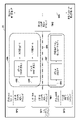
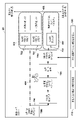
- FIG. 1 is a diagram showing a configuration example of the information generation system STM.
- the information generation system SYM includes a management server 10 that manages customer debt repayment information and credit information, and a portable information processing device such as a smartphone owned by the customer.
- a terminal hereinafter referred to as a terminal device 20
- FIG. 1 a single example of the terminal device 20 is shown, but it is possible to connect the terminal devices 20 of a plurality of customers to the network NW without being limited to this example.
- the vehicle 30 is a vehicle purchased by a customer of the terminal device 20 with a loan.
- the vehicle 30 may be, for example, a straddle-type vehicle or a riding-type vehicle.
- a saddle-type vehicle refers to a type in which the driver straddles the vehicle body and rides on it, and its concept includes not only typical two-wheeled vehicles (including scooter-type vehicles), but also three-wheeled vehicles (one front wheel and two rear wheels, or Vehicles of various types, such as a vehicle with two front wheels and one rear wheel, are also included.
- the vehicle 30 has a control unit 31 and a communication unit 32 as a mechanical configuration.
- the control unit 31 is an ECU (electronic control unit) capable of controlling the operation of the entire vehicle 30.
- the control unit 31 receives a control signal received from the control server 40 via the network NW, and starts the vehicle 30. It is possible to control devices and drive mechanisms.
- the communication unit 32 includes a TCU (Telematics Control Unit) that performs signal processing for communicating with the control server 40 via the network NW.
- the TCU can acquire information indicating the control state of the vehicle 30 from the control unit 31, and transmits the acquired information to the control server 40 via the network NW. Further, the TCU can intervene in the vehicle control in the control unit 31 based on the information received from the control server 40, and can control the control unit 31 to limit the functions of the vehicle 30 or cancel the limitation. is.
- a control server 40 that remotely controls the vehicle 30 has a processing unit 41 , a storage unit 42 and a communication unit 43 .
- the processing unit 41 is composed of a processor including a CPU and a memory
- the storage unit 42 includes a RAM serving as a program processing area, a ROM storing various programs and data executed by the processing unit 41, and a relatively large-capacity memory. It is composed of an HDD (Hard Disk Drive).
- the communication unit 43 can mutually communicate with the communication unit 32 of the vehicle 30 and the communication unit 12 of the management server 10 via the network NW.
- the management server 10 is located in, for example, a financial institution or a credit bureau, and the management server 10 provides the customer with the use of the vehicle 30 while the customer is appropriately repaying the loan. is permitted, and if the customer's credit information falls below a predetermined level, such as when there is a predetermined number of consecutive delinquent payments on a predetermined repayment date, usage restrictions (function restrictions) can be determined. It is possible.
- the processing unit 11 of the management server 10 determines the function restriction
- the communication unit 12 of the management server 10 transmits information instructing usage restriction to the control server 40 .
- the processing unit 41 receives the function restriction instruction from the management server 10
- the processing unit 41 generates a signal (function restriction signal) requesting the function restriction of the vehicle 30 and transmits the signal to the vehicle 30 .
- the control unit 31 of the vehicle 30 controls the functions of the vehicle 30 to be restricted.
- the management server 10 releases the usage restriction (function restriction).
- the control server 40 receives an instruction to release the use restriction (function restriction) from the management server 10
- the processing unit 41 generates a signal requesting release of the function restriction of the vehicle 30 and transmits the signal to the vehicle 30 .
- the control unit 31 of the vehicle 30 controls the vehicle 30 to release the functional restriction.
- the management server 10 has a processing unit 11 (CPU), a communication unit 12, and a storage unit 13 as a hardware configuration.
- the processing unit 11 (CPU: Central Processing Unit) performs various processes for controlling the management server 10 as a whole.
- the communication unit 12 can transmit and receive data to and from the customer's terminal device 20 and the control server 40 via the network NW.
- the communication unit 12 transmits information generated by the processing unit 11 to the terminal device 20 .
- the storage unit 13 includes a ROM (Read Only Memory) for storing programs to be executed by the processing unit 11, and a RAM (Random Access Memory) for storing various information as a work area when the processing unit 11 executes the programs. Memory).
- the storage unit 13 also has a large-capacity storage unit (hereinafter referred to as a customer information storage unit 130) that stores customer debt repayment information.
- the storage unit 13 can be configured by a memory card, flash memory, HDD (Hard Disk Drive), or the like.
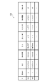
- FIG. 2 is a diagram showing a configuration example of the customer information storage unit 130.
- the debt repayment information stored in the customer information storage unit 130 includes an ID (identification information) for identifying a customer, a customer name, a loan amount, Repayment period, monthly payment due date, set payment amount (set amount), income information, customer repayment history (for example, customer A: 1st payment ( ⁇ ), 2nd payment ( ⁇ ), customer B 1st time: non-payment (x), 2nd time: payment (o)), (cumulative evaluation value) based on payment performance, credit information, etc. are included.
- the income information is the customer's income input from the input unit 24 of the terminal device 20 in response to the customer's input operation. amount).
- the (accumulated evaluation value) based on the payment record in the customer information storage unit 130 is the first evaluation level for the planned route (for example, the planned route 404 in FIG. 9) in the most recent repayment state, or the planned route 404 is evaluation information indicating the low second evaluation.
- the processing unit 11 has an information generation display unit 110 as a functional configuration.
- the information generation display unit 110 generates simulation information based on predetermined debt repayment information including at least the borrowing amount and the repayment period that are the target of debt repayment of the customer, and displays it on a predetermined display unit (for example, the customer's terminal device 20 The simulation information is displayed on the display unit 25).
- the functional configuration of the information generation display unit 110 is realized by executing a predetermined program read from the storage unit 13 by the processing unit 11 of the management server 10 .
- the configuration of the information generating and displaying unit 110 may be configured by an integrated circuit or the like, as long as they perform similar functions.
- the terminal device 20 includes a processing section 21 , a storage section 22 , a communication section 23 , an input section 24 and a display section 25 .
- the processing unit 21 (CPU: control unit) performs various processes in the terminal device 20 .
- the storage unit 22 has a ROM for storing programs to be executed by the processing unit 21 and a RAM for storing various information as a working area when the processing unit 21 executes the programs.
- the storage unit 22 also has a storage unit that stores various information received from the management server 10 .
- the communication unit 23 can bi-directionally communicate with the management server 10 via the network NW.
- the input unit 24 receives various inputs from the customer.
- the input unit 24 is, for example, a touch panel.
- the display unit 25 displays various information.
- the display unit 25 is configured as a display capable of displaying simulation information generated by the information generation display unit 110 of the management server 10 .
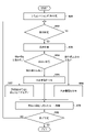
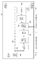
- FIG. 3 is a diagram for explaining the flow of information processing in the information generation system STM.
- the information generation display unit 110 of the management server 10 generates simulation information for achieving the customer's debt repayment target.
- the information generation display unit 110 refers to the information stored in the customer information storage unit 130 to determine the due date.
- the information generating and displaying unit 110 determines whether it is the due date of debt repayment or a predetermined timing before the due date. If the date information in the customer's debt repayment schedule has not reached the predetermined timing (S32-No), the information generation display unit 110 waits until the predetermined timing is reached. On the other hand, if it is determined in S32 that the date information in the debt repayment schedule has reached the payment date or a predetermined timing prior to the payment date (S32-Yes), the information generating and displaying unit 110 advances the process to S33.
- the information generation display unit 110 transmits the generated simulation information to the customer's terminal device 20 via the network NW, and performs display control to display the simulation information on the display unit 25 of the terminal device 20.
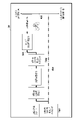
- FIG. 4 is a diagram illustrating a display screen of the display unit 25 of the terminal device 20.
- the information generation display unit 110 selects one of a plurality of start points (SP1, SP2, SP3) according to the customer's starting payment amount (payment amount) or the customer's credit information acquired from the customer information storage unit 130.
- SP1 start point
- SP2 start point
- One start point (SP1) selected from is set as the display start position of the simulation information, and the actual route and the planned route in the simulation information are displayed on the display unit 25 with the display start position as the starting point.
- the customer's monthly income and monthly payment amount are set differently at a plurality of start points (SP1, SP2, SP3).
- the information generating and displaying unit 110 can display an icon that schematically shows the vehicle and the occupants together with the simulation information on the display unit 25 in order to clearly indicate the payment start point or the customer's payment status.
- an icon is displayed at the position of the start point SP1, and by visually recognizing the icon, it is possible to easily confirm that the simulation information is displayed from the start point SP1.
- an icon is displayed at a position that clearly indicates the customer's payment status, and the customer can easily check his/her own payment status by visually recognizing the icon.
- a start point SP1 is set, and a planned route 404 showing the customer's payment plan is displayed with the start point SP1 as the starting point.
- TM1 indicates the due date of the first payment in planned route 404 and TM2 indicates the due date of the second payment.
- the display example of FIG. 4 shows a case where the preset amount (repayment amount) is 1000 yen.
- the information generating and displaying unit 110 generates a preset set amount (for example, 1000 yen) or more than the set amount (for example, 5000 yen) on the payment date (TM1 in FIG. 4) or before the payment date for debt repayment. and a second evaluation lower than the first evaluation ( 407) is displayed on the display unit 25.
- a preset set amount for example, 1000 yen
- the set amount for example, 5000 yen
- the high evaluation value and the low evaluation value are predetermined evaluation values for the payment.
- a high evaluation value is stipulated. In this way, by giving a high evaluation value according to the payment record as an advantageous evaluation given by paying a predetermined repayment amount, it is possible to arouse motivation for payment.
- an advantageous evaluation (first evaluation (406) given by paying a predetermined repayment amount and a disadvantageous evaluation (1st evaluation (406)) given when the predetermined repayment amount is not paid are displayed.
- a rating (second rating (407)) can be displayed.
- the horizontal axis direction along the planned route 404 indicates the time axis in the simulation information
- the direction of the vertical axis 405 intersecting the planned route 404 indicates the evaluation level reflecting the customer's payment record. indicates If you fulfill the obligation to repay the loan, the evaluation will be high, and if you neglect the repayment obligation, the evaluation will be low.
- the display position of the display unit 25 is based on the simulation information display start position (SP1). Indicates low. When 5000 yen is paid on the due date and when 1000 yen is paid, the level of the first evaluation differs. becomes higher.
- the information generation display unit 110 determines the customer's payment in S34.
- the information generation display unit 110 gives the customer a small evaluation value (S35).
- the information generating and displaying unit 110 gives the customer a high evaluation value (S36).
- the information generation display unit 110 gives no evaluation value or gives a penalty to the customer (S37).
- the boundary between the first evaluation and the second evaluation is distinguished by whether or not an evaluation value is given, but the present invention is not limited to this example.
- the S37 "no evaluation value is given” is executed with the processing on the S35 side as "a small evaluation value or no evaluation value is given", and the S37 side It is also possible to execute the processing of as a "penalty”.
- the penalty is relative to the evaluation value assignment, and if the evaluation value assignment is given as points, the penalty means subtraction of the assigned points. Note that the content of the penalty is not limited to this, and it is sufficient if there is a difference so that the boundary between the first evaluation and the second evaluation (distinction between the processes of S35 and S37) can be clearly distinguished.
- the information generation display unit 110 performs route update processing according to the customer's payment record in S35 to S37.
- a first branch route (branch routes 401, 402 ) and a second branching route (branching route 403 ) showing a second evaluation 407 .
- the information generation display unit 110 updates the display of the record route indicating the customer's payment record and the display of the plurality of branch routes according to the customer's payment record. For example, when the set amount (1,000 yen) is paid on the payment date TM1, the information generation/display unit 110 advances the track record route indicating the customer's payment track record to the branch route 401 .
- FIG. 5 is a diagram showing a display example of the route update according to the payment record (1000 yen payment) on the due date TM1. is shown.
- the information generation display unit 110 erases the branch route 402 and the branch route 403 that were displayed in FIG. do.
- a record route 504 indicating the customer's payment record is advanced on the branch route 401 shown in FIG. That is, the display of the branch route 401 is updated as the actual route 504 .
- the information generation display unit 110 makes an end determination regarding the display of the simulation information.
- the information generation display unit 110 refers to the customer information storage unit 130, and if the next payment due date is not set (S39-Yes), the process ends. On the other hand, if the next payment due date is set in S39 (S39-No), the information generation display unit 110 returns the process to S32 and repeats the same process.
- the information generation display unit 110 refers to the information stored in the customer information storage unit 130 to determine the due date. If it is determined in S32 that the date information in the debt repayment schedule has reached the payment date or a predetermined timing prior to the payment date (S32-Yes), the information generating and displaying unit 110 advances the process to S33.
- the information generation display unit 110 performs the first evaluation (406) and the first evaluation (406) at the payment date (TM2 in FIG. 5) or at a stage before the payment date for debt repayment, similarly to the display control described with reference to FIG. 2 evaluation (407) is displayed on the display unit 25 of the customer's terminal device 20 to motivate the customer to pay. That is, the information generating and displaying unit 110 generates a preset set amount (for example, 1000 yen) or more than the set amount (for example, 5000 yen) at the payment date (TM2 in FIG. 5) or at a stage before the payment date for debt repayment. yen), and the second evaluation, which is lower than the first evaluation, is given to the customer when the preset amount (1000 yen) cannot be paid. Evaluation (407) is displayed on the display unit 25.
- a preset set amount for example, 1000 yen
- the set amount for example, 5000 yen
- Evaluation (407) is displayed on the display unit 25.
- the display positions of the first evaluation and the second evaluation in Fig. 5 are highly evaluated due to the performance of paying the set amount (1000 yen) on the previous payment date. That is, the information generation display unit 110 changes the display positions of the actual route 504 and the plurality of branch routes (501, 502, 503) in the screen of the display unit 25 to the customer's first evaluation based on the customer's payment performance and It changes according to the accumulation of the second evaluation.
- the accumulation of the negative portion of the second evaluation is zero, and it is based on the accumulation of the first evaluation that has a payment record. display has been changed. In this way, by changing the display position based on the payment performance, it is possible to easily visually recognize the degree of achievement of the customer's debt repayment target based on the level of the first evaluation added based on the payment performance. becomes possible.
- FIG. 6 is a diagram showing a display example of the route update according to the payment record (payment of 5000 yen) on the due date TM2, and shows the case where the customer paid 5000 yen on the due date TM2.
- FIG. 6 shows the repayment status after the next day (March 5) of the due date TM2 on which the actual payment is reflected.
- the information generation display unit 110 erases the branch route 501 and the branch route 503 displayed in FIG. do.
- a record route 504 indicating the customer's payment record is advanced on the branch route 502 shown in FIG. That is, the display of the branch route 502 is updated as the actual route 504 .
- the information generation display unit 110 shifts the display position of the actual route 504 upward (in the direction in which the first evaluation becomes higher) by the amount of the large evaluation value given by the payment on the due date TM2. to display.
- the customer can update the degree of achievement of the customer's debt repayment target to a higher level based on the level of the first evaluation displayed on the display unit 25 of the terminal device 20, which is added based on the payment record. It becomes possible to easily visually recognize what has been done.
- the information generation display unit 110 determines whether the display of the simulation information is finished. If the next payment date is set (S39-No), the information generation display unit 110 continues processing Returning to S32, the same processing is sequentially repeated.
- FIG. 7 is a diagram showing a display example of the route update according to the record of delinquencies where the set amount (1000 yen) could not be paid on the due date TM1. It shows the repayment status after that.
- the information generation display unit 110 advances the display of the actual result route 704 to the second branch route (branch route 403 in FIG. 4).
- the information generation display unit 110 erases the branch route 401 and the branch route 402 displayed in FIG. do.
- a track record route 704 indicating the customer's track record of delinquency proceeds on the branch route 403 shown in FIG. That is, the display of the branch route 403 is updated as the actual route 704 .
- the information generating and displaying unit 110 causes the display unit 25 to display a rescue route 705 for paying the set amount from the actual route 704 .
- the information generating and displaying unit 110 generates a first branch route (branch routes 701 and 702) indicating the first evaluation and a second branch indicating the second evaluation, with the payment due date TM2 next to the debt repayment in the relief route 705 as a branch point.
- the route (branch route 703) is displayed on the display unit 25.
- the information generating and displaying unit 110 is defined in advance for payment when the set amount or more is paid on the next payment date TM2 or before the next payment date.
- the display unit 25 displays that evaluation values (small evaluation value+ ⁇ 1, large evaluation value+ ⁇ 2) higher than the evaluation values (small evaluation value, large evaluation value) are to be given.
- ⁇ 1 and ⁇ 2 are the additional evaluation values given to the payment in the relief route 705.
- the additional evaluation value ⁇ 2 when paying 5000 yen is the additional evaluation value ⁇ 1 when paying 1000 yen.
- the information generating and displaying unit 110 causes the display unit 25 (sub-screen 26 of the display unit 25) to display a plurality of candidate causes that may hinder payment when the set amount is not paid by the payment date, and allows the customer to input. Based on this, the cause of failure to pay the set amount is specified, and a solution for solving the specified cause is presented on the display unit.
- the information generating and displaying unit 110 displays a display for specifying a cause candidate that may hinder payment when the set amount is not paid by the payment due date (710 in FIG. 7, ST101 in FIG. 10), and displays the specified cause.
- a display (720 in FIG. 7, ST102 in FIG. 10) presenting a solution for solving the problem is displayed on the sub-screen 26 of the display section 25 of the terminal device 20.
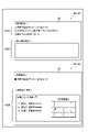
- FIG. 10 is a diagram exemplifying the sub-screen 26 on the display unit 25 of the terminal device 20.
- FIG. ST101 of FIG. 10 is a diagram showing a state in which a plurality of candidate causes 1010 that may hinder payment are displayed.
- the cause candidates are not limited to these examples, and any cause candidate can be displayed.
- the solution display example 1020 is blank. The customer can select one of the plurality of cause candidates by operating the input unit 24 of the terminal device 20 .
- ST102 of FIG. 10 shows an example 1020 of solution presentation when the customer selects the item "cannot work due to hospital or injury" as the cause of ST101.
- the system presents a list of affiliated hospitals (names of hospitals A, B, and C, contact information for each hospital) and map information for guiding to each hospital.
- presentation of solutions is not limited to this example, and arbitrary solutions can be displayed.
- the information generation display is performed only when the proof based on the diagnostic information is input from the terminal device 20.
- the unit 110 can also adjust the simulation information, such as extending the next payment due date TM2 in the relief route 705 or reducing the payment amount.
- FIG. 8 is a diagram showing a display example of route update according to the payment performance (1000 yen payment) on the due date TM2 in the relief route 705, and shows a case where the customer paid 1000 yen on the due date TM2. .
- FIG. 8 shows the repayment status after the next day (March 5) of the due date TM2 on which the actual payment is reflected.
- the information generation display unit 110 erases the branch route 702 and the branch route 703 that were displayed in FIG. do.
- the display of the branch route 701 shown in FIG. 7 is updated as the actual route 804 .
- the information generation display unit 110 shifts the display position of the actual route 804 above the display unit 25 (the first evaluation is direction).
- the customer can update the degree of achievement of the customer's debt repayment target to a higher level based on the level of the first evaluation displayed on the display unit 25 of the terminal device 20, which is added based on the payment record. It becomes possible to easily visually recognize what has been done.
- information generation display The unit 110 adds additional evaluation values ( ⁇ 1, ⁇ 2) to predetermined prescribed values (low evaluation value, high evaluation value) based on the payment record in the relief route 705 . This makes it possible to arouse motivation for payment.
- the information generation display unit 110 stops generating and displaying the relief route 705 .
- the information generating and displaying unit 110 as described in FIG. Display control is performed to display a two-branched route (branched route 403). Assignment of the evaluation value to the payment is returned to the predetermined evaluation value (low evaluation value, high evaluation value) for the payment.
- the subsequent display control of the simulation information is the same as that described above with reference to FIGS. 4 to 6.
- FIG. 9 is a diagram schematically showing an overall display of the planned route 404, the actual route 704, and the relief route 705 displayed on the display unit 25 of the terminal device 20 by the information generation display unit 110.
- FIG. ST91 in FIG. 9 shows a state in which the planned route 404 is restored by repayment using the relief route 705 when the customer's evaluation is lowered to the second evaluation side.
- the generation and display of the relief route 705 is possible even when the customer's evaluation falls to the second evaluation side.
- the information generation and display unit 110 can generate relief routes 705a, 705b, and 705c at the timing of confirming a predetermined branch route and display them on the display unit 25.
- FIG. As a result, even if the customer's evaluation is lowered to the second evaluation side, the customer can return the evaluation to the first evaluation side by performing repayment using the remedy routes 705a, 705b, 705c, etc. Customers with declining ratings can be encouraged and motivated to pay.
- ST92 in FIG. 9 is a diagram showing a state in which the customer has paid a preset set amount or more than the set amount at or before the payment due date for debt repayment.
- the customer's evaluation is displayed shifted upward (in the direction in which the first evaluation becomes higher) on the display section 25 .
- Weight information is set for each of the planned route 404, the first branch route (for example, the branch routes 401 and 402 in FIG. 4), and the second branch route (for example, the branch route 403 in FIG. 4).
- 110 shows the actual route traced from the display start position (SP1) to the most recent repayment state, including the planned route 404, the first branch route (for example, the branch routes 401 and 402 in FIG.
- the route history is stored in the customer information storage unit 130 as the customer's repayment history. Added weight information obtained by adding information can be obtained.
- the information generation display unit 110 acquires evaluation information indicating the high first evaluation for the planned route 404 or the low second evaluation for the planned route 404 in the most recent repayment state. Then, the information generating and displaying unit 110 generates credit information of the customer in the most recent repayment state based on at least one of the addition weight information and the evaluation information. In this way, since the customer's repayment attitude toward each repayment is reflected in the credit information, it is possible to arouse motivation for payment. Furthermore, in conjunction with the high level of credit information, it is possible to acquire the right to use low-interest loans, expand credit lines, and obtain opportunities such as better job introductions, thereby increasing the payment It becomes possible to further arouse motivation.
- the present invention supplies a program that realizes the functions of the above-described embodiments to an information generation system or a device that constitutes the information generation system via a network or a storage medium, and one or more processors in the computer of the information generation system. can read the program and execute the processing of the information generation system.
- STM information generation system
- 10 management server
- 11 processing unit
- 12 communication unit
- 13 storage unit
- 20 terminal device
- 25 display unit
- 110 information generation display unit
- 130 customer information storage unit
Landscapes
- Business, Economics & Management (AREA)
- Accounting & Taxation (AREA)
- Finance (AREA)
- Engineering & Computer Science (AREA)
- Development Economics (AREA)
- Economics (AREA)
- Marketing (AREA)
- Strategic Management (AREA)
- Technology Law (AREA)
- Physics & Mathematics (AREA)
- General Business, Economics & Management (AREA)
- General Physics & Mathematics (AREA)
- Theoretical Computer Science (AREA)
- Financial Or Insurance-Related Operations Such As Payment And Settlement (AREA)
Abstract
Description
債務返済の目標となる借入金額及び返済期間を少なくとも含む所定の債務返済情報に基づいてシミュレーション情報を生成し、所定の表示手段(25)に前記シミュレーション情報を表示させる情報生成表示手段(110)を備え、
前記情報生成表示手段(110)は、
前記債務返済の支払い期日もしくは前記支払い期日よりも前の段階で、予め設定された設定額もしくは前記設定額以上に支払えた場合に前記顧客に付与される第1評価(406)と、予め設定された前記設定額を支払えなかった場合に前記顧客に付与される、前記第1評価よりも低い第2評価(407)と、を前記表示手段(25)に表示させる。
前記顧客の支払い実績を示す実績ルート(504)と、
前記顧客の支払い計画を示す計画ルート(404)と、
前記債務返済の支払い期日を分岐点に、前記計画ルート、若しくは前記実績ルートから分岐した複数の分岐ルートとして、前記第1評価を示す第1分岐ルート(501、502)と、前記第2評価を示す第2分岐ルート(503)と、を前記表示手段(25)に表示させ、
前記支払い実績に応じて前記実績ルートと、前記複数の分岐ルートとの表示を更新する。
前記表示手段(25)の前記表示位置は、前記シミュレーション情報の表示開始の位置を基準として、前記画面の一方側を前記第1評価の高さを示し、前記一方側とは逆向きの他方側を前記第2評価の低さを示す。
前記表示開始の位置を起点として、前記実績ルートと前記計画ルートとを前記表示手段(25)に表示させる。
前記支払い期日までに前記設定額が支払えなかった場合に、前記実績ルートの表示を前記第2分岐ルートに進め、
前記実績ルートの表示を前記第2分岐ルートに進めた後に、当該実績ルートから前記設定額を支払うための救済ルート(705)を前記表示手段(25)に表示させる。
支払いの障害となり得る複数の原因候補(1010)を前記表示手段(25)に表示させ、
前記顧客からの入力に基づいて前記設定額が支払えなかった原因を特定し、
前記特定された原因を解決する解決策(1020)を前記表示手段(25)に提示する。
前記情報生成表示手段(110)は、前記顧客の収入に応じて前記設定額を決定する。
前記救済ルートにおける次の支払い期日を分岐点に、前記第1評価を示す第1分岐ルート(701、702)と、前記第2評価を示す第2分岐ルート(703)と、を前記表示手段(25)に表示させ、
前記次の支払い期日もしくは前記次の支払い期日よりも前の段階で、前記設定額もしくは前記設定額以上に支払えた場合に、支払いに対して予め規定されている評価値に比べて高い評価値(α1、α2)を付与することを前記表示手段(25)に表示させる。
前記情報生成表示手段(110)は、
前記表示開始の位置から直近の返済状態まで辿ってきた前記実績ルートが、前記計画ルート、前記第1分岐ルート、及び前記第2分岐ルートのうちから経由したルートの履歴により前記重み情報を加算した加算重み情報を取得し、
前記直近の返済状態における、前記計画ルートに対する前記第1評価の高さ、もしくは前記計画ルートに対する前記第2評価の低さを示す評価情報を取得し、
前記加算重み情報および前記評価情報のうち少なくともいずれか一方に基づいて、前記直近の返済状態における前記顧客の与信情報を生成する。
債務返済の目標となる借入金額及び返済期間を少なくとも含む所定の債務返済情報に基づいてシミュレーション情報を生成し、所定の表示手段(25)に前記シミュレーション情報を表示させる情報生成表示工程(S31~S33)有し、
前記情報生成表示工程(S31~S33)では、
前記債務返済の支払い期日もしくは前記支払い期日よりも前の段階で、予め設定された設定額もしくは前記設定額以上に支払えた場合に前記顧客に付与される第1評価(406)と、予め設定された前記設定額を支払えなかった場合に前記顧客に付与される、前記第1評価よりも低い第2評価(407)と、を前記表示手段(25)に表示させる。
債務返済の目標となる借入金額及び返済期間を少なくとも含む所定の債務返済情報に基づいてシミュレーション情報を生成し、所定の表示手段(25)に前記シミュレーション情報を表示させる情報生成表示工程(S31~S33)有し、
前記情報生成表示工程(S31~S33)では、
前記債務返済の支払い期日もしくは前記支払い期日よりも前の段階で、予め設定された設定額もしくは前記設定額以上に支払えた場合に前記顧客に付与される第1評価(406)と、予め設定された前記設定額を支払えなかった場合に前記顧客に付与される、前記第1評価よりも低い第2評価(407)と、を前記表示手段(25)に表示させる。
管理サーバ10は、ハードウェア構成として、処理部11(CPU)、通信部12、記憶部13を有する。処理部11(CPU:Central Processing Unit)は、管理サーバ10の全体を制御するための各種の処理を行う。
端末装置20は、処理部21と、記憶部22と、通信部23と、入力部24と、表示部25とを含む。処理部21(CPU:制御部)は、端末装置20における各種の処理を行う。記憶部22は、処理部21で実行されるプログラムを記憶するためのROMと、処理部21がプログラムを実行する際の作業領域として各種情報を記憶するためのRAMとを有する。また、記憶部22は、管理サーバ10から受信した各種情報を記憶する記憶部を有する。
図3は情報生成システムSTMにおける情報処理の流れを説明する図である。S31において、管理サーバ10の情報生成表示部110は顧客の債務返済目標を達成するためのシミュレーション情報を生成する。
本発明は、上述の実施形態の機能を実現するプログラムを、ネットワーク又は記憶媒体を介して情報生成システムまたは情報生成システムを構成する装置に供給し、その情報生成システムのコンピュータにおける1つ以上のプロセッサがプログラムを読出して、情報生成システムの処理を実行することも可能である。
12:通信部、13:記憶部、20:端末装置、25:表示部、
110:情報生成表示部、130:顧客情報記憶部
Claims (11)
- 顧客の債務返済目標を達成するためのシミュレーション情報を生成する情報生成システム(STM)であって、
債務返済の目標となる借入金額及び返済期間を少なくとも含む所定の債務返済情報に基づいてシミュレーション情報を生成し、所定の表示手段(25)に前記シミュレーション情報を表示させる情報生成表示手段(110)を備え、
前記情報生成表示手段(110)は、
前記債務返済の支払い期日もしくは前記支払い期日よりも前の段階で、予め設定された設定額もしくは前記設定額以上に支払えた場合に前記顧客に付与される第1評価(406)と、予め設定された前記設定額を支払えなかった場合に前記顧客に付与される、前記第1評価よりも低い第2評価(407)と、を前記表示手段(25)に表示させることを特徴とする情報生成システム。 - 前記情報生成表示手段(110)は、前記シミュレーション情報として、
前記顧客の支払い実績を示す実績ルート(504)と、
前記顧客の支払い計画を示す計画ルート(404)と、
前記債務返済の支払い期日を分岐点に、前記計画ルート、若しくは前記実績ルートから分岐した複数の分岐ルートとして、前記第1評価を示す第1分岐ルート(501、502)と、前記第2評価を示す第2分岐ルート(503)と、を前記表示手段(25)に表示させ、
前記支払い実績に応じて前記実績ルートと、前記複数の分岐ルートとの表示を更新する
ことを特徴とする請求項1に記載の情報生成システム。 - 前記情報生成表示手段(110)は、前記表示手段(25)の画面内における前記実績ルートと前記複数の分岐ルートとの表示位置を、前記顧客の支払い実績に基づいた前記顧客の前記第1評価および前記第2評価の累積に応じて変更し、
前記表示手段(25)の前記表示位置は、前記シミュレーション情報の表示開始の位置を基準として、前記画面の一方側を前記第1評価の高さを示し、前記一方側とは逆向きの他方側を前記第2評価の低さを示す
ことを特徴とする請求項2に記載の情報生成システム。 - 前記情報生成表示手段(110)は、記憶手段(130)から取得した前記顧客の支払い開始額もしくは前記顧客の与信情報に応じて、複数のスタート地点(SP1、SP2、SP3)の中から選択された一つのスタート地点(SP1)を、前記シミュレーション情報の前記表示開始の位置として設定し、
前記表示開始の位置を起点として、前記実績ルートと前記計画ルートとを前記表示手段(25)に表示させることを特徴とする請求項3に記載の情報生成システム。 - 前記情報生成表示手段(110)は、
前記支払い期日までに前記設定額が支払えなかった場合に、前記実績ルートの表示を前記第2分岐ルートに進め、
前記実績ルートの表示を前記第2分岐ルートに進めた後に、当該実績ルートから前記設定額を支払うための救済ルート(705)を前記表示手段(25)に表示させることを特徴とする請求項2乃至4のいずれか1項に記載の情報生成システム。 - 前記情報生成表示手段(110)は、前記支払い期日までに前記設定額が支払えなかった場合に、
支払いの障害となり得る複数の原因候補(1010)を前記表示手段(25)に表示させ、
前記顧客からの入力に基づいて前記設定額が支払えなかった原因を特定し、
前記特定された原因を解決する解決策(1020)を前記表示手段(25)に提示することを特徴とする請求項5に記載の情報生成システム。 - 前記債務返済情報は前記顧客からの入力操作に応じて入力された前記顧客の収入を含み、
前記情報生成表示手段(110)は、
前記顧客の収入に応じて前記設定額を決定することを特徴とする請求項1乃至6のいずれか1項に記載の情報生成システム。 - 前記情報生成表示手段(110)は、
前記救済ルートにおける次の支払い期日を分岐点に、前記第1評価を示す第1分岐ルート(701、702)と、前記第2評価を示す第2分岐ルート(703)と、を前記表示手段(25)に表示させ、
前記次の支払い期日もしくは前記次の支払い期日よりも前の段階で、前記設定額もしくは前記設定額以上に支払えた場合に、支払いに対して予め規定されている評価値に比べて高い評価値(α1、α2)を付与することを前記表示手段(25)に表示させることを特徴とする請求項5または6に記載の情報生成システム。 - 前記計画ルート、前記第1分岐ルート、前記第2分岐ルートにはそれぞれ重み情報が設定されており、
前記情報生成表示手段(110)は、
前記表示開始の位置から直近の返済状態まで辿ってきた前記実績ルートが、前記計画ルート、前記第1分岐ルート、及び前記第2分岐ルートのうちから経由したルートの履歴により前記重み情報を加算した加算重み情報を取得し、
前記直近の返済状態における、前記計画ルートに対する前記第1評価の高さ、もしくは前記計画ルートに対する前記第2評価の低さを示す評価情報を取得し、
前記加算重み情報および前記評価情報のうち少なくともいずれか一方に基づいて、前記直近の返済状態における前記顧客の与信情報を生成することを特徴する請求項3に記載の情報生成システム。 - 顧客の債務返済目標を達成するためのシミュレーション情報を生成する情報生成システム(STM)における情報処理方法であって、
債務返済の目標となる借入金額及び返済期間を少なくとも含む所定の債務返済情報に基づいてシミュレーション情報を生成し、所定の表示手段(25)に前記シミュレーション情報を表示させる情報生成表示工程(S31~S33)有し、
前記情報生成表示工程(S31~S33)では、
前記債務返済の支払い期日もしくは前記支払い期日よりも前の段階で、予め設定された設定額もしくは前記設定額以上に支払えた場合に前記顧客に付与される第1評価(406)と、予め設定された前記設定額を支払えなかった場合に前記顧客に付与される、前記第1評価よりも低い第2評価(407)と、を前記表示手段(25)に表示させることを特徴とする情報処理方法。 - 顧客の債務返済目標を達成するためのシミュレーション情報を生成する情報生成システム(STM)における情報処理方法をコンピュータに実行させるプログラムであって、前記情報処理方法が、
債務返済の目標となる借入金額及び返済期間を少なくとも含む所定の債務返済情報に基づいてシミュレーション情報を生成し、所定の表示手段(25)に前記シミュレーション情報を表示させる情報生成表示工程(S31~S33)有し、
前記情報生成表示工程(S31~S33)では、
前記債務返済の支払い期日もしくは前記支払い期日よりも前の段階で、予め設定された設定額もしくは前記設定額以上に支払えた場合に前記顧客に付与される第1評価(406)と、予め設定された前記設定額を支払えなかった場合に前記顧客に付与される、前記第1評価よりも低い第2評価(407)と、を前記表示手段(25)に表示させることを特徴とするプログラム。
Priority Applications (2)
| Application Number | Priority Date | Filing Date | Title |
|---|---|---|---|
| JP2023510043A JP7524464B2 (ja) | 2021-03-31 | 2021-03-31 | 情報生成システム、情報生成システムにおける情報処理方法及びプログラム |
| PCT/JP2021/013890 WO2022208752A1 (ja) | 2021-03-31 | 2021-03-31 | 情報生成システム、情報生成システムにおける情報処理方法及びプログラム |
Applications Claiming Priority (1)
| Application Number | Priority Date | Filing Date | Title |
|---|---|---|---|
| PCT/JP2021/013890 WO2022208752A1 (ja) | 2021-03-31 | 2021-03-31 | 情報生成システム、情報生成システムにおける情報処理方法及びプログラム |
Publications (1)
| Publication Number | Publication Date |
|---|---|
| WO2022208752A1 true WO2022208752A1 (ja) | 2022-10-06 |
Family
ID=83458175
Family Applications (1)
| Application Number | Title | Priority Date | Filing Date |
|---|---|---|---|
| PCT/JP2021/013890 Ceased WO2022208752A1 (ja) | 2021-03-31 | 2021-03-31 | 情報生成システム、情報生成システムにおける情報処理方法及びプログラム |
Country Status (2)
| Country | Link |
|---|---|
| JP (1) | JP7524464B2 (ja) |
| WO (1) | WO2022208752A1 (ja) |
Citations (3)
| Publication number | Priority date | Publication date | Assignee | Title |
|---|---|---|---|---|
| JP2004139620A (ja) * | 2003-12-19 | 2004-05-13 | Takahashi Hiroshi | 購入情報処理機構 |
| JP2016206783A (ja) * | 2015-04-17 | 2016-12-08 | アルヒ株式会社 | 情報提供方法及び情報提供装置 |
| JP2017188111A (ja) * | 2016-04-05 | 2017-10-12 | 株式会社野村総合研究所 | 資産運用・債務返済シミュレーション生成装置、プログラム及び方法 |
-
2021
- 2021-03-31 WO PCT/JP2021/013890 patent/WO2022208752A1/ja not_active Ceased
- 2021-03-31 JP JP2023510043A patent/JP7524464B2/ja active Active
Patent Citations (3)
| Publication number | Priority date | Publication date | Assignee | Title |
|---|---|---|---|---|
| JP2004139620A (ja) * | 2003-12-19 | 2004-05-13 | Takahashi Hiroshi | 購入情報処理機構 |
| JP2016206783A (ja) * | 2015-04-17 | 2016-12-08 | アルヒ株式会社 | 情報提供方法及び情報提供装置 |
| JP2017188111A (ja) * | 2016-04-05 | 2017-10-12 | 株式会社野村総合研究所 | 資産運用・債務返済シミュレーション生成装置、プログラム及び方法 |
Also Published As
| Publication number | Publication date |
|---|---|
| JPWO2022208752A1 (ja) | 2022-10-06 |
| JP7524464B2 (ja) | 2024-07-29 |
Similar Documents
| Publication | Publication Date | Title |
|---|---|---|
| Frei | The four things a service business must get right | |
| JP7280320B2 (ja) | 資産運用・債務返済シミュレーション生成装置、プログラム及び方法 | |
| Kling et al. | Computing as social action: The social dynamics of computing in complex organizations | |
| Koh | Personal financial planning | |
| JP2003521020A (ja) | インストルメントのポートフォリオの規則に基づいた展開を提供するリスク管理のシステムおよび方法 | |
| US8447633B2 (en) | Methods and systems for providing vehicle insurance | |
| JPWO2017221448A1 (ja) | 情報処理装置、情報処理方法およびプログラム | |
| JP6961042B2 (ja) | 目標達成ポートフォリオ生成装置、プログラム及び方法 | |
| JP5592683B2 (ja) | 生活設計支援プログラム | |
| WO2022208752A1 (ja) | 情報生成システム、情報生成システムにおける情報処理方法及びプログラム | |
| JP2004295492A (ja) | ライフプランニング装置および方法、コンピュータプログラム、プログラム記録媒体 | |
| US20080021768A1 (en) | Method and system for improved project delivery | |
| Mukherjea et al. | Coffee Can Investing: the low risk road to stupendous wealth | |
| JP4607557B2 (ja) | アカウント型保険管理システム、管理方法、および、アカウント型保険管理プログラム | |
| US20120197777A1 (en) | Online System and Method for Issuing Collateralized Securities | |
| KR102929893B1 (ko) | 블록체인 기술을 이용한 회사 지분과 채권 거래 플랫폼 구축 방법과 그 시스템 | |
| Schumann et al. | System of Negotiations: Game Theory and Behavioral Economics in Procurement–the Guide for Professionals | |
| JPWO2022208752A5 (ja) | ||
| JP6133158B2 (ja) | 担保物件任意売却管理プログラムおよび担保物件任意売却管理システム | |
| Adendorff | A best practice model for international Financial feasibility in property Development | |
| Katiti | Factors of Production, County Government Policies and Financial Growth of Commercial Real Estate Investment in Machakos County, Kenya | |
| CN119558908A (zh) | 机票优惠金额的确定方法、系统、电子设备和程序产品 | |
| Redling et al. | Personal Finance Workbook for Beginners: Practical Exercises for Smarter Money Management and Financial Empowerment | |
| Emerson | Fast-Track to Financial Freedom: The 10-Year Blueprint | |
| Duarte | Options Trading for Dummies |
Legal Events
| Date | Code | Title | Description |
|---|---|---|---|
| 121 | Ep: the epo has been informed by wipo that ep was designated in this application |
Ref document number: 21934918 Country of ref document: EP Kind code of ref document: A1 |
|
| WWE | Wipo information: entry into national phase |
Ref document number: 2023510043 Country of ref document: JP |
|
| WWE | Wipo information: entry into national phase |
Ref document number: 202317066455 Country of ref document: IN |
|
| NENP | Non-entry into the national phase |
Ref country code: DE |
|
| 122 | Ep: pct application non-entry in european phase |
Ref document number: 21934918 Country of ref document: EP Kind code of ref document: A1 |