WO2022202835A1 - 通信制御方法 - Google Patents
通信制御方法 Download PDFInfo
- Publication number
- WO2022202835A1 WO2022202835A1 PCT/JP2022/013269 JP2022013269W WO2022202835A1 WO 2022202835 A1 WO2022202835 A1 WO 2022202835A1 JP 2022013269 W JP2022013269 W JP 2022013269W WO 2022202835 A1 WO2022202835 A1 WO 2022202835A1
- Authority
- WO
- WIPO (PCT)
- Prior art keywords
- node
- trigger type
- iab
- relay node
- preemptive
- Prior art date
- Legal status (The legal status is an assumption and is not a legal conclusion. Google has not performed a legal analysis and makes no representation as to the accuracy of the status listed.)
- Ceased
Links
Images








Classifications
-
- H—ELECTRICITY
- H04—ELECTRIC COMMUNICATION TECHNIQUE
- H04W—WIRELESS COMMUNICATION NETWORKS
- H04W28/00—Network traffic management; Network resource management
- H04W28/02—Traffic management, e.g. flow control or congestion control
- H04W28/0278—Traffic management, e.g. flow control or congestion control using buffer status reports
-
- H—ELECTRICITY
- H04—ELECTRIC COMMUNICATION TECHNIQUE
- H04W—WIRELESS COMMUNICATION NETWORKS
- H04W72/00—Local resource management
- H04W72/04—Wireless resource allocation
-
- H—ELECTRICITY
- H04—ELECTRIC COMMUNICATION TECHNIQUE
- H04W—WIRELESS COMMUNICATION NETWORKS
- H04W72/00—Local resource management
- H04W72/12—Wireless traffic scheduling
Definitions
- the present disclosure relates to a communication control method used in a cellular communication system.
- IAB Integrated Access and Backhaul
- One or more relay nodes intervene in and relay for communication between the base station and the user equipment.
- a communication control method is a communication control method used in a cellular communication system.
- a donor base station having first and second relay nodes under its control sends a preemptive buffer status report (pre-emptive BSR ) trigger type.
- the communication control method includes the first relay node triggering the preemptive buffer status report to the second relay node according to the trigger type.
- a communication control method is a communication control method used in a cellular communication system.
- the communication control method includes a second relay node, which is a parent node of the first relay node, transmitting a trigger type of a preemptive buffer status report (pre-emptive BSR) to the first relay node.
- the communication control method includes the first relay node triggering the preemptive buffer status report to the second relay node according to the trigger type.
- a communication control method is a communication control method used in a cellular communication system.
- the communication control method includes a first relay node, which is a child node of a second relay node, transmitting a trigger type of a preemptive buffer status report (pre-emptive BSR) to the second relay node.
- the communication control method includes the first relay node triggering the preemptive buffer status report to the second relay node according to the trigger type.
- a communication control method is a communication control method used in a cellular communication system.
- a donor base station having a plurality of relay nodes under its control transmits a trigger type of a preemptive buffer status report (pre-emptive BSR) to a first relay node directly under the donor base station,
- a first relay node transmits the trigger type to a second relay node that is a child node of the first relay node, and repeats this for all relay nodes under the donor base station.
- the communication control method includes all relay nodes triggering the preemptive buffer status report according to the trigger type.
- FIG. 1 is a diagram showing a configuration example of a cellular communication system according to one embodiment.
- FIG. 2 is a diagram showing the relationship between IAB nodes, parent nodes, and child nodes.
- FIG. 3 is a diagram illustrating a configuration example of a gNB (base station) according to one embodiment.
- FIG. 4 is a diagram showing a configuration example of an IAB node (relay node) according to one embodiment.
- FIG. 5 is a diagram illustrating a configuration example of a UE (user equipment) according to one embodiment.
- FIG. 6 is a diagram showing an example of protocol stacks for IAB-MT RRC connection and NAS connection.
- FIG. 7 is a diagram representing an example protocol stack for the F1-U protocol.
- FIG. 8 is a diagram representing an example protocol stack for the F1-C protocol.
- FIG. 9 is a diagram showing a transmission example of preemptive BSR according to the first embodiment.
- FIG. 10 is a diagram showing a configuration example of the Pre-emptive BSR MAC CE according to the first embodiment.
- FIG. 11 is a diagram showing a setting example according to the first embodiment.
- FIG. 12 is a diagram showing an operation example according to the first embodiment.
- FIG. 13A is a diagram showing a transmission example according to the second embodiment, and
- FIG. 13B is a diagram showing a configuration example of "usePreBSR" according to the second embodiment.
- FIG. 14 is a diagram showing an operation example according to the second embodiment.
- FIG. 14 is a diagram showing an operation example according to the second embodiment.
- FIG. 15A is a diagram showing a setting example according to the modification of the second embodiment
- FIG. 15B is a diagram showing an operation example according to the modification of the second embodiment
- FIG. 16A is a diagram showing a transmission example according to the third embodiment
- FIG. 16B is a diagram showing an operation example according to the third embodiment.
- FIG. 17 shows a setting example according to a modification of the third embodiment.
- FIG. 18 is a diagram illustrating an operation example according to a modification of the third embodiment;
- FIG. 19 is a diagram showing a setting example according to the fourth embodiment.
- FIG. 20 is a diagram showing an operation example according to the fourth embodiment.
- FIG. 21 is a diagram showing a setting example according to the fifth embodiment.
- FIG. 22 is a diagram showing an operation example according to the fifth embodiment.
- the cellular communication system 1 is a 3GPP 5G system.
- the radio access scheme in the cellular communication system 1 is NR (New Radio), which is a 5G radio access scheme.
- NR New Radio
- LTE Long Term Evolution
- 6G future cellular communication systems such as 6G may be applied to the cellular communication system.
- FIG. 1 is a diagram showing a configuration example of a cellular communication system 1 according to one embodiment.
- a cellular communication system 1 includes a 5G core network (5GC) 10, a user equipment (UE) 100, a base station device (hereinafter sometimes referred to as a "base station") 200. -1, 200-2, and IAB nodes 300-1, 300-2.
- Base station 200 may be referred to as a gNB.
- the base station 200 is an NR base station
- the base station 200 may be an LTE base station (that is, an eNB).
- base stations 200-1 and 200-2 may be called gNB 200 (or base station 200), and IAB nodes 300-1 and 300-2 may be called IAB node 300, respectively.
- the 5GC 10 has AMF (Access and Mobility Management Function) 11 and UPF (User Plane Function) 12.
- the AMF 11 is a device that performs various mobility controls and the like for the UE 100 .
- the AMF 11 manages information on the area in which the UE 100 resides by communicating with the UE 100 using NAS (Non-Access Stratum) signaling.
- the UPF 12 is a device that controls transfer of user data.
- Each gNB 200 is a fixed wireless communication node and manages one or more cells.
- a cell is used as a term indicating the minimum unit of a wireless communication area.
- a cell may be used as a term indicating a function or resource for radio communication with the UE 100. Also, a cell may be used without distinguishing it from a base station, such as the gNB 200 .
- One cell belongs to one carrier frequency.
- Each gNB 200 is interconnected with the 5GC 10 via an interface called NG interface.
- NG interface an interface that connects to 5GC 10 to 5GC 10 to 5GC 10 to 5GC 10 to 5GC 10 to 5GC 10.
- Each gNB 200 may be divided into a central unit (CU: Central Unit) and a distributed unit (DU: Distributed Unit).
- CU and DU are interconnected through an interface called the F1 interface.
- the F1 protocol is a communication protocol between the CU and DU, and includes the F1-C protocol, which is a control plane protocol, and the F1-U protocol, which is a user plane protocol.
- the cellular communication system 1 supports IAB that enables wireless relay of NR access using NR for backhaul.
- Donor gNB or donor node, hereinafter sometimes referred to as “donor node” 200-1 is a terminal node of the NR backhaul on the network side, and is a donor base station with additional functions to support IAB. be.
- the backhaul can be multi-hop over multiple hops (ie, multiple IAB nodes 300).
- IAB node 300-1 wirelessly connects with donor node 200-1
- IAB node 300-2 wirelessly connects with IAB node 300-1
- the F1 protocol is carried over two backhaul hops. An example is shown.
- the UE 100 is a mobile radio communication device that performs radio communication with cells.
- UE 100 may be any device as long as it performs wireless communication with gNB 200 or IAB node 300 .
- the UE 100 is a mobile phone terminal, a tablet terminal, a notebook PC, a sensor or a device provided in the sensor, and/or a vehicle or a device provided in the vehicle.
- UE 100 wirelessly connects to IAB node 300 or gNB 200 via an access link.
- FIG. 1 shows an example in which UE 100 is wirelessly connected to IAB node 300-2.
- UE 100 indirectly communicates with donor node 200-1 through IAB node 300-2 and IAB node 300-1.
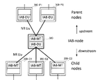
- FIG. 2 is a diagram showing the relationship between the IAB node 300 and the parent nodes (Parent nodes) and child nodes (Child nodes).
- each IAB node 300 has an IAB-DU equivalent to a base station functional unit and an IAB-MT (Mobile Termination) equivalent to a user equipment functional unit.
- IAB-DU equivalent to a base station functional unit
- IAB-MT Mobile Termination
- a neighboring node (ie, upper node) on the NR Uu radio interface of an IAB-MT is called a parent node.
- the parent node is the DU of the parent IAB node or donor node 200 .
- a radio link between an IAB-MT and a parent node is called a backhaul link (BH link).
- FIG. 2 shows an example in which the parent nodes of IAB node 300 are IAB nodes 300-P1 and 300-P2. Note that the direction toward the parent node is called upstream.
- the upper node of the UE 100 can correspond to the parent node.
- Adjacent nodes (ie, lower nodes) on the NR access interface of the IAB-DU are called child nodes.
- IAB-DU like gNB200, manages the cell.
- the IAB-DU terminates the NR Uu radio interface to the UE 100 and subordinate IAB nodes.
- IAB-DU supports the F1 protocol to the CU of donor node 200-1.
- FIG. 2 shows an example in which child nodes of IAB node 300 are IAB nodes 300-C1 to 300-C3, but child nodes of IAB node 300 may include UE100. Note that the direction toward a child node is called downstream.
- all IAB nodes 300 connected to the donor node 200 via one or more hops have a directed acyclic graph (DAG) topology (hereinafter referred to as (sometimes referred to as "topology").
- DAG directed acyclic graph
- adjacent nodes on the IAB-DU interface are child nodes
- adjacent nodes on the IAB-MT interface are parent nodes, as shown in FIG.
- the donor node 200 centralizes, for example, IAB topology resources, topology, route management, and the like.
- Donor node 200 is a gNB that provides network access to UE 100 via a network of backhaul links and access links.
- FIG. 3 is a diagram showing a configuration example of the gNB 200.
- the gNB 200 has a wireless communication unit 210, a network communication unit 220, and a control unit 230.
- the wireless communication unit 210 performs wireless communication with the UE 100 and wireless communication with the IAB node 300.
- the wireless communication section 210 has a receiving section 211 and a transmitting section 212 .
- the receiver 211 performs various types of reception under the control of the controller 230 .
- Reception section 211 includes an antenna, converts (down-converts) a radio signal received by the antenna into a baseband signal (reception signal), and outputs the baseband signal (reception signal) to control section 230 .
- the transmission section 212 performs various transmissions under the control of the control section 230 .
- the transmitter 212 includes an antenna, converts (up-converts) a baseband signal (transmission signal) output from the controller 230 into a radio signal, and transmits the radio signal from the antenna.
- the network communication unit 220 performs wired communication (or wireless communication) with the 5GC 10 and wired communication (or wireless communication) with other adjacent gNBs 200.
- the network communication section 220 has a receiving section 221 and a transmitting section 222 .
- the receiving section 221 performs various types of reception under the control of the control section 230 .
- the receiver 221 receives a signal from the outside and outputs the received signal to the controller 230 .
- the transmission section 222 performs various transmissions under the control of the control section 230 .
- the transmission unit 222 transmits the transmission signal output by the control unit 230 to the outside.
- the control unit 230 performs various controls in the gNB200.
- Control unit 230 includes at least one memory and at least one processor electrically connected to the memory.
- the memory stores programs executed by the processor and information used for processing by the processor.
- the processor may include a baseband processor and a CPU (Central Processing Unit).
- the baseband processor modulates/demodulates and encodes/decodes the baseband signal.
- the CPU executes programs stored in the memory to perform various processes.
- the processor processes each layer, which will be described later.
- the control unit 230 may perform each process in the gNB 200 (or the donor node 200) in each embodiment described below.
- FIG. 4 is a diagram showing a configuration example of the IAB node 300.
- the IAB node 300 has a radio communication section 310 and a control section 320 .
- the IAB node 300 may have multiple wireless communication units 310 .
- the wireless communication unit 310 performs wireless communication (BH link) with the gNB 200 and wireless communication (access link) with the UE 100.
- the wireless communication unit 310 for BH link communication and the wireless communication unit 310 for access link communication may be provided separately.
- the wireless communication unit 310 has a receiving unit 311 and a transmitting unit 312.
- the receiver 311 performs various types of reception under the control of the controller 320 .
- Receiving section 311 includes an antenna, converts (down-converts) a radio signal received by the antenna into a baseband signal (reception signal), and outputs the baseband signal (reception signal) to control section 320 .
- the transmission section 312 performs various transmissions under the control of the control section 320 .
- the transmitter 312 includes an antenna, converts (up-converts) a baseband signal (transmission signal) output from the controller 320 into a radio signal, and transmits the radio signal from the antenna.
- the control unit 320 performs various controls in the IAB node 300.
- Control unit 320 includes at least one memory and at least one processor electrically connected to the memory.
- the memory stores programs executed by the processor and information used for processing by the processor.
- a processor may include a baseband processor and a CPU.
- the baseband processor modulates/demodulates and encodes/decodes the baseband signal.
- the CPU executes programs stored in the memory to perform various processes.
- the processor processes each layer, which will be described later.
- the control unit 320 may perform each process in the IAB node 300 in each embodiment described below.
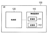
- FIG. 5 is a diagram showing a configuration example of the UE 100. As shown in FIG. As shown in FIG. 5 , UE 100 has radio communication section 110 and control section 120 .
- the wireless communication unit 110 performs wireless communication on the access link, that is, wireless communication with the gNB 200 and wireless communication with the IAB node 300. Also, the radio communication unit 110 may perform radio communication on the sidelink, that is, radio communication with another UE 100 .
- the radio communication unit 110 has a receiving unit 111 and a transmitting unit 112 .
- the receiver 111 performs various types of reception under the control of the controller 120 .
- Reception section 111 includes an antenna, converts (down-converts) a radio signal received by the antenna into a baseband signal (reception signal), and outputs the baseband signal (reception signal) to control section 120 .
- the transmitter 112 performs various transmissions under the control of the controller 120 .
- the transmitter 112 includes an antenna, converts (up-converts) a baseband signal (transmission signal) output from the controller 120 into a radio signal, and transmits the radio signal from the antenna.
- the control unit 120 performs various controls in the UE 100.
- Control unit 120 includes at least one memory and at least one processor electrically connected to the memory.
- the memory stores programs executed by the processor and information used for processing by the processor.
- a processor may include a baseband processor and a CPU.
- the baseband processor modulates/demodulates and encodes/decodes the baseband signal.
- the CPU executes programs stored in the memory to perform various processes.
- the processor processes each layer, which will be described later.
- the control unit 130 may perform each process in the UE 100 in each embodiment described below.
- FIG. 6 is a diagram showing an example of protocol stacks for IAB-MT RRC connection and NAS connection.
- the IAB-MT of the IAB node 300-2 includes a physical (PHY) layer, a MAC (Medium Access Control) layer, an RLC (Radio Link Control) layer, and a PDCP (Packet Data Convergence Protocol) layer, RRC (Radio Resource Control) layer, and NAS (Non-Access Stratum) layer.
- PHY physical
- MAC Medium Access Control
- RLC Radio Link Control
- PDCP Packet Data Convergence Protocol
- RRC Radio Resource Control
- NAS Non-Access Stratum
- the PHY layer performs encoding/decoding, modulation/demodulation, antenna mapping/demapping, and resource mapping/demapping. Data and control information are transmitted via physical channels between the IAB-MT PHY layer of the IAB node 300-2 and the IAB-DU PHY layer of the IAB node 300-1.
- the MAC layer performs data priority control, hybrid ARQ (HARQ) retransmission processing, random access procedures, and so on. Data and control information are transmitted via transport channels between the MAC layer of the IAB-MT of the IAB node 300-2 and the MAC layer of the IAB-DU of the IAB node 300-1.
- the MAC layer of IAB-DU contains the scheduler. The scheduler determines uplink and downlink transport formats (transport block size, modulation and coding scheme (MCS)) and allocation resource blocks.
- MCS modulation and coding scheme
- the RLC layer uses the functions of the MAC layer and PHY layer to transmit data to the RLC layer on the receiving side. Data and control information are transmitted over logical channels between the IAB-MT RLC layer of IAB node 300-2 and the IAB-DU RLC layer of IAB node 300-1.
- the PDCP layer performs header compression/decompression and encryption/decryption. Data and control information are transmitted between the IAB-MT PDCP layer of IAB node 300-2 and the PDCP layer of donor node 200 via radio bearers.
- the RRC layer controls logical channels, transport channels and physical channels according to radio bearer establishment, re-establishment and release. Between the IAB-MT RRC layer of the IAB node 300-2 and the RRC layer of the donor node 200, RRC signaling for various settings is transmitted. If there is an RRC connection with the donor node 200, the IAB-MT is in RRC connected state. When there is no RRC connection with the donor node 200, the IAB-MT is in RRC idle state.
- the NAS layer located above the RRC layer performs session management and mobility management.
- NAS signaling is transmitted between the NAS layer of the IAB-MT of the IAB node 300-2 and the AMF 11.
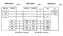
- FIG. 7 is a diagram representing the protocol stack for the F1-U protocol.
- FIG. 8 is a diagram representing a protocol stack for the F1-C protocol.
- the donor node 200 is split into CUs and DUs.
- each of the IAB-MT of the IAB node 300-2, the IAB-DU of the IAB node 300-1, the IAB-MT of the IAB node 300-1, and the DU of the donor node 200 is It has a BAP (Backhaul Adaptation Protocol) layer as an upper layer.
- the BAP layer is a layer that performs routing processing and bearer mapping/demapping processing.
- the IP layer is transported over the BAP layer to allow routing over multiple hops.
- BAP layer PDUs Protocol Data Units
- backhaul RLC channels BH NR RLC channels
- Traffic prioritization and QoS control are possible by configuring multiple backhaul RLC channels on each BH link.
- the association between BAP PDUs and backhaul RLC channels is performed by the BAP layer of each IAB node 300 and the BAP layer of the donor node 200 .
- the CU of the donor node 200 is the gNB-CU function of the donor node 200 that terminates the F1 interface to the IAB node 300 and the DU of the donor node 200.
- DU of donor node 200 is also the gNB-DU function of donor node 200 that hosts the IAB BAP sublayer and provides wireless backhaul to IAB node 300 .
- the F1-C protocol stack has an F1AP layer and an SCTP layer instead of the GTP-U layer and UDP layer shown in FIG.
- the processing or operations performed by the IAB's IAB-DU and IAB-MT may be simply described as "IAB" processing or operations.
- the IAB-DU of the IAB node 300-1 sends a BAP layer message to the IAB-MT of the IAB node 300-2, and the IAB node 300-1 sends the message to the IAB node 300-2.
- DU or CU processing or operations of donor node 200 may also be described simply as "donor node” processing or operations.
- the upstream direction and the uplink (UL) direction may be used without distinction.
- the downstream direction and the downlink (DL) direction may be used interchangeably.
- the BSR transmitted by the UE 100 (hereinafter referred to as “regular BSR” as appropriate.) is the untransmitted uplink data amount of each layer of MAC, RLC, and PDCP (that is, the amount of uplink buffer) is a logical channel It shows for each group (LCG).
- Each LCG is a group consisting of at least one logical channel and set according to priority.
- gNB 200 grasps the untransmitted uplink data amount of UE 100 for each LCG, and performs scheduling so as to allocate uplink radio resources to UE 100 in accordance with the untransmitted uplink data amount. conduct.
- FIG. 9(A) is a diagram showing an example of regular BSR transmission between IAB nodes.
- FIG. 9A shows an example in which the IAB node 300-2 transmits a regular BSR to the parent node 300-1 after receiving data from the child node 300-3.
- the IAB node 300-2 uses the regular BSR as the buffer size for the amount of data waiting to be sent (or the amount of buffered data) existing in the IAB node 300-2 (MAC and RLC of the IAB-MT). Report to parent node 300-1. Then, an uplink radio resource corresponding to this data amount is allocated from the parent node 300-1. IAB node 300-2 then transmits the data to parent node 300-1 using radio resources.
- FIGS. 9(B) and 9(C) are diagrams showing transmission examples of pre-emptive BSR.
- the IAB node 300-2 transmits a preemptive BSR after transmitting the UL grant to the child node 300-3 and before receiving UL data from the child node 300-3.
- the IAB node 300-2 after receiving the regular BSR from the child node 300-3, transmits a preemptive BSR before transmitting the UL grant to the child node 300-3. do.
- the preemptive BSR is transmitted to the parent node 300-1 earlier than the regular BSR. Therefore, it is possible to reduce the UL scheduling delay of the parent node 300-1 to the IAB node 300-2 as compared with the regular BSR.
- FIG. 10 is a diagram showing a configuration example of the Pre-emptive BSR MAC CE.
- a preemptive BSR is transmitted using MAC CE, similar to a regular BSR.
- the Pre-emptive BSR MAC CE includes LCG i and buffer size fields.
- LCG i is an area indicating that the buffer size of logical channel group i exists. That is, when LCG i is set to '1', it indicates that the buffer size of logical channel group i is reported. On the other hand, if LCG i is set to '0', it indicates that the buffer size for logical channel group i is not reported.
- the buffer size identifies the total amount of data expected to arrive at the IAB-MT of the IAB node 300 where the preemptive BSR was triggered, and does not include the total amount of data currently available at the IAB-MT.
- the preemptive BSR has been explained above, but it can be summarized as follows.
- A1 A UL grant is provided to a child node or UE.
- A2) Receive a BSR from a child node or UE.
- preemptive BSR triggers are defined in this way, the reported LCG i , calculation of expected data amount, related LCH (Logical Channel), etc. are implementation dependent.
- the IAB node 300-2 (hereinafter referred to as “child node 300-2”) ) is not known.
- Parent node 300-1 allocates radio resources for UL data of child node 300-2 immediately before child node 300-2 transmits UL data, and if UL grant can be transmitted to child node 300-2, appropriate UL grant can be sent at appropriate timing.
- the parent node 300-1 since the parent node 300-1 does not know the transmission timing of the UL data, it may not be able to transmit the UL grant at the appropriate timing.
- the buffer size included in the preemptive BSR as described above, "identify the total amount of data expected to arrive at the IAB-MT of the IAB node 300 where the preemptive BSR was triggered, and It does not include the total amount of data currently available.”
- the buffer size is implementation-dependent, is "data expected to arrive at the IAB-MT of the IAB node 300" data buffered in the IAB-DU of the child node 300-2? It is unknown whether it is the data buffered in the IAB-MT of the IAB node 300-3, which is the child node of the child node 300-2, or whether it includes both.
- the preemptive BSR is triggered at different timings in (A1) and (A2).
- the buffer size may also differ between (A1) and (A2).
- Parent node 300-1 that receives the buffer size report cannot accurately predict the buffer size. Therefore, the parent node 300-1 that received the report cannot generate an appropriate UL grant and transmit the appropriate UL grant to the child node 300-2.
- the donor node sets to the IAB node transmitting the preemptive BSR which event, (A1) or (A2), triggers the preemptive BSR.
- a parent node that receives a preemptive BSR cannot determine which event triggers (or sends) a preemptive BSR. )do not know. Therefore, the parent node may not know the timing of receiving UL data, and may not be able to transmit an appropriate UL grant at appropriate timing.
- the donor node 200 transmits the trigger type of the preemptive BSR set in the child node 300-2 to the parent node 300-1.
- a donor base station for example, donor node 200 having first and second relay nodes under its control has a second relay node (for example, child node 300-2) that is a parent node of the first relay node (for example, child node 300-2). to the relay node (for example, parent node 300-1) of the preemptive BSR.
- the donor base station transmits the trigger type set in the first relay node to the second relay node.
- the first relay node triggers a preemptive BSR to the second relay node according to the trigger type.
- FIG. 11 is a diagram showing a setting example according to the first embodiment.
- "trigger type” is information representing one of the events (or timing) of (A1) and (A2). Also, hereinafter, the terms “trigger” and “transmission” may be used interchangeably.
- FIG. 11 shows an example in which at least one IAB node exists between the donor node 200 and the IAB node 300-P.
- An IAB node 300-P may exist directly below.
- the IAB node 300-P is the parent node of the IAB node 300-C.
- the IAB node 300-C is a child node of the IAB node 300-P. Below, they may be referred to as parent node 300-P and child node 300-C.
- the child node 300-C may be the UE100. In this case, when the donor node 200 and the UE 100 are RRC-connected, the donor node 200 can directly configure the UE 100 using an RRC message.
- the donor node 200 first sets the trigger type of preemptive BSR for the child node 300-C. After that, the donor node 200 transmits the trigger type of the preemptive BSR set in the child node 300-C to the parent node 300-P. In other words, the parent node 300-P obtains the trigger type information of the preemptive BSR it receives. Child node 300-C then transmits a preemptive BSR to parent node 300-P according to the set trigger type.
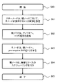
- FIG. 12 is a diagram showing an operation example according to the first embodiment. The operation example shown in FIG. 12 will be described using the relationships shown in FIG. 11 as appropriate.
- step S10 the donor node 200 starts processing.
- the donor node 200 sets the trigger type of preemptive BSR to the child node 300-C.
- the CU of donor node 200 may be configured by sending an RRC message to the IAB-MT of child node 300-C.
- the CU of donor node 200 may be configured by sending an F1AP message to the IAB-DU of child node 300-C.
- the parent node 300-P may transmit to the donor node 200 the trigger type (or preference information) used by the child node 300-C. In this case, the donor node 200 sets the trigger type for the child node 300-C in response to this notification.
- the donor node 200 transmits the trigger type set in the child node 300-C to the parent node 300-P.
- Transmission of the trigger type may be performed by an RRC message or an F1AP message as in step S11.
- the parent node 300-P may inquire of the donor node 200 about the current set value of the trigger type. That is, the parent node 300-P may inquire about the trigger type set in the child node 300-C. In this case, donor node 200 sends the trigger type to parent node 300-P in response to the inquiry.
- the donor node 200 may transmit the mapping information between the logical channel group (LCG) and the logical channel (LCH) together with the trigger type to the parent node 300-P.
- LCG 2 LCH 4 to LCH 6 and so on.
- a logical channel group includes at least one or more logical channels.
- the buffer size reported as preemptive BSR is calculated for each logical channel group in which data resides.
- the parent node 300-P grasps the buffer size for each logical channel group and the logical channels included in the logical channel group, which are included in the preemptive BSR, so that QoS (Quality of Service) information is provided for each logical channel. If given, these can be used for scheduling.
- QoS Quality of Service
- the trigger type and/or the mapping information between the logical channel group and the logical channel may be associated with the identifier of the child node 300-C.
- identifiers include UE ID, C-RNTI, F1AP UE ID, and the like.
- step S13 the IAB-MT of the child node 300-C triggers the preemptive BSR to the IAB-DU of the parent node 300-P according to the set trigger type.
- step S14 the IAB-DU of the parent node 300-P schedules radio resources based on the trigger type received from the donor node 200 and the preemptive BSR received from the child node 300-C.
- the IAB-DU of the parent node 300-P transmits the UL grant including the scheduling result to the IAB-MT of the child node 300-C.
- the parent node 300-P ends a series of processes.
- the donor node 200 sets the trigger type of the preemptive BSR set in the child node 300-C to the parent node 300-P (step S12). Therefore, the parent node 300-P can grasp the trigger type set in the child node 300-C, and can grasp whether the preemptive BSR is triggered by either event (A1) or (A2). . Therefore, the parent node 300-P can anticipate the timing and transmit the UL grant at an appropriate timing.
- the parent node 300-P is at least (A1) or (A2) by grasping which event triggered the preemptive BSR, predicting an appropriate buffer size and allocating radio resources is enabled, and an appropriate UL grant can be sent to the child node 300-C.
- the second embodiment is an example in which the parent node 300-P transmits to the child node 300-C the trigger type of the preemptive BSR to be used by the child node 300-C.
- the second relay node eg, parent node 300-P
- the first relay node transfers to the first relay node.
- the first relay node triggers a preemptive BSR to the second relay node according to the trigger type.
- the parent node 300-P can grasp the trigger type triggered by the child node 300-C.
- UL grant can be sent to the child node 300-C.
- FIG. 13A is a diagram showing a transmission example according to the second embodiment.
- Parent node 300-P transmits the trigger type to child node 300-C.
- Child node 300-C triggers a preemptive BSR to parent node 300-P according to the trigger type.
- FIG. 14 is a diagram showing an operation example in the second embodiment.
- step S20 the parent node 300-P starts processing.
- the parent node 300-P transmits the trigger type of preemptive BSR to the child node 300-C.
- This transmission may be an indication of the trigger type to child node 300-C of parent node 300-P.
- the IAB-DU of the parent node 300-P transmits the MAC CE (Control Element) or BAP Control PDU containing the trigger type to the IAB-MT of the child node 300-C, so that the transmission of the trigger type is done.
- SIB1 System Information Block 1 may be used for transmission of the trigger type.
- the donor node 200 may set the parent node 300-P to allow the child node 300-C to use the preemptive BSR.
- 3GPP as an information element included in an RRC message (RRC setup message), there is "usePreBSR" that can set permission to use preemptive BSR.
- FIG. 13B is a diagram showing a configuration example of "usePreBSR" according to the second embodiment.
- donor node 200 sets permission to use preemptive BSR by transmitting an RRC message including “usePreBSR” to child node 300-C.
- the donor node 200 notifies the parent node 300-P that use permission has been set for the child node 300-C. That is, the parent node 300-P may perform the process of step S21 upon being informed by the donor node 200 that the child node 300-C is permitted to use the preemptive BSR.
- the child node 300-C upon receiving the trigger type from the parent node 300-P, applies the received trigger type. good too.
- the child node 300-C may ignore the trigger type received from the parent node 300-P when use permission is not set by the donor node 200 and the trigger type is received from the parent node 300-P.
- the child node 300-C that has received the trigger type may transmit a response indicating whether or not the received trigger type is accepted to the parent node 300-P. For example, if child node 300-C receives an unsupported trigger type, it sends a response to parent node 300-P indicating refusal (or non-acceptance) of acceptance.
- the response may be performed by inserting 1-bit information (whether to accept or not) into the header of the (Pre-emptive) BSR MAC CE, or may be performed separately by a dedicated MAC CE.
- the child node 300-C triggers the preemptive BSR to the parent node 300-P according to the trigger type received from the parent node 300-P.
- step S23 the parent node 300-P performs scheduling based on the trigger type transmitted to the child node 300-C and the preemptive BSR received from the child node 300-C.
- the parent node 300-P then transmits the UL grant to the child node 300-C.
- the parent node 300-P ends the series of processes.
- a modification is an example in which the donor node 200 sets the parent node 300-P so that the trigger type of the child node 300-C may be determined.
- a donor base station for example, donor node 200
- a second relay node for example, parent node 300-P
- the configured second relay node transmits the trigger type to the first relay node.
- FIG. 15A is a diagram showing a setting example according to a modification of the second embodiment.
- FIG. 15B is a diagram showing an operation example according to the modification of the second embodiment. An operation example according to the modification will be described with reference to FIG. 15(B) while appropriately referring to FIG. 15(A).
- the donor node 200 starts processing in step S30.
- the donor node 200 sets permission for the parent node 300-P to determine the trigger type of the child node 300-C.
- Such settings are performed using, for example, RRC messages or F1AP messages.
- step S21 that is, the processing in which the parent node 300-P transmits the trigger type to the child node 300-C, etc. are performed.
- the child node 300-C may determine that permission has been received from the notification from the parent node 300-P, even if the donor node 200 does not set permission for preemptive BSR.
- Parent node 300 -P may further notify child node 300 -C that it has obtained permission from donor node 200 .
- the parent node 300-P can receive the permission setting from the donor node 200 and set the trigger type for the child node 300-C.
- the third embodiment is an example in which the child node 300-C transmits the trigger type of the preemptive BSR used by the child node 300-C to the parent node 300-P.
- a first relay node for example, child node 300-C
- a second relay node for example, parent node 300-P
- the first relay node triggers a preemptive BSR to the second relay node according to the trigger type.
- the parent node 300-P since the parent node 300-P receives the trigger type used by the child node 300-C from the child node 300-C, it can grasp the trigger type used by the child node 300-C. Therefore, the parent node 300-P can transmit an appropriate UL grant at appropriate timing, as in the first embodiment.
- FIG. 16(A) is a diagram showing a transmission example according to the third embodiment.
- Child node 300-C transmits the trigger type to parent node 300-P.
- the trigger type of the child node 300-C may be set by the donor node 200 or determined depending on the implementation of the child node 300-C.
- the child node 300-C then triggers the preemptive BSR to the parent node 300-P according to the transmitted trigger type.
- FIG. 16(B) is a diagram showing an operation example according to the third embodiment.
- step S40 the child node 300-C starts processing.
- the child node 300-C transmits the trigger type used by the child node 300-C to the parent node 300-P.
- the child node 300-C may transmit the trigger type when the trigger type is set by the donor node 200, or may transmit the trigger type when the trigger type is set by the child node 300-C. good too.
- child node 300-C may transmit the trigger type each time it transmits a preemptive BSR. Transmission of the trigger type may be performed using MAC CE or BAP Control PDU.
- the trigger type When the trigger type is expressed as 1-bit information in the header of the Pre-emptive BSR MAC CE, the trigger type may be (dynamically) changed each time the preemptive BSR is transmitted. For example, when the first preemptive BSR is triggered, the child node 300-C inserts (A1) as 1-bit information into the header of the pre-emptive BSR MAC CE, and triggers the preemptive BSR at the timing of (A1). trigger. Then, when transmitting the next preemptive BSR, the child node 300-C inserts (A2) as 1-bit information into the header portion, and triggers the preemptive BSR at the timing of (A2).
- the trigger type When the trigger type is transmitted by a dedicated MAC CE, the trigger type may be fixed after this transmission until the next trigger type is transmitted by the dedicated MAC CE.
- the buffer size (BS) is also reported by the corresponding MAC CE.
- BS buffer size
- step S42 the child node 300-C triggers the preemptive BSR according to the trigger type sent to the parent node 300-P.
- step S43 the parent node 300-P performs scheduling based on the trigger type received from the child node 300-C and the preemptive BSR received from the child node 300-C.
- the parent node 300-P then transmits the UL grant to the child node 300-C.
- the parent node 300-P terminates the series of processes.
- a modification of the third embodiment is an example in which the donor node 200 sets the child node 300-C to allow dynamic trigger determination.
- a donor base station eg, donor node 200
- first and second relay nodes under its control sends a trigger type to the first relay node (eg, child node 300-C). Make settings that allow you to decide.
- the configured first relay node transmits the trigger type to the second relay node (eg, parent node 300-P).
- the child node 300-C itself dynamically changes the trigger type.
- FIG. 17 is a diagram showing a setting example according to a modification of the third embodiment.
- donor node 200 sets dynamic trigger decision permissions for child node 300-C.
- the child node 300-C determines the trigger type by itself and triggers the preemptive BSR.
- FIG. 18 is a diagram showing an operation example according to the modification of the third embodiment.
- the donor node 200 starts processing.
- the donor node 200 sets the child node 300-C to allow dynamic trigger determination.
- Permission for dynamic trigger determination may be permission for the child node 300-C itself to determine the trigger type.
- Such configuration may be done using RRC messages or F1AP messages.
- “event (A1)”, “event (A2)”, and “dynamic trigger determination” are listed in the message, and one of them is selected. may be expressed.
- step S52 the child node 300-C determines the trigger type by itself, and triggers the preemptive BSR to the parent node 300-P according to the determined trigger type.
- the child node 300-C sends the trigger type to the parent node 300-P before, during or after sending the preemptive BSR. Transmission of the trigger type to the parent node 300-P itself is the same as in the third embodiment.
- the parent node 300-P receives the trigger type from the child node 300-C, so as in the first embodiment, etc., it transmits an appropriate UL grant to the child node 300-C at an appropriate timing. can.
- the donor node 200 sets permission for dynamic trigger determination to the child node 300-C. may be permitted.
- parent node 300-P may make the authorization by sending a MAC CE or BAP Control PDU containing authorization for the decision to child node 300-C.
- the fourth embodiment is an example in which the donor node 200 sets the trigger type to the parent node 300-P, and the parent node 300-P transmits the trigger type to the child node 300-C.
- a donor base station for example, donor node 200 having first and second relay nodes under its control is the parent node of the first relay node (for example, child node 300-C).
- the second relay node for example, the parent node 300-P
- the preemptive BSR trigger type the second relay node
- the second relay node sends the trigger type to the first relay node.
- the first relay node triggers the preemptive BSR according to the trigger type received from the second relay node.
- the parent node 300-P receives the setting of the trigger type used by the child node 300-C from the donor node 200, so it can grasp the trigger type used by the child node 300-C. Therefore, also in the fourth embodiment, the parent node 300-P can transmit an appropriate UL grant to the child node 300-C at appropriate timing, as in the first embodiment.
- FIG. 19 is a diagram showing a setting example according to the fourth embodiment.
- the donor node 200 sets the trigger type of the preemptive BSR used by the child node 300-C to the parent node 300-P. Then, the parent node 300-P transmits the trigger type set by the donor node 200 to the child node 300-C. Child node 300-C triggers the preemptive BSR according to the trigger type received from parent node 300-P.
- FIG. 20 is a diagram showing an operation example according to the fourth embodiment.
- step S60 the donor node 200 starts processing.
- the donor node 200 sets the trigger type used by the child node 300-C to the parent node 300-P.
- the setting of the trigger type is performed by an RRC message or F1AP message, or BAP Control PDU or MAC CE.
- the parent node 300-P may send the donor node 200 the trigger type (or preference information) used by the child node 300-C.
- the donor node 200 sets the trigger type to the parent node 300-P in response to receiving the trigger type.
- the setting of the trigger type to the parent node 300-P by the donor node 200 may use the modified example of the second embodiment instead of the setting.
- the donor node 200 may set permission for the parent node 300-P to determine the trigger type of the child node 300-C.
- the parent node 300-P receives this permission setting and transmits the trigger type to the child node 300-C.
- the setting of the trigger type to the parent node 300-P by the donor node 200 may use the modified example of the third embodiment instead of the setting. That is, the donor node 200 may set permission for the parent node 300-P to allow the child node 300-C to determine the trigger type by itself.
- the parent node 300-P receives this permission setting and notifies the child node 300-C of permission to determine the trigger type by itself, and the child node 300-C Upon receiving this notification, the trigger type is determined by itself.
- the parent node 300-P transmits the trigger type of preemptive BSR to the child node 300-C.
- MAC CE or BAP Control PDU may be used to transmit the trigger type.
- the child node 300-C that has received the trigger type may transmit a response of acceptability to the parent node 300-P as in step S21 (FIG. 14) of the second embodiment.
- step S63 the child node 300-C transmits a preemptive BSR to the parent node 300-P according to the trigger type received from the parent node 300-P.
- step S64 the parent node 300-P performs scheduling based on the trigger type set by the donor node 200 and the preemptive BSR received from the child node 300-C.
- Parent node 300-P transmits the UL grant to child node 300-C.
- the fifth embodiment is an example of transmitting the trigger type to all IAB nodes 300 included in the entire topology constructed by the donor node 200 .
- a donor base station having a plurality of relay nodes under its control eg, donor node 200
- all relay nodes trigger preemptive BSR according to the trigger type.
- FIG. 21 is a diagram showing a setting example according to the fifth embodiment.
- FIG. 21 shows an example in which one IAB node 300 is connected to the donor node 200 and one IAB node 300-2 is connected to the IAB node 300-1.
- a plurality of IAB nodes 300 may be connected directly under the donor node 200, or a plurality of IAB nodes 300 may be connected as child nodes of the IAB node 300-1.
- the donor node 200 and each IAB node 300 may have a plurality of IAB nodes connected directly below them.
- the node arranged on the farthest side from the network may be the IAB node or the UE 100.
- FIG. 22 is a diagram showing an operation example according to the fifth embodiment. The operation example of FIG. 22 will be described with reference to FIG. 21 as appropriate.
- step S70 the donor node 200 starts processing.
- the donor node 200 transmits the trigger type of preemptive BSR to the IAB node 300-1 directly under it.
- Transmission of the trigger type may be performed by an RRC message or may be performed by an F1AP message.
- transmission of the trigger type may use MAC CE or BAP PDU Control.
- the IAB node 300-1 transmits the trigger type received from the donor node 200 to the IAB node 300-2, which is its own child node. Transmission of the trigger type may use MAC CE or BAP Control PDU.
- step S73 the IAB node 300-2 transmits the trigger type received from the IAB node 300-1 to the IAB node 300-3, which is its own child node.
- each IAB node 300 or UE 100 triggers a preemptive BSR to the donor node 200 or parent node 300 according to the received trigger type.
- step S75 the donor node 200 or parent node 300 performs scheduling based on the transmitted trigger type and the received preemptive BSR, and transmits the UL grant to the child node 300 or UE100.
- step S76 the donor node 200 or parent node 300 terminates a series of processes.
- all IAB nodes 300 or UEs 100 within the topology can transmit preemptive BSRs according to the same trigger type. Therefore, also in the fifth embodiment, the parent node 300 or the donor node 200 can transmit an appropriate UL grant to the child node 300 or the UE 100 at appropriate timing, as in the first embodiment.
- a program that causes a computer to execute each process performed by the UE 100, the gNB 200, or the IAB node 300 may be provided.
- the program may be recorded on a computer readable medium.
- a computer readable medium allows the installation of the program on the computer.
- the computer-readable medium on which the program is recorded may be a non-transitory recording medium.
- the non-transitory recording medium is not particularly limited, but may be, for example, a recording medium such as CD-ROM or DVD-ROM.
- the UE 100, the gNB 200, or a circuit that executes each process performed by the IAB node 300 may be integrated, and at least a portion of the UE 100, the gNB 200, or the IAB node 300 may be configured as a semiconductor integrated circuit (chipset, SoC). .
- chipsset semiconductor integrated circuit
- IL-2 Multi-hop latency IL-2 IL-2 is defined as follows. IL-2: Due to current (Rel-16) limitations on the number of LCGs, IAB nodes may need to report joint buffer status for LCHs with significantly different QoS requirements.
- L4 A new operation or function is specified for an IAB node.
- L4-3 The number of LCGs in IAB-MT increases.
- the number of UE LCGs was reused for IAB-MT. That is, up to 8 LCGs.
- IAB nodes need to report legacy and preemptive BSRs with LCG restrictions. Therefore, expanding the LCG space is expected to reduce the number of LCHs aggregated within each LCG, finer scheduling granularity, and improve fairness across the topology, so RAN2 increases the number of LCGs. There is a need. This is applicable to both legacy BSR and preemptive BSR.
- Proposal 1 RAN2 should agree to increase the number of LCGs for BSR and preemptive BSR. That is, use L4-3 to resolve IL-2.
- IL-3 IL-3 is defined as follows. IL-3: Preemptive BSR buffer size calculation is left to the implementation in Rel-16 and may vary from vendor to vendor.
- L4 A new operation or function is specified for an IAB node.
- L4-1 Preemptive BSR buffer size calculation is specified.
- the IAB node has a BAP layer instead of PDCP, and the BAP specification does not calculate the amount of data. Therefore, the current specification lacks data that can be used for transmission. To better schedule fairness across the topology, the buffer size reported in the legacy BSR needs to be more accurate.
- the calculation of the preemptive BSR buffer size is highly dependent on the IAB-DU implementation.
- the specification states that "the buffer size field identifies the total amount of data expected to arrive at the IAB-MT of the node where preemptive BSR is triggered, and does not include the amount of data currently available.” outlines the guidelines.
- some IAB nodes may report larger buffer sizes in preemptive BSRs than they actually arrive.
- Using the same principles between child and parent nodes can be difficult. For example, in multi-vendor deployments, radio resource allocation and scheduling delays at parent nodes become inefficient and resource requests between IABs-MTs become unfair.
- the buffer size calculation for preemptive BSR needs to be defined more precisely.
- the problem is that the IAB-DU does not specify the calculation of the buffer size. That is, the buffered data at the receiving end of the IAB-DU (MAC and RLC).
- Proposal 3 RAN2 should agree to define buffer size calculation for preemptive BSR (and possibly legacy BSR), ie take L4-1 to solve IL-3.
- the MAC specification describes the following two conditions. That is, the trigger condition depends on the implementation of IAB-MT in Rel-16. In other words, inappropriate UL grants occur because it is not possible to accurately predict when the parent node will be ready to send data.
- any of the following events may trigger a preemptive BSR in the specific case of IAB-MT.
- a UL grant is provided to the child IAB node or UE.
- Proposal 4 RAN2 should agree that IAB nodes set the triggers used for preemptive BSR. Whether done by the IAB donor or its parent IAB node requires further consideration.
- IL-5 and IL-6 IL-5 is defined as follows.
- IL-5 The CU cannot place a bearer with a low PDB on a path with low congestion risk (high resource efficiency) or no RLF.
- L3-1 Share the IAB node's buffer/link state with the CU.
- L3-2 BH Share the hop-by-hop delay measurement for each RLC channel with the CU.
- L4 New operations and functions are specified for IAB nodes.
- L4-2 Allow local rerouting for purposes other than RLF (eg, based on outgoing link delay).
- F4 Introduce additional signaling from the IAB node to the CU.
- F4-1 BH RLC Concerning load information for each channel.
- F4-2 Concerning the delay for each hop of individual links and the packet loss for each hop.
- IL-6 is defined as follows. IL-6: CU cannot set routing based on actual (real-time) latency per BH RLC channel.
- L3-2 BH Share per-hop delay measurements for each RLC channel with the CU.
- F4 Introduce additional signaling from the IAB node to the CU.
- F4-2 Concerning the delay for each hop of individual links and the packet loss for each hop.
- L4 New operations and functions are specified for IAB nodes.
- L4-2 Allow local rerouting for purposes other than RLF (eg, based on outgoing link delay).
- the IL-5 and IL-6 solutions may have in common an additional signal from the IAB node to the IAB donor. It can thus be seen as a kind of SON procedure pointed out in MDT to enable centralized optimization.
- both IL-5 and IL-6 are solutions that can be used in common, and can be considered the same in terms of latency measurement.
- the existing L2 measurement specifies "UL PDCP Packet Average Delay per DRB per UE", but it is clear that PDCP Packet Average Delay cannot be applied to IAB nodes. Therefore, it is expected that a new L2 measurement considering at least BAP is necessary.
- Proposal 3 RAN2 should agree that IAB nodes report hop-by-hop delay measurements to IAB donors, ie, take L3-2 to resolve IL-5 and IL-6.
- RAN2 has already agreed that "the indication of Type-2 RLF can be used as a trigger for local rerouting" and "local rerouting can be triggered by the indication of hop-by-hop flow control". Therefore, no further discussion is necessary on this topic. That is, the details of local rerouting can be discussed in other topics for topology adaptation enhancements.
- IC-1 and IC-7 are defined with the following remarks.
- R2 judges that each company has a sufficiently high level of interest in the following two issues.
- IC-1 Prolonged downstream congestion on a single link cannot be mitigated using existing Rel-16 DL HbH flow control mechanisms without resorting to dropping packets.
- IC-7 The CU cannot update the congested route (because it does not know the local congestion situation).
- RAN3 has discussed congestion indications and agreed as follows.
- CP-based congestion indications can include announcements.
- CP-based congestion indication reuses the F1AP GNB-DU status indication procedure.
- CP-based congestion indication is related to DL congestion.
- the IAB donor receives a congestion indication from an IAB node, the IAB donor will avoid the congested path as implied in the RAN2 agreement above It is assumed that That is, we can think of two ways: the IAB donor updates the routing configuration or directs local rerouting. In the latter case, RAN2 may be involved in how the congestion indication is used. In any case, RAN2 should wait for RAN3's progress at this point.
- RAN2 may be involved in how IAB donors take action with congestion indications after RAN3 has learned the details.
Landscapes
- Engineering & Computer Science (AREA)
- Computer Networks & Wireless Communication (AREA)
- Signal Processing (AREA)
- Mobile Radio Communication Systems (AREA)
Priority Applications (2)
| Application Number | Priority Date | Filing Date | Title |
|---|---|---|---|
| JP2023509212A JP7720903B2 (ja) | 2021-03-26 | 2022-03-22 | 通信制御方法 |
| US18/474,494 US20240015580A1 (en) | 2021-03-26 | 2023-09-26 | Communication control method |
Applications Claiming Priority (2)
| Application Number | Priority Date | Filing Date | Title |
|---|---|---|---|
| US202163166507P | 2021-03-26 | 2021-03-26 | |
| US63/166,507 | 2021-03-26 |
Related Child Applications (1)
| Application Number | Title | Priority Date | Filing Date |
|---|---|---|---|
| US18/474,494 Continuation US20240015580A1 (en) | 2021-03-26 | 2023-09-26 | Communication control method |
Publications (1)
| Publication Number | Publication Date |
|---|---|
| WO2022202835A1 true WO2022202835A1 (ja) | 2022-09-29 |
Family
ID=83395865
Family Applications (1)
| Application Number | Title | Priority Date | Filing Date |
|---|---|---|---|
| PCT/JP2022/013269 Ceased WO2022202835A1 (ja) | 2021-03-26 | 2022-03-22 | 通信制御方法 |
Country Status (3)
| Country | Link |
|---|---|
| US (1) | US20240015580A1 (https=) |
| JP (1) | JP7720903B2 (https=) |
| WO (1) | WO2022202835A1 (https=) |
Families Citing this family (1)
| Publication number | Priority date | Publication date | Assignee | Title |
|---|---|---|---|---|
| US12309704B2 (en) * | 2022-05-26 | 2025-05-20 | Qualcomm Incorporated | Pre-emptive buffer status report extension for network power saving |
-
2022
- 2022-03-22 JP JP2023509212A patent/JP7720903B2/ja active Active
- 2022-03-22 WO PCT/JP2022/013269 patent/WO2022202835A1/ja not_active Ceased
-
2023
- 2023-09-26 US US18/474,494 patent/US20240015580A1/en active Pending
Non-Patent Citations (4)
| Title |
|---|
| ITRI: "Trigger Conditions for low-latency IAB Uplink Scheduling", 3GPP DRAFT; R2-1915068, 3RD GENERATION PARTNERSHIP PROJECT (3GPP), MOBILE COMPETENCE CENTRE ; 650, ROUTE DES LUCIOLES ; F-06921 SOPHIA-ANTIPOLIS CEDEX ; FRANCE, vol. RAN WG2, no. Reno, USA; 20191118 - 20191122, 8 November 2019 (2019-11-08), Mobile Competence Centre ; 650, route des Lucioles ; F-06921 Sophia-Antipolis Cedex ; France , XP051816993 * |
| KYOCERA: "Possible solutions for topology-wide fairness, multi-hop latency and congestion mitigation in eIAB", 3GPP DRAFT; R2-2105509, 3RD GENERATION PARTNERSHIP PROJECT (3GPP), MOBILE COMPETENCE CENTRE ; 650, ROUTE DES LUCIOLES ; F-06921 SOPHIA-ANTIPOLIS CEDEX ; FRANCE, vol. RAN WG2, no. Online; 20210519 - 20210527, 11 May 2021 (2021-05-11), Mobile Competence Centre ; 650, route des Lucioles ; F-06921 Sophia-Antipolis Cedex ; France , XP052007087 * |
| KYOCERA: "Remaining issue of pre-emptive BSR in IAB", 3GPP DRAFT; R2-2000514, 3RD GENERATION PARTNERSHIP PROJECT (3GPP), MOBILE COMPETENCE CENTRE ; 650, ROUTE DES LUCIOLES ; F-06921 SOPHIA-ANTIPOLIS CEDEX ; FRANCE, vol. RAN WG2, no. Online; 20200224 - 20200306, 14 February 2020 (2020-02-14), Mobile Competence Centre ; 650, route des Lucioles ; F-06921 Sophia-Antipolis Cedex ; France , XP051849095 * |
| QUALCOMM INCORPORATED: "Interruption time reduction for Intra-donor IAB-node Migration", 3GPP DRAFT; R3-206257, 3RD GENERATION PARTNERSHIP PROJECT (3GPP), MOBILE COMPETENCE CENTRE ; 650, ROUTE DES LUCIOLES ; F-06921 SOPHIA-ANTIPOLIS CEDEX ; FRANCE, vol. RAN WG3, no. E-meeting; 20201102 - 20201112, 22 October 2020 (2020-10-22), Mobile Competence Centre ; 650, route des Lucioles ; F-06921 Sophia-Antipolis Cedex ; France , XP051941710 * |
Also Published As
| Publication number | Publication date |
|---|---|
| JP7720903B2 (ja) | 2025-08-08 |
| JPWO2022202835A1 (https=) | 2022-09-29 |
| US20240015580A1 (en) | 2024-01-11 |
Similar Documents
| Publication | Publication Date | Title |
|---|---|---|
| US11950124B2 (en) | Methods, apparatus and systems for integrated access and backhaul bearer management | |
| US20210329530A1 (en) | Method and apparatus for supporting communication via a relay wireless device | |
| KR20230035038A (ko) | 근접 기반 서비스 원격 및 중계 엔티티 서비스 품질 관리 | |
| CN114762386A (zh) | 一种数据传输方法及装置 | |
| JP2020174394A (ja) | 無線端末 | |
| WO2020199829A1 (zh) | 一种缓冲区状态报告传输方法及装置 | |
| BR112015019401B1 (pt) | Rede de acesso via rádio de evolução de longo prazo | |
| US12245225B2 (en) | Communication control method | |
| US20240073736A1 (en) | Communication control method | |
| JP7823168B2 (ja) | 通信制御方法、中継ノード、通信システム、プログラム及びチップセット | |
| JP7536966B2 (ja) | 通信制御方法、中継装置及びプロセッサ | |
| JP6482677B2 (ja) | 無線端末、プロセッサ及びネットワーク装置 | |
| JP2024079751A (ja) | 通信制御方法、セルラ通信システム、ユーザ装置、プログラム及びチップセット | |
| CN113615293B (zh) | 逻辑信道优先级的协调 | |
| US20240015580A1 (en) | Communication control method | |
| JP7309890B2 (ja) | 通信制御方法及び中継装置 | |
| KR20230048028A (ko) | 흐름 제어를 위한 방법 및 장치 | |
| CN116762397A (zh) | 信号的发送和接收方法、装置和通信系统 | |
| JP7614343B2 (ja) | 通信制御方法、中継ノード及びプロセッサ | |
| JP7547614B2 (ja) | 通信制御方法 | |
| JP7437488B2 (ja) | 通信制御方法、中継ノード及びプロセッサ |
Legal Events
| Date | Code | Title | Description |
|---|---|---|---|
| 121 | Ep: the epo has been informed by wipo that ep was designated in this application |
Ref document number: 22775617 Country of ref document: EP Kind code of ref document: A1 |
|
| WWE | Wipo information: entry into national phase |
Ref document number: 2023509212 Country of ref document: JP |
|
| NENP | Non-entry into the national phase |
Ref country code: DE |
|
| 122 | Ep: pct application non-entry in european phase |
Ref document number: 22775617 Country of ref document: EP Kind code of ref document: A1 |