WO2022202350A1 - Abnormality detection device, and abnormality detection method - Google Patents
Abnormality detection device, and abnormality detection method Download PDFInfo
- Publication number
- WO2022202350A1 WO2022202350A1 PCT/JP2022/010466 JP2022010466W WO2022202350A1 WO 2022202350 A1 WO2022202350 A1 WO 2022202350A1 JP 2022010466 W JP2022010466 W JP 2022010466W WO 2022202350 A1 WO2022202350 A1 WO 2022202350A1
- Authority
- WO
- WIPO (PCT)
- Prior art keywords
- relay
- voltage
- power supply
- state
- abnormality
- Prior art date
Links
- 238000001514 detection method Methods 0.000 title claims abstract description 220
- 230000005856 abnormality Effects 0.000 title claims abstract description 116
- 230000005611 electricity Effects 0.000 abstract description 2
- 230000000903 blocking effect Effects 0.000 abstract 2
- 230000002159 abnormal effect Effects 0.000 description 14
- 238000000034 method Methods 0.000 description 12
- 230000008569 process Effects 0.000 description 9
- 238000010586 diagram Methods 0.000 description 3
- 230000009471 action Effects 0.000 description 2
- 230000006870 function Effects 0.000 description 2
- 238000012423 maintenance Methods 0.000 description 2
- HBBGRARXTFLTSG-UHFFFAOYSA-N Lithium ion Chemical compound [Li+] HBBGRARXTFLTSG-UHFFFAOYSA-N 0.000 description 1
- 239000002253 acid Substances 0.000 description 1
- 230000008859 change Effects 0.000 description 1
- 230000000694 effects Effects 0.000 description 1
- 230000005669 field effect Effects 0.000 description 1
- 229910001416 lithium ion Inorganic materials 0.000 description 1
- 238000012986 modification Methods 0.000 description 1
- 230000004048 modification Effects 0.000 description 1
- 230000001902 propagating effect Effects 0.000 description 1
- 239000004065 semiconductor Substances 0.000 description 1
Images


Classifications
-
- G—PHYSICS
- G01—MEASURING; TESTING
- G01R—MEASURING ELECTRIC VARIABLES; MEASURING MAGNETIC VARIABLES
- G01R31/00—Arrangements for testing electric properties; Arrangements for locating electric faults; Arrangements for electrical testing characterised by what is being tested not provided for elsewhere
- G01R31/36—Arrangements for testing, measuring or monitoring the electrical condition of accumulators or electric batteries, e.g. capacity or state of charge [SoC]
- G01R31/382—Arrangements for monitoring battery or accumulator variables, e.g. SoC
- G01R31/3835—Arrangements for monitoring battery or accumulator variables, e.g. SoC involving only voltage measurements
-
- H—ELECTRICITY
- H02—GENERATION; CONVERSION OR DISTRIBUTION OF ELECTRIC POWER
- H02H—EMERGENCY PROTECTIVE CIRCUIT ARRANGEMENTS
- H02H7/00—Emergency protective circuit arrangements specially adapted for specific types of electric machines or apparatus or for sectionalised protection of cable or line systems, and effecting automatic switching in the event of an undesired change from normal working conditions
- H02H7/22—Emergency protective circuit arrangements specially adapted for specific types of electric machines or apparatus or for sectionalised protection of cable or line systems, and effecting automatic switching in the event of an undesired change from normal working conditions for distribution gear, e.g. bus-bar systems; for switching devices
- H02H7/222—Emergency protective circuit arrangements specially adapted for specific types of electric machines or apparatus or for sectionalised protection of cable or line systems, and effecting automatic switching in the event of an undesired change from normal working conditions for distribution gear, e.g. bus-bar systems; for switching devices for switches
-
- H—ELECTRICITY
- H02—GENERATION; CONVERSION OR DISTRIBUTION OF ELECTRIC POWER
- H02H—EMERGENCY PROTECTIVE CIRCUIT ARRANGEMENTS
- H02H1/00—Details of emergency protective circuit arrangements
- H02H1/0007—Details of emergency protective circuit arrangements concerning the detecting means
-
- H—ELECTRICITY
- H02—GENERATION; CONVERSION OR DISTRIBUTION OF ELECTRIC POWER
- H02H—EMERGENCY PROTECTIVE CIRCUIT ARRANGEMENTS
- H02H3/00—Emergency protective circuit arrangements for automatic disconnection directly responsive to an undesired change from normal electric working condition with or without subsequent reconnection ; integrated protection
- H02H3/26—Emergency protective circuit arrangements for automatic disconnection directly responsive to an undesired change from normal electric working condition with or without subsequent reconnection ; integrated protection responsive to difference between voltages or between currents; responsive to phase angle between voltages or between currents
-
- H—ELECTRICITY
- H02—GENERATION; CONVERSION OR DISTRIBUTION OF ELECTRIC POWER
- H02H—EMERGENCY PROTECTIVE CIRCUIT ARRANGEMENTS
- H02H7/00—Emergency protective circuit arrangements specially adapted for specific types of electric machines or apparatus or for sectionalised protection of cable or line systems, and effecting automatic switching in the event of an undesired change from normal working conditions
- H02H7/18—Emergency protective circuit arrangements specially adapted for specific types of electric machines or apparatus or for sectionalised protection of cable or line systems, and effecting automatic switching in the event of an undesired change from normal working conditions for batteries; for accumulators
Definitions
- the present disclosure relates to an anomaly detection device and an anomaly detection method.
- Patent Document 1 discloses an in-vehicle power supply device that supplies power from a power storage unit that produces a relatively high voltage to a power storage unit that produces a relatively low voltage. This on-vehicle power supply device can protect the power storage unit by turning off the switch unit when the power storage unit generating a relatively low voltage is reversely connected or left open.
- JP 2018-129951 A Japanese Patent No. 6729390 JP 2019-83393 A
- Patent Document 1 can detect an abnormality in one power storage unit, it is not assumed to detect an abnormality in the other power storage unit.
- each power storage unit has the possibility of being in an open state.
- the present disclosure has been completed based on the circumstances as described above, and an abnormality detection device and an abnormality detection method capable of satisfactorily detecting a voltage abnormality in a power path in which two power supply units are connected. intended to provide
- An abnormality detection device that is one of the present disclosure includes: a first power supply unit, a second power supply unit, a power path that is a path for transmitting power between the first power supply unit and the second power supply unit, and an allowable state that allows energization of the power path;
- An abnormality detection device for detecting an abnormality which is used in a power supply system having a relay that switches to a cutoff state that cuts off the energization of the electric power path, a first voltage detection unit that detects a first voltage on the first power supply unit side of the relay in the power path; a second voltage detection unit that detects a second voltage on the second power supply unit side of the relay in the power path; a detection unit that detects an abnormality based on the first voltage and the second voltage when the relay is in the cut-off state; have
- An anomaly detection method that is one of the present disclosure includes: a first power supply unit, a second power supply unit, a power path that is a path for transmitting power between the first power supply unit and the second power supply unit, and an allowable state that allows energization of the power path;
- An abnormality detection method for detecting an abnormality which is used in a power supply system having a relay that switches to a cutoff state that cuts off the energization of the electric power path, A first operation in which the control unit switches the relay to the cutoff state; a second operation in which, after at least the first operation, a first voltage detection unit detects a first voltage on the power path closer to the first power supply unit than the relay; a third operation in which, after at least the first operation, a second voltage detection unit detects a second voltage on the second power supply unit side of the relay in the power path; a fourth operation in which, after the second operation and the third operation are performed, the detection unit detects an abnormality based on the first voltage and the second
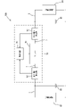
- FIG. 1 is a schematic diagram showing the configuration of a power supply system provided with an abnormality detection device of Embodiment 1.
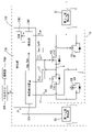
- FIG. FIG. 2 is a schematic diagram showing the configuration of the abnormality detection device of the first embodiment.
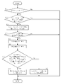
- FIG. 3 is a flow chart showing procedures in an abnormality detection method in the abnormality detection device of the first embodiment.
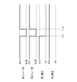
- FIG. 4 is a timing chart showing operating states of the first relay section and the second relay section and changes in the first voltage and the second voltage.
- FIG. 5 is a schematic diagram showing part of the configuration of an abnormality detection device according to another embodiment.
- FIG. 6 is a timing chart showing operating states of the first relay section and the second relay section and changes in the first voltage and the second voltage in another embodiment.
- the abnormality detection device of the present disclosure is used in a power supply system to detect an abnormality.
- the power supply system includes a first power supply section, a second power supply section, a power path that is a path for transmitting power between the first power supply section and the second power supply section, and an allowable state that allows energization of the power path. , and a relay that switches to a cut-off state that cuts off the energization of the power path.
- the abnormality detection device has a first voltage detection section, a second voltage detection section, and a detection section.
- the first voltage detection section detects a first voltage on the first power supply section side of the relay in the power path.
- the second voltage detection section detects a second voltage on the second power supply section side of the relay in the power path.
- the detector detects an abnormality based on the first voltage and the second voltage when the relay is in the cut-off state.
- the abnormality detection device of [1] above can disconnect the power path to the first power supply unit side and the second power supply unit side by turning off the relay, so that the first power supply unit and the second power supply unit can be prevented from being transmitted to the power path on the opposite side of the relay. This allows good sensing of the voltage in each of the power paths on either side of the relay.
- the abnormality detection device in [1] above has a control unit that controls the relay, and the control unit can periodically switch the relay between the allowable state and the cutoff state.
- the anomaly detection device described in [2] above is easy to detect an anomaly in detail without delay from the time an anomaly occurs in a power path.
- the abnormality detection device of [1] or [2] above has a control unit that controls the relay, and the control unit can maintain the cut-off state when the detection unit detects an abnormality.
- the abnormality detection device described in [3] above can suppress propagation of an abnormality occurring in one power path to the other power path.
- the abnormality detection device of [1] or [2] above has a control unit that controls the relay, and when the detection unit detects an abnormality, the control unit notifies the outside while maintaining the allowable state. and/or storage.
- the abnormality detection device described in [4] above maintains the relay in an allowable state to can continue to supply power to the conductive paths. Since it is configured to notify the outside, it is possible to notify a state in which power is being supplied to the one-side conductive path even though there is an abnormality in the one-side conductive path. Furthermore, by storing the state in which power is being supplied to one side of the conductive path even when there is an abnormality in the conductive path on the one side, the controller can store the occurrence of a state in which the abnormal state of the conductive path has occurred during maintenance. You can easily refer to the history.
- the abnormality detection device of any one of [2] to [4] above may have a failure detection device.
- the failure detection device detects a failure state in which the relay is maintained in an allowable state when the control unit is controlling the relay to be in the cut-off state, and a failure state in which the relay is maintained in the allowable state when the control unit is performing control to cut the relay. is maintained in a blocked state, and a normal state can be detected.
- the detection unit can detect an abnormality based on the first voltage and the second voltage when the control unit is controlling the relay to be in a cut-off state on condition that the failure detection device detects a normal state. .
- the abnormality detection device described in [5] above can distinguish between a relay failure and an abnormality in an electric power path, so that the reliability of detection of an abnormality in an electric power path in the detection unit can be further enhanced.
- the abnormality detection method of the present disclosure is used in a power supply system to detect an abnormality.
- the power supply system includes a first power supply section, a second power supply section, a power path that is a path for transmitting power between the first power supply section and the second power supply section, and an allowable state that allows energization of the power path. , and a relay that switches to a cut-off state that cuts off the energization of the power path.
- the anomaly detection method includes a first operation, a second operation, a third operation, and a fourth operation. In the first operation, the controller switches the relay to the cut-off state.
- the first voltage detection section detects a first voltage on the first power supply section side of the relay in the power path.
- the second voltage detection section detects a second voltage on the second power supply section side of the relay in the power path.
- the detection unit detects an abnormality based on the first voltage and the second voltage in the cutoff state.
- the power path can be separated to the first power supply unit side and the second power supply unit side by turning off the relay, so that the first power supply unit and the second power supply unit can be separated. can be prevented from being transmitted to the power path on the opposite side of the relay. This allows good sensing of the voltage in each of the power paths on either side of the relay.
- a first power supply section, a second power supply section, a power path that is a path for transmitting power between the first power supply section and the second power supply section, and an allowance for allowing energization of the power path A fault detection program for use in a power supply system having a state and a relay that switches to a cutoff state that cuts off energization of the power path, a first step of causing a control unit to perform an operation of switching the relay to the cut-off state; A first voltage closer to the first power supply than the relay in the power path during the interrupted state, and a second voltage closer to the second power supply than the relay in the power path during the interrupted state. and a second step of causing the detection unit to perform an operation of detecting an abnormality based on; Anomaly detection program including.
- the abnormality detection program of [7] above can disconnect the power path to the first power supply section side and the second power supply section side by turning off the relay, so that the first power supply section and the second power supply section can be separated. can be prevented from being transmitted to the power path on the opposite side of the relay. This allows good sensing of the voltage in each of the power paths on either side of the relay.
- FIG. 1 illustrates a power supply system 100 provided with an abnormality detection device 70 according to the first embodiment.
- the power supply system 100 is used as a power supply for operating the loads 92, 94, etc. of the vehicle on which it is mounted.
- the power supply system 100 includes a first power supply section 90 , a second power supply section 93 , a first conductive path 1 that is a power path, a second conductive path 2 that is a power path, a relay 10 , and an abnormality detection device 70 . .
- the first power supply section 90 and the second power supply section 93 are configured as DC power supplies such as lithium ion batteries and lead-acid batteries.
- the output voltages of the first power supply section 90 and the second power supply section 93 are, for example, 12V.
- One end of the first conductive path 1 is electrically connected to the high-potential terminal of the first power supply section 90 .
- a load 92 is electrically connected to one end of the first conducting path 1 in parallel with the first power supply section 90 .
- the other end of first conductive path 1 is electrically connected to one end of relay 10 .
- One end of the second conductive path 2 is electrically connected to the high-potential terminal of the second power supply section 93 .
- a load 94 is electrically connected to one end of the second conductive path 2 in parallel with the second power supply section 93 .
- the other end of the second conducting path 2 is electrically connected to the other end of the relay 10 .
- the first conductive path 1 and the second conductive path 2 are paths that transmit power between the first power supply section 90 and the second power supply section 93 .
- electrically connected desirably refers to a configuration in which the objects to be connected are electrically connected to each other (a state in which current can flow) so that the potentials of both objects are equal.
- electrically connected may be a configuration in which both connection objects are connected in a state in which an electric component is interposed between them and both connection objects are electrically connected.
- the load 92 has a configuration in which electrical components operate upon receiving power supply from the first power supply section 90 .
- the load 94 has the same configuration and functions as the load 92 .
- the power supply system 100 is configured as a system that can maintain the function of the load 92 by operating the load 94 instead of the load 92 when an abnormality occurs in the load 92, even when the load 92 is abnormal. ing.
- the relay 10 is arranged between the first power supply section 90 and the second power supply section 93 .
- the relay 10 switches between an allowable state in which energization of the first conductive path 1 and the second conductive path 2 is permitted, and a cutoff state in which energization of the first conductive path 1 and the second conductive path 2 is cut off.
- the relay 10 has a configuration in which a first relay section 10C and a second relay section 10F are electrically connected in parallel.
- the first relay section 10C is composed of two switch elements 10A and 10B connected in series in different directions.
- the second relay section 10F is composed of two switch elements 10D and 10E connected in series in different directions.
- each of the first relay section 10C and the second relay section 10F is composed of two N-channel MOSFETs (Metal-Oxide-Semiconductor Field Effect Transistors) will be described as a representative example.
- MOSFETs Metal-Oxide-Semiconductor Field Effect Transistors
- the sources of these switch elements 10A and 10B are electrically connected via the first intermediate conductive path 4.
- the drain of the switch element 10A is connected to the end of the first conductive path 1, and the drain of the switch element 10B is connected to the second conductive path 2.
- the first intermediate conductive path 4 is electrically connected to the failure detection device 30A via the first signal line 21. As shown in FIG.
- each of the switch elements 10D and 10E of the second relay section 10F is configured by an N-channel MOSFET
- the sources of these switch elements 10D and 10E are electrically connected via the second intermediate conductive path 5.
- the drain of the switch element 10D is connected to the end of the first conductive path 1
- the drain of the switch element 10E is connected to the second conductive path 2.
- FIG. The second intermediate conducting path 5 is electrically connected to the failure detection device 30A via the second signal line 22.
- the first relay section 10C and the second relay section 10F can have a configuration in which two MOSFETs are provided in series in a so-called butted state (a state in which the body diodes are arranged in opposite directions).
- Each gate of the switch elements 10A, 10B, 10D, and 10E is electrically connected to the control section 30. Specifically, the gates of the switch elements 10A and 10B are electrically connected to the controller 30 via the first wire 6 . Gates of the switch elements 10D and 10B are electrically connected to the control section 30 via the second wire 7 . With this configuration, the first relay section 10 ⁇ /b>C and the second relay section 10 ⁇ /b>F are configured to be individually controlled by the control section 30 .
- the abnormality detection device 70 has a first voltage detection section 50, a second voltage detection section 51, a control section 30, a failure detection device 30A, and a detection section 30B.
- the first voltage detection section 50 is provided on the first conducting path 1, which is a power path located closer to the first power supply section 90 than the relay 10 is.
- the first voltage detection unit 50 detects a first voltage V1 at a predetermined position (a position closer to the first power supply unit 90 than the relay 10) in the first conductive path 1, and detects a detection value corresponding to the first voltage V1. to section 30B.
- the detection unit 30B can identify the voltage value at the predetermined position of the first conductive path 1 based on the detection value input from the first voltage detection unit 50.
- the second voltage detection section 51 is provided on the second conducting path 2 which is a power path located on the second power supply section 93 side of the relay 10 .
- the second voltage detection unit 51 detects a second voltage V2 at a predetermined position (a position closer to the second power supply unit 93 than the relay 10) in the second conductive path 2, and detects a detection value corresponding to the second voltage V2. to section 30B.
- the detection unit 30 ⁇ /b>B can identify the voltage value at the predetermined position of the second conducting path 2 based on the detection value input from the second voltage detection unit 51 .
- the control unit 30 is mainly composed of, for example, a microcomputer, and includes an arithmetic unit such as a CPU (Central Processing Unit), a memory such as a ROM (Read Only Memory) or a RAM (Random Access Memory), an A/D converter, and the like. have.
- the control unit 30 performs on-control by giving an on-signal Son to each gate of the switch elements 10A, 10B, 10D, and 10E via the first electric wire 6 and the second electric wire 7.
- the relays 10 switch elements 10A, 10B, 10D, 10E
- the relays 10 are turned on to enter an allowable state in which conduction between the first conductive path 1 and the second conductive path 2 is permitted.
- the control unit 30 performs off control by giving an off signal Soff to each gate of the switch elements 10A, 10B, 10D, and 10E via the first wire 6 and the second wire 7.
- the relay 10 switching elements 10A, 10B, 10D, 10E
- the relay 10 does not pass current in either direction (that is, the direction toward the first conductive path 1 and the direction toward the second conductive path 2) when in the cutoff state. Electricity to the second conductive path 2 is completely cut off. That is, the controller 30 is configured to be able to control the relay 10 .
- control unit 30 is configured to periodically switch the switch elements 10A, 10B, 10D, and 10E of the relay 10 between the allowable state and the cutoff state when the relay 10 does not have a short-circuit failure or an open-circuit failure. .
- the failure detection device 30A is provided in the control section 30, for example.
- the failure detection device 30A is configured to detect failures of the switch elements 10A, 10B, 10D, and 10E in the relay 10.
- the failure detection device 30A performs a failure detection operation, for example, when a starting switch (eg, ignition switch) (not shown) is turned on.
- the failure detection device 30A acquires the third voltage V3, which is the voltage of the first intermediate conductive path 4, via the first signal line 21, and the voltage of the second intermediate conductive path 5, via the second signal line 22.
- a fourth voltage V4 is obtained.
- the failure detection device 30A detects the failure of the switch elements 10A and 10B based on the ON/OFF control state of the switch elements 10A and 10B and the third voltage V3 while turning on the switch elements 10D and 10E by the control unit 30. To detect. For example, the failure detection device 30A performs open failure detection processing for detecting open failures of the switch elements 10A and 10B based on the third voltage V3. An open failure is a failure in which a switch element does not switch from off to on.
- the failure detection device 30A It is determined that both the elements 10A and 10B have an open failure. This state is a failure state in which the relay 10 is maintained in the cut-off state while the control unit 30 is controlling the relay 10 to be in the allowable state. Thus, the failure detection device 30A detects open failures of the switch elements 10A and 10B. For example, when the fault detection device 30A detects an open fault in the switch elements 10A and 10B, it outputs an open fault signal Sop to the detector 30B.
- the failure detection device 30A When the failure detection device 30A outputs the ON signal Son from the control unit 30 to the switch elements 10A and 10B, when the third voltage V3 is the same as the voltage of the first conductive path 1 or the second conductive path 2 , the open failure of the switch elements 10A and 10B is not detected.
- This state is a normal state in which the relay 10 is maintained in the allowable state while the control unit 30 controls the relay 10 to be in the allowable state. In this case, the failure detection device 30A does not output the open failure signal Sop to the detection section 30B.
- the fault detection device 30A performs short-circuit fault detection processing for detecting short-circuit faults in the switch elements 10A and 10B based on the third voltage V3.
- a short-circuit failure is a failure in which a switch element does not switch from on to off.
- the failure detection device 30A It is determined that at least one of the switching elements 10A and 10B has a short failure.
- This state is a failure state in which the relay 10 is maintained in the allowable state while the control unit 30 is controlling the relay 10 to be in the cut-off state.
- the failure detection device 30A detects a short failure of the switch elements 10A and 10B. For example, when the failure detection device 30A detects a short failure of the switch elements 10A and 10B, it outputs a short failure signal Ssh to the detection section 30B.
- the failure detection device 30A When the failure detection device 30A outputs the off signal Soff from the control unit 30 to the switch elements 10A and 10B, when the third voltage V3 is not the same as the voltage of the first conducting path 1 or the second conducting path 2, A short failure of the switch elements 10A and 10B is not detected.
- This state is a normal state in which the relay 10 is maintained in the cut-off state while the control unit 30 performs control to set the relay 10 in the cut-off state. In this case, the failure detection device 30A does not output the short-circuit failure signal Ssh to the detection section 30B. Thus, the failure detection device 30A can detect the failure state and the normal state of the relay 10.
- the failure detection device 30A detects the failure of the switch elements 10D and 10E based on the on/off control state of the switch elements 10D and 10E and the fourth voltage V4 while turning on the switch elements 10A and 10B by the control unit 30. To detect. Since the method of detecting the failure of the switch elements 10D and 10E is the same as the method of detecting the failure of the switch elements 10A and 10B described above, the description thereof will be omitted.
- the failure detection device 30A detects a short failure of the switch elements 10D and 10E, it outputs a short failure signal Ssh to the detection unit 30B. It outputs an open failure signal Sop.
- the detection unit 30B is provided in the control unit 30, for example.
- the detection unit 30B is configured to receive the first voltage V1 in the first conductive path 1 and the second voltage V2 in the second conductive path 2 from the first voltage detection unit 50 and the second voltage detection unit 51, respectively. there is The detection unit 30B detects an abnormality based on the first voltage and the second voltage when the control unit 30 controls the relay 10 to be in the cut-off state on condition that the failure detection device 30A detects a normal state.
- the detection unit 30B detects a ground fault occurring in each of the first conductive path 1 and the second conductive path 2, and the first power supply unit from the first conductive path 1. Abnormalities such as disconnection of the second power supply section 93 from the second conductive path 2 and the like are detected.
- the detection unit 30B determines that the path is in an abnormal state (that is, an abnormality is detected). is less than the threshold, the detection unit 30B determines that the power path is in a normal state (that is, no abnormality is detected).
- the detection unit 30B detects that the power path is abnormal. status (that is, an abnormality is detected). Further, when the difference between the second voltage V2 input from the second voltage detection section 51 and the output voltage of the second power supply section 93 is less than the predetermined threshold, the detection section 30B detects that the power path is in a normal state. (that is, no abnormality is detected).
- step S1 the start switch is turned on (Yes in step S1). Then, the process proceeds to step S2, and the failure detection device 30A performs failure detection operations (open failure detection processing and short failure detection processing).
- step S1 if the start switch is not turned on (No in step S1), the process shown in FIG. 3 is terminated.
- step S2 if the fault detection device 30A does not detect the short fault and open fault of the switch elements 10A, 10B, 10D, and 10E (Yes in step S2), both the short fault signal Ssh and the open fault signal Sop are sent to the detector 30B. No output. Then, in step S3, the control unit 30 alternately outputs the ON signal Son and the OFF signal Soff to the switch elements 10A, 10B, 10D, and 10E of the relay 10 every predetermined period. to start. Thus, the control unit 30 periodically switches the relay 10 between the allowable state and the cutoff state.
- step S3 the control unit 30 periodically performs a first operation of switching the switch elements 10A, 10B, 10D, and 10E in the relay 10 to the cutoff state and an allowable operation of switching the switch elements 10A, 10B, 10D, and 10E to the allowable state.
- the first operation is a state in which the control unit 30 performs off control to output the off signal Soff to the switch elements 10A, 10B, 10D, and 10E. This cuts off the source and drain of each of the switch elements 10A, 10B, 10D, and 10E.
- the allowable operation is a state in which the control unit 30 performs on-control to output an on-signal Son to the switch elements 10A, 10B, 10D, and 10E. As a result, the source and drain of each of the switch elements 10A, 10B, 10D, and 10E are brought into an allowable state of conduction.
- step S2 when the fault detection device 30A detects a short fault in the switch elements 10A, 10B, 10D, and 10E (No in step S2), the fault detection device 30A outputs a short fault signal Ssh to the detection section 30B. do. Then, the processing in FIG. 3 ends.
- step S2 when the fault detection device 30A detects an open fault, the fault detection device 30A outputs an open fault signal Sop to the detection section 30B and ends the processing in FIG.
- the detection unit 30B does not detect an abnormality when the short-circuit failure signal Ssh or the open-circuit failure signal Sop is input.
- the detection unit 30B when the failure detection device 30A detects a short-circuit failure of the relay 10 (that is, the relay 10 turns on while being controlled to be off), the detection unit 30B does not detect an abnormality. If one of the first relay unit 10C and the second relay unit 10F has an open failure and the other does not, the detection unit 30B may detect an abnormality.
- step S4 the control unit 30 determines whether or not the first action is being executed.
- the control unit is not executing the first operation (that is, the switch elements 10A, 10B, 10D, and 10E are in a state of ON control for outputting the ON signal Son, and in step S4 If No), the process in FIG. 3 ends.
- step S4 if the control unit 30 is performing off control to output the off signal Soff to the switch elements 10A, 10B, 10D, and 10E (Yes in step S4), the process proceeds to step S5.
- the first voltage detection unit 50 performs a second operation of detecting the first voltage V1 on the first power supply unit 90 side of the first conductive path 1 rather than the relay 10 .
- the first voltage detection unit 50 detects the first voltage V1 at a predetermined position (the position closer to the first power supply unit 90 than the relay 10) in the first conductive path 1, A detection value corresponding to one voltage V1 is given to the detection section 30B.
- step S6 after the first operation, the second voltage detection unit 51 detects the second voltage V2 on the second power supply unit 93 side of the second conductive path 2 rather than the relay 10. perform an action. Specifically, in the third operation, the second voltage detection unit 51 detects the second voltage V2 at a predetermined position (position closer to the second power supply unit 93 than the relay 10) in the second conductive path 2, 2 A detection value corresponding to the voltage V2 is given to the detection unit 30B.
- step S7 the detection unit 30B detects an abnormality based on the first voltage V1 and the second voltage V2 in the cut-off state.
- a fourth operation of detecting is performed.
- step S7 the detection unit 30B detects the first state when the control unit 30 controls the relay 10 to be in the cut-off state in step S4 on condition that the failure detection device 30A detects a normal state in step S2.
- An abnormality is detected based on the voltage and the second voltage.
- step S7 the detection unit 30B determines that the difference between the first voltage V1 and the output voltage (12V) of the first power supply unit 90 is equal to or greater than a predetermined threshold, or the difference between the second voltage V2 and the output voltage (12V) of the second power supply unit 93 is ) is equal to or greater than a predetermined threshold value (Yes in step S7), the process proceeds to step S8.
- the detection unit 30B determines that the power path is in an abnormal state (that is, detects an abnormality). Then, the control unit 30 continues to output the off signal Soff to the switch elements 10A, 10B, 10D, and 10E. In other words, the control unit 30 maintains the cut-off state when the detection unit 30B detects an abnormality. Then, the processing in FIG. 3 ends.
- the detection unit 30B determines that the difference between the first voltage V1 and the output voltage of the first power supply unit 90 is less than a predetermined threshold, and the difference between the second voltage V2 and the output voltage of the second power supply unit 93 is a predetermined value. If it is determined that it is less than the threshold value (No in step S7), the process proceeds to step S9. After shifting to step S9, the detection unit 30B determines that the power path is in a normal state (that is, no abnormality is detected). Then, the control unit 30 outputs an ON signal Son to the switch elements 10A, 10B, 10D, and 10E. That is, the control unit 30 switches the relay 10 from the cutoff state to the allowable state when the detection unit 30B does not detect an abnormality in the power path. Then, the processing in FIG. 3 ends.
- the controller 30 If the failure detection device 30A does not detect any failure of the switch elements 10A, 10B, 10D, and 10E, the controller 30 outputs the ON signal Son and the OFF signal Soff to the switch elements 10A, 10B, 10D, and 10E. and , are alternately output every predetermined period.
- control unit 30 outputs signals to first relay unit 10C and second relay unit 10F (switch elements 10A, 10B, 10D, and 10E) from ON signal Son. Switch to the off signal Soff. Between time T1 and time T2, control unit 30 continues outputting off signal Soff to switch elements 10A, 10B, 10D, and 10E. From time T1 to time T2, the relay 10 is in a cutoff state in which the energization of the first conductive path 1 and the second conductive path 2 is cut off (Yes in step S4 of FIG. 3). During the period from time T1 to time T2, the detection unit 30B performs the second to fourth operations to determine whether the power path is in an abnormal state or in a normal state (steps S5 to S9 in FIG. 3). .).
- the first voltage V1 on the first conducting path 1 is the same as the output voltage (12 V) of the first power supply section 90
- the second voltage V2 on the second conducting path 2 is the second power supply. It is the same as the output voltage (12V) of the part 93 . That is, the difference between the first voltage V1 and the output voltage of the first power supply section 90 is less than the predetermined threshold, and the difference between the second voltage V2 and the output voltage of the second power supply section 93 is less than the predetermined threshold. (No in step S7 of FIG. 3). In this case, the detector 30B determines that the power path is normal (step S9 in FIG. 3).
- the control unit 30 changes the signals output to the first relay unit 10C and the second relay unit 10F (switch elements 10A, 10B, 10D, 10E) from the off signal Soff to the on signal Son. switch.
- the relay 10 is in the permissible state in which energization of the first conductive path 1 and the second conductive path 2 is permitted (No in step S4 of FIG. 3). Therefore, the second to fourth operations are not executed from time T2 to time T3. That is, the detection unit 30B does not determine whether the power path is in an abnormal state or in a normal state when it is in the allowable state.
- control unit 30 changes the signal to be output to the first relay unit 10C and the second relay unit 10F (switch elements 10A, 10B, 10D, 10E) from the ON signal Son to the OFF signal Soff. switch.
- control unit 30 continues outputting off signal Soff to switch elements 10A, 10B, 10D, and 10E.
- the relay 10 is in a cutoff state in which the first conductive path 1 and the second conductive path 2 are cut off (Yes in step S4 of FIG. 3).
- the detection unit 30B determines whether the power path is in an abnormal state or in a normal state by executing the second to fourth operations from time T3 to time T4 (steps S5 to S9 in FIG. 3). .
- the first voltage V1 in the first conductive path 1 changes from the same magnitude as the output voltage of the first power supply section 90 to 0V.
- the second voltage V2 in the second conducting path 2 is the same as the output voltage (12 V) of the second power supply section 93 and does not change.
- the difference between the first voltage V1 and the output voltage of the first power supply section 90 is greater than or equal to the predetermined threshold, and the difference between the second voltage V2 and the output voltage of the second power supply section 93 is less than the predetermined threshold. (Yes in step S7 of FIG. 3).
- the detection unit 30B determines that the power path is in an abnormal state (step S8 in FIG. 3).
- the abnormality detection device 70 detects an abnormality in the power path.
- the control unit 30 continues to output the off signal Soff to the first relay unit 10C and the second relay unit 10F (switch elements 10A, 10B, 10D, 10E). This prevents an abnormality occurring in the first conductive path 1 from propagating to the second conductive path 2 side.
- the anomaly detection device 70 of the present disclosure is used in the power supply system 100 to detect an anomaly.
- the power supply system 100 has a first power supply section 90 , a second power supply section 93 , a first conductive path 1 and a second conductive path 2 , and a relay 10 .
- the first conductive path 1 and the second conductive path 2 are paths that transmit power between the first power supply section 90 and the second power supply section 93 .
- the relay 10 switches between an allowable state in which energization of the first conductive path 1 and the second conductive path 2 is permitted, and a cutoff state in which energization of the first conductive path 1 and the second conductive path 2 is cut off.
- the abnormality detection device 70 has a first voltage detection section 50, a second voltage detection section 51, and a detection section 30B.
- the first voltage detection unit 50 detects the first voltage V1 on the first power supply unit 90 side of the first conductive path 1 and the second conductive path 2 rather than the relay 10 .
- the second voltage detection unit 51 detects a second voltage V2 on the second power supply unit 93 side of the first conductive path 1 and the second conductive path 2 rather than the relay 10 .
- Detector 30B detects an abnormality based on first voltage V1 and second voltage V2 when relay 10 is in an interrupted state.
- the first conductive path 1 and the second conductive path 2 can be separated to the first power supply section 90 side and the second power supply section 93 side by turning off the relay 10 . Therefore, it is possible to prevent the voltage of the first power supply section 90 and the second power supply section 93 from being transmitted to the power path on the opposite side of the relay 10 . Thereby, the voltage in each of the first conducting path 1 and the second conducting path 2 on both sides of the relay 10 can be detected satisfactorily.
- the abnormality detection device 70 of the present disclosure has a control unit 30 that controls the relay 10, and the control unit 30 periodically switches the relay 10 between the allowable state and the cutoff state. According to this configuration, it is easy to detect an abnormality immediately after an abnormality occurs in the first conductive path 1 and the second conductive path 2 .
- the abnormality detection device 70 of the present disclosure has the control unit 30 that controls the relay 10, and the control unit 30 maintains the cut-off state when the detection unit 30B detects an abnormality. According to this configuration, it is possible to suppress propagation of an abnormality occurring in one power path to the other power path.
- the abnormality detection device 70 of the present disclosure has a failure detection device 30A.
- the failure detection device 30A can detect a failure state and a normal state.
- the failure state is a state in which the relay 10 is maintained in an allowable state while the control unit 30 is performing control to put the relay 10 in the cut-off state.
- the normal state is a state in which the relay 10 is maintained in the cut-off state while the control unit 30 performs control to set the relay 10 in the cut-off state.
- the detection unit 30B detects the first voltage V1 and the second voltage V2 when the control unit 30 controls the relay 10 to be in the cut-off state on condition that the failure detection device 30A detects a normal state. to detect anomalies. According to this configuration, a failure of the relay 10 and an abnormality of the first conductive path 1 and the second conductive path 2 can be separated. The reliability of abnormality detection can be further improved.
- the anomaly detection method of the present disclosure is used in the power supply system 100 to detect an anomaly.
- the power supply system 100 has a first power supply section 90 , a second power supply section 93 , a first conductive path 1 and a second conductive path 2 , and a relay 10 .
- the first conductive path 1 and the second conductive path 2 are paths that transmit power between the first power supply section 90 and the second power supply section 93 .
- the relay 10 includes the first conductive path 1 and the second conductive path 2, the allowable state for allowing the energization of the first conductive path 1 and the second conductive path 2, and the energization of the first conductive path 1 and the second conductive path 2.
- the anomaly detection method includes a first operation, a second operation, a third operation, and a fourth operation.
- control unit 30 switches relay 10 to the cut-off state.
- the first voltage detection unit 50 detects the first voltage V1 on the first power supply unit 90 side of the first conductive path 1 and the second conductive path 2 rather than the relay 10 .
- the second voltage detection unit 51 detects the second voltage V2 on the second power supply unit 93 side of the first conductive path 1 and the second conductive path 2 rather than the relay 10 .
- the detection unit 30B detects an abnormality based on the first voltage V1 and the second voltage V2 in the cutoff state.
- the first conductive path 1 and the second conductive path 2 can be separated to the first power supply section 90 side and the second power supply section 93 side by setting the relay 10 to the cutoff state. Therefore, it is possible to prevent the voltage of the first power supply section 90 and the second power supply section 93 from being transmitted to the power path on the opposite side of the relay 10 . Thereby, the voltage in each of the first conducting path 1 and the second conducting path 2 on both sides of the relay 10 can be detected satisfactorily.
- the control unit 30 maintains the cut-off state when the detection unit 30B detects an abnormality, but the control unit maintains the allowable state when the detection unit detects an abnormality.
- the configuration may be such that notification to the outside and storage are performed.
- the abnormality detection device 170 transmits a notification signal N indicating that the detection unit has detected an abnormality from the control unit 130 to the external ECU 200. output to.
- the notification signal N is input to the external ECU 200
- the notification unit 200A connected to the external ECU 200 produces sound. For example, a buzzer, a speaker, or the like is used for the notification unit 200A.
- the detection unit 30B causes the RAM 130C or the like of the control unit 130 to store abnormality information M indicating that the power path has become abnormal.
- the signal output by the control unit 130 to the first relay unit 10C and the second relay unit 10F is switched from the ON signal Son to the OFF signal Soff.
- the detection section 30B determines that the power path is in an abnormal state between time T11 and time T12. discriminate.
- control unit 130 switches the signal output to first relay unit 10C and second relay unit 10F from off signal Soff to on signal Son. Then, the energization of the first conductive path 1 and the second conductive path 2 is permitted.
- a resistance component is interposed between the first conductive path 1 and the second conductive path 2 . Then, current can flow from the second conductive path 2 side to the first conductive path 1 side without dropping the second voltage V2 of the second conductive path 2 to 0V.
- the notification unit 200A can be used to notify a state in which power is being supplied to the one-side conductive path even though there is an abnormality in the one-side conductive path.
- the controller 130 stores, in its own RAM 130C or the like, abnormality information M indicating that a state in which power is being supplied to the one-side conductive path even though there is an abnormality in the one-side conductive path has occurred. , the history of abnormal conditions in the conducting path can be easily referred to during maintenance. It should be noted that only one of the output of the notification signal to the external ECU and the storage of the abnormality information in the RAM may be performed.
- the configuration in which the first relay unit 10C and the second relay unit 10F are connected in parallel has been described. , 3 or more. Further, although the first embodiment discloses that a MOSFET is used for the relay 10, a mechanical relay switch may be used for the relay.
- control unit 30 is mainly composed of a microcomputer in the first embodiment, it may be realized by a plurality of hardware circuits other than the microcomputer. Further, at least one of the failure detection device and the detection section may be provided separately from the control section.
- Embodiment 1 it is disclosed that the output voltage of the first power supply section 90 and the second power supply section 93 is 12V, but the output voltage of the first power supply section and the second power supply section is not limited to this voltage. Also, the output voltages in the first power supply section and the second power supply section may not be the same.
- the control unit 30 periodically switches the switch elements 10A, 10B, 10D, and 10E between the allowable state and the cutoff state when the relay 10 does not have a short-circuit failure or an open-circuit failure.
- the relay is not limited to this, and the relay may be periodically switched between the allowable state and the cutoff state, for example, while the vehicle is running, parked, or when the start switch is in the off state.
- the first voltage detector may perform the second operation after at least the first operation
- the second voltage detector may perform the third operation after at least the first operation
- Second intermediate conductive path 10 Relays 10A, 10B, 10D, 10E Switch element 10C First relay section 10F Second relay section 21 First signal line 22 Second signal Lines 30, 130 Control unit 30A Failure detection device 30B Detection unit 50 First voltage detection unit 51 Second voltage detection units 70, 170 Abnormality detection device 90 First power supply units 92, 94 Load 93 Second power supply unit 100...Power supply system 130C...RAM 200 External ECU 200A... reporting unit M... abnormal information N... reporting signal Sop... open failure signal Ssh... short failure signal Soff... off signal Son... on signal V1... first voltage V2... second voltage V3... third voltage V4... fourth voltage
Landscapes
- Physics & Mathematics (AREA)
- General Physics & Mathematics (AREA)
- Emergency Protection Circuit Devices (AREA)
- Protection Of Static Devices (AREA)
- Testing Of Short-Circuits, Discontinuities, Leakage, Or Incorrect Line Connections (AREA)
Abstract
Description
第1電源部と、第2電源部と、前記第1電源部と前記第2電源部との間で電力を伝送する経路である電力路と、前記電力路の通電を許容する許容状態と、前記電力路の通電を遮断する遮断状態とに切り替わるリレーと、を有する電源システムに用いられ、異常を検出する異常検出装置であって、
前記電力路における前記リレーよりも前記第1電源部側の第1電圧を検出する第1電圧検出部と、
前記電力路における前記リレーよりも前記第2電源部側の第2電圧を検出する第2電圧検出部と、
前記リレーが前記遮断状態のときの前記第1電圧と前記第2電圧とに基づいて異常を検出する検出部と、
を有する。 An abnormality detection device that is one of the present disclosure includes:
a first power supply unit, a second power supply unit, a power path that is a path for transmitting power between the first power supply unit and the second power supply unit, and an allowable state that allows energization of the power path; An abnormality detection device for detecting an abnormality, which is used in a power supply system having a relay that switches to a cutoff state that cuts off the energization of the electric power path,
a first voltage detection unit that detects a first voltage on the first power supply unit side of the relay in the power path;
a second voltage detection unit that detects a second voltage on the second power supply unit side of the relay in the power path;
a detection unit that detects an abnormality based on the first voltage and the second voltage when the relay is in the cut-off state;
have
第1電源部と、第2電源部と、前記第1電源部と前記第2電源部との間で電力を伝送する経路である電力路と、前記電力路の通電を許容する許容状態と、前記電力路の通電を遮断する遮断状態とに切り替わるリレーと、を有する電源システムに用いられ、異常を検出する異常検出方法であって、
制御部が、リレーを前記遮断状態に切り替える第1動作と、
少なくとも前記第1動作の後、第1電圧検出部が、前記電力路における前記リレーよりも前記第1電源部側の第1電圧を検出する第2動作と、
少なくとも前記第1動作の後、第2電圧検出部が、前記電力路における前記リレーよりも前記第2電源部側の第2電圧を検出する第3動作と、
前記第2動作と、前記第3動作とが実行された後、検出部が、前記遮断状態のときの前記第1電圧と前記第2電圧とに基づいて異常を検出する第4動作と、
を含む。 An anomaly detection method that is one of the present disclosure includes:
a first power supply unit, a second power supply unit, a power path that is a path for transmitting power between the first power supply unit and the second power supply unit, and an allowable state that allows energization of the power path; An abnormality detection method for detecting an abnormality, which is used in a power supply system having a relay that switches to a cutoff state that cuts off the energization of the electric power path,
A first operation in which the control unit switches the relay to the cutoff state;
a second operation in which, after at least the first operation, a first voltage detection unit detects a first voltage on the power path closer to the first power supply unit than the relay;
a third operation in which, after at least the first operation, a second voltage detection unit detects a second voltage on the second power supply unit side of the relay in the power path;
a fourth operation in which, after the second operation and the third operation are performed, the detection unit detects an abnormality based on the first voltage and the second voltage in the cutoff state;
including.
前記リレーを前記遮断状態に切り替える動作を制御部に行わせる第1ステップと、
前記遮断状態の期間の前記電力路における前記リレーよりも前記第1電源部側の第1電圧と、前記遮断状態の期間の前記電力路における前記リレーよりも前記第2電源部側の第2電圧と、に基づいて異常を検出する動作を検出部に行わせる第2ステップと、
を含む異常検出プログラム。 [7] A first power supply section, a second power supply section, a power path that is a path for transmitting power between the first power supply section and the second power supply section, and an allowance for allowing energization of the power path A fault detection program for use in a power supply system having a state and a relay that switches to a cutoff state that cuts off energization of the power path,
a first step of causing a control unit to perform an operation of switching the relay to the cut-off state;
A first voltage closer to the first power supply than the relay in the power path during the interrupted state, and a second voltage closer to the second power supply than the relay in the power path during the interrupted state. and a second step of causing the detection unit to perform an operation of detecting an abnormality based on;
Anomaly detection program including.
〔電源システムの構成〕
図1には、実施形態1に係る異常検出装置70が設けられた電源システム100が例示される。電源システム100は、搭載された車両の負荷92,94等を動作させる電源として使用される。電源システム100は、第1電源部90、第2電源部93、電力路である第1導電路1、電力路である第2導電路2、リレー10、及び異常検出装置70を有している。 <Embodiment 1>
[Configuration of power supply system]
FIG. 1 illustrates a
異常検出装置70は、第1電圧検出部50、第2電圧検出部51、制御部30、故障検出装置30A、及び検出部30Bを有している。 [Configuration of anomaly detection device]
The
異常検出装置70が異常を検出する異常検出方法の一例について説明する。 [Operation in anomaly detection device]
An example of an abnormality detection method for detecting an abnormality by the
異常検出装置70における動作の一例を図4等を参照しつつ説明する。 [Example of operation in anomaly detection device]
An example of the operation of the
2…第2導電路(電力路)
4…第1中間導電路
5…第2中間導電路
10…リレー
10A,10B,10D,10E…スイッチ素子
10C…第1リレー部
10F…第2リレー部
21…第1信号線
22…第2信号線
30,130…制御部
30A…故障検出装置
30B…検出部
50…第1電圧検出部
51…第2電圧検出部
70,170…異常検出装置
90…第1電源部
92,94…負荷
93…第2電源部
100…電源システム
130C…RAM
200…外部ECU
200A…報知部
M…異常情報
N…報知信号
Sop…オープン故障信号
Ssh…ショート故障信号
Soff…オフ信号
Son…オン信号
V1…第1電圧
V2…第2電圧
V3…第3電圧
V4…第4電圧 1... First conductive path (power path)
2 ... second conductive path (power path)
4 First intermediate
200 External ECU
200A... reporting unit M... abnormal information N... reporting signal Sop... open failure signal Ssh... short failure signal Soff... off signal Son... on signal V1... first voltage V2... second voltage V3... third voltage V4... fourth voltage
Claims (6)
- 第1電源部と、第2電源部と、前記第1電源部と前記第2電源部との間で電力を伝送する経路である電力路と、前記電力路の通電を許容する許容状態と、前記電力路の通電を遮断する遮断状態とに切り替わるリレーと、を有する電源システムに用いられ、異常を検出する異常検出装置であって、
前記電力路における前記リレーよりも前記第1電源部側の第1電圧を検出する第1電圧検出部と、
前記電力路における前記リレーよりも前記第2電源部側の第2電圧を検出する第2電圧検出部と、
前記リレーが前記遮断状態のときの前記第1電圧と前記第2電圧とに基づいて異常を検出する検出部と、
を有する異常検出装置。 a first power supply unit, a second power supply unit, a power path that is a path for transmitting power between the first power supply unit and the second power supply unit, and an allowable state that allows energization of the power path; An abnormality detection device for detecting an abnormality, which is used in a power supply system having a relay that switches to a cutoff state that cuts off the energization of the electric power path,
a first voltage detection unit that detects a first voltage on the first power supply unit side of the relay in the power path;
a second voltage detection unit that detects a second voltage on the second power supply unit side of the relay in the power path;
a detection unit that detects an abnormality based on the first voltage and the second voltage when the relay is in the cut-off state;
An anomaly detection device having - 前記リレーを制御する制御部を有し、
前記制御部は、前記リレーを周期的に前記許容状態と前記遮断状態とに切り替える請求項1に記載の異常検出装置。 Having a control unit that controls the relay,
The abnormality detection device according to claim 1, wherein the control unit periodically switches the relay between the allowable state and the cutoff state. - 前記リレーを制御する制御部を有し、
前記制御部は、前記検出部が異常を検出した場合に前記遮断状態を維持する請求項1又は請求項2に記載の異常検出装置。 Having a control unit that controls the relay,
3. The abnormality detection device according to claim 1, wherein the control section maintains the cut-off state when the detection section detects an abnormality. - 前記リレーを制御する制御部を有し、
前記制御部は、前記検出部が異常を検出した場合、前記許容状態を維持しつつ外部への報知又は記憶の少なくともいずれかを行う請求項1又は請求項2に記載の異常検出装置。 Having a control unit that controls the relay,
3. The abnormality detection device according to claim 1, wherein when the detection section detects an abnormality, the control section performs at least one of external notification and storage while maintaining the allowable state. - 前記制御部が前記リレーを前記遮断状態にする制御を行っているときに前記リレーが前記許容状態で維持される故障状態と、前記制御部が前記リレーを前記遮断状態にする制御を行っているときに前記リレーが前記遮断状態で維持される正常状態と、を検出可能な故障検出装置を有し、
前記検出部は、前記故障検出装置が前記正常状態を検出することを条件として、前記制御部が前記リレーを前記遮断状態にする制御を行っているときの前記第1電圧と前記第2電圧とに基づいて異常を検出する請求項2から請求項4のいずれか1項に記載の異常検出装置。 a failure state in which the relay is maintained in the allowable state while the control unit is controlling the relay to be in the cut-off state; and a failure state in which the relay is maintained in the cut-off state by the control unit. a failure detection device capable of detecting a normal state in which the relay is maintained in the cut-off state;
The detection unit detects the first voltage and the second voltage when the control unit is controlling the relay to be in the cut-off state on condition that the failure detection device detects the normal state. 5. The abnormality detection device according to any one of claims 2 to 4, wherein the abnormality is detected based on. - 第1電源部と、第2電源部と、前記第1電源部と前記第2電源部との間で電力を伝送する経路である電力路と、前記電力路の通電を許容する許容状態と、前記電力路の通電を遮断する遮断状態とに切り替わるリレーと、を有する電源システムに用いられ、異常を検出する異常検出方法であって、
制御部が、前記リレーを前記遮断状態に切り替える第1動作と、
少なくとも前記第1動作の後、第1電圧検出部が、前記電力路における前記リレーよりも前記第1電源部側の第1電圧を検出する第2動作と、
少なくとも前記第1動作の後、第2電圧検出部が、前記電力路における前記リレーよりも前記第2電源部側の第2電圧を検出する第3動作と、
前記第2動作と、前記第3動作とが実行された後、検出部が、前記遮断状態のときの前記第1電圧と前記第2電圧とに基づいて異常を検出する第4動作と、
を含む異常検出方法。 a first power supply unit, a second power supply unit, a power path that is a path for transmitting power between the first power supply unit and the second power supply unit, and an allowable state that allows energization of the power path; An abnormality detection method for detecting an abnormality, which is used in a power supply system having a relay that switches to a cutoff state that cuts off the energization of the electric power path,
A first operation in which the control unit switches the relay to the cut-off state;
a second operation in which, after at least the first operation, a first voltage detection unit detects a first voltage on the power path closer to the first power supply unit than the relay;
a third operation in which, after at least the first operation, a second voltage detection unit detects a second voltage on the second power supply unit side of the relay in the power path;
a fourth operation in which, after the second operation and the third operation are performed, the detection unit detects an abnormality based on the first voltage and the second voltage in the cutoff state;
anomaly detection methods including;
Priority Applications (3)
| Application Number | Priority Date | Filing Date | Title |
|---|---|---|---|
| US18/552,170 US20240183911A1 (en) | 2021-03-25 | 2022-03-10 | Anomaly detection apparatus and anomaly detection method |
| DE112022001738.4T DE112022001738T5 (en) | 2021-03-25 | 2022-03-10 | Device and method for detecting anomalies |
| CN202280022861.2A CN117044058A (en) | 2021-03-25 | 2022-03-10 | Abnormality detection device and abnormality detection method |
Applications Claiming Priority (2)
| Application Number | Priority Date | Filing Date | Title |
|---|---|---|---|
| JP2021051023A JP2022149070A (en) | 2021-03-25 | 2021-03-25 | Abnormality detection device and abnormality detection method |
| JP2021-051023 | 2021-03-25 |
Publications (1)
| Publication Number | Publication Date |
|---|---|
| WO2022202350A1 true WO2022202350A1 (en) | 2022-09-29 |
Family
ID=83394934
Family Applications (1)
| Application Number | Title | Priority Date | Filing Date |
|---|---|---|---|
| PCT/JP2022/010466 WO2022202350A1 (en) | 2021-03-25 | 2022-03-10 | Abnormality detection device, and abnormality detection method |
Country Status (5)
| Country | Link |
|---|---|
| US (1) | US20240183911A1 (en) |
| JP (1) | JP2022149070A (en) |
| CN (1) | CN117044058A (en) |
| DE (1) | DE112022001738T5 (en) |
| WO (1) | WO2022202350A1 (en) |
Families Citing this family (1)
| Publication number | Priority date | Publication date | Assignee | Title |
|---|---|---|---|---|
| US20240170944A1 (en) * | 2022-11-18 | 2024-05-23 | Abb Schweiz Ag | Ground fault protection in a high resistance grounding system |
Citations (3)
| Publication number | Priority date | Publication date | Assignee | Title |
|---|---|---|---|---|
| JP2017216790A (en) * | 2016-05-31 | 2017-12-07 | 株式会社オートネットワーク技術研究所 | Relay device and power supply unit |
| JP2018006252A (en) * | 2016-07-07 | 2018-01-11 | 株式会社オートネットワーク技術研究所 | Relay device |
| JP2019062622A (en) * | 2017-09-26 | 2019-04-18 | 株式会社デンソーテン | Control device and failure determination method |
Family Cites Families (3)
| Publication number | Priority date | Publication date | Assignee | Title |
|---|---|---|---|---|
| CN107112744B (en) | 2014-12-24 | 2019-04-26 | 株式会社杰士汤浅国际 | Apparatus for protecting power supply, power supply device and fault diagnosis method for switch |
| JP2018129951A (en) | 2017-02-09 | 2018-08-16 | 株式会社オートネットワーク技術研究所 | Abnormality detector of on-vehicle power supply device, and on-vehicle power supply device |
| JP2019083393A (en) | 2017-10-30 | 2019-05-30 | 矢崎総業株式会社 | Semiconductor relay failure detection device |
-
2021
- 2021-03-25 JP JP2021051023A patent/JP2022149070A/en active Pending
-
2022
- 2022-03-10 US US18/552,170 patent/US20240183911A1/en active Pending
- 2022-03-10 CN CN202280022861.2A patent/CN117044058A/en active Pending
- 2022-03-10 DE DE112022001738.4T patent/DE112022001738T5/en active Pending
- 2022-03-10 WO PCT/JP2022/010466 patent/WO2022202350A1/en active Application Filing
Patent Citations (3)
| Publication number | Priority date | Publication date | Assignee | Title |
|---|---|---|---|---|
| JP2017216790A (en) * | 2016-05-31 | 2017-12-07 | 株式会社オートネットワーク技術研究所 | Relay device and power supply unit |
| JP2018006252A (en) * | 2016-07-07 | 2018-01-11 | 株式会社オートネットワーク技術研究所 | Relay device |
| JP2019062622A (en) * | 2017-09-26 | 2019-04-18 | 株式会社デンソーテン | Control device and failure determination method |
Also Published As
| Publication number | Publication date |
|---|---|
| DE112022001738T5 (en) | 2024-01-11 |
| US20240183911A1 (en) | 2024-06-06 |
| CN117044058A (en) | 2023-11-10 |
| JP2022149070A (en) | 2022-10-06 |
Similar Documents
| Publication | Publication Date | Title |
|---|---|---|
| CN108604516B (en) | Relay device | |
| JP4643419B2 (en) | Load drive device with self-diagnosis function | |
| JP6623937B2 (en) | Relay device and power supply device | |
| JP5526965B2 (en) | Power supply control device and failure detection method | |
| US10804714B2 (en) | Relay device and in-vehicle system | |
| WO2022244687A1 (en) | Blocking control device and blocking control system | |
| CN107765073B (en) | Overcurrent detection device, power storage device, and current detection method | |
| WO2017195671A1 (en) | Relay device | |
| JP2018148726A (en) | Protection circuit for on-vehicle battery | |
| WO2022202350A1 (en) | Abnormality detection device, and abnormality detection method | |
| US20200195016A1 (en) | Precharge controller | |
| WO2019044573A1 (en) | Connection unit and power source system | |
| CN112444720B (en) | Detection circuit and detection method of electric control device | |
| JP2012016094A (en) | Feeding controller and feeding control method | |
| JP7416027B2 (en) | Vehicle power system | |
| WO2017159307A1 (en) | Power supply box | |
| JP7530556B2 (en) | Earth fault detection device | |
| WO2022059370A1 (en) | Drive device | |
| CN220291898U (en) | Motor controller, vehicle braking system and electric automobile | |
| KR102477497B1 (en) | Short circuit fault detection method of vehicle ontroller | |
| WO2024013842A1 (en) | Shut-off device for vehicle | |
| WO2024185230A1 (en) | Power distribution device and wire-disconnect determination method | |
| WO2023152786A1 (en) | On-vehicle shutoff control device | |
| JP5394868B2 (en) | Inrush current prevention device and inrush current prevention device short circuit diagnosis method | |
| KR20160135422A (en) | Lamp driving system and method of vehicle |
Legal Events
| Date | Code | Title | Description |
|---|---|---|---|
| 121 | Ep: the epo has been informed by wipo that ep was designated in this application |
Ref document number: 22775142 Country of ref document: EP Kind code of ref document: A1 |
|
| WWE | Wipo information: entry into national phase |
Ref document number: 202280022861.2 Country of ref document: CN |
|
| WWE | Wipo information: entry into national phase |
Ref document number: 18552170 Country of ref document: US |
|
| WWE | Wipo information: entry into national phase |
Ref document number: 112022001738 Country of ref document: DE |
|
| 122 | Ep: pct application non-entry in european phase |
Ref document number: 22775142 Country of ref document: EP Kind code of ref document: A1 |