JP7416027B2 - Vehicle power system - Google Patents
Vehicle power system Download PDFInfo
- Publication number
- JP7416027B2 JP7416027B2 JP2021136438A JP2021136438A JP7416027B2 JP 7416027 B2 JP7416027 B2 JP 7416027B2 JP 2021136438 A JP2021136438 A JP 2021136438A JP 2021136438 A JP2021136438 A JP 2021136438A JP 7416027 B2 JP7416027 B2 JP 7416027B2
- Authority
- JP
- Japan
- Prior art keywords
- switch
- battery
- unit
- storage battery
- electric load
- Prior art date
- Legal status (The legal status is an assumption and is not a legal conclusion. Google has not performed a legal analysis and makes no representation as to the accuracy of the status listed.)
- Active
Links
- 238000001514 detection method Methods 0.000 claims description 103
- 230000005856 abnormality Effects 0.000 claims description 48
- 238000004891 communication Methods 0.000 claims description 43
- 238000010248 power generation Methods 0.000 claims description 13
- 239000003990 capacitor Substances 0.000 claims description 8
- 238000007599 discharging Methods 0.000 claims description 3
- 230000005611 electricity Effects 0.000 claims 3
- 238000000034 method Methods 0.000 description 11
- 102100029469 WD repeat and HMG-box DNA-binding protein 1 Human genes 0.000 description 9
- 101710097421 WD repeat and HMG-box DNA-binding protein 1 Proteins 0.000 description 9
- 238000010586 diagram Methods 0.000 description 7
- 230000000694 effects Effects 0.000 description 7
- 230000004048 modification Effects 0.000 description 7
- 238000012986 modification Methods 0.000 description 7
- 238000012545 processing Methods 0.000 description 6
- 230000008569 process Effects 0.000 description 5
- 239000000758 substrate Substances 0.000 description 3
- 230000002159 abnormal effect Effects 0.000 description 2
- 230000006870 function Effects 0.000 description 2
- 230000007257 malfunction Effects 0.000 description 2
- 230000007246 mechanism Effects 0.000 description 2
- 230000004044 response Effects 0.000 description 2
- HBBGRARXTFLTSG-UHFFFAOYSA-N Lithium ion Chemical compound [Li+] HBBGRARXTFLTSG-UHFFFAOYSA-N 0.000 description 1
- PXHVJJICTQNCMI-UHFFFAOYSA-N Nickel Chemical compound [Ni] PXHVJJICTQNCMI-UHFFFAOYSA-N 0.000 description 1
- 230000000903 blocking effect Effects 0.000 description 1
- 238000009413 insulation Methods 0.000 description 1
- 229910001416 lithium ion Inorganic materials 0.000 description 1
- 238000012423 maintenance Methods 0.000 description 1
- 229910000652 nickel hydride Inorganic materials 0.000 description 1
- 238000005070 sampling Methods 0.000 description 1
Images


Classifications
-
- B—PERFORMING OPERATIONS; TRANSPORTING
- B60—VEHICLES IN GENERAL
- B60L—PROPULSION OF ELECTRICALLY-PROPELLED VEHICLES; SUPPLYING ELECTRIC POWER FOR AUXILIARY EQUIPMENT OF ELECTRICALLY-PROPELLED VEHICLES; ELECTRODYNAMIC BRAKE SYSTEMS FOR VEHICLES IN GENERAL; MAGNETIC SUSPENSION OR LEVITATION FOR VEHICLES; MONITORING OPERATING VARIABLES OF ELECTRICALLY-PROPELLED VEHICLES; ELECTRIC SAFETY DEVICES FOR ELECTRICALLY-PROPELLED VEHICLES
- B60L58/00—Methods or circuit arrangements for monitoring or controlling batteries or fuel cells, specially adapted for electric vehicles
- B60L58/10—Methods or circuit arrangements for monitoring or controlling batteries or fuel cells, specially adapted for electric vehicles for monitoring or controlling batteries
- B60L58/18—Methods or circuit arrangements for monitoring or controlling batteries or fuel cells, specially adapted for electric vehicles for monitoring or controlling batteries of two or more battery modules
- B60L58/19—Switching between serial connection and parallel connection of battery modules
-
- B—PERFORMING OPERATIONS; TRANSPORTING
- B60—VEHICLES IN GENERAL
- B60L—PROPULSION OF ELECTRICALLY-PROPELLED VEHICLES; SUPPLYING ELECTRIC POWER FOR AUXILIARY EQUIPMENT OF ELECTRICALLY-PROPELLED VEHICLES; ELECTRODYNAMIC BRAKE SYSTEMS FOR VEHICLES IN GENERAL; MAGNETIC SUSPENSION OR LEVITATION FOR VEHICLES; MONITORING OPERATING VARIABLES OF ELECTRICALLY-PROPELLED VEHICLES; ELECTRIC SAFETY DEVICES FOR ELECTRICALLY-PROPELLED VEHICLES
- B60L3/00—Electric devices on electrically-propelled vehicles for safety purposes; Monitoring operating variables, e.g. speed, deceleration or energy consumption
- B60L3/0023—Detecting, eliminating, remedying or compensating for drive train abnormalities, e.g. failures within the drive train
- B60L3/0046—Detecting, eliminating, remedying or compensating for drive train abnormalities, e.g. failures within the drive train relating to electric energy storage systems, e.g. batteries or capacitors
-
- B—PERFORMING OPERATIONS; TRANSPORTING
- B60—VEHICLES IN GENERAL
- B60L—PROPULSION OF ELECTRICALLY-PROPELLED VEHICLES; SUPPLYING ELECTRIC POWER FOR AUXILIARY EQUIPMENT OF ELECTRICALLY-PROPELLED VEHICLES; ELECTRODYNAMIC BRAKE SYSTEMS FOR VEHICLES IN GENERAL; MAGNETIC SUSPENSION OR LEVITATION FOR VEHICLES; MONITORING OPERATING VARIABLES OF ELECTRICALLY-PROPELLED VEHICLES; ELECTRIC SAFETY DEVICES FOR ELECTRICALLY-PROPELLED VEHICLES
- B60L3/00—Electric devices on electrically-propelled vehicles for safety purposes; Monitoring operating variables, e.g. speed, deceleration or energy consumption
- B60L3/0023—Detecting, eliminating, remedying or compensating for drive train abnormalities, e.g. failures within the drive train
- B60L3/0084—Detecting, eliminating, remedying or compensating for drive train abnormalities, e.g. failures within the drive train relating to control modules
-
- B—PERFORMING OPERATIONS; TRANSPORTING
- B60—VEHICLES IN GENERAL
- B60L—PROPULSION OF ELECTRICALLY-PROPELLED VEHICLES; SUPPLYING ELECTRIC POWER FOR AUXILIARY EQUIPMENT OF ELECTRICALLY-PROPELLED VEHICLES; ELECTRODYNAMIC BRAKE SYSTEMS FOR VEHICLES IN GENERAL; MAGNETIC SUSPENSION OR LEVITATION FOR VEHICLES; MONITORING OPERATING VARIABLES OF ELECTRICALLY-PROPELLED VEHICLES; ELECTRIC SAFETY DEVICES FOR ELECTRICALLY-PROPELLED VEHICLES
- B60L3/00—Electric devices on electrically-propelled vehicles for safety purposes; Monitoring operating variables, e.g. speed, deceleration or energy consumption
- B60L3/04—Cutting off the power supply under fault conditions
-
- B—PERFORMING OPERATIONS; TRANSPORTING
- B60—VEHICLES IN GENERAL
- B60L—PROPULSION OF ELECTRICALLY-PROPELLED VEHICLES; SUPPLYING ELECTRIC POWER FOR AUXILIARY EQUIPMENT OF ELECTRICALLY-PROPELLED VEHICLES; ELECTRODYNAMIC BRAKE SYSTEMS FOR VEHICLES IN GENERAL; MAGNETIC SUSPENSION OR LEVITATION FOR VEHICLES; MONITORING OPERATING VARIABLES OF ELECTRICALLY-PROPELLED VEHICLES; ELECTRIC SAFETY DEVICES FOR ELECTRICALLY-PROPELLED VEHICLES
- B60L58/00—Methods or circuit arrangements for monitoring or controlling batteries or fuel cells, specially adapted for electric vehicles
- B60L58/10—Methods or circuit arrangements for monitoring or controlling batteries or fuel cells, specially adapted for electric vehicles for monitoring or controlling batteries
- B60L58/12—Methods or circuit arrangements for monitoring or controlling batteries or fuel cells, specially adapted for electric vehicles for monitoring or controlling batteries responding to state of charge [SoC]
-
- B—PERFORMING OPERATIONS; TRANSPORTING
- B60—VEHICLES IN GENERAL
- B60R—VEHICLES, VEHICLE FITTINGS, OR VEHICLE PARTS, NOT OTHERWISE PROVIDED FOR
- B60R16/00—Electric or fluid circuits specially adapted for vehicles and not otherwise provided for; Arrangement of elements of electric or fluid circuits specially adapted for vehicles and not otherwise provided for
- B60R16/02—Electric or fluid circuits specially adapted for vehicles and not otherwise provided for; Arrangement of elements of electric or fluid circuits specially adapted for vehicles and not otherwise provided for electric constitutive elements
- B60R16/03—Electric or fluid circuits specially adapted for vehicles and not otherwise provided for; Arrangement of elements of electric or fluid circuits specially adapted for vehicles and not otherwise provided for electric constitutive elements for supply of electrical power to vehicle subsystems or for
-
- H—ELECTRICITY
- H02—GENERATION; CONVERSION OR DISTRIBUTION OF ELECTRIC POWER
- H02H—EMERGENCY PROTECTIVE CIRCUIT ARRANGEMENTS
- H02H7/00—Emergency protective circuit arrangements specially adapted for specific types of electric machines or apparatus or for sectionalised protection of cable or line systems, and effecting automatic switching in the event of an undesired change from normal working conditions
- H02H7/18—Emergency protective circuit arrangements specially adapted for specific types of electric machines or apparatus or for sectionalised protection of cable or line systems, and effecting automatic switching in the event of an undesired change from normal working conditions for batteries; for accumulators
-
- H—ELECTRICITY
- H02—GENERATION; CONVERSION OR DISTRIBUTION OF ELECTRIC POWER
- H02J—CIRCUIT ARRANGEMENTS OR SYSTEMS FOR SUPPLYING OR DISTRIBUTING ELECTRIC POWER; SYSTEMS FOR STORING ELECTRIC ENERGY
- H02J7/00—Circuit arrangements for charging or depolarising batteries or for supplying loads from batteries
- H02J7/0013—Circuit arrangements for charging or depolarising batteries or for supplying loads from batteries acting upon several batteries simultaneously or sequentially
- H02J7/0024—Parallel/serial switching of connection of batteries to charge or load circuit
-
- H—ELECTRICITY
- H02—GENERATION; CONVERSION OR DISTRIBUTION OF ELECTRIC POWER
- H02J—CIRCUIT ARRANGEMENTS OR SYSTEMS FOR SUPPLYING OR DISTRIBUTING ELECTRIC POWER; SYSTEMS FOR STORING ELECTRIC ENERGY
- H02J7/00—Circuit arrangements for charging or depolarising batteries or for supplying loads from batteries
- H02J7/0029—Circuit arrangements for charging or depolarising batteries or for supplying loads from batteries with safety or protection devices or circuits
- H02J7/00304—Overcurrent protection
-
- H—ELECTRICITY
- H02—GENERATION; CONVERSION OR DISTRIBUTION OF ELECTRIC POWER
- H02J—CIRCUIT ARRANGEMENTS OR SYSTEMS FOR SUPPLYING OR DISTRIBUTING ELECTRIC POWER; SYSTEMS FOR STORING ELECTRIC ENERGY
- H02J7/00—Circuit arrangements for charging or depolarising batteries or for supplying loads from batteries
- H02J7/0047—Circuit arrangements for charging or depolarising batteries or for supplying loads from batteries with monitoring or indicating devices or circuits
- H02J7/0048—Detection of remaining charge capacity or state of charge [SOC]
-
- H—ELECTRICITY
- H02—GENERATION; CONVERSION OR DISTRIBUTION OF ELECTRIC POWER
- H02J—CIRCUIT ARRANGEMENTS OR SYSTEMS FOR SUPPLYING OR DISTRIBUTING ELECTRIC POWER; SYSTEMS FOR STORING ELECTRIC ENERGY
- H02J7/00—Circuit arrangements for charging or depolarising batteries or for supplying loads from batteries
- H02J7/0063—Circuit arrangements for charging or depolarising batteries or for supplying loads from batteries with circuits adapted for supplying loads from the battery
-
- H—ELECTRICITY
- H02—GENERATION; CONVERSION OR DISTRIBUTION OF ELECTRIC POWER
- H02J—CIRCUIT ARRANGEMENTS OR SYSTEMS FOR SUPPLYING OR DISTRIBUTING ELECTRIC POWER; SYSTEMS FOR STORING ELECTRIC ENERGY
- H02J7/00—Circuit arrangements for charging or depolarising batteries or for supplying loads from batteries
- H02J7/007—Regulation of charging or discharging current or voltage
- H02J7/00712—Regulation of charging or discharging current or voltage the cycle being controlled or terminated in response to electric parameters
-
- H—ELECTRICITY
- H02—GENERATION; CONVERSION OR DISTRIBUTION OF ELECTRIC POWER
- H02J—CIRCUIT ARRANGEMENTS OR SYSTEMS FOR SUPPLYING OR DISTRIBUTING ELECTRIC POWER; SYSTEMS FOR STORING ELECTRIC ENERGY
- H02J7/00—Circuit arrangements for charging or depolarising batteries or for supplying loads from batteries
- H02J7/34—Parallel operation in networks using both storage and other DC sources, e.g. providing buffering
- H02J7/345—Parallel operation in networks using both storage and other DC sources, e.g. providing buffering using capacitors as storage or buffering devices
-
- B—PERFORMING OPERATIONS; TRANSPORTING
- B60—VEHICLES IN GENERAL
- B60L—PROPULSION OF ELECTRICALLY-PROPELLED VEHICLES; SUPPLYING ELECTRIC POWER FOR AUXILIARY EQUIPMENT OF ELECTRICALLY-PROPELLED VEHICLES; ELECTRODYNAMIC BRAKE SYSTEMS FOR VEHICLES IN GENERAL; MAGNETIC SUSPENSION OR LEVITATION FOR VEHICLES; MONITORING OPERATING VARIABLES OF ELECTRICALLY-PROPELLED VEHICLES; ELECTRIC SAFETY DEVICES FOR ELECTRICALLY-PROPELLED VEHICLES
- B60L2240/00—Control parameters of input or output; Target parameters
- B60L2240/40—Drive Train control parameters
- B60L2240/54—Drive Train control parameters related to batteries
- B60L2240/549—Current
-
- Y—GENERAL TAGGING OF NEW TECHNOLOGICAL DEVELOPMENTS; GENERAL TAGGING OF CROSS-SECTIONAL TECHNOLOGIES SPANNING OVER SEVERAL SECTIONS OF THE IPC; TECHNICAL SUBJECTS COVERED BY FORMER USPC CROSS-REFERENCE ART COLLECTIONS [XRACs] AND DIGESTS
- Y02—TECHNOLOGIES OR APPLICATIONS FOR MITIGATION OR ADAPTATION AGAINST CLIMATE CHANGE
- Y02E—REDUCTION OF GREENHOUSE GAS [GHG] EMISSIONS, RELATED TO ENERGY GENERATION, TRANSMISSION OR DISTRIBUTION
- Y02E60/00—Enabling technologies; Technologies with a potential or indirect contribution to GHG emissions mitigation
- Y02E60/10—Energy storage using batteries
Landscapes
- Engineering & Computer Science (AREA)
- Power Engineering (AREA)
- Mechanical Engineering (AREA)
- Life Sciences & Earth Sciences (AREA)
- Sustainable Development (AREA)
- Sustainable Energy (AREA)
- Transportation (AREA)
- Charge And Discharge Circuits For Batteries Or The Like (AREA)
- Protection Of Static Devices (AREA)
- Secondary Cells (AREA)
Description
本発明は、車両用電源システムに関する。 The present invention relates to a vehicle power supply system.
従来、蓄電池の状態(電圧、電流、地絡など)を検出するセンサユニットと、センサユニットから検出結果を受信し、受信した検出結果に基づいて蓄電池と電気負荷(回転電機などの発電機を含む)との間における通電及び通電遮断を切り替えるリレースイッチのオンオフを制御するECUと、を備えた電源システムについて知られている(例えば、特許文献1)。 Conventionally, a sensor unit that detects the status of a storage battery (voltage, current, ground fault, etc.) receives detection results from the sensor unit, and based on the received detection results, it detects the storage battery and electrical loads (including generators such as rotating electric machines). ) and an ECU that controls on/off of a relay switch that switches between energization and energization cutoff (for example, Patent Document 1).
ところで、特許文献1のような電源システムの場合、センサユニットとECUとの間の通信が不可能となった場合、蓄電池の過放電、過充電を防止するため、リレースイッチをオフして、蓄電池と電気負荷との通電を遮断して安全を確保するのが一般的である。
By the way, in the case of a power supply system like
しかしながら、電気自動車のように、回転電機を主機とする場合、蓄電池からの電力供給が途絶えると、電気自動車は、即停止につながるという問題があった。 However, when an electric vehicle uses a rotating electrical machine as its main engine, there is a problem in that if the power supply from the storage battery is cut off, the electric vehicle immediately stops.
本発明は、上記課題に鑑みてなされたものであり、その目的は、通信が途絶えてもしばらくの間、蓄電池からの電力供給を可能とする車両用電源システムを提供することにある。 The present invention has been made in view of the above problems, and an object of the present invention is to provide a vehicle power supply system that allows power to be supplied from a storage battery for a while even if communication is interrupted.
上記課題を解決するための第1の手段は、電気負荷に対して電力を供給可能な蓄電池の電池状態を検出するセンサユニットと、通信経路を介して前記センサユニットからの電池状態を入力し、入力した電池状態に基づいて前記蓄電池と前記電気負荷との間の通電及び通電遮断を指示する制御ユニットと、を備える車両用電源システムにおいて、前記センサユニットは、前記蓄電池の電池状態を検出する検出部と、前記蓄電池と前記電気負荷との間に設けられたスイッチ部を駆動制御するスイッチ駆動部と、前記スイッチ駆動部を制御する制御部と、を備え、前記制御部は、前記制御ユニットからの指示に基づいて、前記スイッチ駆動部を制御して、前記蓄電池と前記電気負荷との間の通電及び通電遮断を切り替えるとともに、前記制御ユニット又は前記通信経路における異常を判定した場合、前記検出部が検出した電池状態に基づいて、前記蓄電池と前記電気負荷との間の通電を維持するか否かを決定し、当該決定に基づいて前記スイッチ駆動部を制御して、前記蓄電池と前記電気負荷との間の通電及び通電遮断を切り替える。 A first means for solving the above problem includes a sensor unit that detects the battery state of a storage battery capable of supplying power to an electric load, and inputs the battery state from the sensor unit via a communication path, In a vehicle power supply system comprising: a control unit that instructs energization and de-energization between the storage battery and the electric load based on an input battery state, the sensor unit detects a battery state of the storage battery; a switch drive unit that drives and controls a switch unit provided between the storage battery and the electric load; and a control unit that controls the switch drive unit; When controlling the switch drive unit to switch between energization and de-energization between the storage battery and the electrical load based on instructions from the controller, and determining an abnormality in the control unit or the communication path, the detection unit Based on the detected battery state, it is determined whether or not to maintain energization between the storage battery and the electrical load, and based on the determination, the switch driving section is controlled to control the switching between the storage battery and the electrical load. Switch between energization and de-energization.
これにより、制御ユニット又は通信経路に異常が生じて、通信が途絶えても、制御部が、検出部が検出した電池状態に基づいて、蓄電池と電気負荷との間の通電を維持するか否かを決定し、当該決定に基づいてスイッチ部を駆動制御する。このため、蓄電池に異常が生じていなければ、しばらくの間、蓄電池から電気負荷に対して電力を供給することができる。 As a result, even if an abnormality occurs in the control unit or the communication path and communication is interrupted, the control unit determines whether or not to maintain energization between the storage battery and the electric load based on the battery status detected by the detection unit. is determined, and the switch section is driven and controlled based on the determination. Therefore, if there is no abnormality in the storage battery, power can be supplied from the storage battery to the electrical load for a while.
上記課題を解決するための第2の手段は、電気負荷に対して電力を供給可能な蓄電池の電池状態を検出するセンサユニットと、通信経路を介して前記センサユニットからの電池状態を入力し、入力した電池状態に基づいて前記蓄電池と前記電気負荷との間の通電及び通電遮断を指示する制御ユニットと、を備える車両用電源システムにおいて、前記センサユニットは、前記蓄電池の電池状態を検出する検出部と、前記制御ユニットの指示に基づいて、前記蓄電池と前記電気負荷との間の通電及び通電遮断を切り替えるように、前記蓄電池と前記電気負荷との間に設けられたスイッチ部を駆動制御するスイッチ駆動部と、を備え、前記制御ユニットは、正常時において、一定期間ごとに、正常であることを示す通知信号を出力するように構成されており、前記スイッチ駆動部は、一定期間ごとに前記制御ユニットから前記通知信号を入力した場合には、前記蓄電池と前記電気負荷との間の通電を維持する一方、一定期間ごとに前記制御ユニットから前記通知信号を入力しなかった場合には、予め決められた猶予時間の経過後、前記蓄電池と前記電気負荷との間の通電を遮断するように、前記スイッチ部を駆動制御する。 A second means for solving the above problem includes a sensor unit that detects the battery state of a storage battery capable of supplying power to an electric load, and inputting the battery state from the sensor unit via a communication path, In a vehicle power supply system comprising: a control unit that instructs energization and de-energization between the storage battery and the electric load based on an input battery state, the sensor unit detects a battery state of the storage battery; and drive-control a switch unit provided between the storage battery and the electrical load so as to switch between energization and de-energization between the storage battery and the electrical load based on instructions from the control unit. A switch driving section, the control unit is configured to output a notification signal indicating normality at regular intervals during normal operation, and the switch driving section outputs a notification signal indicating that the operation is normal at regular intervals. If the notification signal is input from the control unit, energization is maintained between the storage battery and the electric load, while if the notification signal is not input from the control unit at regular intervals, After a predetermined grace period has elapsed, the switch section is driven and controlled so as to cut off the current flow between the storage battery and the electric load.
制御ユニット又は通信経路に異常が生じて、通信が途絶えた場合、通知信号が、スイッチ駆動部に入力されなくなる。このため、スイッチ駆動部は、一定期間ごとに通知信号を入力しなかった場合、異常が生じたと判断し、予め決められた猶予時間の経過後、蓄電池と電気負荷との間の通電を遮断するように、スイッチ部を駆動制御する。このため、異常が生じても、しばらくの間、蓄電池から電気負荷に対して電力を供給することができる。 If an abnormality occurs in the control unit or the communication path and communication is interrupted, the notification signal will no longer be input to the switch driver. Therefore, if a notification signal is not input for a certain period of time, the switch drive unit determines that an abnormality has occurred, and after a predetermined grace period has elapsed, cuts off the power supply between the storage battery and the electrical load. The switch unit is driven and controlled as follows. Therefore, even if an abnormality occurs, power can be supplied from the storage battery to the electrical load for a while.
以下、車両用電源システムを車両(例えば、電気自動車)に適用した実施形態について、図面を参照しつつ説明する。なお、以下の各実施形態相互において、互いに同一又は均等である部分には、図中、同一符号を付しており、同一符号の部分についてはその説明を援用する。 Hereinafter, an embodiment in which a vehicle power supply system is applied to a vehicle (for example, an electric vehicle) will be described with reference to the drawings. Note that in each of the following embodiments, parts that are the same or equivalent to each other are denoted by the same reference numerals in the drawings, and the explanations thereof will be referred to for the parts with the same reference numerals.
(第1実施形態)
図1に示すように、車両用電源システム100は、組電池10と、組電池10の電池状態を検出するセンサユニット20と、センサユニット20に接続され、センサユニット20からの電池状態を取得し、電池状態に基づいて各種制御を実施する制御ユニット30と、を備える。
(First embodiment)
As shown in FIG. 1, the vehicle
組電池10は、例えば百V以上となる端子間電圧を有し、複数の電池モジュール11が直列に接続されて構成されている。各電池モジュール11は、複数の電池セル12が直列に接続されて構成されている。電池セル12として、例えば、リチウムイオン蓄電池や、ニッケル水素蓄電池を用いることができる。本実施形態において、蓄電池は、電池モジュール11が相当する。
The assembled
この組電池10は、電気経路を介して電気負荷13に接続されており、電気負荷13に対して電力を供給する。なお、電気負荷13の中には、回転電機が含まれており、組電池10は、回転電機を駆動させるための電力を供給する。また、組電池10は、回転電機によって充電される場合があってもよい。
This assembled
組電池10と電気負荷13との間を接続する電気経路L1,L2には、システムメインリレーSMRが設けられている。また、電気負荷13には、コンデンサC1が並列に接続されている。
A system main relay SMR is provided in electrical paths L1 and L2 that connect the assembled
センサユニット20は、電池モジュール11ごとに設けられ、各電池モジュール11の電池状態を検出(監視)する。電池状態には、電圧、電流、SOC、SOH、内部インピーダンス、電池温度等が含まれていてもよい。本実施形態において、各電池モジュール11の電池状態として電圧及び電流を検出するものとして説明する。なお、センサユニット20は、電池モジュール11ごとに限らず、複数の電池セル12ごとに、若しくは、電池セル12ごとに、あるいは組電池10ごとに設けてもよい。また、電池セル12ごとの電池状態又は組電池10の電池状態を検出してもよい。
The
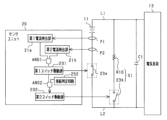
図2に基づいて、センサユニット20について詳しく説明する。センサユニット20は、検出対象の電池モジュール11の電流を検出する電流検出部21と、検出対象の電池モジュール11の電圧を検出する電圧検出部22と、を備える。また、検出対象の電池モジュール11と電気負荷13との間(若しくは直列接続される電池モジュール11の間)を接続する電気経路上には、検出対象の電池モジュール11と電気負荷13との間の通電及び通電遮断を切り替えるスイッチ部としてのスイッチ23aが設けられている。センサユニット20は、このスイッチ23aのオンオフ制御を実施するスイッチ駆動部23を備える。スイッチ23aは、例えば、リレースイッチである。スイッチ23aをパイロヒューズにより実現してもよい。
The
また、センサユニット20は、各種制御を実施する制御部24を備える。制御部24は、例えば、CPUやメモリなどを備えたマイコンから構成される。制御部24は、電流検出部21、電圧検出部22及びスイッチ駆動部23に接続されている。また、制御部24は、通信経路L38や、通信IF25,35、絶縁素子26,36を介して制御ユニット30のMCU31と接続されており、制御ユニット30からの指示を入力し、指示に基づいて各種処理を実施する。例えば、制御部24は、制御ユニット30から、検出対象である電池モジュール11の電池状態の検出が指示されると、電流検出部21及び電圧検出部22から電池状態(電流及び電圧)を入力し、入力した電池状態を制御ユニット30に出力する。
The
また、制御部24は、制御ユニット30から検出対象である電池モジュール11の通電遮断が指示されると、スイッチ駆動部23に対して、スイッチ23aによる通電遮断を指示する。スイッチ駆動部23は、制御部24から通電遮断を入力すると、スイッチ23aをオフし、電池モジュール11の通電を遮断する。
Further, when the
次に、制御ユニット30について説明する。制御ユニット30は、MCU(Micro Controller Unit)31を備える。MCU31は、CPUやメモリなどを備えたマイコンの一種である。MCU31は、車両からの要求(アクセル開度など)を入力し、車両からの要求及び電池状態に基づいて、組電池10から電気負荷13への電力供給を指示する。具体的には、MCU31は、システムメインリレーSMRのオン制御を実行する。また、電気負荷13に回転電機等が含まれている場合には、MCU31は、システムメインリレーSMRのオン制御を実行するとともに、組電池10への充電を制御する場合もある。
Next, the
また、MCU31は、組電池10等に何らかの異常が生じた場合には、組電池10から電気負荷13への通電を遮断する。具体的には、MCU31は、システムメインリレーSMRのオフ制御を実行するとともに、スイッチ23aのオフ制御を指示する。
Furthermore, if any abnormality occurs in the assembled
また、制御ユニット30には、補助電源32に接続されており、補助電源32から供給された電力が、制御ユニット30に設けられた電源生成部33に供給される。電源生成部33は、補助電源32の供給電力を制御ユニット30の駆動電力に変換し、駆動電力をMCU31等の制御ユニット30を構成する各素子に供給する。
The
上述したように、制御ユニット30のMCU31が、車両からの要求及び電池状態に基づいて、組電池10(電池モジュール11を含む)と電気負荷との間の通電及び通電遮断を切り替えるように構成されている。このため、MCU31は、何らかの不具合で、センサユニット20との通信が切断され、センサユニット20から電池状態を取得できなくなると、通電及び通電遮断を行うことができなくなってしまう。また、同様にMCU31に異常が生じた場合においても、通電及び通電遮断を行うことができなくなる。
As described above, the
通信経路L38又はMCU31に異常が生じた場合、安全性を考慮して、組電池10と電気負荷13との間で通電を遮断することが望ましい。しかしながら、電気自動車の場合、組電池10と電気負荷13との間で通電を遮断すると、電気負荷13に含まれる主機(車両駆動源)としての回転電機への電力供給も遮断することとなり、この場合、車両が即時停止することとなる。このため、車両が道路において他の車両の進路をふさぐように、停止してしまう可能性もあり、問題となる。
When an abnormality occurs in the communication path L38 or the
一方、通信経路L38又はMCU31に異常が生じた場合であっても、組電池10や電気負荷13、及びその間の電気経路L1,L2に異常がない場合もありうる。したがって、組電池10等に異常がないのであれば、しばらくの間、電気負荷13に電力を供給し、車両が邪魔にならない程度移動可能にすることが好ましい。そこで、本実施形態では、以下のようにセンサユニット20を構成し、制御ユニット30との通信が途絶えてもしばらくの間、組電池10からの電力供給を可能としている。以下、センサユニット20の構成、具体的には、制御部24により実施されるスイッチ制御処理について図3に基づいて説明する。スイッチ制御処理は、制御部24により所定周期ごとに実施される。
On the other hand, even if an abnormality occurs in the communication path L38 or the
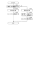
制御部24は、通信経路L38及びMCU31が正常であるか否かについて判定する(ステップS101)。具体的には、制御部24は、通信経路L38の断線(通信経路L38に設けられた素子の異常を含む)、及びMUC31の異常を検出する。通信経路L38の断線は、通信経路L38における電圧や、断線検出回路を用いるなど、種々の方法で検出可能である。同様に、MUC31の異常は、MUC31の応答がない場合など、種々の方法で検出可能である。これらの異常判定方法は、周知の方法であってよい。
The
ステップS101の判定結果が肯定の場合(通信経路L38及びMCU31が正常の場合)、制御部24は、制御ユニット30からスイッチ制御信号を入力し、入力したスイッチ制御信号に基づいて、スイッチ23aのオンオフを制御する(ステップS102)。
If the determination result in step S101 is affirmative (if the communication path L38 and
なお、制御ユニット30のMCU31は、車両要求及び電池状態等、スイッチ23aのオンオフに係るスイッチ制御情報を取得し、スイッチ制御情報に基づいて、スイッチ23aのオンオフを指示するスイッチ制御信号を出力する。
Note that the
一方、ステップS101の判定結果が否定の場合(通信経路L38又はMCU31が異常の場合)、制御部24は、電流検出部21及び電圧検出部22から電池状態(電流及び電圧)を取得する(ステップS103)。そして、制御部24は、取得した電池状態に基づいて、検出対象の電池モジュール11が正常であるか否かを判定する(ステップS104)。具体的には、制御部24は、入力した電流及び電圧がそれぞれ予め定められた正常値範囲内であるか否かを判定する。なお、本実施形態では、電流及び電圧に基づいて正常であるか否かを判定したが、いずれか一方に基づいて判定してもよい。また、電流及び電圧以外の値を入力し、それらと組み合わせて判定してもよいし、電流及び電圧以外の値に基づいて判定してもよい。
On the other hand, if the determination result in step S101 is negative (if the communication path L38 or
ステップS104の判定結果が肯定の場合(正常値範囲内である場合)、制御部24は、スイッチ駆動部23にスイッチ23aのオン状態(通電状態)を維持させるような通電維持制御を実施する(ステップS105)。そして、制御部24は、予め決められた時間経過後、再び、ステップS103の処理を実施する。
If the determination result in step S104 is affirmative (within the normal value range), the
一方、ステップS104の判定結果が否定の場合(正常値範囲内でない場合)、制御部24は、スイッチ駆動部23に対して、スイッチ23aがオフ状態(通電遮断状態)となるように、通電遮断制御を実施する(ステップS106)。具体的には、制御部24は、スイッチ駆動部23に対して、スイッチ23aによる通電遮断を指示する。スイッチ駆動部23は、制御部24から通電遮断を入力すると、スイッチ23aをオフし、電池モジュール11の通電を遮断する。
On the other hand, if the determination result in step S104 is negative (not within the normal value range), the
以上、本実施形態の構成により、次のような優れた効果を奏する。 As described above, the configuration of this embodiment provides the following excellent effects.
制御部24は、制御ユニット30又は通信経路L38に異常が生じた場合、電流検出部21及び電圧検出部22から電池状態を取得し、取得した電池状態に基づいて、電池モジュール11と電気負荷13との間の通電を維持するか否かを決定する。制御部24は、電池モジュール11と電気負荷13との間における通電遮断を決定した場合、当該決定に基づいてスイッチ駆動部23に対して、通電遮断の指示を行う。スイッチ駆動部23は、当該通電遮断の指示に基づいてスイッチ23aのオフ制御を実施する。このため、制御ユニット30又は通信経路L38に異常が生じた場合、電池モジュール11からの電力供給が途絶えて、車両が即時停止することを抑制できる。
When an abnormality occurs in the
制御部24は、制御ユニット30又は通信経路L38に異常が生じた場合、予め決められた時間経過するごとに電池状態を取得し、当該電池状態に基づいて通電を維持するか否かを決定する。このため、通電の維持を決定した後、電池モジュール11に異常が生じた場合、通電遮断を行い、電池モジュール11等を保護することが可能となる。
When an abnormality occurs in the
(第1実施形態の変形例)
・上記第1実施形態において、通電の維持を決定した後、予め決められた退避時間を経過した場合、制御部24は、通電遮断を実施してもよい。退避時間は、他の車両の通行の邪魔とならない道路脇へ自車両を移動させることが可能な時間(例えば、5分程度)であることが望ましい。これにより、より確実に電池モジュール11等を保護することが可能となる。
(Modified example of the first embodiment)
- In the first embodiment, if a predetermined evacuation time has elapsed after determining to maintain energization, the
・上記第1実施形態において、電池モジュール11から電力供給を受けて、センサユニット20の駆動電力を生成する電源生成部をセンサユニット20に設けてもよい。これにより、センサユニット20と制御ユニット30との間で電源線が遮断されても、センサユニット20は、駆動することが可能となる。
- In the first embodiment, the
(第2実施形態)
上記第1実施形態の構成を、次の第2実施形態のように変更してもよい。以下、第2実施形態では、主に、上記各実施形態で説明した構成に対する相違部分について説明する。また、第2実施形態では、基本構成として、第1実施形態の車両用電源システム100を例に説明する。
(Second embodiment)
The configuration of the first embodiment described above may be changed as in the following second embodiment. Hereinafter, in the second embodiment, differences from the configurations described in each of the above embodiments will be mainly explained. Further, in the second embodiment, the basic configuration will be explained using the vehicle
第2実施形態における制御ユニット30及びセンサユニット20の構成について図4を参照しつつ説明する。まず、制御ユニット30の構成について説明する。制御ユニット30のMCU31は、車両要求及び電池状態等、スイッチ23aのオンオフに係るスイッチ制御情報を取得する。そして、MCU31は、スイッチ制御情報に基づいて、スイッチ23aをオンまたはオフするかについて決定し、センサユニット20に対してスイッチ23aのオンオフを指示するスイッチ制御信号を出力する。例えば、MCU31は、組電池10等が正常である場合、スイッチ23aのオンを指示するスイッチ制御信号を出力する一方、組電池10等に異常が生じた場合、スイッチ23aのオフを指示するスイッチ制御信号を出力することとなる。
The configuration of the
また、MSC31は、制御ユニット30及び通信経路L38が正常である場合、一定期間T1経過するごとに、制御ユニット30及び通信経路L38が正常であることを通知する通知信号を出力する。一定期間T1は、任意の期間で構わないが、例えば、5秒間である。
Further, when the
次に、センサユニット20について説明する。図4に示すように、第2実施形態におけるセンサユニット20には、制御部24が省略されている。このため、第2実施形態における電流検出部21及び電圧検出部22は、制御ユニット30から、検出対象である電池モジュール11の電池状態の検出が指示されると、電流検出部21及び電圧検出部22に直接指示が入力されることとなる。そして電池状態の検出が指示されると、電流検出部21及び電圧検出部22は、電池状態(電流及び電圧)を検出し、入力した電池状態を制御ユニット30に出力するように構成されている。若しくは、電流検出部21及び電圧検出部22は、所定周期ごとに、電池状態(電流及び電圧)を検出し、入力した電池状態を制御ユニット30に出力するように構成されていてもよい。
Next, the
また、スイッチ駆動部23は、制御ユニット30からスイッチ制御信号が入力されると、スイッチ制御信号に基づいて、スイッチ23aのオンオフ状態を切り替えるように構成されている。つまり、スイッチ駆動部23は、スイッチ23aの駆動制御を実行する。
Further, the
また、スイッチ駆動部23は、駆動ラッチ機能を備えており、一定期間T1経過するまでに、制御ユニット30から通知信号が入力された場合には、スイッチ23aのオン状態を維持するように構成されている。一方、一定期間T1経過しても、制御ユニット30から通知信号の入力がなかった場合には、スイッチ23aのオフ状態に切り替えるように構成されている。以下、この機能を実現するためのスイッチ駆動処理について図5に基づいて説明する。スイッチ駆動処理は、スイッチ駆動部23により所定周期ごとに実施される。
Further, the
スイッチ駆動部23は、一定期間T1以内に制御ユニット30から通知信号を入力したか否かを判定する(ステップS201)。この判定結果が肯定の場合、スイッチ駆動部23は、通信経路又はMCU31等が正常であると判定する(ステップS202)。そして、制御部24は、スイッチ23aのオン状態を維持する(ステップS203)。
The
一方、ステップS201の判定結果が否定の場合、スイッチ駆動部23は、通信経路L38又はMCU31等に異常が生じたと判定する(ステップS204)。そして、スイッチ駆動部23は、予め決められた猶予時間Tonが経過するまで、スイッチ23aをオン状態に維持する(ステップS205)。猶予時間Tonは、他の車両の通行の邪魔とならない道路脇へ自車両を移動させることが可能な時間(例えば、5分程度)であって、なるべく短い時間であることが望ましい。猶予時間Tonの経過後、スイッチ駆動部23は、スイッチ23aをオフ状態に切り替え、電池モジュール11の通電を遮断する(ステップS206)。
On the other hand, if the determination result in step S201 is negative, the
第2実施形態における効果について説明する。 The effects of the second embodiment will be explained.
スイッチ駆動部23は、一定期間T1経過するまでに、制御ユニット30からの通知信号の入力があった場合には、通信経路L38などが正常であると判断し、スイッチ23aのオン状態を維持する。一方、一定期間T1経過しても、制御ユニット30からの通知信号の入力がなかった場合には、何らかの異常が生じたと判断し、スイッチ23aをオフ状態に切り替える。これにより、異常を判断する制御部24を備えなくても、簡単な機構で、しばらくの間、通電を維持し、その後、通電を遮断させることが可能となる。
If a notification signal is input from the
(第2実施形態の変形例)
・上記第2実施形態において、スイッチ駆動部23は、電流検出部21や電圧検出部22により検出された電池状態に基づいて、スイッチ23aのオン状態を維持するか否かを決定してもよい。
(Modified example of second embodiment)
- In the second embodiment, the
(第3実施形態)
上記第1実施形態の構成を、次の第3実施形態のように変更してもよい。以下、第3実施形態では、主に、上記各実施形態で説明した構成に対する相違部分について説明する。また、第3実施形態では、基本構成として、第1実施形態の車両用電源システム100を例に説明する。
(Third embodiment)
The configuration of the first embodiment described above may be changed as in the following third embodiment. Hereinafter, in the third embodiment, differences from the configurations described in each of the above embodiments will be mainly explained. Further, in the third embodiment, the basic configuration will be explained using the vehicle
第3実施形態におけるセンサユニット20について説明する。図6に示すように、第3実施形態におけるセンサユニット20には、制御部24が省略されている。このため、第3実施形態における電流検出部21及び電圧検出部22は、制御ユニット30から、検出対象である電池モジュール11の電池状態の検出が指示されると(若しくは所定周期ごとに)、電池状態(電流及び電圧)を検出し、入力した電池状態を制御ユニット30に出力するように構成されている。若しくは、電流検出部21及び電圧検出部22は、所定周期ごとに、電池状態(電流及び電圧)を検出し、入力した電池状態を制御ユニット30に出力するように構成されていてもよい。
The
また、第2実施形態と同様に、MCU31は、スイッチ制御信号を出力するように構成されており、スイッチ駆動部23は、制御ユニット30からスイッチ制御信号が入力されると、スイッチ制御信号に基づいて、スイッチ23aのオンオフ状態を切り替えるように構成されている。
Further, similarly to the second embodiment, the
また、このスイッチ駆動部23は、センサユニット20に設けられたセンサ側電源生成部29に接続され、センサ側電源生成部29から駆動電力が供給される。センサ側電源生成部29は、制御ユニット30の電源生成部33と接続されており、電源生成部33から電力が供給される。電源生成部33とセンサ側電源生成部29との間には、電源供給スイッチ37が設けられており、MCU31によりオンオフされるように構成されている。つまり、スイッチ駆動部23は、電源生成部33から供給される電力を駆動電力としてスイッチ23aのオン状態を維持するように構成されている。このため、電源供給スイッチ37がオフ状態に切り替えられ、制御ユニット30から駆動電力の供給が遮断されると、スイッチ23aのオン状態を維持することができず、オフ状態に切り替えられることとなる。
Further, this
第3実施形態における制御ユニット30の構成について説明する。制御ユニット30のMCU31は、所定周期ごとに図7に示すスイッチ駆動指示処理を実行する。MCU31は、通信経路L38及びセンサユニット20が正常であるか否かについて判定する(ステップS301)。具体的には、MCU31は、通信経路L38の断線(通信経路L38に設けられた素子の異常を含む)、及びセンサユニット20の異常を検出する。通信経路L38の断線の検出方法は、第1実施形態と同様である。センサユニット20の異常は、センサユニット20からの応答がない場合や、センサユニット20から異常信号を入力した場合など、種々の方法で検出可能である。これらの異常判定方法は、周知の方法であってもよい。
The configuration of the
この判定結果が肯定の場合、つまり、正常である場合、MCU31は、電池状態等に基づいて、スイッチ制御信号を出力する(ステップS302)。そして、スイッチ駆動指示処理を終了する。
If this determination result is affirmative, that is, if it is normal, the
一方、ステップS301の判定結果が否定の場合、つまり、通信経路L38又はセンサユニット20に異常が生じた場合、直前に取得した最新の電池状態に基づいて、スイッチ23aのオン状態を維持するか否かを判定する(ステップS303)。
On the other hand, if the determination result in step S301 is negative, that is, if an abnormality occurs in the communication path L38 or the
ステップS303の判定結果が肯定の場合、MCU31は、予め決められた猶予時間Tonだけセンサユニット20への電力供給を維持する(ステップS304)。これにより、スイッチ駆動部23に駆動電力が供給され続けるため、スイッチ23aのオン状態が維持される。なお、ステップS304において、MCU31は、上位ECUなどの外部装置に対して、異常が生じた旨の通知などを行ってもよい。猶予時間Tonは、第2実施形態と同様である。
If the determination result in step S303 is affirmative, the
そして、MCU31は、猶予時間Tonの経過後、センサユニット20への駆動電力の供給を停止する(ステップS305)。これにより、スイッチ駆動部23は、スイッチ23aのオン状態を維持することができなくなり、スイッチ23aは、オフ状態に切り替えられる。その結果、電池モジュール11と電気負荷13との間の通電が遮断される。
Then, the
また、ステップS303の判定結果が肯定の場合、MSC31は、ステップS305に移行して、センサユニット20への駆動電力の供給を停止する。これにより、前述同様に、電池モジュール11と電気負荷13との間の通電が遮断される。
Further, if the determination result in step S303 is affirmative, the
第3実施形態における効果について説明する。 The effects of the third embodiment will be explained.
MCU31は、通信経路L38又はセンサユニット20に異常が生じた場合、猶予時間Tonの経過後、センサユニット20への駆動電力の供給を停止して、スイッチ23aをオフ状態に切り替えさせる。これにより、センサユニット20に、異常を検出する制御部24を備えなくても、簡単な機構で、しばらくの間、通電を維持し、その後、通電を遮断させることが可能となる。
If an abnormality occurs in the communication path L38 or the
(第3実施形態の変形例)
・上記第3実施形態と、上記第1実施形態又は上記第2実施形態とを組み合わせてもよい。これにより、制御ユニット30及びセンサユニット20のうちどちらに異常が生じても、車両が即時停止することを抑制することができる。
(Modification of third embodiment)
- The third embodiment may be combined with the first embodiment or the second embodiment. Thereby, even if an abnormality occurs in either the
・上記第3実施形態において、通信経路L38等に異常が生じた場合、最新の電池状態に基づいてスイッチ23aのオン状態を維持するか否かを判定したが、判定せずに猶予時間Tonが経過するまで、オン状態を維持してもよい。
- In the third embodiment, when an abnormality occurs in the communication path L38 etc., it is determined whether or not to maintain the on state of the
(第4実施形態)
上記第1実施形態の構成を、次の第4実施形態のように変更してもよい。以下、第3実施形態では、主に、上記各実施形態で説明した構成に対する相違部分について説明する。また、第4実施形態では、基本構成として、第1実施形態の車両用電源システム100を例に説明する。
(Fourth embodiment)
The configuration of the first embodiment described above may be changed as in the following fourth embodiment. Hereinafter, in the third embodiment, differences from the configurations described in each of the above embodiments will be mainly explained. Further, in the fourth embodiment, the basic configuration will be explained using the vehicle
図8に示すように、第4実施形態のセンサユニット20は、複数(本実施形態では2つ)の電流検出部21を備える。なお、第1実施形態と異なり、電圧検出部22については、備えていても、備えていなくてもどちらでもよい。
As shown in FIG. 8, the
2つの電流検出部21は、それぞれ電流を検出する位置が異なっている。第4実施形態において、センサユニット20の検出対象となる電池モジュール11付近の電気経路上における第1位置P1の電流(第1電流値)を検出する第1電流検出部21aと、第1電流検出部21aに比較して電池モジュール11からの位置が遠く、スイッチ23a付近の電気経路上における第2位置P2の電流(第2電流値)を検出する第2電流検出部21bが存在する。
The two
第1電流検出部21aは、第1位置P1の電流を検出し、当該電流の値が、予め決められた第1閾値以上である場合には、その旨を示す第1検出信号を出力する。第2電流検出部21bは、第2位置P2の電流を検出し、当該電流の値が、予め決められた第2閾値以上である場合には、その旨を示す第2検出信号を出力する。第2実施形態において、第1閾値及び第2閾値は、同じ値Thとされている。
The first
第1電流検出部21a及び第2電流検出部21bは、アンド回路AND1に接続されており、アンド回路AND1に第1検出信号及び第2検出信号が入力されるように構成されている。アンド回路AND1は、図9に示すように、第1検出信号及び第2検出信号が入力されると、過電流検出信号を出力する。
The first
第4実施形態におけるスイッチ駆動部231は、アンド回路AND1に接続されており、過電流検出信号を入力可能に構成されている。アンド回路AND1から過電流検出信号を入力すると、スイッチ駆動部231は、スイッチ23aをオン状態からオフ状態に切り替えるように構成されている。
The
第4実施形態における効果について説明する。 The effects of the fourth embodiment will be explained.
異なる2か所の位置(第1位置P1及び第2位置P2)にて過電流が発生しているか否かを検出するため、ノイズに対して強くなり、誤検出を抑制することができる。 Since it is detected whether or not overcurrent is occurring at two different positions (first position P1 and second position P2), it is resistant to noise and can suppress false detection.
(第4実施形態の変形例)
・上記第4実施形態において、第1閾値と第2閾値は、同じ値であったが、図10に示すように、異なる値Th1,Th2であってもよい。これにより、ノイズが発生しても、誤動作を抑制することができる。
(Modified example of the fourth embodiment)
- In the fourth embodiment, the first threshold value and the second threshold value are the same value, but as shown in FIG. 10, they may be different values Th1 and Th2. Thereby, even if noise occurs, malfunctions can be suppressed.
・上記第4実施形態において、第1電流検出部21aと、第2電流検出部21bとで、サンプリングレート又は内部エラーカウント回数を異ならせてもよい。例えば、第1電流検出部21aは、第1閾値を超えた回数(第1回数)が第1の内部エラーカウント回数以上となった場合に、第1検出信号を出力するように構成するとともに、第2電流検出部21bは、第2閾値を超えた回数(第2回数)が第2の内部エラーカウント回数以上となった場合に、第2検出信号を出力するように構成してもよい。また、第1電流検出部21aは、第1閾値を超えている時間が、第1の時間以上となった場合に、第1検出信号を出力するように構成するとともに、第2電流検出部21bは、第2閾値を超えている時間が、第2の時間以上となった場合に、第2検出信号を出力するように構成してもよい。これにより、ノイズなどの影響により、極めて短い時間だけ過電流が発生した場合において、誤検出することを抑制できる。
- In the fourth embodiment, the first
・上記第4実施形態において、第1電流検出部21aは、ホールセンサ式であっても、シャント抵抗式であってもよい。同様に、第2電流検出部21bは、ホールセンサ式であっても、シャント抵抗式であってもよい。これにより、要求される仕様によって、適宜変更することが可能となる。
- In the fourth embodiment, the first
・上記第4実施形態及びその変形例において、上記第2実施形態又は上記第3実施形態と適宜組み合わせて実施してもよい。 - The fourth embodiment and its modifications may be implemented in combination with the second embodiment or the third embodiment as appropriate.
(第5実施形態)
上記第4実施形態の構成を、次の第5実施形態のように変更してもよい。以下、第5実施形態では、主に、上記各実施形態で説明した構成に対する相違部分について説明する。また、第5実施形態では、基本構成として、第4実施形態の車両用電源システム100を例に説明する。
(Fifth embodiment)
The configuration of the fourth embodiment described above may be changed as in the following fifth embodiment. Hereinafter, in the fifth embodiment, differences from the configurations described in each of the above embodiments will be mainly explained. Further, in the fifth embodiment, the basic configuration will be explained using the vehicle
図11に示すように、第5実施形態において、電池モジュール11及び電気負荷13との間に、コンデンサC1の電荷を素早く放電するための放電回路51が設けられている。放電回路51は、コンデンサC1、電池モジュール11及び電気負荷13と並列となるように接続されている。放電回路51は、抵抗体R10と、スイッチ23bの直列接続体から構成されている。スイッチ23bは、通常、オフ状態(通電遮断状態)となるように設定されている。
As shown in FIG. 11, in the fifth embodiment, a
第5実施形態のセンサユニット20は、第4実施形態と同様に、第1電流検出部21a、第2電流検出部21b、アンド回路AND1、及びスイッチ駆動部231を備えている。そして、第5実施形態のセンサユニット20は、上記構成に加えて、第2スイッチ駆動部232を備える。なお、第5実施形態では、スイッチ駆動部231を便宜上、第1スイッチ駆動部231と示す。
The
第2スイッチ駆動部232は、遅延回路D1を介して、アンド回路AND1の出力端子に接続されている。図11に示すように、第1検出信号及び第2検出信号がアンド回路AND1に入力されて、アンド回路AND1から過電流検出信号が出力されると、遅延回路D1により、第1スイッチ駆動部231よりも所定時間遅れて、過電流検出信号が第2スイッチ駆動部232に入力される。
The second
第2スイッチ駆動部232は、過電流検出信号を入力すると、スイッチ23bをオン状態に切り替える。これにより、第1スイッチ駆動部231によるスイッチ23aのオフ状態への切り替えに遅れて、所定時間経過後にスイッチ23bがオン状態となる。このため、放電回路51によって、コンデンサC1の電荷が放電される。
When the
上記第5実施形態の効果について説明する。 The effects of the fifth embodiment will be explained.
第2スイッチ駆動部232は、電池モジュール11の通電が遮断されて所定時間経過後、スイッチ23bをオン状態として、放電回路51によって、コンデンサC1の電荷を放電させる。これにより、素早くコンデンサC1の電荷を放電させることが可能となる。
After a predetermined period of time has elapsed since the
(第5実施形態の変形例)
・上記第5実施形態において、第2スイッチ駆動部232は、電池モジュール11の通電が遮断されて所定時間経過後、スイッチ23bをオン状態とするように構成されていた。この別例として、図12に示すように、スイッチ23aがオフ状態に切り替えられたことを判定する接続判定回路52を備えてもよい。そして、第2スイッチ駆動部232は、接続判定回路52からスイッチ23aがオフ状態に切り替えられたと判定された場合、スイッチ23bをオン状態に切り替えるように構成されていてもよい。
(Modification of fifth embodiment)
- In the fifth embodiment, the second
・上記第5実施形態及びその変形例において、上記第2実施形態又は上記第3実施形態と適宜組み合わせて実施してもよい。 - The fifth embodiment and its modifications may be implemented in combination with the second embodiment or the third embodiment as appropriate.
(第6実施形態)
上記第5実施形態の構成を、次の第6実施形態のように変更してもよい。以下、第5実施形態では、主に、上記各実施形態で説明した構成に対する相違部分について説明する。また、第6実施形態では、基本構成として、第5実施形態の車両用電源システム100を例に説明する。
(Sixth embodiment)
The configuration of the fifth embodiment may be modified as in the following sixth embodiment. Hereinafter, in the fifth embodiment, differences from the configurations described in each of the above embodiments will be mainly explained. Further, in the sixth embodiment, the basic configuration will be explained using the vehicle
図13に示すように、第6実施形態における組電池10は、第1電池モジュール61及び第2電池モジュール62により構成されている。そして、第1電池モジュール61及び第2電池モジュール62は、直列接続及び並列接続を変更可能に構成されている。
As shown in FIG. 13, the assembled
詳しく説明すると、第1電池モジュール61及び第2電池モジュール62は、スイッチF1を介して直列に接続されている。第1電池モジュール61に対して第1の接続切替スイッチS1が並列に接続されている。第1の接続切替スイッチS1は、一端が正極側電気経路L1に接続されており、他端がスイッチF1と第2電池モジュール62との間に接続されている。同様に、第2電池モジュール62に対して第2の接続切替スイッチS2が並列に接続されている。第2の接続切替スイッチS2は、一端が負極側電気経路L2に接続されており、他端がスイッチF1と第1電池モジュール61との間に接続されている。
To explain in detail, the
第1電池モジュール61及び第2電池モジュール62が直列に接続される場合、第1の接続切替スイッチS1及び第2の接続切替スイッチS2がオフ状態に切り替えられる。第1電池モジュール61及び第2電池モジュール62が並列に接続される場合、第1の接続切替スイッチS1及び第2の接続切替スイッチS2がオン状態に切り替えられる。
When the
第1の接続切替スイッチS1及び第2の接続切替スイッチS2は、制御ユニット30やセンサユニット20によりオンオフ制御されてもよいし、上位ECUなどによりオンオフ制御されてもよい。なお、組電池10から電気負荷13に電力が供給される場合、第1電池モジュール61と第2電池モジュール62とが直列接続される。一方、電気負荷13に含まれる回転電機から組電池10へ電力が供給される場合(つまり、充電される場合)、第1電池モジュール61と第2電池モジュール62とが並列接続される。
The first connection changeover switch S1 and the second connection changeover switch S2 may be controlled on and off by the
また、第6実施形態において、センサユニット20は、駆動電力が低圧である低圧基板63と、低圧基板63よりも駆動電力が高くなる高圧基板64が設けられている。低圧基板63には、第1電流検出部21aが設けられ、高圧基板64には、第2電流検出部21bが設けられている。
Further, in the sixth embodiment, the
第6実施形態において、第1電流検出部21aは、第1電池モジュール61と第2電池モジュール62との間の電気経路において、第2の接続切替スイッチS2の接続点よりも第1電池モジュール61の負極端子側における第1の地点P11に流れる電流を検出する。第1の地点P11は、いずれの接続態様であっても第1電池モジュール61からの電流を検出可能な地点である。
In the sixth embodiment, the first
また、第6実施形態において、第2電流検出部21bは、第1電池モジュール61と第2電池モジュール62との間の電気経路において、第1の接続切替スイッチS1の接続点よりも第2電池モジュール62の正極端子側における第2の地点P12に流れる電流を検出する。第2の地点P12は、いずれの接続態様であっても第2電池モジュール62からの電流を検出可能な地点である。
Further, in the sixth embodiment, the second
第6実施形態において、第1電流検出部21a及び第2電流検出部21bは、異常判定回路53に接続されている。異常判定回路53は、高圧基板64に設けられている。異常判定回路53は、第1電池モジュール61及び第2電池モジュール62が直列接続されているか否かに係る接続情報が入力されるように構成されている。
In the sixth embodiment, the first
異常判定回路53は、第1電池モジュール61及び第2電池モジュール62が直列接続されている場合、第1検出信号及び第2検出信号が入力されると、過電流検出信号を出力する。一方、異常判定回路53は、第1電池モジュール61及び第2電池モジュール62が並列接続されている場合(直列接続でない場合)、第1検出信号及び第2検出信号のうちいずれかが入力されると、過電流検出信号を出力する。
When the
第6実施形態のセンサユニット20は、第5実施形態と同様に、第1スイッチ駆動部231及び第2スイッチ駆動部232を備える。
The
第6実施形態における第1スイッチ駆動部231は、異常判定回路53に接続されており、過電流検出信号を入力可能に構成されている。異常判定回路53から過電流検出信号を入力すると、第1スイッチ駆動部231は、スイッチ23aをオン状態からオフ状態に切り替えるように構成されている。
The first
第2スイッチ駆動部232は、遅延回路D1を介して、異常判定回路53の出力端子に接続されている。第5実施形態と同様に、異常判定回路53から過電流検出信号が出力されると、遅延回路D1により、第1スイッチ駆動部231よりも所定時間遅れて、過電流検出信号が第2スイッチ駆動部232に入力される。
The second
第2スイッチ駆動部232は、過電流検出信号を入力すると、スイッチ23bをオン状態に切り替える。これにより、第1スイッチ駆動部231によるスイッチ23aのオフ状態への切り替えに遅れて、所定時間経過後にスイッチ23bがオン状態となる。このため、放電回路51によって、コンデンサC1の電荷が放電される。
When the
上記第6実施形態の効果は、上記第5実施形態の効果に加えて、以下の効果を有する。 In addition to the effects of the fifth embodiment, the sixth embodiment has the following effects.
組電池10から電気負荷13に電力が供給される場合、第1電池モジュール61と第2電池モジュール62とが直列接続される。一方、電気負荷13に含まれる回転電機から組電池10へ電力が供給される場合(つまり、充電される場合)、第1電池モジュール61と第2電池モジュール62とが並列接続される。このため、電気負荷13への供給電力を高圧にする一方で、充電電圧を低くすることができる。このため、回転電機から供給される充電電圧を昇圧するための構成を省略又は簡素化することができる。
When power is supplied from the assembled
異常判定回路53は、第1電池モジュール61及び第2電池モジュール62が直列接続されている場合、第1検出信号及び第2検出信号が入力されると、過電流検出信号を出力する。一方、異常判定回路53は、第1電池モジュール61及び第2電池モジュール62が並列接続されている場合、第1検出信号及び第2検出信号のうちいずれかが入力されると、過電流検出信号を出力する。これにより、接続態様に応じて、過電流を適切に検出することが可能となる。なお、充電される場合、回転電機以外の電気負荷13と組電池10とは通電が遮断されるため、組電池10へのノイズが少なくなることが予想される。このため、第1電池モジュール61と第2電池モジュール62とが並列接続されるときに、過電流を検出することにより、適切に過電流を検出することが可能となる。
When the
(第6実施形態の変形例)
・上記実施形態において、いずれの接続状態であっても、第1検出信号及び第2検出信号が出力されたとき、過電流検出信号が出力されるように構成されてもよい。
(Modified example of the sixth embodiment)
- In the above embodiment, the overcurrent detection signal may be output when the first detection signal and the second detection signal are output, regardless of the connection state.
・上記第6実施形態及びその変形例において、上記第2実施形態又は上記第3実施形態と適宜組み合わせて実施してもよい。 - The sixth embodiment and its modifications may be implemented in combination with the second embodiment or the third embodiment as appropriate.
・上記第6実施形態において、センサユニット20を、低圧基板63と高圧基板64に分けて設けたが、分けなくてもよい。
- In the sixth embodiment, the
・上記第6実施形態において、異常が生じた場合、第1電池モジュール61と第2電池モジュール62とが並列接続されるように構成されてもよい。そして、過電流が発生していないと判定された場合、直列接続されるように構成されてもよい。
- In the sixth embodiment, if an abnormality occurs, the
・上記第6実施形態において、第1の地点P11は、いずれの接続態様であっても第1電池モジュール61からの電流を検出可能な地点であれば、任意のその地点を変更してもよい。同様に、第2の地点P12は、いずれの接続態様であっても第2電池モジュール62からの電流を検出可能な地点であれば、任意のその地点を変更してもよい。
- In the sixth embodiment, the first point P11 may be changed to any point as long as the current from the
11…電池モジュール、13…電気負荷、20…センサユニット、21…電流検出部、23a…スイッチ、23…スイッチ駆動部、24…制御部、30…制御ユニット、100…車両用電源システム、L38…通信経路。
DESCRIPTION OF
Claims (5)
前記センサユニットは、
前記蓄電池の電池状態を検出する検出部(21)と、
前記蓄電池と前記電気負荷との間に設けられたスイッチ部(23a)を駆動制御するスイッチ駆動部(23)と、
前記スイッチ駆動部を制御する制御部(24)と、を備え、
前記制御部は、
前記制御ユニットからの指示に基づいて、前記スイッチ駆動部を制御して、前記蓄電池と前記電気負荷との間の通電及び通電遮断を切り替えるとともに、
前記制御ユニット又は前記通信経路における異常を判定した場合、前記検出部が検出した電池状態に基づいて、前記蓄電池と前記電気負荷との間の通電を維持するか否かを決定し、当該決定に基づいて前記スイッチ駆動部を制御して、前記蓄電池と前記電気負荷との間の通電及び通電遮断を切り替え、
前記検出部は、前記蓄電池と前記電気負荷との間の電気経路上における第1の地点(P1)における第1電流値を検出する第1電流検出部(21a)と、前記電気経路上において第1の地点とは異なる第2の地点(P2)における第2電流値を検出する第2電流検出部(21b)と、を備え、
前記スイッチ駆動部は、前記第1電流値が第1閾値以上であって、前記第2電流値が第2閾値以上である場合、前記蓄電池と前記電気負荷との間の通電を遮断させるように前記スイッチ部を駆動制御するものであり、
前記スイッチ駆動部は、前記第1電流値が第1閾値以上となった回数が、予め決められた第1回数以上となった場合であって、前記第2電流値が第2閾値以上となった回数が、第1回数とは異なる第2回数以上となった場合、前記蓄電池と電気負荷との間の通電を遮断させるように前記スイッチ部を駆動制御する車両用電源システム。 A sensor unit (20) detects the battery state of a storage battery (11) capable of supplying power to an electric load (13), and inputs the battery state from the sensor unit via a communication path (L38). A vehicle power supply system (100) comprising: a control unit (30) that instructs energization and interruption of energization between the storage battery and the electric load based on a battery state that has been determined;
The sensor unit is
a detection unit (21) that detects a battery state of the storage battery;
a switch drive unit (23) that drives and controls a switch unit (23a) provided between the storage battery and the electric load;
A control unit (24) that controls the switch drive unit,
The control unit includes:
Controlling the switch drive unit based on instructions from the control unit to switch between energization and de-energization between the storage battery and the electric load;
When it is determined that there is an abnormality in the control unit or the communication path, it is determined whether or not to maintain energization between the storage battery and the electric load based on the battery state detected by the detection unit, and based on the determination, controlling the switch drive unit based on the switching between energization and energization interruption between the storage battery and the electric load ;
The detection unit includes a first current detection unit (21a) that detects a first current value at a first point (P1) on the electrical path between the storage battery and the electrical load; a second current detection unit (21b) that detects a second current value at a second point (P2) different from the first point;
The switch driver is configured to cut off current flow between the storage battery and the electric load when the first current value is a first threshold value or more and the second current value is a second threshold value or more. It drives and controls the switch section,
The switch driver is configured to control the switch drive unit when the number of times the first current value is equal to or greater than a first threshold is equal to or greater than a predetermined first number of times, and the second current value is equal to or greater than a second threshold. A power supply system for a vehicle that drives and controls the switch unit so as to cut off electricity between the storage battery and the electric load when the number of times the battery has been used is a second number or more different from the first number of times .
前記センサユニットは、
前記蓄電池の電池状態を検出する検出部(21)と、
前記制御ユニットの指示に基づいて、前記蓄電池と前記電気負荷との間の通電及び通電遮断を切り替えるように、前記蓄電池と前記電気負荷との間に設けられたスイッチ部(23a)を駆動制御するスイッチ駆動部(23)と、を備え、
前記制御ユニットは、正常時において、一定期間ごとに、正常であることを示す通知信号を出力するように構成されており、
前記スイッチ駆動部は、一定期間ごとに前記制御ユニットから前記通知信号を入力した場合には、前記蓄電池と前記電気負荷との間の通電を維持する一方、一定期間ごとに前記制御ユニットから前記通知信号を入力しなかった場合には、予め決められた猶予時間の経過後、前記蓄電池と前記電気負荷との間の通電を遮断するように、前記スイッチ部を駆動制御し、
前記検出部は、前記蓄電池と前記電気負荷との間の電気経路上における第1の地点(P1)における第1電流値を検出する第1電流検出部(21a)と、前記電気経路上において第1の地点とは異なる第2の地点(P2)における第2電流値を検出する第2電流検出部(21b)と、を備え、
前記スイッチ駆動部は、前記第1電流値が第1閾値以上であって、前記第2電流値が第2閾値以上である場合、前記蓄電池と前記電気負荷との間の通電を遮断させるように前記スイッチ部を駆動制御するものであり、
前記スイッチ駆動部は、前記第1電流値が第1閾値以上となった回数が、予め決められた第1回数以上となった場合であって、前記第2電流値が第2閾値以上となった回数が、第1回数とは異なる第2回数以上となった場合、前記蓄電池と電気負荷との間の通電を遮断させるように前記スイッチ部を駆動制御する車両用電源システム。 A sensor unit (20) detects the battery state of a storage battery (11) capable of supplying power to an electric load (13), and inputs the battery state from the sensor unit via a communication path (L38). A vehicle power supply system (100) comprising: a control unit (30) that instructs energization and interruption of energization between the storage battery and the electric load based on a battery state that has been determined;
The sensor unit is
a detection unit (21) that detects a battery state of the storage battery;
Based on instructions from the control unit, a switch unit (23a) provided between the storage battery and the electric load is drive-controlled to switch between energization and de-energization between the storage battery and the electric load. A switch drive unit (23);
The control unit is configured to output a notification signal indicating normality at regular intervals during normal times,
When the notification signal is input from the control unit at regular intervals, the switch driving section maintains energization between the storage battery and the electric load, and receives the notification from the control unit at regular intervals. If the signal is not input, the switch section is driven and controlled so as to cut off the electricity between the storage battery and the electric load after a predetermined grace period has elapsed ;
The detection unit includes a first current detection unit (21a) that detects a first current value at a first point (P1) on the electrical path between the storage battery and the electrical load; a second current detection unit (21b) that detects a second current value at a second point (P2) different from the first point;
The switch driver is configured to cut off current flow between the storage battery and the electric load when the first current value is a first threshold value or more and the second current value is a second threshold value or more. It drives and controls the switch section,
The switch driver is configured to control the switch drive unit when the number of times the first current value is equal to or greater than a first threshold is equal to or greater than a predetermined first number of times, and the second current value is equal to or greater than a second threshold. A power supply system for a vehicle that drives and controls the switch unit so as to cut off electricity between the storage battery and the electric load when the number of times the battery has been used is a second number or more different from the first number of times .
前記第1電池モジュール及び前記第2電池モジュールは、直列接続及び並列接続を変更可能に構成されており、
前記第1の地点は、いずれの接続態様であっても前記第1電池モジュールからの電流を検出可能な地点(P11)であり、
前記第2の地点は、いずれの接続態様であっても前記第2電池モジュールからの電流を検出可能な地点(P12)であり、
前記スイッチ駆動部は、
前記第1電池モジュール及び前記第2電池モジュールが直列接続されている場合、前記第1電流値が第1閾値以上であって、前記第2電流値が第2閾値以上であるとき、前記蓄電池と電気負荷との間の通電を遮断させるように前記スイッチ部を駆動制御し、
前記第1電池モジュール及び前記第2電池モジュールが並列接続されている場合、前記第1電流値が第1閾値以上であるとき、又は前記第2電流値が第2閾値以上であるとき、前記蓄電池と電気負荷との間の通電を遮断させるように前記スイッチ部を駆動制御する請求項1又は2に記載の車両用電源システム。 The storage battery is an assembled battery (10) composed of a first battery module (61) and a second battery module (62),
The first battery module and the second battery module are configured so that series connection and parallel connection can be changed,
The first point is a point (P11) where the current from the first battery module can be detected in any connection mode,
The second point is a point (P12) where the current from the second battery module can be detected in any connection mode,
The switch driving section includes:
When the first battery module and the second battery module are connected in series, when the first current value is a first threshold value or more and the second current value is a second threshold value or more, the storage battery Driving and controlling the switch unit to cut off current flow between the electric load and the electric load;
When the first battery module and the second battery module are connected in parallel, when the first current value is equal to or higher than the first threshold value, or when the second current value is equal to or higher than the second threshold value, the storage battery The vehicle power supply system according to claim 1 or 2, wherein the switch section is drive-controlled to cut off current flow between the electric load and the electric load.
前記電源生成部は、前記スイッチ駆動部にその駆動電力を供給するように構成されており、
前記制御ユニットは、前記センサユニットからの通信が遮断された場合又は前記センサユニットから異常が生じた旨の通信があった場合、直前に入力した電池状態に基づいて前記蓄電池と前記電気負荷との間の通電を所定期間維持するか否かを決定し、当該決定に基づいて前記駆動電力の供給を維持又は停止する請求項1~3のうちいずれか1項に記載の車両用電源システム。 The control unit includes a power generation section (33) that converts power supplied from an auxiliary power source to generate driving power,
The power generation unit is configured to supply drive power to the switch drive unit,
When communication from the sensor unit is cut off or when there is communication from the sensor unit indicating that an abnormality has occurred, the control unit controls the connection between the storage battery and the electrical load based on the battery state input immediately before. 4. The vehicle power supply system according to claim 1, wherein the vehicle power supply system determines whether or not to maintain energization for a predetermined period of time, and maintains or stops supply of the drive power based on the determination.
Priority Applications (5)
| Application Number | Priority Date | Filing Date | Title |
|---|---|---|---|
| JP2021136438A JP7416027B2 (en) | 2021-08-24 | 2021-08-24 | Vehicle power system |
| CN202280057832.XA CN117858822A (en) | 2021-08-24 | 2022-08-12 | Power supply system for vehicle |
| PCT/JP2022/030778 WO2023026874A1 (en) | 2021-08-24 | 2022-08-12 | Power supply system for vehicle |
| EP22861163.8A EP4393777A1 (en) | 2021-08-24 | 2022-08-12 | Power supply system for vehicle |
| US18/586,737 US20240190252A1 (en) | 2021-08-24 | 2024-02-26 | Vehicular power supply system |
Applications Claiming Priority (1)
| Application Number | Priority Date | Filing Date | Title |
|---|---|---|---|
| JP2021136438A JP7416027B2 (en) | 2021-08-24 | 2021-08-24 | Vehicle power system |
Publications (3)
| Publication Number | Publication Date |
|---|---|
| JP2023030995A JP2023030995A (en) | 2023-03-08 |
| JP2023030995A5 JP2023030995A5 (en) | 2023-07-31 |
| JP7416027B2 true JP7416027B2 (en) | 2024-01-17 |
Family
ID=85323217
Family Applications (1)
| Application Number | Title | Priority Date | Filing Date |
|---|---|---|---|
| JP2021136438A Active JP7416027B2 (en) | 2021-08-24 | 2021-08-24 | Vehicle power system |
Country Status (5)
| Country | Link |
|---|---|
| US (1) | US20240190252A1 (en) |
| EP (1) | EP4393777A1 (en) |
| JP (1) | JP7416027B2 (en) |
| CN (1) | CN117858822A (en) |
| WO (1) | WO2023026874A1 (en) |
Citations (7)
| Publication number | Priority date | Publication date | Assignee | Title |
|---|---|---|---|---|
| JP2008195255A (en) | 2007-02-14 | 2008-08-28 | Toyota Motor Corp | Vehicular power supply system |
| JP2008312396A (en) | 2007-06-15 | 2008-12-25 | Yazaki Corp | Power supply system for vehicle |
| JP2012093343A (en) | 2010-09-30 | 2012-05-17 | Gs Yuasa Corp | Failure detection device and failure detection method |
| JP2017051036A (en) | 2015-09-04 | 2017-03-09 | オートモーティブエナジーサプライ株式会社 | Vehicular power supply device and vehicle control device |
| JP2019110713A (en) | 2017-12-20 | 2019-07-04 | 株式会社Subaru | Power source system for electric vehicle |
| JP2019176559A (en) | 2018-03-27 | 2019-10-10 | 株式会社Subaru | Vehicle power unit |
| JP2020150568A (en) | 2019-03-11 | 2020-09-17 | 株式会社デンソー | Electric motor control device and electric motor control method |
Family Cites Families (1)
| Publication number | Priority date | Publication date | Assignee | Title |
|---|---|---|---|---|
| JP7543119B2 (en) | 2020-02-25 | 2024-09-02 | 芝浦メカトロニクス株式会社 | Substrate Processing Equipment |
-
2021
- 2021-08-24 JP JP2021136438A patent/JP7416027B2/en active Active
-
2022
- 2022-08-12 CN CN202280057832.XA patent/CN117858822A/en active Pending
- 2022-08-12 EP EP22861163.8A patent/EP4393777A1/en active Pending
- 2022-08-12 WO PCT/JP2022/030778 patent/WO2023026874A1/en active Application Filing
-
2024
- 2024-02-26 US US18/586,737 patent/US20240190252A1/en active Pending
Patent Citations (7)
| Publication number | Priority date | Publication date | Assignee | Title |
|---|---|---|---|---|
| JP2008195255A (en) | 2007-02-14 | 2008-08-28 | Toyota Motor Corp | Vehicular power supply system |
| JP2008312396A (en) | 2007-06-15 | 2008-12-25 | Yazaki Corp | Power supply system for vehicle |
| JP2012093343A (en) | 2010-09-30 | 2012-05-17 | Gs Yuasa Corp | Failure detection device and failure detection method |
| JP2017051036A (en) | 2015-09-04 | 2017-03-09 | オートモーティブエナジーサプライ株式会社 | Vehicular power supply device and vehicle control device |
| JP2019110713A (en) | 2017-12-20 | 2019-07-04 | 株式会社Subaru | Power source system for electric vehicle |
| JP2019176559A (en) | 2018-03-27 | 2019-10-10 | 株式会社Subaru | Vehicle power unit |
| JP2020150568A (en) | 2019-03-11 | 2020-09-17 | 株式会社デンソー | Electric motor control device and electric motor control method |
Also Published As
| Publication number | Publication date |
|---|---|
| CN117858822A (en) | 2024-04-09 |
| WO2023026874A1 (en) | 2023-03-02 |
| EP4393777A1 (en) | 2024-07-03 |
| US20240190252A1 (en) | 2024-06-13 |
| JP2023030995A (en) | 2023-03-08 |
Similar Documents
| Publication | Publication Date | Title |
|---|---|---|
| JP6614443B2 (en) | Battery device, vehicle, battery management program, and battery device management method | |
| JP7119401B2 (en) | FAILURE DIAGNOSIS DEVICE, POWER STORAGE DEVICE, FAILURE DIAGNOSIS METHOD | |
| US10913408B2 (en) | System for determining state of power relay assembly | |
| CN111699605B (en) | Battery control device | |
| JP2015008600A (en) | Switch failure diagnostic system and switch failure diagnostic method | |
| JP4171449B2 (en) | Power supply for vehicle | |
| JP6627732B2 (en) | Power supply circuit device | |
| JP2013092397A (en) | Battery monitoring device | |
| WO2015011531A1 (en) | Electrical storage system, battery system, and failure determination method | |
| JP6972027B2 (en) | Management device and power storage system | |
| US10115549B2 (en) | Electrical storage system | |
| KR101487577B1 (en) | Method and apparatus for detecting default of battery pack, and power relay assembly thereof | |
| US20200195016A1 (en) | Precharge controller | |
| JP2017079496A (en) | Contactor failure determining device and contactor failure determining method | |
| JP2018198519A (en) | Vehicle power supply device | |
| JP5167915B2 (en) | Auxiliary power supply system for electric power steering system | |
| JP6248672B2 (en) | Relay control device | |
| JP2017093008A (en) | Contactor failure determination device and contactor failure determination method | |
| JP7416027B2 (en) | Vehicle power system | |
| US20240183911A1 (en) | Anomaly detection apparatus and anomaly detection method | |
| JP6648217B2 (en) | Switch unit and battery device | |
| WO2021039177A1 (en) | Energization control device and power supply unit | |
| JP2020022366A (en) | vehicle | |
| WO2024185230A1 (en) | Power distribution device and wire-disconnect determination method | |
| JP7525461B2 (en) | Control device and battery pack |
Legal Events
| Date | Code | Title | Description |
|---|---|---|---|
| A521 | Request for written amendment filed |
Free format text: JAPANESE INTERMEDIATE CODE: A523 Effective date: 20230721 |
|
| A621 | Written request for application examination |
Free format text: JAPANESE INTERMEDIATE CODE: A621 Effective date: 20230721 |
|
| TRDD | Decision of grant or rejection written | ||
| A01 | Written decision to grant a patent or to grant a registration (utility model) |
Free format text: JAPANESE INTERMEDIATE CODE: A01 Effective date: 20231205 |
|
| A61 | First payment of annual fees (during grant procedure) |
Free format text: JAPANESE INTERMEDIATE CODE: A61 Effective date: 20231218 |
|
| R151 | Written notification of patent or utility model registration |
Ref document number: 7416027 Country of ref document: JP Free format text: JAPANESE INTERMEDIATE CODE: R151 |