WO2022202289A1 - 超音波診断装置および超音波診断装置の制御方法 - Google Patents
超音波診断装置および超音波診断装置の制御方法 Download PDFInfo
- Publication number
- WO2022202289A1 WO2022202289A1 PCT/JP2022/009978 JP2022009978W WO2022202289A1 WO 2022202289 A1 WO2022202289 A1 WO 2022202289A1 JP 2022009978 W JP2022009978 W JP 2022009978W WO 2022202289 A1 WO2022202289 A1 WO 2022202289A1
- Authority
- WO
- WIPO (PCT)
- Prior art keywords
- image
- ultrasonic
- optical
- ultrasonic probe
- probe
- Prior art date
- Legal status (The legal status is an assumption and is not a legal conclusion. Google has not performed a legal analysis and makes no representation as to the accuracy of the status listed.)
- Ceased
Links
Images







Classifications
-
- A—HUMAN NECESSITIES
- A61—MEDICAL OR VETERINARY SCIENCE; HYGIENE
- A61B—DIAGNOSIS; SURGERY; IDENTIFICATION
- A61B8/00—Diagnosis using ultrasonic, sonic or infrasonic waves
- A61B8/13—Tomography
- A61B8/14—Echo-tomography
-
- A—HUMAN NECESSITIES
- A61—MEDICAL OR VETERINARY SCIENCE; HYGIENE
- A61B—DIAGNOSIS; SURGERY; IDENTIFICATION
- A61B8/00—Diagnosis using ultrasonic, sonic or infrasonic waves
- A61B8/54—Control of the diagnostic device
-
- A—HUMAN NECESSITIES
- A61—MEDICAL OR VETERINARY SCIENCE; HYGIENE
- A61B—DIAGNOSIS; SURGERY; IDENTIFICATION
- A61B8/00—Diagnosis using ultrasonic, sonic or infrasonic waves
- A61B8/42—Details of probe positioning or probe attachment to the patient
- A61B8/4245—Details of probe positioning or probe attachment to the patient involving determining the position of the probe, e.g. with respect to an external reference frame or to the patient
-
- A—HUMAN NECESSITIES
- A61—MEDICAL OR VETERINARY SCIENCE; HYGIENE
- A61B—DIAGNOSIS; SURGERY; IDENTIFICATION
- A61B8/00—Diagnosis using ultrasonic, sonic or infrasonic waves
- A61B8/46—Ultrasonic, sonic or infrasonic diagnostic devices with special arrangements for interfacing with the operator or the patient
- A61B8/461—Displaying means of special interest
-
- A—HUMAN NECESSITIES
- A61—MEDICAL OR VETERINARY SCIENCE; HYGIENE
- A61B—DIAGNOSIS; SURGERY; IDENTIFICATION
- A61B8/00—Diagnosis using ultrasonic, sonic or infrasonic waves
- A61B8/46—Ultrasonic, sonic or infrasonic diagnostic devices with special arrangements for interfacing with the operator or the patient
- A61B8/461—Displaying means of special interest
- A61B8/463—Displaying means of special interest characterised by displaying multiple images or images and diagnostic data on one display
-
- A—HUMAN NECESSITIES
- A61—MEDICAL OR VETERINARY SCIENCE; HYGIENE
- A61B—DIAGNOSIS; SURGERY; IDENTIFICATION
- A61B8/00—Diagnosis using ultrasonic, sonic or infrasonic waves
- A61B8/46—Ultrasonic, sonic or infrasonic diagnostic devices with special arrangements for interfacing with the operator or the patient
- A61B8/467—Ultrasonic, sonic or infrasonic diagnostic devices with special arrangements for interfacing with the operator or the patient characterised by special input means
Definitions
- the present invention relates to an ultrasonic diagnostic apparatus that generates an ultrasonic image including an examination location of a subject and a control method for the ultrasonic diagnostic apparatus.
- an ultrasound diagnostic device in an ICU Intensive Care Unit
- a first person uses an ultrasound probe to inspect the subject.
- a part is inspected, an ultrasonic image of the inspection part is displayed on a monitor arranged outside the ICU, and a second person sees the ultrasonic image of the inspection part displayed on the monitor and performs remote diagnosis.
- Patent Documents 1 and 2 an ultrasonic image and an optical image including an ultrasonic probe captured using an optical camera included in a handheld ultrasonic diagnostic device body are displayed on a monitor of the device body. It is described to display.
- an optical camera is attached to a stationary ultrasonic diagnostic apparatus, an optical image of a diagnostic site is zoomed using this optical camera, and this optical image is recorded together with the ultrasonic image. is described.
- the handheld ultrasonic diagnostic apparatus disclosed in Patent Documents 1 and 2 when inspecting an inspection site of a subject, the user, for example, While scanning the area to be inspected by holding the ultrasonic probe in one hand, the apparatus body is held in the other hand and the subject including the ultrasonic probe being inspected is imaged using the optical camera of the apparatus body. do.
- an object of the present invention is to provide an ultrasonic diagnostic apparatus and a control method for the ultrasonic diagnostic apparatus that can enlarge and display on a monitor an optical image representing the position and orientation of an ultrasonic probe during examination of an examination site. to do.
- the present invention comprises an ultrasonic probe and a device main body connected to the ultrasonic probe,
- the main body of the device is an ultrasonic image generation unit that generates an ultrasonic image from a received signal obtained by transmitting and receiving an ultrasonic beam to and from an examination location of a subject using an ultrasonic probe; at least one optical camera for generating an optical image by imaging a subject including an ultrasound probe under inspection of an inspection site; a probe recognition unit that recognizes an ultrasonic probe from an optical image; a trimming unit that generates a trimmed image by trimming a region including the ultrasound probe from the optical image when the ultrasound probe is recognized; a monitor; and a display controller for displaying an ultrasonic image and a trimmed image on a monitor.
- At least one optical camera includes a plurality of optical cameras with different angles of view
- the device main body has an optical camera selection unit that selects one or more optical cameras from a plurality of optical cameras based on an instruction from a user;
- the plurality of optical cameras are preferably arranged on the same side surface of the device body.
- the optical camera selection unit selects one optical camera from among the plurality of optical cameras based on an instruction from the user
- the probe recognition unit recognizes the ultrasonic probe from an optical image generated by one optical camera
- the trimming unit generates a trimmed image from the optical image generated by one optical camera.
- the optical camera selection unit selects the first optical camera and the second optical camera from among the plurality of optical cameras based on an instruction by the user
- the first optical camera is a standard camera that generates a standard optical image by imaging the subject with a first angle of view
- the second optical camera is a wide-angle camera that generates a wide-angle optical image by imaging the subject at a second angle of view that is wider than that of the standard camera
- the probe recognition unit recognizes the ultrasonic probe from the standard optical image and the wide-angle optical image.
- the trimming unit generates a trimmed image from the standard optical image when the ultrasonic probe is recognized from both the standard optical image and the wide-angle optical image, the ultrasonic probe is recognized from the wide-angle optical image, and the standard It is preferable to generate a cropped image from the wide-angle optical image if the ultrasound probe is not visible from the optical image.
- the probe recognition unit recognizes the ultrasonic probe from the wide-angle optical image, and recognizes the ultrasonic probe from the standard optical image when the ultrasonic probe is recognized from the wide-angle optical image.
- the device main body has an area setting memory for storing one area preset from among the plurality of areas in the optical image divided into the plurality of preset areas,
- the probe recognition unit recognizes the ultrasonic probe from only one region, It is preferable that the trimming section generates a trimmed image from only one region.
- the probe recognition unit recognizes the ultrasonic probe only from the trimming area set based on the user's instruction in the optical image, It is preferable that the trimming unit generates a trimmed image only from the trimming area.
- the probe recognition unit preferably recognizes the ultrasonic probe held by the user from the optical image.
- the device main body has a notification unit that notifies that the ultrasonic probe is not recognized when the ultrasonic probe is not recognized.
- the display control unit displays the optical image on the monitor when the ultrasonic probe is not recognized, and displays the trimmed image on the monitor when the ultrasonic probe is recognized.
- the present invention comprises an ultrasonic probe and a device main body connected to the ultrasonic probe,
- the main body of the device is an ultrasonic image generation unit that generates an ultrasonic image from a received signal obtained by transmitting and receiving an ultrasonic beam to and from an examination location of a subject using an ultrasonic probe; at least one optical camera for generating an optical image by imaging a subject including an ultrasound probe under inspection of an inspection site; an area setting memory for storing one preset area from among the plurality of areas in the optical image divided into a plurality of preset areas; a trimming unit that generates a trimmed image by trimming one region from the optical image; a monitor; and a display controller for displaying an ultrasonic image and a trimmed image on a monitor.
- At least one optical camera includes a plurality of optical cameras with different angles of view
- the device main body has an optical camera selection unit that selects one or more optical cameras from a plurality of optical cameras based on an instruction from a user;
- the multiple optical cameras are arranged on the same side surface of the device body,
- the optical camera selection unit selects one optical camera from among the plurality of optical cameras based on an instruction from the user,
- the trimming unit generates a trimmed image from the optical image generated by one optical camera.
- the at least one optical camera includes a third optical camera located on the same side of the device body as the monitor,
- the main body of the device is a line-of-sight recognition unit that recognizes the user's line of sight based on the optical image generated by the third optical camera; and a device controller that freezes at least one of the ultrasound image and the optical image when a preset eye movement is recognized.
- the trimming unit generates a trimmed image by trimming a region including the subject within a range representing the position and orientation of the ultrasonic probe during inspection, in addition to the ultrasonic probe, from the optical image. is preferred.
- the present invention provides a step of generating an ultrasonic image from a received signal obtained by transmitting and receiving an ultrasonic beam to and from an examination location of a subject using an ultrasonic probe, wherein the ultrasonic image generating unit generates an ultrasonic image; generating an optical image by at least one optical camera imaging a subject including an ultrasound probe under inspection of the inspection site; a step in which the probe recognition unit recognizes the ultrasonic probe from the optical image; generating a trimmed image by trimming a region including the ultrasonic probe from the optical image when the ultrasonic probe is recognized; A display control unit displaying an ultrasonic image and a trimmed image on a monitor.
- the present invention provides a step of generating an ultrasonic image from a received signal obtained by transmitting and receiving an ultrasonic beam to and from an examination location of a subject using an ultrasonic probe, wherein the ultrasonic image generating unit generates an ultrasonic image; generating an optical image by at least one optical camera imaging a subject including an ultrasound probe under inspection of the inspection site; an area setting memory storing one preset area out of the multiple areas in the optical image divided into the preset multiple areas; a trimming unit generating a trimmed image by trimming one region from the optical image; A display control unit displaying an ultrasonic image and a trimmed image on a monitor.
- an ultrasonic image and a trimmed image generated by trimming an area including the ultrasonic probe under inspection from the optical image are displayed on the monitor. Therefore, according to the present invention, the user can determine the position and orientation of the ultrasonic probe at the time of generating the ultrasonic image during inspection of the inspection site of the subject by viewing the trimmed image in which the ultrasonic probe is magnified. can be easily grasped.
- FIG. 1 is a block diagram of a first embodiment showing the configuration of an ultrasonic diagnostic apparatus of the present invention
- FIG. 1 is a block diagram of an embodiment showing the configuration of a transmission/reception circuit
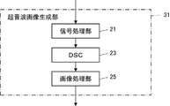
- FIG. 1 is a block diagram of an embodiment showing the configuration of an ultrasound image generator
- FIG. 3 is a block diagram of one embodiment showing the configuration of a trimming processing unit of the ultrasonic diagnostic apparatus of the first embodiment
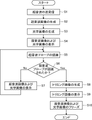
- FIG. 4 is a flowchart of one embodiment showing the operation of the ultrasonic diagnostic apparatus of the first embodiment
- FIG. 4 is a conceptual diagram of an embodiment showing a user examining the abdomen of a subject
- 1 is a conceptual diagram of one embodiment of a display screen of a monitor on which an ultrasound image and an optical image are displayed
- FIG. 1 is a conceptual diagram of one embodiment of a display screen of a monitor on which an ultrasound image and a cropped image are displayed;
- FIG. FIG. 2 is a block diagram of a second embodiment showing the configuration of an ultrasonic diagnostic apparatus according to the present invention;
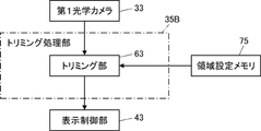
- FIG. 11 is a block diagram of one embodiment showing the configuration of a trimming processing unit of the ultrasonic diagnostic apparatus of the second embodiment; 9 is a flow chart of one embodiment showing the operation of the ultrasonic diagnostic apparatus of the second embodiment;
- FIG. 11 is a block diagram of a third embodiment showing the configuration of an ultrasonic diagnostic apparatus according to the present invention;
- FIG. 11 is a block diagram of one embodiment showing the configuration of a trimming processing unit of an ultrasonic diagnostic apparatus according to a third embodiment;
- 1 is a conceptual diagram of one embodiment of a standard optical image captured by a standard camera;
- FIG. 1 is a conceptual diagram of one embodiment of a wide-angle optical image captured by a wide-angle camera;
- FIG. 11 is a block diagram of one embodiment showing the configuration of a trimming processing unit of an ultrasonic diagnostic apparatus according to a third embodiment;
- 1 is a conceptual diagram of one embodiment of a standard optical image captured by a standard camera;
- FIG. 1 is a conceptual diagram of one embodiment of a wide-angle optical image captured by a wide-angle camera;
- FIG. 1 is a block diagram of the first embodiment showing the configuration of the ultrasonic diagnostic apparatus of the present invention.
- the ultrasonic diagnostic apparatus shown in FIG. 1 is a handheld ultrasonic diagnostic apparatus, and includes an ultrasonic probe 1 and an apparatus body 3A connected to the ultrasonic probe 1.
- the ultrasonic diagnostic apparatus of this embodiment is realized by an ultrasonic probe 1, an apparatus main body 3A, and an application program for ultrasonic diagnosis that operates on the apparatus main body 3A.
- the ultrasonic probe 1 scans the inspection location of the subject with an ultrasonic beam and outputs sound ray signals corresponding to the ultrasonic image of this inspection location.
- the ultrasonic probe 1 includes a transducer array 11, a transmission/reception circuit 13, and a battery 15, as shown in FIG.
- the transducer array 11 and the transmitting/receiving circuit 13 are bidirectionally connected, and the transmitting/receiving circuit 13 is connected to a device controller 47 of the device main body 3A, which will be described later.
- the transducer array 11 has a plurality of ultrasonic transducers arranged one-dimensionally or two-dimensionally. These transducers transmit ultrasonic waves in accordance with drive signals supplied from the transmission/reception circuit 13, receive reflected waves from the subject, and output analog reception signals.
- Each vibrator includes, for example, a piezoelectric ceramic typified by PZT (Lead Zirconate Titanate), a polymeric piezoelectric element typified by PVDF (Poly Vinylidene Di Fluoride), and PMN-PT ( Lead Magnesium Niobate-Lead Titanate: A piezoelectric single crystal represented by lead magnesium niobate-lead titanate solid solution).
- the transmission/reception circuit 13 causes the transducer array 11 to transmit an ultrasonic beam, and performs reception focusing processing on the reception signal output from the transducer array 11 that has received the ultrasonic echo.
- a sound ray signal is generated by applying.
- the transmission/reception circuit 13 includes a pulser 51 connected to the transducer array 11, an amplifier 53 connected in series from the transducer array 11, an AD (Analog Digital) converter 55, and a beamformer 53. 57 and .
- the pulsar 51 includes, for example, a plurality of pulse generators, and ultrasonic waves transmitted from a plurality of transducers of the transducer array 11 generate ultrasonic beams based on a transmission delay pattern selected by the device control unit 47.
- a transmission focus process is performed to adjust the amount of delay and supply each drive signal to a plurality of transducers so as to form a signal.
- the piezoelectric body expands and contracts, and pulse-shaped or continuous-wave ultrasonic waves are generated from the respective transducers. Then, an ultrasonic beam is formed from the composite wave of those ultrasonic waves.
- the transmitted ultrasonic beam is reflected by an object such as a part of the subject and propagates toward the transducer array 11 of the ultrasonic probe 1 .
- Each transducer constituting the transducer array 11 expands and contracts upon receiving the ultrasonic echo propagating toward the transducer array 11 in this way, generates a reception signal that is an electrical signal, and receives these signals.
- a signal is output to the amplifier 53 .
- the amplification unit 53 amplifies the signal input from each transducer that constitutes the transducer array 11 and transmits the amplified signal to the AD conversion unit 55 .
- the AD converter 55 converts the analog signal transmitted from the amplifier 53 into digital reception data and outputs the reception data to the beamformer 57 .
- the beamformer 57 gives respective delays to the received data converted by the AD converter 55 according to the sound velocity or the distribution of the sound velocity set based on the reception delay pattern selected by the device controller 47, and adds them. receive focus processing. By this reception focus processing, each reception data converted by the AD conversion unit 55 is phased and added, and an acoustic ray signal in which the focus of the ultrasonic echo is narrowed down is generated.
- the battery 15 is built in the ultrasonic probe 1 and supplies power to each circuit of the ultrasonic probe 1 .
- the apparatus main body 3A generates an ultrasonic image including the examination location of the subject based on the sound ray signal generated by the ultrasonic probe 1, and displays the ultrasonic image including the examination location of the subject. do.
- the device main body 3A is, for example, a handheld terminal device such as a smartphone or a tablet PC (Personal Computer), and as shown in FIG. , a trimming processor 35 A, a monitor 41 , a display controller 43 , an input device 45 and a device controller 47 .
- the ultrasonic image generation unit 31 is connected to the transmission/reception circuit 13 of the ultrasonic probe 1, and the display control unit 43 and the monitor 41 are sequentially connected to the ultrasonic image generation unit 31.
- a trimming processing unit 35A and a display control unit 43 are sequentially connected to the first optical camera 33 .
- a device control unit 47 is connected to the ultrasonic image generation unit 31 , the first optical camera 33 , the trimming processing unit 35A and the display control unit 43 , and the device control unit 47 is connected to the input device 45 .
- the ultrasonic probe 1 and the device main body 3A are connected wirelessly by wireless communication such as Wi-Fi (Wireless Fidelity), or by using a USB (Universal Serial Bus) cable or the like. are connected by wire through wired communication.
- wireless communication such as Wi-Fi (Wireless Fidelity), or by using a USB (Universal Serial Bus) cable or the like.
- USB Universal Serial Bus
- the ultrasonic image generation unit 31 uses the ultrasonic probe 1 (more precisely, the transducer array 11) to transmit and receive ultrasonic beams to and from the examination site of the subject.
- An ultrasonic image (ultrasonic image signal) including the inspected part of the subject is generated from the received signal obtained by the transmission/reception circuit 13, or more specifically, from the sound ray signal generated from the received signal by the transmission/reception circuit 13.
- FIG. 3 the ultrasonic image generating section 31 has a configuration in which a signal processing section 21, a DSC 23 and an image processing section 25 are sequentially connected in series.
- the signal processing unit 21 generates image information data corresponding to the ultrasonic image based on the acoustic ray signal generated by the transmission/reception circuit 13 . More specifically, the signal processing unit 21 performs signal processing on the sound ray signal generated by the beamformer 57 of the transmission/reception circuit 13, for example, attenuation due to the propagation distance according to the depth of the position where the ultrasonic wave is reflected. After performing the correction of , envelope detection processing is performed to generate image information data representing tomographic image information regarding tissue in the subject.
- a DSC (Digital Scan Converter) 23 raster-converts the image information data generated by the signal processing unit 21 into an image signal that conforms to the normal television signal scanning method.
- the image processing unit 25 performs various corrections such as brightness correction, gradation correction, sharpness correction, image size correction, refresh rate correction, scanning frequency correction, and color correction on the image signal input from the DSC 23 according to the display format of the monitor 41 .
- An ultrasonic image is generated by performing the image processing of , and the ultrasonic image subjected to the image processing is output to the display control unit 43 .
- the first optical camera 33 generates various optical images under the control of the device control section 47 .
- the first optical camera 33 is arranged on the other surface (rear surface) of the apparatus main body 3A opposite to the one surface (front surface) of the apparatus main body 3A.
- the first optical camera 33 captures an image of the subject including the ultrasonic probe 1 that is inspecting the inspection location, thereby generating an optical image of the subject in a state where the ultrasonic probe 1 is in contact with the inspection location. can do.
- the trimming processor 35A performs various processes for generating a trimmed image from the optical image generated by the first optical camera 33 under the control of the device controller 47 .
- the trimming processing unit 35A has a probe recognition unit 61, a trimming unit 63, and a notification unit 65, as shown in FIG.
- the probe recognition section 61 is connected to the first optical camera 33 .
- a trimming unit 63 and a notification unit 65 are connected to the probe recognition unit 61
- a display control unit 43 is connected to the trimming unit 63 and the notification unit 65 .
- a probe recognition unit 61 recognizes the ultrasonic probe 1 from the optical image generated by the first optical camera 33 .
- the probe recognition unit 61 recognizes, for example, whether or not the ultrasonic probe 1 is included in the optical image, in other words, whether or not the ultrasonic probe 1 is shown in the optical image. Further, when the probe recognition unit 61 recognizes that the ultrasonic probe 1 is included in the optical image, the area of the ultrasonic probe 1 in the optical image, in other words, the ultrasonic probe 1 is shown in the optical image. Recognize range.
- the method of recognizing the ultrasonic probe 1 is not particularly limited as long as the ultrasonic probe 1 can be recognized from the optical image.
- the probe recognition unit 61 can recognize the ultrasonic probe 1 from the optical image by, for example, identifying the ultrasonic probe 1 included in the optical image by image recognition processing.
- the probe recognition unit 61 can use, for example, a determination model based on machine learning as image recognition processing for recognizing the ultrasonic probe 1 from an optical image.
- the determination model uses a learning optical image including an ultrasonic probe in contact with an inspection location of a subject as teacher data, and the relationship between the learning optical image and the ultrasonic probe included in this learning optical image. is a trained model trained on multiple teacher data. Based on the learning result, the determination model receives an optical image to be determined, and outputs a determination result (prediction result) of the ultrasonic probe included in this optical image. The probe recognition unit 61 recognizes the ultrasonic probe 1 from the optical image based on the determination result of the determination model.
- the trimming unit 63 When the probe recognition unit 61 recognizes the ultrasonic probe 1 from the optical image, the trimming unit 63 generates a trimmed image by trimming an area including the ultrasonic probe 1 from the optical image, for example, a rectangular area. do.
- the trimmed image is not particularly limited as long as the user (examiner) of the ultrasonic diagnostic apparatus can identify the position and orientation of the ultrasonic probe 1 from the trimmed image.
- the ultrasonic probe 1 appearing in the trimmed image is magnified more than the ultrasonic probe 1 appearing in the optical image. .
- the notification unit 65 notifies that the ultrasonic probe 1 is not recognized when the ultrasonic probe 1 is not recognized from the optical image by the probe recognition unit 61, in other words, until the ultrasonic probe 1 is recognized from the optical image. is notified to the user.
- the notification method is not particularly limited, but for example, a message indicating that the ultrasonic probe 1 is not recognized is output from the notification unit 65 to the display control unit 43, and the display control unit 43 displays this message on the monitor 41.
- This message can be output from the notification unit 65 to a speaker (not shown), and the speaker can output the read-out voice of the message, or both can be performed at the same time.
- the number of notifications is not particularly limited, but for example, it may be notified only once, or it may be notified at regular intervals, or it may be notified until the ultrasonic probe 1 is recognized. You can let us know in the meantime.
- the display control unit 43 causes the monitor 41 to display various information under the control of the device control unit 47 .
- a monitor (display unit) 41 displays various types of information under the control of a display control unit 43 .
- the monitor 41 simultaneously displays, for example, the ultrasonic image generated by the ultrasonic image generator 31 and the optical image generated by the first optical camera 33 or its trimmed image.
- the monitor 41 is arranged on one side of the device body 3A, that is, on the side of the device body 3A opposite to the first optical camera 33 .
- the monitor 41 is not particularly limited, but for example, an LCD (Liquid Crystal Display) and an organic EL (Electro-Luminescence) display can be exemplified.
- the input device 45 receives various instructions input by the user.
- the input device 45 is not particularly limited, but includes, for example, various buttons and a touch panel through which a user performs touch operations to input various instructions.
- the device control unit 47 controls each part of the ultrasonic probe 1 and the device main body 3A based on a program stored in advance and user's instructions input from the input device 45 .
- the ultrasonic image generation unit 31, the trimming processing unit 35A, the display control unit 43, and the device control unit 47 are configured by a processor 49A in the case of this embodiment.
- the user When inspecting a subject, first, as shown in FIG. 6, the user starts scanning the inspection location while the ultrasonic probe 1 is in contact with the inspection location of the subject, and moves the first optical camera 33 is used to image the subject including the ultrasound probe 1 under examination at the examination site.
- FIG. 6 is a conceptual diagram of an embodiment showing how the user is examining the abdomen of the subject.
- the subject lies face up on an examination table as shown in FIG.
- the user scans the abdomen of the subject by holding the ultrasound probe 1 in the right hand and transmitting and receiving ultrasonic waves while the ultrasound probe 1 is in contact with the abdomen of the subject.
- An optical camera 33 is used to image the subject including the ultrasound probe 1 during examination of the abdomen.
- the transmitting/receiving circuit 13 transmits/receives ultrasonic waves under the control of the device control unit 47 while the ultrasonic probe 1 is in contact with the inspection site of the subject (step S1), and the sound ray signal is transmitted. generated.
- ultrasonic beams are transmitted from the plurality of transducers of the transducer array 11 to the inspected portion of the subject according to the drive signal from the pulser 51 .
- An ultrasonic echo from an inspection location based on an ultrasonic beam transmitted from the pulsar 51 is received by each transducer of the transducer array 11, and each transducer of the transducer array 11 that has received the ultrasonic echo outputs an analog signal.
- a received signal is output.
- a reception signal output from each transducer of the transducer array 11 is amplified by the amplification unit 53 and AD-converted by the AD conversion unit 55 to obtain reception data.
- a sound ray signal is generated by subjecting the received data to reception focusing processing by the beamformer 57 .
- the ultrasonic image generation unit 31 generates an ultrasonic image including the examination location of the subject based on the acoustic ray signal generated by the beamformer 57 of the transmission/reception circuit 13 under the control of the device control unit 47. generated (step S2).
- the sound ray signal generated by the beamformer 57 is subjected to various signal processing by the signal processing unit 21 to generate image information data representing tomographic image information regarding tissues in the subject.
- the image information data generated by the signal processing unit 21 is raster-converted by the DSC 23 and subjected to various image processing by the image processing unit 25 to sequentially generate ultrasonic images (moving images).
- the first optical camera 33 captures an image of the subject including the ultrasonic probe 1 that is currently inspecting the inspection site, and the ultrasonic probe 1 is in contact with the inspection site.
- Optical images (moving images) including the subject are sequentially generated (step S3).
- an ultrasonic image including the inspection location of the subject and an optical image of the subject including the ultrasound probe 1 currently inspecting the inspection location are sequentially generated at the same time.
- the display control unit 43 controls the ultrasonic image generated by the ultrasonic image generating unit 31 and the optical image generated by the first optical camera 33 as shown in FIG. 7 under the control of the device control unit 47 . Images are sequentially displayed on the monitor 41 (step S4).
- the user scans the examination site of the subject using the ultrasonic probe 1 while viewing the ultrasonic image and the optical image displayed on the display screen of the monitor 41 arranged on one side of the apparatus main body 3A.
- the ultrasonic probe 1 is imaged to image the subject in contact with the inspection location, and optically Images can be generated.
- the trimming processing section 35A performs various processes for generating a trimmed image from the optical image.
- the probe recognition unit 61 recognizes the ultrasonic probe 1 from the optical image generated by the first optical camera 33 (step S5). As a result, when the ultrasonic probe 1 is not recognized from the optical image (No in step S6), the display control unit 43 continues to sequentially display the ultrasonic image and the optical image on the monitor 41 (step S7). Further, when the ultrasonic probe 1 is not recognized, the notification unit 65 notifies the user that the ultrasonic probe 1 is not recognized. After that, the process returns to step S5.
- the trimming unit 63 when the ultrasonic probe 1 is recognized from the optical image (Yes in step S6), the trimming unit 63 generates a trimmed image by trimming the area including the ultrasonic probe 1 from the optical image (step S8 ).
- the size of the ultrasonic probe 1 reflected in the trimmed image is larger than the size of the ultrasonic probe 1 reflected in the optical image, and the tip of the ultrasonic probe 1 becomes the central portion of the trimmed image.
- the notification by the notification unit 65 is stopped.
- the display control unit 43 sequentially displays the trimmed image generated by the trimming unit 63 instead of the ultrasonic image and the optical image on the monitor 41 as shown in FIG. step S9).
- the user while viewing the ultrasonic image and the trimmed image sequentially displayed on the monitor 41 of the apparatus main body 3A, the user, for example, at the timing at which the user thinks that the desired ultrasonic image including the examination location of the subject has been generated. Press the freeze button (not shown).
- both the ultrasonic image and the optical image are frozen by the device control section 47 (step S10).
- the device control unit 47 may perform control so that at least one of the ultrasonic image and the optical image is frozen when the freeze button is pressed.
- the display control unit 43 displays on the monitor 41 an ultrasonic image (still image) and an optical image (still image) generated at the timing when freeze is specified by the user. and stored in an image memory (not shown).
- the monitor 41 displays an ultrasonic image and a trimmed image generated by trimming an area including the ultrasonic probe 1 under inspection from an optical image. be. Therefore, the user can easily grasp the position and orientation of the ultrasonic probe 1 at the time of generation of the ultrasonic image during inspection of the inspection site of the subject by viewing the trimmed image in which the ultrasonic probe 1 is enlarged. be able to.
- FIG. 9 is a block diagram of a second embodiment showing the configuration of the ultrasonic diagnostic apparatus of the present invention.
- the ultrasonic diagnostic apparatus shown in FIG. 9 includes an ultrasonic probe 1 and an apparatus body 3B connected to the ultrasonic probe 1.
- the device main body 3B includes an ultrasonic image generation unit 31, a first optical camera 33, a trimming processing unit 35B, an area setting memory 75, a monitor 41, a display control unit 43, an input device 45, and a device A control unit 47 is provided. That is, the ultrasonic diagnostic apparatus of the second embodiment further includes a region setting memory 75 and a trimming processor 35B instead of the trimming processor 35A in addition to the ultrasonic diagnostic apparatus of the first embodiment.
- trimming processing unit 35B and the area setting memory 75 will be mainly described, and the same components as those of the ultrasonic diagnostic apparatus of the first embodiment will be given the same reference numerals, and repeated description thereof will be omitted.
- a trimming processor 35B and a display controller 43 are sequentially connected to the first optical camera 33 .
- the trimming processing section 35B and the device control section 47 are connected to the area setting memory 75 .
- the trimming processing unit 35B performs various processes for generating a trimmed image from the optical image generated by the first optical camera 33 under the control of the device control unit 47.
- the trimming processing section 35B has a trimming section 63, as shown in FIG.
- the trimming section 63 is connected to the first optical camera 33 and the area setting memory 75
- the display control section 43 is connected to the trimming section 63 .
- the area setting memory 75 stores, under the control of the device control unit 47, one preset area out of the multiple areas in the optical image divided into the preset multiple areas.
- the region setting memory 75 stores, for example, which range each of a plurality of preset regions corresponds to in the optical image, and one preset region corresponds to the plurality of regions. It memorizes which area of .
- the method of dividing the optical image is not particularly limited.
- the horizontally elongated optical image is horizontally divided into two areas, left and right, or divided into two areas. It can be divided into three areas, middle and right.
- the vertically elongated optical image is divided in the vertical direction, for example, into two equal areas, upper and lower, or into three areas, upper, middle, and lower. can be divided.
- the ultrasonic image generation unit 31, the trimming processing unit 35B, the display control unit 43 and the device control unit 47 are configured by the processor 49B.
- the user holds the ultrasonic probe 1 with the right hand to scan the abdomen of the subject, and at the same time, holds the device body 3B with the left hand to scan the subject including the ultrasonic probe 1 under examination of the abdomen.
- the area setting memory 75 stores a horizontally long optical image divided into three areas, left, middle, and right, as a plurality of preset areas. Assume that the right area is stored as one set area.
- steps S11 to S13 of the ultrasonic diagnostic apparatus of the second embodiment are the same as the operations of steps S1 to S3 of the ultrasonic diagnostic apparatus of the first embodiment shown in the flowchart of FIG.
- the trimming processing section 35B performs various processes for generating a trimmed image from the optical image. That is, in the horizontally elongated optical image divided into three regions of left, middle, and right stored in the region setting memory 75 by the trimming unit 63, by trimming the right region out of these three regions, A trimmed image is generated (step S14).
- steps S15 to S16 of the ultrasonic diagnostic apparatus of the second embodiment are the same as the operations from steps S9 to S10 of the ultrasonic diagnostic apparatus of the first embodiment shown in the flowchart of FIG.
- the user holds the ultrasonic probe 1 with the right hand to scan the abdomen of the subject, and at the same time, holds the device body 3B with the left hand to scan the subject including the ultrasonic probe 1 under examination of the abdomen.
- the ultrasonic probe 1 is captured in the right area of the horizontally long optical image. Therefore, in this case, by trimming the right region in the optical image, the region including the ultrasonic probe 1 can be trimmed. Effects similar to those of the ultrasonic diagnostic apparatus of the first embodiment can be obtained.
- the ultrasonic probe 1 can be trimmed by setting in advance the left area in the optical image to be trimmed.
- the ultrasonic probe 1 is often captured in the area below the vertically elongated optical image. . Therefore, in this case, the area including the ultrasonic probe 1 can be trimmed by setting in advance to trim the lower area in the optical image.
- FIG. 12 is a block diagram of a third embodiment showing the configuration of the ultrasonic diagnostic apparatus of the present invention.
- the ultrasonic diagnostic apparatus shown in FIG. 12 includes an ultrasonic probe 1 and an apparatus body 3C connected to the ultrasonic probe 1.
- the device main body 3C includes an ultrasonic image generation unit 31, a first optical camera 33, a second optical camera 67, a third optical camera 69, a trimming processing unit 35C, a monitor 41, and a display control unit 43. , an input device 45 , and a device control section 47 . That is, the ultrasonic diagnostic apparatus of the third embodiment further includes a second optical camera 67 and a third optical camera 69 in addition to the ultrasonic diagnostic apparatus of the first embodiment, and instead of the trimming processing unit 35A, A trimming processing unit 35C is provided.
- a trimming processor 35C is connected to the first optical camera 33, the second optical camera 67, and the third optical camera 69. As shown in FIG. A device control section 47 is connected to the first optical camera 33, the second optical camera 67, the third optical camera 69 and the trimming processing section 35C.
- the second optical camera 67 Under the control of the device control unit 47, the second optical camera 67 generates various optical images with angles of view different from those of the first optical camera 33.
- the second optical camera 67 is arranged on the other surface of the device body 3C. That is, the first optical camera 33 and the second optical camera 67 are arranged on the same side surface of the device body 3C.
- the second optical camera 67 captures an image of the subject including the ultrasonic probe 1 that is inspecting the inspection location, thereby capturing the state in which the ultrasonic probe 1 is in contact with the inspection location.
- An optical image can be generated that includes the subject.
- the first optical camera 33 is a standard camera that generates, for example, the standard optical image shown in FIG. 14 by capturing an image of the subject with a first angle of view.
- the device body 3C has a plurality of optical cameras having different angles of view from each other, including the first optical camera 33 and the second optical camera 67 .
- the device main body 3C is not limited to the first optical camera 33 and the second optical camera 67, and may have two or more optical cameras with different angles of view.
- the third optical camera 69 generates various optical images under the control of the device control section 47.
- the third optical camera 69 is arranged on one side of the device body 3C. That is, the third optical camera 69 and the monitor 41 are arranged on the same side surface of the device body 3C. In other words, the third optical camera 69, the first optical camera 33 and the second optical camera 67 are arranged on opposite sides of the device body 3C.
- the third optical camera 69 can generate an optical image including the user's eyes, for example, by capturing an image of the user.
- the third optical camera 69 like the first optical camera 33, images the subject including the ultrasonic probe 1 under inspection at the inspection location, so that the ultrasonic probe 1 is brought into contact with the inspection location.
- An optical image can also be generated that includes the subject of the condition.
- the trimming processor 35C generates a trimmed image from an optical image generated by any one of the first optical camera 33, the second optical camera 67 and the third optical camera 69 under the control of the device controller 47. perform various processing for
- the trimming processing unit 35C has an optical camera selection unit 71, a probe recognition unit 61, a trimming unit 63, a notification unit 65, and a line-of-sight recognition unit 73, as shown in FIG.
- An optical camera selection unit 71 is connected to the first optical camera 33 , the second optical camera 67 and the third optical camera 69 , and the probe recognition unit 61 is connected to the optical camera selection unit 71 .
- the trimming unit 63 , the notification unit 65 and the line-of-sight recognition unit 73 are connected to the probe recognition unit 61 , and the display control unit 43 is connected to the trimming unit 63 , the notification unit 65 and the line-of-sight recognition unit 73 .
- the optical camera selection unit 71 selects one or more optical cameras, or an optical Select an imaging mode that supports the camera.
- the line-of-sight recognition unit 73 recognizes the user's line of sight based on the optical image including the user's eyes generated by the third optical camera 69 .
- the line-of-sight recognition unit 73 recognizes whether or not a preset line-of-sight action has been recognized, for example, whether or not the user has winked.
- the method for recognizing the line of sight is not particularly limited as long as the line of sight of the user can be recognized from the optical image, and various conventionally known methods can be used.
- the preset line-of-sight motion is not limited to wink, and various types of line-of-sight motion can be set.
- the ultrasonic image generation unit 31, the trimming processing unit 35C, the display control unit 43, and the device control unit 47 are configured by a processor 49C in the case of this embodiment.
- a user can select one or more optical cameras or imaging modes from a plurality of optical cameras.
- the optical camera selection unit 71 selects one optical camera from among the plurality of optical cameras based on an instruction from the user.
- the first optical camera (standard camera) 35 When the first optical camera (standard camera) 35 is selected, the first optical camera 33 is used to image the subject, including the ultrasonic probe 1 under inspection, to generate a standard optical image. It will be in shooting mode.
- the second optical camera (wide-angle camera) 67 When the second optical camera (wide-angle camera) 67 is selected, the second optical camera 67 is used to image the subject including the ultrasonic probe 1 under inspection to generate a wide-angle optical image. It will be in shooting mode.
- the standard imaging mode and the wide-angle imaging mode for example, as shown in FIG. 6, the user scans the abdomen of the subject by holding the ultrasonic probe 1 with the right hand, and at the same time holding the device main body 3C with the left hand. The subject is imaged using the first optical camera 33 .
- the third optical camera 69 is used to capture an image of the subject including the ultrasonic probe 1 that is being inspected, thereby generating an optical image.
- the user for example, leans the device main body 3C against a fixing tool such as a stand and places it fixedly on the far side of the subject, holds the ultrasonic probe 1 with the right hand, and holds the subject. scan the abdomen of
- the third optical camera of the device main body 3C which is fixedly arranged, is used to capture an image of the subject including the ultrasonic probe 1 that is currently being inspected.
- the probe recognition unit 61 recognizes the ultrasonic probe 1 from an optical image generated by one optical camera selected by the optical camera selection unit 71. be done. Then, the trimming unit 63 generates a trimmed image from the optical image generated by the same single optical camera.
- the first optical camera 33 and the second optical camera 67 may be arranged on one surface (front surface) of the device body 3C, ie, the surface of the device body 3C on the same side as the monitor 41 .
- at least one of the first optical camera 33 and the second optical camera 67 is used to capture an image of the subject in a state in which the device main body 3C is leaned against a fixture such as a stand and arranged on the far side of the subject. can be done.
- a plurality of optical cameras having different angles of view including the third optical camera 69 and a fourth optical camera (not shown), may be arranged on one surface of the device body 3C. In this case, even in the fixed imaging mode, the optical camera to be used can be selected from a plurality of optical cameras having different angles of view.
- the optical camera selection unit 71 simultaneously selects two or more optical cameras from among the plurality of optical cameras based on an instruction from the user.
- a simultaneous imaging mode is entered in which optical images are simultaneously generated by imaging the subject including the ultrasonic probe 1 under inspection at the inspection site using the selected two or more optical cameras.
- the standard optical image is generated using the first optical camera (standard camera) 33 and at the same time the second optical camera (wide-angle camera) 67 is is used to generate a wide-angle optical image.
- the probe recognition unit 61 recognizes the ultrasonic probe 1 from the standard optical image and the wide-angle optical image. Since the wide-angle optical image has a wider angle of view than the standard optical image and there is a high possibility that the ultrasonic probe 1 is captured in the wide-angle optical image, the probe recognition unit 61 first detects the ultrasonic probe 1 from the wide-angle optical image.
- the ultrasound probe 1 can be recognized from the standard optical image only if the ultrasound probe 1 is recognized from the wide-angle optical image.
- the probe recognition unit 61 can recognize the ultrasonic probe 1 from each of the wide-angle optical image and the standard optical image regardless of whether the ultrasonic probe 1 is recognized from the wide-angle optical image.
- the standard optical image generally has higher image quality than the wide-angle optical image.
- a cropped image is generated from the optical image.
- the trimming unit 63 generates a trimmed image from the wide-angle optical image.
- the user can select a desired optical camera from among a plurality of optical cameras, and an optical image is generated using the optical camera selected by the user. can do.
- the ultrasonic diagnostic apparatus of this embodiment it is possible to instruct freezing using the user's line of sight.
- the user is imaged by the third optical camera 69 arranged on the surface of the device main body 3C on the same side as the monitor 41, and an optical image including the user's eyes is generated.
- the line of sight of the user is recognized by the line of sight recognition unit 73 based on the optical image generated by the third optical camera 69 .
- the device control unit 47 freezes both the ultrasonic image and the optical image.
- the freeze instruction may be given using the user's voice.
- the keyword uttered by the user is recognized by a voice recognition unit (not shown).
- the device control section 47 freezes both the ultrasonic image and the optical image. In this way, the user can easily give a freeze instruction by using the line of sight or voice.
- the device control unit 47 may control to freeze both the ultrasonic image and the optical image at the same time as described above, but controls to freeze at least one of the ultrasonic image and the optical image.
- ultrasonic diagnostic apparatuses of the first, second, and third embodiments have been described, these embodiments may be implemented independently or in combination.
- the area setting memory 75 of the ultrasonic diagnostic apparatus of the second embodiment may be provided to divide the optical image into a plurality of areas.
- the probe recognition unit 61 may recognize the ultrasonic probe 1 from only one of the plurality of regions, and the trimming unit 63 may generate a trimmed image from only the same region. good.
- the device bodies 3A and 3B of the ultrasonic diagnostic devices of the first and second embodiments are not limited to the first optical camera 33, and may be provided with at least one optical camera.
- the device main bodies 3A and 3B may be provided with a plurality of optical cameras having different angles of view according to the third embodiment, and one or more optical cameras may be selected from among the plurality of optical cameras based on an instruction from the user. good.
- the probe recognition unit 61 recognizes the ultrasonic probe 1 from the optical image generated by at least one optical camera
- the trimming unit 63 recognizes the probe recognition from the optical image generated by the at least one optical camera. A region including the ultrasonic probe is trimmed from one optical image in which the ultrasonic probe 1 is recognized by the unit 61 .
- the user may use the input device 45 to set the trimming region in the optical image displayed on the monitor 41 .
- the probe recognition unit 61 recognizes the ultrasonic probe 1 only from the trimming area set based on the user's instruction in the optical image. Then, the trimming section 63 generates a trimming image only from this trimming area.
- the probe recognition unit 61 preferably recognizes the ultrasonic probe 1 held by the user from the optical image. By recognizing the ultrasonic probe 1 held by the user's hand, the ultrasonic probe 1 under inspection can be detected without erroneous recognition even if a plurality of ultrasonic probes are shown in the optical image. can be recognized correctly.
- the trimming unit 63 obtains the position and orientation of the ultrasonic probe 1 and the position and orientation of the ultrasonic probe 1 under examination from the optical image. It is desirable to generate a cropped image by cropping, for example, a rectangular area that includes the subject within a range whose orientation can be specified.
- the device main bodies 3A, 3B, and 3C may include the ultrasonic image generation unit 31, the ultrasonic image generation unit 31 is not limited to this, and the entire ultrasonic image generation unit 31 or only the signal processing unit 21 may be provided on the ultrasonic probe 1 side. may
- a processing unit that executes various processes such as the transmission/reception circuit 13, the ultrasonic image generation unit 31, the trimming processing units 35A, 35B, and 35C, the display control unit 43, and the device control unit 47
- the hardware configuration may be dedicated hardware, or may be various processors or computers that execute programs.
- a semiconductor memory may be used, or a recording medium such as a flash memory, an SD card (Secure Digital card), a USB memory (Universal Serial Bus memory) may be used.
- an HDD Hard Disk Drive
- SSD Solid State Drive
- an external server or the like can also be used.
- the circuit configuration can be changed after manufacturing such as CPU (Central Processing Unit), FPGA (Field Programmable Gate Array), etc., which are general-purpose processors that run software (programs) and function as various processing units.
- Programmable Logic Device PLD
- ASIC Application Specific Integrated Circuit
- One processing unit may be composed of one of these various processors, or a combination of two or more processors of the same or different type, such as a combination of multiple FPGAs, or a combination of FPGAs and CPUs. and so on. Also, the plurality of processing units may be configured by one of various processors, or two or more of the plurality of processing units may be combined into one processor.
- SoC System on Chip
- the hardware configuration of these various processors is, more specifically, an electric circuit that combines circuit elements such as semiconductor elements.
- the method of the present invention can be implemented, for example, by a program for causing a computer to execute each step. It is also possible to provide a computer-readable recording medium on which this program is recorded.
Landscapes
- Life Sciences & Earth Sciences (AREA)
- Health & Medical Sciences (AREA)
- Biomedical Technology (AREA)
- Biophysics (AREA)
- Nuclear Medicine, Radiotherapy & Molecular Imaging (AREA)
- Pathology (AREA)
- Radiology & Medical Imaging (AREA)
- Engineering & Computer Science (AREA)
- Physics & Mathematics (AREA)
- Heart & Thoracic Surgery (AREA)
- Medical Informatics (AREA)
- Molecular Biology (AREA)
- Surgery (AREA)
- Animal Behavior & Ethology (AREA)
- General Health & Medical Sciences (AREA)
- Public Health (AREA)
- Veterinary Medicine (AREA)
- Ultra Sonic Daignosis Equipment (AREA)
Priority Applications (2)
| Application Number | Priority Date | Filing Date | Title |
|---|---|---|---|
| JP2023508944A JPWO2022202289A1 (https=) | 2021-03-26 | 2022-03-08 | |
| US18/468,339 US20240000439A1 (en) | 2021-03-26 | 2023-09-15 | Ultrasound diagnostic apparatus and control method for ultrasound diagnostic apparatus |
Applications Claiming Priority (2)
| Application Number | Priority Date | Filing Date | Title |
|---|---|---|---|
| JP2021-052639 | 2021-03-26 | ||
| JP2021052639 | 2021-03-26 |
Related Child Applications (1)
| Application Number | Title | Priority Date | Filing Date |
|---|---|---|---|
| US18/468,339 Continuation US20240000439A1 (en) | 2021-03-26 | 2023-09-15 | Ultrasound diagnostic apparatus and control method for ultrasound diagnostic apparatus |
Publications (1)
| Publication Number | Publication Date |
|---|---|
| WO2022202289A1 true WO2022202289A1 (ja) | 2022-09-29 |
Family
ID=83397085
Family Applications (1)
| Application Number | Title | Priority Date | Filing Date |
|---|---|---|---|
| PCT/JP2022/009978 Ceased WO2022202289A1 (ja) | 2021-03-26 | 2022-03-08 | 超音波診断装置および超音波診断装置の制御方法 |
Country Status (3)
| Country | Link |
|---|---|
| US (1) | US20240000439A1 (https=) |
| JP (1) | JPWO2022202289A1 (https=) |
| WO (1) | WO2022202289A1 (https=) |
Families Citing this family (1)
| Publication number | Priority date | Publication date | Assignee | Title |
|---|---|---|---|---|
| JP2025080496A (ja) * | 2023-11-14 | 2025-05-26 | コニカミノルタ株式会社 | 超音波診断支援装置、超音波診断装置、超音波診断支援方法及びプログラム |
Citations (3)
| Publication number | Priority date | Publication date | Assignee | Title |
|---|---|---|---|---|
| JP2006000400A (ja) * | 2004-06-17 | 2006-01-05 | Shimadzu Corp | 超音波診断装置 |
| JP2007282792A (ja) * | 2006-04-14 | 2007-11-01 | Matsushita Electric Ind Co Ltd | 超音波診断装置 |
| JP2018057428A (ja) * | 2016-09-30 | 2018-04-12 | キヤノンメディカルシステムズ株式会社 | 超音波診断装置および超音波診断支援プログラム |
Family Cites Families (6)
| Publication number | Priority date | Publication date | Assignee | Title |
|---|---|---|---|---|
| WO2014189969A1 (en) * | 2013-05-21 | 2014-11-27 | Camplex, Inc. | Surgical visualization systems |
| KR102258800B1 (ko) * | 2014-05-15 | 2021-05-31 | 삼성메디슨 주식회사 | 초음파 진단장치 및 그에 따른 초음파 진단 방법 |
| US9436993B1 (en) * | 2015-04-17 | 2016-09-06 | Clear Guide Medical, Inc | System and method for fused image based navigation with late marker placement |
| US9949798B2 (en) * | 2016-01-06 | 2018-04-24 | Ethicon Endo-Surgery, Llc | Methods, systems, and devices for controlling movement of a robotic surgical system |
| WO2019064706A1 (ja) * | 2017-09-27 | 2019-04-04 | 富士フイルム株式会社 | 超音波診断装置および超音波診断装置の制御方法 |
| CN117062570A (zh) * | 2021-03-22 | 2023-11-14 | 皇家飞利浦有限公司 | 用于便携式超声方法和装置的基于深度学习的实时眼睛注视跟踪 |
-
2022
- 2022-03-08 WO PCT/JP2022/009978 patent/WO2022202289A1/ja not_active Ceased
- 2022-03-08 JP JP2023508944A patent/JPWO2022202289A1/ja active Pending
-
2023
- 2023-09-15 US US18/468,339 patent/US20240000439A1/en active Pending
Patent Citations (3)
| Publication number | Priority date | Publication date | Assignee | Title |
|---|---|---|---|---|
| JP2006000400A (ja) * | 2004-06-17 | 2006-01-05 | Shimadzu Corp | 超音波診断装置 |
| JP2007282792A (ja) * | 2006-04-14 | 2007-11-01 | Matsushita Electric Ind Co Ltd | 超音波診断装置 |
| JP2018057428A (ja) * | 2016-09-30 | 2018-04-12 | キヤノンメディカルシステムズ株式会社 | 超音波診断装置および超音波診断支援プログラム |
Also Published As
| Publication number | Publication date |
|---|---|
| US20240000439A1 (en) | 2024-01-04 |
| JPWO2022202289A1 (https=) | 2022-09-29 |
Similar Documents
| Publication | Publication Date | Title |
|---|---|---|
| JPWO2017033502A1 (ja) | 超音波診断装置および超音波診断装置の制御方法 | |
| JP6179290B2 (ja) | 超音波測定装置、超音波画像装置及び超音波測定装置の制御方法 | |
| US10912538B2 (en) | Ultrasound diagnostic apparatus and method of producing ultrasound image | |
| JP2015043835A (ja) | 超音波診断装置および超音波画像生成方法 | |
| US20240000439A1 (en) | Ultrasound diagnostic apparatus and control method for ultrasound diagnostic apparatus | |
| US20140187953A1 (en) | Ultrasound diagnostic apparatus, ultrasound image producing method, and recording medium | |
| JP7828496B2 (ja) | 超音波診断装置および超音波診断装置の表示方法 | |
| JP7794811B2 (ja) | 超音波診断装置および超音波診断装置の制御方法 | |
| WO2022230666A1 (ja) | 超音波診断装置および超音波診断装置の制御方法 | |
| WO2022244552A1 (ja) | 超音波診断装置および超音波診断装置の制御方法 | |
| WO2022196090A1 (ja) | 超音波診断装置および超音波診断装置の制御方法 | |
| US10788459B2 (en) | Ultrasound diagnostic apparatus, ultrasound image generation method, and recording medium | |
| JP7817985B2 (ja) | 超音波診断装置および超音波診断装置の制御方法 | |
| JP2020048928A (ja) | 超音波診断装置および超音波診断装置の制御方法 | |
| JP7821803B2 (ja) | 超音波診断装置および超音波診断装置の制御方法 | |
| JP7675738B2 (ja) | 超音波診断装置および超音波診断装置の表示方法 | |
| US12383231B2 (en) | Ultrasound diagnostic apparatus and control method of ultrasound diagnostic apparatus | |
| JP7784436B2 (ja) | 超音波診断装置および超音波診断装置の制御方法 | |
| JP2020048968A (ja) | 超音波診断装置および超音波診断装置の制御方法 | |
| JP7668291B2 (ja) | 超音波診断装置および超音波診断装置の制御方法 | |
| EP4193930A1 (en) | Ultrasound diagnostic apparatus and control method of ultrasound diagnostic apparatus | |
| JP2024025865A (ja) | 超音波診断装置の制御方法および超音波診断装置 | |
| WO2022202313A1 (ja) | 超音波診断装置および超音波診断装置の制御方法 | |
| JP2014226186A (ja) | 超音波測定装置及び超音波測定装置の制御方法 | |
| JP2006247039A (ja) | 超音波診断装置 |
Legal Events
| Date | Code | Title | Description |
|---|---|---|---|
| 121 | Ep: the epo has been informed by wipo that ep was designated in this application |
Ref document number: 22773399 Country of ref document: EP Kind code of ref document: A1 |
|
| WWE | Wipo information: entry into national phase |
Ref document number: 2023508944 Country of ref document: JP |
|
| NENP | Non-entry into the national phase |
Ref country code: DE |
|
| 122 | Ep: pct application non-entry in european phase |
Ref document number: 22773399 Country of ref document: EP Kind code of ref document: A1 |