WO2022202174A1 - 通信用電線 - Google Patents
通信用電線 Download PDFInfo
- Publication number
- WO2022202174A1 WO2022202174A1 PCT/JP2022/009045 JP2022009045W WO2022202174A1 WO 2022202174 A1 WO2022202174 A1 WO 2022202174A1 JP 2022009045 W JP2022009045 W JP 2022009045W WO 2022202174 A1 WO2022202174 A1 WO 2022202174A1
- Authority
- WO
- WIPO (PCT)
- Prior art keywords
- sheath
- wire
- polymer
- communication
- melting point
- Prior art date
- Legal status (The legal status is an assumption and is not a legal conclusion. Google has not performed a legal analysis and makes no representation as to the accuracy of the status listed.)
- Ceased
Links
Images


Classifications
-
- H—ELECTRICITY
- H01—ELECTRIC ELEMENTS
- H01B—CABLES; CONDUCTORS; INSULATORS; SELECTION OF MATERIALS FOR THEIR CONDUCTIVE, INSULATING OR DIELECTRIC PROPERTIES
- H01B11/00—Communication cables or conductors
Definitions
- This disclosure relates to communication wires.
- Patent Documents 1 and 2 disclose a twisted pair wire in which a pair of insulated wires made of a conductor and an insulating coating covering the outer periphery of the conductor are twisted together, A communication wire having a sheath made of an insulating material covering the outer periphery of a twisted pair wire is disclosed.
- Patent Documents 1 and 2 mainly deal with a form called a loose jacket type in which a gap is provided between a sheath and an insulated wire that constitutes a twisted pair wire.
- a communication wire having a sheath around the outer periphery of a signal wire including a plurality of insulated wires there is a loose jacket type wire having a gap between the sheath and the signal wire.
- a solid type in which substantially no gap is provided between the sheath and the communication wire, and the material of the sheath is brought into close contact with the surface of the insulated wire that constitutes the signal wire.
- the loose-jacket type and the solid-type have their own advantages, but the major advantage of the solid-type sheathed communication wire is that the signal line is held down from the outside by the sheath. It is possible to suppress relative position deviation such as loosening of the twisted structure.
- predetermined communication characteristics can be stably obtained by maintaining a predetermined relative arrangement of the multiple wires.
- a pair of insulated wires maintains a symmetrical positional relationship, so that the electromagnetic fields generated in each insulated wire cancel each other out, and the influence of electromagnetic noise from the outside can be reduced.
- the plurality of insulated wires that make up the signal line are held down by the sheath, thereby firmly maintaining the relative arrangement.
- the deviated relative arrangement is stably maintained as it is. , and it becomes difficult to obtain a predetermined communication characteristic.
- the twisted pair structure reduces the noise reduction effect.
- the solid sheath is formed by extrusion molding, a large pressure is applied to the insulated wire constituting the signal line by the molten resin composition. Then, due to the influence of heat and resin pressure, the insulated wires may be displaced or deformed relative to each other, and the insulated wires may be fixed by the sheath in this state.
- a communication wire having a solid sheath on the outer periphery of a signal wire including a plurality of insulated wires and when extruding the sheath, the insulated wire is affected by the influence of the molten resin composition.
- An object of the present invention is to provide a communication wire that is less likely to be misaligned or deformed.
- a communication wire includes a signal wire including a plurality of insulated wires each having a conductor and an insulating coating covering the outer circumference of the conductor, and a solid sheath covering the outer circumference of the signal wire.
- the composition constituting the sheath has a melt flow rate of 0.8 g/10 minutes or more and 2.1 g/10 minutes or less measured under a load of 2.16 kg at 230°C.
- a communication wire according to the present disclosure is a communication wire having a solid sheath on the outer periphery of a signal wire including a plurality of insulated wires, and when the sheath is extruded, the melted resin composition causes , the insulated wire is less likely to be displaced or deformed relative to the communication wire.
- FIG. 1 is a cross-sectional view showing the configuration of a communication wire according to one embodiment of the present disclosure.
- FIG. 2 is a schematic diagram showing the relationship between polymer temperature and fluidity. A solid line indicates a low melting point, and a dashed line indicates a high melting point.
- FIG. 3 is a cross-sectional view for explaining the definition of the degree of deformation of a core wire for a communication wire in which the deformation of the insulation coating has increased.
- FIG. 4 is a cross-sectional view for explaining the definition of the degree of filling of a communication wire with a low filling property of the sheath.
- FIG. 5 is a cross-sectional view for explaining the definition of the degree of heat deformation of a communication wire in which the sheath is greatly deformed by heat.
- a communication wire includes a signal wire including a plurality of insulated wires each having a conductor and an insulating coating covering the outer circumference of the conductor, and a solid sheath covering the outer circumference of the signal wire.
- the composition constituting the sheath has a melt flow rate of 0.8 g/10 minutes or more and 2.1 g/10 minutes or less measured under a load of 2.16 kg at 230°C.
- the sheath has a solid structure, and the material constituting the sheath is in close contact with the surface of the insulated wire that constitutes the signal line. has a melt flow rate of 0.8 g/10 minutes or more. Therefore, when the sheath is formed by extrusion molding, the area around the insulated wire is easily filled with the composition forming the sheath, and the pressure applied to the insulated wire can be reduced. As a result, the insulated wire is less likely to change in relative position or deform due to pressure during extrusion. In addition, since the composition that constitutes the sheath has high fluidity, the composition is likely to be densely filled at various locations around the signal wire, including the valleys between the plurality of insulated wires.
- the sheath firmly holds down the insulated wire in a state where the relative position is not changed or deformed, and it is easy to stably maintain the state where the relative position is not changed or deformed. As a result, it is possible to stably maintain communication characteristics obtained by a plurality of insulated wires having a predetermined relative arrangement. Furthermore, since the melt flow rate of the composition constituting the sheath is suppressed to 2.1 g/10 minutes or less at 230°C, the manufactured communication wire can be placed in a high temperature environment. The sheath is less likely to deform even under mechanical load. Therefore, deformation of the sheath is less likely to affect communication characteristics.
- the signal line is configured as a twisted pair wire in which a pair of the insulated wires are twisted together. Since the signal line is configured as a twisted pair, the relative positions of the pair of insulated wires are more stable than when the pair of insulated wires are arranged in parallel without being twisted together. easy to hold. Therefore, in combination with the effect of setting the lower limit of the melt flow rate of the composition constituting the sheath, when the sheath is manufactured by extrusion molding, the relative positions of the insulated wires are particularly unlikely to change. As a result, it is easy to maintain particularly favorable communication characteristics of the communication wire.
- Another member should not be provided between the sheath and the signal line. Since there is no other member such as a shielding metal foil, a metal braid, or a release agent layer between the sheath and the signal line, the structure of the communication wire is simplified. In this case, the insulated wire that constitutes the signal line is in direct contact with the sheath. It is possible to sufficiently suppress the influence on the communication characteristics due to deformation of the sheath and thermal deformation of the formed sheath.
- the sheath preferably contains a low melting point polymer having a melt flow rate of 15 g/10 minutes or more measured under a load of 2.16 kg at 230°C and a melting point of 140°C or more. Since the composition constituting the sheath contains a low-melting-point polymer having a low melting point and a high melt flow rate, insulation is achieved when the melted sheath composition is introduced around the outer periphery of the signal line and extrusion molding is performed. The composition can be densely packed under stable conditions while the coating is less likely to be displaced or deformed.
- the proportion of the low-melting polymer in the polymer components constituting the sheath is preferably larger than the proportion of the low-melting polymer in the polymer components constituting the insulating coating.
- the insulating coating is less likely to be deformed by the heat of the melted sheath composition, and the sheath can be formed under stable conditions while maintaining the insulated wire in a state in which displacement and deformation are small.
- the sheath may further contain a high melting point polymer having a melting point of 160°C or higher.
- a sheath constituent material a low melting point polymer that exhibits high fluidity even at a relatively low temperature and a high melting point polymer that has a high melting point and therefore low fluidity are mixed to obtain a composition that constitutes the sheath as a whole. It is easy to adjust the melt flow rate within the predetermined range.
- Both the low-melting polymer and the high-melting polymer preferably contain polyolefin.
- Polyolefin is a polymer having a low dielectric constant and a low dielectric loss tangent, and when used as a constituent material of communication wires, it provides high communication characteristics.
- the melting point and melt flow rate can be adjusted over a wide range by adjusting the type and degree of polymerization of the monomer units. and melt flow rate can be easily adjusted to the desired range.
- melt flow rate refers to a value measured at 230° C. with a load of 2.16 kg. Unless otherwise specified, other properties are values measured at room temperature in the atmosphere.
- a certain component being the main component refers to a state in which the component accounts for 50% by mass or more of the total mass of the material.
- the polymer includes those having a relatively low degree of polymerization, such as oligomers. Terms such as parallel, perpendicular, orthogonal, circular, etc. that indicate the shape and arrangement of members include not only geometrically strict concepts but also errors within the allowable range for communication wires.
- FIG. 1 shows a cross-sectional view of a communication wire 1 according to an embodiment of the present disclosure, cut perpendicularly to the axial direction.
- the communication wire 1 has a signal line 10.
- the signal line 10 includes multiple insulated wires (core wires) 11 .
- the communication wire 1 further has a sheath 20 covering the outer periphery of the signal wire 10 .
- the sheath 20 has a solid structure.
- the material constituting the sheath 20 will be described in detail later, but the MFR of the composition constituting the sheath 20 is 0.8 g/10 minutes or more and 2.1 g/10 minutes or less.
- Each insulated wire 11 that constitutes the signal line 10 has a conductor 12 and an insulating coating 13 that covers the outer circumference of the conductor 12 .
- the number of insulated wires 11 constituting the signal line 10 is not particularly limited, and may be two, four, or the like.
- a communication wire 1 including a pair of insulated wires 11, 11 as a signal wire 10 can be used to transmit differential signals.
- the signal line 10 may be configured as a parallel pair of wires in which a pair of insulated wires 11, 11 are arranged in parallel and are in contact with each other with their axial directions parallel to each other. 11 are preferably configured as twisted wire pairs that are twisted together.
- a twisted pair wire is superior to a parallel pair wire in the effect of stably holding the relative positions of the pair of insulated wires 11 , 11 .
- the signal line 10 is configured as a twisted pair wire will be mainly dealt with.
- the applicable frequency of the communication wire 1 is not particularly limited, but it is preferable that it can be used in a frequency range of at least 1 MHz to 50 MHz.
- the conductor 12 may be made of a single wire, it is preferably made of a stranded wire in which a plurality of strands (for example, 7 wires) are twisted together from the viewpoint of increasing flexibility when bending. In this case, after twisting the strands, compression molding may be performed to form a compressed stranded wire.
- the conductor 12 is configured as a stranded wire, all of them may be made of the same wire, or may be made of two or more kinds of wire.
- the insulating coating 13 contains an insulating polymer.
- the type of polymer is not particularly limited, but examples include olefin polymers such as polyolefins and olefin copolymers, halogen polymers such as polyvinyl chloride, various engineering plastics, elastomers, and rubbers.
- the polymers may be used singly or in combination of two or more by mixing, laminating, or the like.
- the polymer may be crosslinked or foamed.
- the insulating coating 13 may contain additives as appropriate in addition to the polymer. Examples of additives include flame retardants, auxiliary flame retardants, copper damage inhibitors, antioxidants, and metal oxides such as zinc oxide.
- polyolefin As the polymer that constitutes the insulating coating 13 . Furthermore, it is preferable that polyolefin is the main component of the polymer component. Since polyolefin has a low dielectric constant and a low dielectric loss tangent, it is possible to obtain high communication characteristics in the communication wire 1 by using it as a constituent material of the insulating coating 13 . In particular, it is preferable to use polypropylene (PP) as the polyolefin. Polypropylene has a relatively high melting point and easily suppresses deformation due to temperature and resin pressure when forming the sheath 20 .
- the insulating coating 13 preferably contains a polyolefin component having a crystal melting energy of 85 J/g or more, more preferably 95 J/g or more. Insulating coating 13 containing a polymer having a large crystal melting energy enhances the effect of preventing deformation of insulating coating 13 when sheath 20 is formed. Insulating coating 13 preferably contains an acid-modified resin such as acid-modified SEBS in addition to polyolefin from the viewpoint of ensuring flexibility and extrusion moldability.
- the insulating coating 13 may contain lubricants such as silicone resin, erucic acid monoamide, and stearic acid (octadecanoic acid). Since these lubricants form a fine uneven structure on the surface of the insulating coating 13, they enhance the peelability between the signal line 10 and the sheath 20 without using a separate release agent such as inorganic powder.
- the amount of the lubricant to be added is preferably 5 parts by mass or more and 15 parts by mass or less with respect to 100 parts by mass of the polymer component forming the insulating coating 13 .
- the sheath 20 may contain a low melting point polymer having an MFR of 15 g/10 minutes or more and a melting point of 140° C. or less at a higher content rate than the insulating coating 13.
- the insulating coating 13 may contain no low-melting polymer, or may contain a lower amount of low-melting polymer than the sheath 20 as a percentage of the total polymer composition.
- the insulating coating 13 does not contain a low melting point polymer.
- the polymer species such as polypropylene, which is the main component of the polymer component constituting the insulating coating 13, preferably has a melting point of 160° C. or higher. It is also preferred to have an MFR of less than 15g/10min, even less than 5g/10min.
- the diameter of the conductor 12 and the thickness of the insulating coating 13 are not particularly limited, but from the viewpoint of reducing the diameter of the insulated wire 11, etc., the cross-sectional area of the conductor should be less than 0.22 mm 2 , particularly 0.20 mm 2 . It is preferable to keep the following. Moreover, it is preferable that the thickness of the insulating coating 13 is 0.30 mm or less, particularly 0.20 mm or less. When such conductor cross-sectional area and coating thickness are employed, the outer diameter of the insulated wire 11 can be 1.0 mm or less, and further 0.90 mm or less.
- the characteristic impedance of the communication wire 1 can be easily kept within the range of 100 ⁇ 10 ⁇ required for Ethernet communication.
- the twist pitch of the twisted pair wire a form of 10 mm or more and 30 mm or less can be exemplified.
- the sheath 20 fulfills functions such as protection of the signal wire 10 and stabilization of the relative position of the communication wire 1 with respect to the signal wire 10 .
- the sheath 20 has a solid construction. That is, between the sheath 20 and the insulated wires 11, 11 constituting the signal line 10, no gap is provided except for unavoidable ones.
- the constituent material of the sheath 20 is in close contact with substantially the entire region exposed to the outside as a whole.
- the gap that can inevitably occur between the sheath 20 and the insulated wires 11, 11 forming the signal line 10 generally refers to a gap that can maintain the filling degree R2 of the sheath 20 at 20% or more.
- the thickness of the sheath 20 is set appropriately so that effects such as protection of the signal line 10 and retention of the relative positions of the insulated wires 11 and 11 on the signal line 10 can be sufficiently obtained, and a desired characteristic impedance can be obtained. You can set it.
- the thickness at the thinnest point should be 0.2 mm or more, preferably 0.3 mm or more.
- the thickness of the sheath 20 is set to It should be 1.0 mm or less, more preferably 0.8 mm or less.
- the outer diameter of the entire communication wire 1 defined by the outer peripheral surface of the sheath 20 should be 4.0 mm or less, or preferably 3.5 mm or less.
- the sheath 20 and the signal line 10 are in direct contact with each other without any other member provided.
- examples of other members include a shield body such as a metal foil or a metal braid, a tape body wound around the outer periphery of the signal line 10, and a release agent containing an inorganic powder material arranged around the outer periphery of the signal line 10. be able to.
- a release agent containing an inorganic powder material may affect the communication characteristics of the communication wire 1 due to its high dielectric constant, and is preferably not disposed.
- the sheath 20 has a solid structure, so that the signal wire 10 can be held down from the outside and the structure of the signal wire 10 can be stably maintained.
- characteristics related to communication such as characteristic impedance can be stably obtained as designed.
- the signal line 10 is configured as a twisted pair in which a pair of insulated wires 11, 11 are twisted together, the twisted structure stabilizes the mutual arrangement of the insulated wires 11, 11. In combination with the effect of being made, a high effect can be obtained in improving and stabilizing the characteristics.
- the solid sheath 20 holds the twisted structure of the twisted pair while suppressing loosening.
- the composition constituting the solid sheath 20 is 0.8 g/10 minutes or more and 2.1 g at 230° C. and a load of 2.16 kg as the whole composition. /10 minutes or less.
- the sheath 20 is formed by extruding a molten resin composition around the signal line 10 .
- the sheath provided in the communication wire 1 including a plurality of insulated wires 11 includes a solid type in which there is substantially no gap between the sheath and the signal line 10, and a sheath with a gap between the sheath and the signal line 10. There is a loose jacket type provided with.
- the composition constituting the sheath 20 when forming the solid sheath 20, it is necessary to adhere the composition constituting the sheath 20 to the insulating coating 13 constituting the signal line 10 in a melted state. Larger heat and pressure are applied to the insulated wires 11, 11 from the melted composition than in the case of the jacket type.
- the pair of insulated wires 11 and 11 may be displaced relative to each other, and the insulated wires 11 and 11 may Deformation may occur.
- the insulating coating 13 tends to be crushed in the central portion where the pair of insulated wires 11, 11 are adjacent to each other. If the insulated wires 11, 11 constituting the signal line 10 are displaced or deformed relative to each other, the symmetry of the signal line 10 is deteriorated.
- a decrease in symmetry causes a change in the characteristic impedance due to a change in the distance between the conductors 12, 12, a deterioration in electromagnetic noise resistance due to the inability to cancel out the electromagnetic field between the conductors 12, 12, and the like. It causes deterioration of communication characteristics.
- the composition constituting the sheath 20 has an MFR of 0.8 g/10 min or more and has excellent fluidity.
- the area around the insulated wires 11, 11 is expanded until the molten resin composition adheres to the surfaces of the insulated wires 11, 11 constituting the signal line 10 during extrusion molding without applying pressure. In addition, it tends to be densely packed.
- the molten resin composition also penetrates deeply into the position corresponding to the valley between the two insulated wires 11, 11, that is, the inter-wire region A0, and a high filling degree R2 is easily obtained.
- the composition that constitutes the sheath 20 has an MFR of 0.8 g/10 minutes or more and exhibits high fluidity, so that when the sheath 20 is formed, the insulated wires 11, 11 are positioned relative to each other. It is hard to shift or deform, and the state of small shift or deformation of the relative positions is firmly maintained. As a result, the symmetry of the signal line 10 is kept high, and the communication characteristics of the communication wire 1, such as noise resistance, can be kept high. From the viewpoint of particularly enhancing these effects, the MFR of the composition constituting the sheath 20 is preferably 1.0 g/10 minutes or more, and more preferably 1.1 g/10 minutes or more.
- Suppression of relative position deviation and deformation of the insulated wires 11, 11 can be evaluated by the core wire deformation degree R1.
- the core wire deformation degree R1 As shown in FIG. 3 for the communication wire 1A in which the deformation of the insulation coating 13 is large, when the insulated wires 11, 11 are deformed from a circular shape, the length of the longest straight line is defined as the maximum outer diameter D1, and the length of the shortest straight line is defined as the minimum outer diameter D2.
- the degree of deformation R1 of the core wire is less than 15%, and further less than 5%, it can be considered that the displacement and deformation of the relative positions of the insulated wires 11, 11 are sufficiently suppressed.
- the dense packing of the constituent material of the sheath 20 around the outer peripheries of the insulated wires 11, 11 can be evaluated by the filling degree R2 described above. If the filling degree R2 is 20% or more, or further 40% or more, it can be considered that the outer periphery of the signal line 10 is sufficiently densely filled with the constituent material of the sheath 20 .
- the MFR of the composition forming the sheath 20 is suppressed to 2.1 g/10 minutes or less as described above.
- the sheath 20 may be deformed by heating or by applying a mechanical load under the heating environment. The deformation of the sheath 20 may affect the communication characteristics of the communication wire 1, such as changes in characteristic impedance.
- the sheath 20 is made of a material that provides an MFR of 2.1 g/10 minutes or less and can maintain its viscosity even at high temperatures, deformation does not easily occur even in a high-temperature environment. A change in the characteristics of the electrical wire 1 can be kept small.
- the MFR of the composition constituting the sheath 20 is preferably 2.0 g/10 minutes or less, and 1.8 g/10 minutes or less.
- Suppression of heat deformation of the sheath 20 at high temperatures can be evaluated by the degree of heat deformation R3.
- a heat deformation test is performed in which the communication wire 1 is subjected to a heating temperature and a load assumed in the environment in which the communication wire 1 is used. Then, as shown in FIG. 5 for the communication wire 1C in which the sheath 20 is greatly deformed by heat, the outer diameter of the wire before the heat deformation test indicated by the broken line is D3, The outer diameter D4 of the electric wire after the heat deformation test indicated by the solid line is measured.
- R3 degree of heat deformation
- the conditions for the heat deformation test were as follows: at 130° C., the communication wire 1 was sandwiched between two blades having a width of 0.7 mm perpendicular to the facing direction from two opposing locations on the surface of the sheath 20, and a load of 300 gf was applied to each blade. can be exemplified.
- the MFR of the composition that constitutes the sheath 20 varies depending on the type of polymer used (type of monomer unit and repeating pattern), the degree of polymerization, the mixing ratio when mixing a plurality of polymers, the type and amount of additive, and the like. can be adjusted.
- the type of polymer constituting the sheath 20 is not particularly limited as long as the composition constituting the sheath 20 as a whole gives an MFR within the above-described predetermined range. Similar materials can be used. That is, olefin-based polymers such as polyolefins and olefin-based copolymers, halogen-based polymers such as polyvinyl chloride, various engineering plastics, elastomers, and rubbers can be used.
- the polymers may be used singly or in combination of two or more by mixing, laminating, or the like.
- the polymer may be crosslinked or foamed.
- the sheath 20 may optionally contain additives in addition to the polymer. Examples of additives include flame retardants, flame retardant aids, antioxidants, and metal oxides such as zinc oxide.
- polyolefin As the polymer that constitutes the sheath 20 , it is preferable to use polyolefin as the polymer that constitutes the sheath 20 . Furthermore, it is preferred that polyolefin accounts for the main component of the polymer component. Since polyolefin has a low dielectric constant and a low dielectric loss tangent, it is possible to obtain high communication characteristics in the communication wire 1 by using it as a constituent material of the sheath 20 . In addition, polyolefins exhibit various MFRs and melting points depending on the type of monomer units, the degree of polymerization, and the like.
- the sheath 20 preferably contains, as a constituent component, a low melting point polymer having an MFR of 15 g/10 minutes or more and a melting point of 140°C or less.
- the fluidity of a polymer which is evaluated using MFR as an index, rises sharply as the temperature rises within a range of about ⁇ 20° C. around the melting point.
- the temperature change of fluidity of a polymer having a melting point of about 140° C. is indicated by a solid line.
- Extrusion of the polyolefin-based sheath 20 is typically performed at a molding temperature in the range of about 190° C. to 240° C., as indicated in FIG.
- the melting point of the polymer is 140° C.
- the fluidity is already high at the molding temperature, and exhibits a stable high fluidity. Therefore, the sheath 20 can be molded under stable conditions at the molding temperature.
- the region where the fluidity rapidly rises with respect to temperature is the region during extrusion molding. It may be included within the molding temperature range. Then, if the molding temperature fluctuates even a little due to changes in the outside air temperature, the state of the molding apparatus, etc., the fluidity of the resin composition changes greatly, and there is a possibility that the molding conditions cannot be kept stable.
- the sheath 20 can be formed under stable conditions at a typical extrusion molding temperature. Since the sheath 20 can be stably formed, variations in the communication characteristics of the communication wire 1 can be suppressed.
- the polymer having a melting point of 140° C. or less is a highly fluid polymer exhibiting an MFR of 15 g/10 minutes or more, the fluidity of the composition constituting the sheath 20 as a whole is increased, and the sheath 20 is formed.
- the melting point of the low melting point polymer is 135° C. or lower.
- the MFR of the low melting point polymer is more preferably 20 g/10 minutes or more and 30 g/10 minutes or more.
- the specific type of the low-melting-point polymer is not particularly limited, it is preferable to use polyolefin as at least a part of the low-melting-point polymer, more preferably as the entire low-melting-point polymer. Among them, it is preferable to use polyethylene. Polyethylene often has a low melting point and high fluidity. As polyethylene, low density polyethylene (LDPE) or high density polyethylene (HDPE) can be preferably used.
- LDPE low density polyethylene
- HDPE high density polyethylene
- the proportion of the low-melting polymer in the constituent material of the sheath 20 is not particularly limited as long as the sheath composition as a whole provides an MFR within the predetermined range. However, it is preferable that the content of the low melting point polymer is higher in the sheath 20 than in the insulating coating 13 . In other words, it is preferable that the proportion of the low melting point polymer in the polymer components constituting the sheath 20 is higher than the proportion of the low melting point polymer in the polymer components constituting the insulating coating 13 . Since the sheath 20 contains more low-melting components than the insulating coating 13, the composition constituting the sheath 20 is fluid when the sheath 20 is extruded using the melted composition.
- the material forming the insulating coating 13 is less likely to deform due to the heat of the melted sheath material. Thereby, displacement and deformation of the relative positions of the insulated wires 11, 11 when forming the sheath 20 can be effectively suppressed.
- the specific content ratio of the low-melting polymer in the sheath 20 is not particularly limited, but the MFR of the sheath composition as a whole is sufficiently increased, and the extrusion molding conditions are From the viewpoint of enhancing the stabilizing effect of , it is preferably 5% by mass or more, more preferably 10% by mass or more, or 20% by mass or more.
- the proportion of the low melting point polymer is preferably 40% by mass or less, more preferably 30% by mass or less.
- the sheath 20 contains the above low melting point polymer as a polymer component, it preferably contains a high melting point polymer in addition to the low melting point polymer.
- a high melting point polymer refers to a polymer having a melting point of 160° C. or higher. Since the sheath 20 contains a high-melting-point polymer, the effect of suppressing deformation of the sheath 20 in a high-temperature environment is excellent. Moreover, the mixing ratio of the low-melting polymer and the high-melting polymer makes it easy to adjust the MFR of the composition constituting the sheath 20 as a whole within a predetermined range.
- the specific type of the high melting point polymer is not particularly limited, it is preferable to use polyolefin as at least part of the high melting point polymer, more preferably as the entire high melting point polymer.
- polypropylene particularly block polypropylene.
- Polypropylene has a relatively high melting point and is highly effective in suppressing thermal deformation of the sheath 20 .
- the MFR of the high-melting-point polymer is not particularly limited, but from the viewpoint of effectively suppressing heat deformation of the sheath 20, it preferably has an MFR of less than 15 g/10 minutes, more preferably less than 5 g/10 minutes. .
- the ratio of the high melting point polymer in the constituent material of the sheath 20 is not particularly limited as long as the MFR of the sheath composition as a whole can be obtained within a predetermined range. From the viewpoint of being within the range, it is preferably 5% by mass or more, more preferably 10% by mass or more, or 20% by mass or more of the entire polymer component. Also, it is preferably 40% by mass or less, more preferably 30% by mass or less. Furthermore, from the same point of view, the content ratio of the low melting point polymer and the high melting point polymer is in the range of 1:5 to 5:1, further 1:2 in terms of mass ratio of [low melting point polymer]:[high melting point polymer]. It should be in the range of ⁇ 2:1.
- the sheath 20 may contain a polymer that is neither classified as a low melting point polymer nor a high melting point polymer. Polymers with melting points below 140° C. but MFRs below 15 g/10 min, polymers with melting points between 140° C. and 160° C. correspond to this. Examples of such polymers include acid-modified polymers such as acid-modified SEBS and acid-modified olefinic resins, and olefinic thermoplastic elastomers (TPO). These polymers can be components that enhance the flexibility and extrudability of the sheath 20 .
- a wire conductor having a conductor cross-sectional area of 0.16 mm 2 was produced by twisting seven copper alloy strands having a wire diameter of ⁇ 0.172 mm and then compressing the strands.
- An insulating coating composition having the formulation shown in Table 1 below was extruded around the outer periphery of the obtained wire conductor to form an insulating coating having a thickness of 0.19 mm.
- Two insulated wires thus obtained were twisted together at a pitch of 20 mm to prepare a signal wire.
- a sheath composition having the composition shown in Table 2 below was extruded around the signal wire to form a solid sheath, and the wires for communication according to Samples 1 to 8 were produced.
- the overall outer diameter of the communication wire was 3.2 mm, and the thickness of the sheath was approximately 0.76 mm at the thinnest point.
- Block PP1 Block PP “Novatec EC9GD” manufactured by Japan Polypropylene Corporation
- Block PP2 Block PP “Novatec BC03C” manufactured by Japan Polypropylene Corporation
- Homo PP "Novatec EA9FTD” manufactured by Japan Polypro
- HDPE “Novatec HJ590N” manufactured by Japan Polyethylene Co., Ltd.
- the formulation of the composition used for forming the insulating coating is as follows.
- the blending ratio of each component is indicated by the number of parts by mass based on the total of 100 parts by mass of the polymer components.
- the melting point and MFR (measured at 230°C under a load of 2.16 kg) and the crystal melting energy (measured using a differential scanning calorimeter (DSC) at a temperature change of 10°C/min) are also included. it's shown.
- the degree of core line deformation when the degree of core line deformation is 5% or more and less than 15%, the degree of core line deformation is evaluated as "A”, and when the degree of core line deformation is less than 5%, the degree of core line deformation is evaluated as "A+", which is particularly small. evaluated.
- Table 2 shows the compounding ratio of each component of the composition constituting the sheath (parts by mass based on the total of the polymer components being 100 parts by mass) and each evaluation result for Samples 1 to 8.
- the melting point and MFR are also shown.
- the content ratio of block PP1 and HDPE is systematically changed. From sample 1 to sample 7, the content ratio of HDPE is increased.
- HDPE has a melting point of 140° C. or less and an MFR of 15 g/10 minutes or more, and is classified as a low melting point polymer.
- block PP1 has a melting point of 160° C. or higher and is classified as a high melting point polymer.
- samples 1 to 7 the MFR of the composition as a whole increases as the HDPE content increases.
- Samples 2 to 7 which have an MFR of 0.8 g/10 minutes or more, have a small degree of core line deformation and a high degree of sheath filling (both A or A+).
- block PP2 which has a high MFR but a melting point of 160°C or higher and is classified as a high melting point polymer, was added instead of adding HDPE, which is a low melting point polymer.
- the added amount of block PP2 is the same as that of HDPE in sample 2, but the MFR of the composition as a whole is lower in sample 8, below 0.8 g/10 min.
- the degree of core line deformation is high corresponding to the low MFR of the sheath material as a whole.
- the degree of heat deformation is also high corresponding to the fact that the block PP2 is a component having a high MFR.
- the relative position of the insulated wire at the time of forming the sheath in the communication wire can be changed.
- the outer periphery of the insulated wires can be densely filled with the constituent material of the sheath while suppressing displacement and deformation. At the same time, heat deformation of the sheath can be suppressed in the manufactured communication wire.
- the MFR within the above range can be easily achieved by mixing a high melting point polymer and a low melting point polymer.
- HDPE is used as the low-melting polymer, but the results are not shown even when LDPE (melting point: 106.4°C, MFR: 15 g/10 min) is used as the low-melting polymer instead of HDPE. Although omitted, similar results were obtained.
Landscapes
- Insulated Conductors (AREA)
- Communication Cables (AREA)
Abstract
複数の絶縁電線を含む信号線の外周に、充実型のシースを有する通信用電線であって、シースを押出成形する際に、溶融した樹脂組成物の影響によって、絶縁電線に相対位置のずれや変形が起こりにくい通信用電線を提供する。 導体12と、前記導体12の外周を被覆する絶縁被覆13と、を有する絶縁電線11を複数含む信号線10と、前記信号線10の外周を被覆する充実状のシース20と、を有し、前記シース20を構成する組成物は、230℃において荷重2.16kgで計測されるメルトフローレートが、0.8g/10分以上、2.1g/10分以下である、通信用電線1とする。
Description
本開示は、通信用電線に関する。
自動車等の分野において、高速通信の需要が増している。高速通信に用いられる通信用電線の例として、特許文献1,2に、導体と、該導体の外周を被覆する絶縁被覆と、からなる1対の絶縁電線が撚り合わせられた対撚線と、対撚線の外周を被覆する絶縁材料よりなるシースを有する通信用電線が、開示されている。特許文献1,2では、シースと対撚線を構成する絶縁電線との間に空隙が設けられた、ルーズジャケット型と称される形態を、主に扱っている。
複数の絶縁電線を含む信号線の外周にシースを有する通信用電線としては、特許文献1,2に開示されるように、シースと信号線との間に空隙を有するルーズジャケット型のものの他に、シースと通信用電線の間に空隙が実質的に設けられず、信号線を構成する絶縁電線の表面にシースの構成材料を密着させた充実型のものがある。ルーズジャケット型と充実型には、それぞれ長所が存在するが、充実型のシースを有する通信用電線の大きな長所として、信号線をシースによって外側から押さえ込むことで、信号線を構成する絶縁電線において、撚り合わせ構造の緩み等、相対位置のずれを抑制できる点を、挙げることができる。
複数の絶縁電線を含む信号線においては、それら複数の電線が、所定の相対配置を維持することで、所定の通信特性が安定して得られることになる。例えば、対撚線においては、1対の絶縁電線が、対称な位置関係を保つことで、各絶縁電線に生じる電磁界を互いに打ち消し合い、外部からの電磁ノイズの影響を低減することができる。上記のように、信号線の外周に充実型のシースが設けられる場合には、信号線を構成する複数の絶縁電線がシースによって押さえ込まれることで、相対配置を強固に維持するものとなるが、相対配置が所定の配置からずれた状態で、または絶縁電線に変形が生じた状態で、それらの絶縁電線が充実型のシースによって押さえ込まれると、そのずれた相対配置がそのまま安定に維持されることになり、かえって所定の通信特性が得られにくくなる。
例えば、対撚線を構成する1対の絶縁電線に、対称性のずれや変形が発生した状態で、その対撚線の外周が充実型のシースに包囲されると、そのずれや変形が発生した状態が維持され、対撚構造によるノイズ低減の効果が低くなる。充実型のシースを押出成形によって形成する際には、溶融した樹脂組成物によって、信号線を構成する絶縁電線に対して、大きな圧力が印加されることになる。すると、熱と樹脂圧の影響で、それら絶縁電線に相対位置のずれや変形が発生し、その状態のままで、絶縁電線がシースによって固定されてしまう可能性がある。
以上に鑑み、複数の絶縁電線を含む信号線の外周に、充実型のシースを有する通信用電線であって、シースを押出成形する際に、溶融した樹脂組成物の影響によって、絶縁電線に相対位置のずれや変形が起こりにくい通信用電線を提供することを課題とする。
本開示にかかる通信用電線は、導体と、前記導体の外周を被覆する絶縁被覆と、を有する絶縁電線を複数含む信号線と、前記信号線の外周を被覆する充実状のシースと、を有し、前記シースを構成する組成物は、230℃において荷重2.16kgで計測されるメルトフローレートが、0.8g/10分以上、2.1g/10分以下である。
本開示にかかる通信用電線は、複数の絶縁電線を含む信号線の外周に、充実型のシースを有する通信用電線であって、シースを押出成形する際に、溶融した樹脂組成物の影響によって、絶縁電線に相対位置のずれや変形が起こりにくい通信用電線となる。
[本開示の実施形態の説明]
最初に、本開示の実施態様を説明する。
最初に、本開示の実施態様を説明する。
本開示にかかる通信用電線は、導体と、前記導体の外周を被覆する絶縁被覆と、を有する絶縁電線を複数含む信号線と、前記信号線の外周を被覆する充実状のシースと、を有し、前記シースを構成する組成物は、230℃において荷重2.16kgで計測されるメルトフローレートが、0.8g/10分以上、2.1g/10分以下である。
上記通信用電線においては、シースが充実型構造をとっており、信号線を構成する絶縁電線の表面に、シースの構成材料が密着することになるが、シースを構成する組成物が、230℃で0.8g/10分以上のメルトフローレートを有している。そのため、押出成形によってシースを形成する際に、シースを構成する組成物が絶縁電線の周囲の領域に充填されやすくなり、絶縁電線に印加される圧力が、小さくて済む。その結果、押出成形の際の圧力によって、絶縁電線に相対位置の変化や変形が発生しにくくなる。また、シースを構成する組成物が高い流動性を有することで、複数の絶縁電線の間の谷に当たる位置をはじめ、信号線の外周の各所に、組成物が密に充填されやすくなる。そのため、相対位置の変化や変形を起こしていない状態の絶縁電線を、シースによって強固に押さえ込み、その相対位置変化や変形のない状態を、安定に保持しやすい。その結果、所定の相対配置を有する複数の絶縁電線によって得られる通信特性を、安定に保持することができる。さらに、シースを構成する組成物のメルトフローレートが230℃において2.1g/10分以下に抑えられているため、製造された通信用電線が、高温環境下に置かれても、また高温環境下で力学的負荷を受けても、シースが変形を起こしにくい。よって、シースの変形による通信特性への影響が生じにくい。
ここで、前記信号線は、1対の前記絶縁電線が相互に撚り合わせられた対撚線として構成されているとよい。信号線が対撚線として構成されていることで、1対の絶縁電線が相互に撚り合わせられずに並列に配置されている場合と比較して、1対の絶縁電線の相対位置が、安定に保持されやすい。よって、シースを構成する組成物のメルトフローレートの下限が定められていることの効果と合わせて、押出成形によってシースを製造する際に、絶縁電線の相対位置の変化が特に起こりにくい。その結果、通信用電線の通信特性を、特に良好に維持しやすい。
前記シースと前記信号線の間には、他の部材が設けられないとよい。シースと信号線の間に、シールド用の金属箔や金属編組、また剥離剤の層等、他の部材を有さないことで、通信用電線の構造が簡素となる。この場合に、信号線を構成する絶縁電線が直接シースと接することになるが、シースを構成する組成物が所定の範囲のメルトフローレートを有することで、シース形成時の絶縁電線の相対位置変化や変形、また形成されたシースの熱変形による通信特性への影響を、十分に小さく抑えることができる。
前記シースは、230℃において荷重2.16kgで計測されるメルトフローレートが15g/10分以上であり、融点が140℃以上である、低融点ポリマーを含んでいるとよい。シースを構成する組成物が、低い融点と高いメルトフローレートを有する低融点ポリマーを含有することで、信号線の外周に、溶融したシース用組成物を導入して押出成形を行う際に、絶縁被覆の位置ずれや変形を起こしにくい状態で、組成物の密な充填を、安定した条件で行うことができる。
この場合に、前記シースを構成するポリマー成分の中で、前記低融点ポリマーが占める割合が、前記絶縁被覆を構成するポリマー成分の中で、前記低融点ポリマーが占める割合よりも大きいとよい。すると、絶縁被覆が、溶融したシース用組成物の熱の影響で変形しにくく、絶縁電線を位置ずれや変形の小さい状態に維持したまま、安定した条件でシースの形成を行うことができる。
前記シースは、融点160℃以上である高融点ポリマーをさらに含むとよい。シースの構成材料として、比較的低い温度でも高い流動性を示す低融点ポリマーと、高い融点を有することで流動性の低い高融点ポリマーとを混合することで、シースを構成する組成物全体としてのメルトフローレートを、上記所定の範囲に調整しやすい。
前記低融点ポリマーおよび前記高融点ポリマーは、いずれもポリオレフィンを含むとよい。ポリオレフィンは、低い誘電率および誘電正接を有するポリマーであり、通信用電線の構成材料として用いることで、高い通信特性を与えるものとなる。また、ポリオレフィンにおいては、モノマーユニットの種類や重合度により、融点やメルトフローレートを広い範囲に調整することができるため、低融点ポリマーおよび高融点ポリマー、またシースを構成する組成物全体としての融点およびメルトフローレートを、所望の範囲に調整しやすい。
[本開示の実施形態の詳細]
以下、図面を用いて、本開示の一実施形態にかかる通信用電線について詳細に説明する。本明細書において、メルトフローレート(MFR)は、230℃において、荷重2.16kgで計測される値を指す。その他の特性については、特記しないかぎり、室温、大気中にて測定される値とする。また、本明細書において、材料組成について、ある成分が主成分であるとは、材料の全質量のうち、その成分が50質量%以上を占める状態を指す。ポリマーには、オリゴマー等、比較的低重合度のものも含むものとする。平行、垂直、直交、円形等、部材の形状や配置を示す語には、幾何的に厳密な概念のみならず、通信用電線として許容される範囲の誤差を含むものとする。
以下、図面を用いて、本開示の一実施形態にかかる通信用電線について詳細に説明する。本明細書において、メルトフローレート(MFR)は、230℃において、荷重2.16kgで計測される値を指す。その他の特性については、特記しないかぎり、室温、大気中にて測定される値とする。また、本明細書において、材料組成について、ある成分が主成分であるとは、材料の全質量のうち、その成分が50質量%以上を占める状態を指す。ポリマーには、オリゴマー等、比較的低重合度のものも含むものとする。平行、垂直、直交、円形等、部材の形状や配置を示す語には、幾何的に厳密な概念のみならず、通信用電線として許容される範囲の誤差を含むものとする。
(通信用電線の全体構成)
図1に、本開示の一実施形態にかかる通信用電線1について、軸線方向に垂直に切断した断面図を示す。
図1に、本開示の一実施形態にかかる通信用電線1について、軸線方向に垂直に切断した断面図を示す。
通信用電線1は、信号線10を有している。信号線10は、複数の絶縁電線(コア線)11を含んでいる。通信用電線1はさらに、信号線10の外周を被覆して、シース20を有している。本実施形態において、シース20は、充実型の構造をとっている。シース20の構成材料については、後に詳しく説明するが、シース20を構成する組成物のMFRが0.8g/10分以上、かつ2.1g/10分以下となっている。
信号線10を構成する各絶縁電線11は、導体12と、導体12の外周を被覆する絶縁被覆13を有している。信号線10を構成する絶縁電線11の本数は特に限定されず、2本、4本等とすることができるが、ここでは、2本(1対)の絶縁電線11,11を含む形態を扱う。信号線10として1対の絶縁電線11,11を含む通信用電線1は、差動信号を伝送するのに用いることができる。信号線10は、1対の絶縁電線11,11が、並列に配置され、軸線方向を平行に揃えて相互に接触したパラレルペア線として構成されていてもよいが、1対の絶縁電線11,11が、相互に撚り合わせられた対撚線として構成されることが好ましい。対撚線は、パラレルペア線と比較して、1対の絶縁電線11,11の相対位置を安定に保持する効果に優れる。以下でも、信号線10が対撚線として構成される場合を、主に扱う。通信用電線1の適用周波数は、特に限定されるものではないが、少なくとも1MHz~50MHzの周波数域で使用できるものであるとよい。
導体12を構成する材料としては、銅および銅合金等、種々の金属材料を用いることができるが、強度を保ちながら、信号線10における伝送特性を高める等の観点から、銅合金を用いることが好ましい。導体12は、単線よりなってもよいが、屈曲時の柔軟性を高める等の観点から、複数の素線(例えば7本)が撚り合わせられた撚線よりなることが好ましい。この場合に、素線を撚り合わせた後に、圧縮成形を行い、圧縮撚線としてもよい。導体12が撚線として構成される場合に、全て同じ素線よりなっても、2種以上の素線よりなってもよい。
絶縁被覆13は、絶縁性のポリマーを含んでいる。ポリマーの種類は、特に限定されるものではないが、ポリオレフィンやオレフィン系共重合体等のオレフィン系ポリマー、ポリ塩化ビニル等のハロゲン系ポリマー、各種エンジニアリングプラスチック、エラストマー、ゴム等を挙げることができる。ポリマーは、1種のみを用いても、混合、積層等により、2種以上を合わせて用いてもよい。ポリマーは、架橋されていてもよく、また、発泡されていてもよい。絶縁被覆13は、ポリマーに加え、適宜、添加剤を含有してもよい。添加剤としては、難燃剤、難燃助剤、銅害防止剤、酸化防止剤、酸化亜鉛等の金属酸化物を例示することができる。
絶縁被覆13を構成するポリマーとしては、上記で列挙したうち、ポリオレフィンを用いることが好ましい。さらには、ポリオレフィンがポリマー成分の主成分となっていることが好ましい。ポリオレフィンは、低い誘電率および誘電正接を有するため、絶縁被覆13の構成材料として用いることで、通信用電線1において高い通信特性を得ることができる。特に、ポリオレフィンとして、ポリプロピレン(PP)を用いることが好ましい。ポリプロピレンは、比較的高い融点を有し、シース20を形成する際の温度および樹脂圧による変形を抑制しやすい。ポリオレフィンとしては、ホモPP等のホモポリオレフィンを用いても、ブロックPP等のブロックポリオレフィンを用いてもよい。絶縁被覆13は、ポリオレフィンとして、結晶融解エネルギーが85J/g以上、さらには95J/g以上の成分を含むことが好ましい。絶縁被覆13が結晶融解エネルギーの大きいポリマーを含有することで、シース20を形成する際に絶縁被覆13の変形を防ぐ効果が高くなる。絶縁被覆13は、柔軟性や押出成形性を確保する等の観点から、ポリオレフィンに加えて、酸変性SEBS等の酸変性樹脂を含むことが好ましい。
さらに、絶縁被覆13は、シリコーン樹脂、エルカ酸モノアミド、ステアリン酸(オクタデカン酸)等の滑剤を含有していてもよい。これらの滑剤は、絶縁被覆13の表面に微細な凹凸構造を形成するため、無機粉末等の剥離剤を別途用いなくても、信号線10とシース20の間の剥離性を高めるものとなる。滑剤の添加量は、絶縁被覆13を構成する高分子成分100質量部に対し、5質量部以上、また15質量部以下とすることが好ましい。
後にシース20の構成成分について説明するように、シース20は、15g/10分以上のMFRと140℃以下の融点を有する低融点ポリマーを、絶縁被覆13よりも大きな含有割合で含んでいることが好ましく、この場合に、絶縁被覆13は、低融点ポリマーを含まなくても、あるいはポリマー成分全体に占める割合として、シース20よりも少量の低融点ポリマーを含んでいても、いずれでもよい。好ましくは、シース20を形成する際の絶縁被覆13の変形を防ぐ等の観点から、絶縁被覆13は、低融点ポリマーを含まないものであるとよい。また、同様の観点から、ポリプロピレン等、絶縁被覆13を構成するポリマー成分の主成分を占めるポリマー種は、160℃以上の融点を有することが好ましい。また、15g/10分未満、さらには5g/10分未満のMFRを有することが好ましい。
導体12の径や絶縁被覆13の厚さは、特に限定されるものではないが、絶縁電線11の細径化等の観点から、導体断面積を、0.22mm2未満、特に0.20mm2以下としておくことが好ましい。また、絶縁被覆13の厚さを、0.30mm以下、特に0.20mm以下としておくことが好ましい。それらのような導体断面積および被覆厚を採用した場合に、絶縁電線11の外径を、1.0mm以下、さらには0.90mm以下とすることができる。また、それらのような導体断面積および被覆厚を採用した際に、通信用電線1の特性インピーダンスを、イーサーネット通信で求められる100±10Ωの範囲に収めやすくなる。対撚線の撚りピッチとしては、10mm以上、また30mm以下とする形態を、例示することができる。
シース20は、通信用電線1において、信号線10の保護や、信号線10における通信用電線1の相対位置の安定化等の機能を果たす。上記のように、シース20は、充実型の構造をとっている。つまり、シース20と信号線10を構成する絶縁電線11,11の間には、不可避的なものを除いて、空隙が設けられておらず、絶縁電線11,11の表面のうち、信号線10全体としての外側に露出した領域のほぼ全域に、シース20の構成材料が密着している。なお、シース20と信号線10を構成する絶縁電線11,11の間に不可避的に生じうる空隙としては、おおむね、シース20の充填度R2を20%以上に保てる程度の空隙を指す。ここで、シース20の充填度R2とは、図4に、シース20が密に充填されていない通信用電線1Bについて示すように、通信用電線の軸線方向に直交する断面(以下、単に断面と称する)において、2本の絶縁電線11,11の両方に外接する2本の接線と、絶縁電線11,11の外周とで囲まれた領域(図中太線で囲んで表示する電線間領域A0;面積S0)において、シース20の構成材料が充填された充填領域A1が占める面積S1の割合を示す(R2=S1/S0×100%)。
シース20の厚さは、信号線10の保護や、信号線10における絶縁電線11,11の相対位置の保持等の効果が十分に得られ、また、所望の特性インピーダンスが得られるように、適宜設定すればよい。最も薄い箇所の厚さで、0.2mm以上、さらに好ましくは0.3mm以上とすればよい。一方、実効誘電率を小さく抑え、所定の範囲の特性インピーダンスを確保すること、通信用電線1全体を細径化することを考慮すると、シース20の厚さを、最も薄い箇所の厚さで、1.0mm以下、さらに好ましくは0.8mm以下とすればよい。また、シース20の外周面によって規定される通信用電線1全体の外径が、4.0mm以下、さらには3.5mm以下となるようにすればよい。
通信用電線1において、シース20と信号線10の間に、他の部材を設けることを妨げるものではない。しかし、通信用電線1の構成の簡素化の観点、また後述するように、シース20の構成材料の物性を規定することによる通信特性向上の効果を高める観点から、シース20と信号線10の間に他の部材が設けられず、シース20と信号線10が直接接している方が好ましい。ここで、他の部材とは、金属箔や金属編組等のシールド体、信号線10の外周に巻き付けたテープ体、信号線10の外周に配置された無機粉末材料を含む剥離剤等を例示することができる。無機粉末材料を含む剥離剤は、高い誘電率を有することにより、通信用電線1の通信特性に影響を与える可能性があり、配置されないことが好ましい。
(シースの構成材料)
本実施形態にかかる通信用電線1においては、シース20が充実型の構造をとっていることで、信号線10を外側から押さえ込んで、信号線10の構造を安定に保持することができる。その結果として、通信用電線1において、特性インピーダンス等、通信に関わる特性を、設計どおりに、安定して得ることができる。特に、信号線10が、1対の絶縁電線11,11が相互に撚り合わせられた対撚線として構成されている場合には、その撚り合わせ構造によって絶縁電線11,11の相互配置が安定化されることの効果と合わせて、特性の向上および安定化に、高い効果が得られる。この場合に、充実型のシース20は、対撚線の撚り構造を、緩みを抑えて保持するものとなる。
本実施形態にかかる通信用電線1においては、シース20が充実型の構造をとっていることで、信号線10を外側から押さえ込んで、信号線10の構造を安定に保持することができる。その結果として、通信用電線1において、特性インピーダンス等、通信に関わる特性を、設計どおりに、安定して得ることができる。特に、信号線10が、1対の絶縁電線11,11が相互に撚り合わせられた対撚線として構成されている場合には、その撚り合わせ構造によって絶縁電線11,11の相互配置が安定化されることの効果と合わせて、特性の向上および安定化に、高い効果が得られる。この場合に、充実型のシース20は、対撚線の撚り構造を、緩みを抑えて保持するものとなる。
本実施形態にかかる通信用電線1において、充実型のシース20を構成する組成物は、組成物全体として、230℃、荷重2.16kgにて、0.8g/10分以上、かつ2.1g/10分以下のMFRを有する。シース20は、信号線10の外周に、溶融した樹脂組成物を押出成形することで、形成される。一般に、絶縁電線11を複数含む通信用電線1に設けられるシースとしては、シースと信号線10の間に実質的に空隙を有さない充実型の他に、シースと信号線10の間に空隙が設けられたルーズジャケット型がある。それらのうち、充実型のシース20を形成する場合には、信号線10を構成する絶縁被覆13に、シース20を構成する組成物を、溶融させた状態で密着させる必要があることから、ルーズジャケット型とする場合と比較して、溶融した組成物から、絶縁電線11,11に、大きな熱と圧力が印加される。
溶融した樹脂組成物によって、絶縁電線11,11に、大きな熱と圧力が印加されると、1対の絶縁電線11,11の相対位置にずれが発生する可能性や、絶縁電線11,11に変形が生じる可能性がある。典型的には、図3に示す通信用電線1Aのように、1対の絶縁電線11,11が相互に隣接する中央部において、絶縁被覆13に潰れが発生しやすい。信号線10を構成する絶縁電線11,11に、相対位置のずれや変形が発生すると、信号線10の対称性が低下する。対称性の低下は、導体12,12の間の距離の変化による特性インピーダンスの変化、導体12,12の間で電磁界を打ち消せなくなることによる電磁ノイズ耐性の悪化等を通して、通信用電線1の通信特性を低下させる原因となる。
しかし、本実施形態にかかる通信用電線1においては、シース20を構成する組成物が、0.8g/10分以上のMFRを有し、流動性に優れたものとなっていることから、高い圧力を印加しなくても、押出成形を行う際に、溶融した樹脂組成物が、信号線10を構成する絶縁電線11,11の表面に密着する状態まで、絶縁電線11,11の周囲の領域に、密に充填されやすい。2本の絶縁電線11,11の間の谷間に相当する位置、つまり電線間領域A0にも、溶融した樹脂組成物が深く入り込み、高い充填度R2が得られやすくなる。高い圧力を印加しなくても押出成形が可能であることで、シース20の押出成形時に、溶融した樹脂組成物から絶縁電線11,11に、高い圧力が印加されにくく、絶縁電線11,11に、相対位置のずれや、変形が発生しにくくなる。図1に示すように、1対の絶縁電線11,11が相互に隣接する中央部においても、絶縁被覆13の潰れが発生しにくく、絶縁電線11,11のそれぞれが、対称性の高い形状および配置に保持されやすくなる。また、高い充填度R2が得られることで、絶縁電線11,11がシース20に密に取り囲まれて、外側から押さえ込まれるため、その対称性の高い状態が、強固に保たれることになる。
このように、シース20を構成する組成物が、0.8g/10分以上のMFRを有し、高い流動性を示すことで、シース20の形成時に、絶縁電線11,11が、相対位置のずれや変形を起こしにくく、かつその相対位置のずれや変形の小さい状態が強固に保持される。その結果として、信号線10の対称性が高く保たれ、ノイズ耐性等、通信用電線1の通信特性を、高く維持することができる。それらの効果を特に高める観点から、シース20を構成する組成物のMFRは、1.0g/10分以上、また1.1g/10分以上であると、さらに好ましい。
絶縁電線11,11における相対位置のずれおよび変形の抑制は、コア線変形度R1によって評価することができる。ここで、図3に絶縁被覆13の変形が大きくなった通信用電線1Aについて示すように、絶縁電線11,11が円形から変形した場合に、1本の絶縁電線11の中心を横切る直線のうち、最も長い直線の長さを最大外径D1とし、最も短い直線の長さを最小外径D2とする。そして、コア線変形度R1を、最大外径と最小外径の間の差の、最大外径に対する比率として定義する(R1=(D1-D2)/D1×100%)。このコア線変形度R1が15%未満、さらには5%未満であると、絶縁電線11,11における相対位置のずれや変形が十分に小さく抑えられているとみなすことができる。また、絶縁電線11,11の外周へのシース20の構成材料の密な充填は、上記で説明した充填度R2によって評価することができる。充填度R2が、20%以上、さらには40%以上であれば、シース20の構成材料が、信号線10の外周に十分に密に充填されているとみなすことができる。
さらに、本実施形態にかかる通信用電線1においては、上記のように、シース20を構成する組成物のMFRが、2.1g/10分以下に抑えられている。製造された通信用電線1が、自動車内等、高温になる環境で使用される場合に、加熱により、また加熱環境下での力学的負荷の印加により、シース20に変形が生じる場合がある。シース20が変形を起こすと、特性インピーダンスの変化等、通信用電線1の通信特性に影響が生じる場合がある。しかし、シース20が、2.1g/10分以下のMFRを与える、高温でも粘性を保持できる材料より構成されることで、高温環境下でも変形を起こしにくく、シース20の加熱変形に起因する通信用電線1の特性の変化を、小さく抑えることができる。その効果を高める観点から、シース20を構成する組成物のMFRは、2.0g/10分以下、また1.8g/10分以下であると、さらに好ましい。
高温でのシース20の加熱変形の抑制は、加熱変形度R3によって評価することができる。加熱変形度R3の評価においては、通信用電線1の使用環境において想定される加熱温度および荷重を通信用電線1に印加する加熱変形試験を行う。そして、図5に、シース20が大きく加熱変形した通信用電線1Cについて示すように、荷重を印加した箇所(荷重印加領域A2)において、破線で表示する加熱変形試験前の電線外径をD3、実線で表示する加熱変形試験後の電線外径D4を計測する。そして、加熱変形試験前の外径D3に対する加熱変形試験による外径の減少量の比率を、加熱変形度R3と定義する(R3=(D3-D4)/D3×100%)。この加熱変形度R3が40%未満、さらには20%未満であれば、シース20の加熱変形が十分に小さく抑えられているとみなすことができる。加熱変形試験の条件としては、130℃で、シース20の表面の対向する2か所から、対向方向に直交する幅0.7mmのブレードで、通信用電線1を挟み込み、各ブレードに300gfの荷重を印加する形態を、例示することができる。
シース20を構成する組成物のMFRは、使用するポリマーの種類(モノマーユニットの種類および繰り返しパターン)や重合度、複数のポリマーを混合する場合の混合比、添加剤の種類や添加量等によって、調整することができる。シース20を構成する組成物全体として、上記所定範囲のMFRを与えるものであれば、シース20を構成するポリマーの種類は、特に限定されるものではなく、上記で絶縁被覆13について挙げたのと同様の材料を用いることができる。つまり、ポリオレフィンやオレフィン系共重合体等のオレフィン系ポリマー、ポリ塩化ビニル等のハロゲン系ポリマー、各種エンジニアリングプラスチック、エラストマー、ゴム等を挙げることができる。ポリマーは、1種のみを用いても、混合、積層等により、2種以上を合わせて用いてもよい。ポリマーは、架橋されていてもよく、また、発泡されていてもよい。シース20は、ポリマーに加え、適宜、添加剤を含有してもよい。添加剤としては、難燃剤、難燃助剤、酸化防止剤、酸化亜鉛等の金属酸化物を例示することができる。
シース20を構成するポリマーとしては、上記で列挙したうち、ポリオレフィンを用いることが好ましい。さらには、ポリオレフィンがポリマー成分の主成分を占めていることが好ましい。ポリオレフィンは、低い誘電率および誘電正接を有するため、シース20の構成材料として用いることで、通信用電線1において高い通信特性を得ることができる。また、ポリオレフィンは、モノマーユニットの種類や重合度等によって、多様なMFRや融点を示し、具体的なポリオレフィンの種類の選択により、シース20において、所望のMFRを達成しやすい。
シース20は、構成成分として、MFRが15g/10分以上であり、かつ融点が140℃以下である低融点ポリマーを含んでいることが好ましい。MFRを指標として評価されるポリマーの流動性は、融点を中心として±20℃程度の幅の領域で、温度の上昇に伴って急激に上昇する。図2に、融点が140℃程度のポリマーの流動性の温度変化を、実線で表示する。ポリオレフィンを主成分とするシース20の押出成形は、典型的には、図2中に表示するように、190℃~240℃程度の範囲の成形温度で行われる。ここで、ポリマーの融点が140℃以下であれば、成形温度では、流動性が上昇しきっており、安定して高い流動性を示す。よって、成形温度において、安定した条件でシース20の成形を行うことができる。一方で、図2中に破線で示すように、ポリマーが高い融点(図では200℃程度)を有している場合には、温度に対して流動性が急激に立ち上がる領域が、押出成形時の成形温度の範囲内に含まれる可能性がある。すると、外気温や成形装置の状態の変化等により、成形温度が少しでも変動すると、樹脂組成物の流動性が大きく変化し、成形条件を安定に保てなくなる可能性がある。
このように、シース20を構成するポリマーとして、融点140℃以下のものを用いることで、典型的な押出成形温度において、安定した条件でシース20を形成することができる。シース20を安定に形成できることで、通信用電線1の通信特性のばらつきを小さく抑えることができる。また、その融点140℃以下のポリマーが、15g/10分以上のMFRを示す流動性の高いポリマーであることにより、シース20を構成する組成物全体としての流動性を高め、シース20を形成する際に、絶縁電線11,11の相対位置のずれおよび変形の抑制、またシース20を構成する組成物の充填性の向上に、高い効果が得られる。低融点ポリマーの融点は、135℃以下であれば、さらに好ましい。また、低融点ポリマーのMFRは、20g/10分以上、30g/10分以上であれば、さらに好ましい。
低融点ポリマーの具体的な種類は、特に限定されるものではないが、低融点ポリマーの少なくとも一部として、さらに好ましくは全低融点ポリマーとして、ポリオレフィンを用いるとよい。中でも、ポリエチレンを用いることが好ましい。ポリエチレンは、低い融点と、高い流動性を有することが多い。ポリエチレンとしては、低密度ポリエチレン(LDPE)または高密度ポリエチレン(HDPE)を好適に用いることができる。
シース20の構成材料において、低融点ポリマーが占める割合は、シース用組成物全体として上記所定の範囲のMFRを与える限りにおいて、特に限定されるものではない。しかし、低融点ポリマーの含有割合が、シース20において、絶縁被覆13よりも大きくなっていることが好ましい。つまり、シース20を構成するポリマー成分の中で、低融点ポリマーが占める割合が、絶縁被覆13を構成するポリマー成分の中で、低融点ポリマーが占める割合よりも、大きくなっていることが好ましい。絶縁被覆13よりもシース20の方が低融点の成分を多く含有することで、溶融した組成物を用いてシース20の押出成形を行う際に、シース20を構成する組成物は、流動性の高い状態で充填できる一方、絶縁被覆13を構成する材料は、溶融したシース材料の熱の影響による変形を起こしにくい。これにより、シース20を形成する際の絶縁電線11,11の相対位置のずれおよび変形を、効果的に抑制することができる。
また、シース20における低融点ポリマーの具体的な含有割合(ポリマー成分全体に占める割合)は、特に限定されるものではないが、シース用組成物全体としてのMFRを十分に高め、また押出成形条件の安定化の効果を高める観点から、5質量%以上、さらには10質量%以上、20質量%以上とすることが好ましい。一方、組成物全体としてのMFRを高めすぎないようにする観点から、上記低融点ポリマーの割合は、40質量%以下、さらには30質量%以下とすることが好ましい。
シース20が、ポリマー成分として、上記低融点ポリマーを含有する場合に、低融点ポリマーに加えて、高融点ポリマーも含有することが好ましい。ここで、高融点ポリマーとは、融点が160℃以上のポリマーを指す。シース20が高融点ポリマーを含有することで、高温環境でのシース20の変形を抑制する効果に優れたものとなる。また、低融点ポリマーと高融点ポリマーの混合比により、シース20を構成する組成物全体としてのMFRを、所定の範囲に調整しやすい。
高融点ポリマーの具体的な種類は、特に限定されるものではないが、高融点ポリマーの少なくとも一部として、さらに好ましくは全高融点ポリマーとして、ポリオレフィンを用いるとよい。中でも、ポリプロピレン、特にブロックポリプロピレンを用いることが好ましい。ポリプロピレンは、比較的高い融点を有しており、シース20の加熱変形を抑制するのに高い効果を示す。高融点ポリマーのMFRは、特に限定されるものではないが、シース20の加熱変形を効果的に抑制する観点から、15g/10分未満、さらには5g/10分未満のMFRを有することが好ましい。
シース20の構成材料において、高融点ポリマーが占める割合は、シース用組成物全体として所定の範囲のMFRを得られる限りにおいて、特に限定されるものではないが、組成物全体としてのMFRを適正な範囲に収める観点から、ポリマー成分全体のうち、5質量%以上、さらには10質量%以上、20質量%以上とすることが好ましい。また40質量%以下、さらには30質量%以下とすることが好ましい。さらに、同様の観点から、低融点ポリマーと高融点ポリマーの含有割合は、[低融点ポリマー]:[高融点ポリマー]の質量比で、1:5~5:1の範囲、さらには1:2~2:1の範囲にあるとよい。
シース20は、低融点ポリマーにも高融点ポリマーにも分類されないポリマーを含有するものであってもよい。融点が140℃以下であるがMFRが15g/10分未満であるポリマー、融点が140℃と160℃の間にあるポリマーがこれに相当する。そのようなポリマーとして、酸変性SEBSや酸変性オレフィン系樹脂等の酸変性ポリマー、またオレフィン系熱可塑性エラストマー(TPO)を例示することができる。それらのポリマーは、シース20の柔軟性や押出成形性を高める成分となりうる。
以下に実施例を示す。なお、本発明はこれら実施例によって限定されるものではない。以下では、シースを構成する組成物のMFRと、通信用電線の構造との関係について、検証した。以下、特記しないかぎり、試料の作製および評価は、大気中、室温にて行っている。
[試料の作製]
φ0.172mmの線径を有する銅合金素線を7本撚り合わせた後、圧縮成形することで、導体断面積0.16mm2の電線導体を作製した。得られた電線導体の外周に、下の表1に示す配合組成を有する絶縁被覆用組成物を押出成形し、厚さ0.19mmの絶縁被覆を形成した。このようにして得られた絶縁電線を、ピッチ20mmで2本撚り合わせて、信号線を作製した。さらに、信号線の外周に、下の表2に示す配合組成を有するシース用組成物を押出成形して、充実型のシースを形成し、試料1~8にかかる通信用電線を作製した。通信用電線全体としての外径は、3.2mmとし、シースの厚さは、最も薄い箇所で、約0.76mmとなった。
φ0.172mmの線径を有する銅合金素線を7本撚り合わせた後、圧縮成形することで、導体断面積0.16mm2の電線導体を作製した。得られた電線導体の外周に、下の表1に示す配合組成を有する絶縁被覆用組成物を押出成形し、厚さ0.19mmの絶縁被覆を形成した。このようにして得られた絶縁電線を、ピッチ20mmで2本撚り合わせて、信号線を作製した。さらに、信号線の外周に、下の表2に示す配合組成を有するシース用組成物を押出成形して、充実型のシースを形成し、試料1~8にかかる通信用電線を作製した。通信用電線全体としての外径は、3.2mmとし、シースの厚さは、最も薄い箇所で、約0.76mmとなった。
絶縁被覆用組成物およびシース用組成物の調製に用いた各成分は、以下のとおりである。
・ブロックPP1:日本ポリプロ社製 ブロックPP 「ノバテック EC9GD」
・ブロックPP2:日本ポリプロ社製 ブロックPP 「ノバテック BC03C」
・ホモPP:日本ポリプロ社製 「ノバテック EA9FTD」
・HDPE:日本ポリエチレン社製 「ノバテック HJ590N」
・酸変性SEBS:旭化成社製 「タフテック M1913」
・TPO:エクソン・モービル社製 「サントプレーン 203-40」
・銅害防止剤:ADEKA社製 「CDA-1」
・ヒンダードフェノール系酸化防止剤:BASF社製 「Irganox 1010FF」
・硫黄系酸化防止剤:川口化学社製 「アンテージMB」(2-メルカプトベンゾイミダゾール)
・酸化亜鉛:ハクスイテック社製 「亜鉛華2種」
・臭素系難燃剤:アルベマール社製 「SAYTEX 8010」
・難燃助剤:山中産業社製 三酸化アンチモン 「MSW」
・ブロックPP1:日本ポリプロ社製 ブロックPP 「ノバテック EC9GD」
・ブロックPP2:日本ポリプロ社製 ブロックPP 「ノバテック BC03C」
・ホモPP:日本ポリプロ社製 「ノバテック EA9FTD」
・HDPE:日本ポリエチレン社製 「ノバテック HJ590N」
・酸変性SEBS:旭化成社製 「タフテック M1913」
・TPO:エクソン・モービル社製 「サントプレーン 203-40」
・銅害防止剤:ADEKA社製 「CDA-1」
・ヒンダードフェノール系酸化防止剤:BASF社製 「Irganox 1010FF」
・硫黄系酸化防止剤:川口化学社製 「アンテージMB」(2-メルカプトベンゾイミダゾール)
・酸化亜鉛:ハクスイテック社製 「亜鉛華2種」
・臭素系難燃剤:アルベマール社製 「SAYTEX 8010」
・難燃助剤:山中産業社製 三酸化アンチモン 「MSW」
試料1~8の全てにおいて、絶縁被覆の形成に用いた組成物の配合組成は、以下のとおりである。各成分の配合比率を、ポリマー成分の合計を100質量部とした質量部数で表示している。ポリマー成分については、融点およびMFR(230℃、荷重2.16kgにて測定)、結晶融解エネルギー(示差走査熱量計(DSC)を用いて、10℃/分の温度変化条件で測定)も合わせて表示している。

[評価方法]
(MFRの測定)
調製したシース用組成物に対して、MFRの測定を行った。測定は、JIS K 7210 Aに準拠した方法で、230℃、荷重2.16kgの条件で行った。
(MFRの測定)
調製したシース用組成物に対して、MFRの測定を行った。測定は、JIS K 7210 Aに準拠した方法で、230℃、荷重2.16kgの条件で行った。
(コア線変形度の評価)
上記で作製した通信用電線をアクリル樹脂に包埋して固定したうえで、切断することで、断面試料を得た。断面試料において、図3を参照して上で説明したように、絶縁電線の最大外径D1および最小外径D2を計測した。2本の絶縁電線の計測結果が異なる場合には、最大外径D1については大きい方の値を、最小外径D2については小さい方の値を採用した。そして、R1=(D1-D2)/D1×100%として、コア線変形度R1を算出した。コア線変形度が、15%以上の場合を、コア線変形度が大きい「B」と評価した。一方、コア線変形度が5%以上15%未満の場合を、コア線変形度が小さい「A」と評価し、さらに5%未満である場合を、コア線変形度が特に小さい「A+」と評価した。
上記で作製した通信用電線をアクリル樹脂に包埋して固定したうえで、切断することで、断面試料を得た。断面試料において、図3を参照して上で説明したように、絶縁電線の最大外径D1および最小外径D2を計測した。2本の絶縁電線の計測結果が異なる場合には、最大外径D1については大きい方の値を、最小外径D2については小さい方の値を採用した。そして、R1=(D1-D2)/D1×100%として、コア線変形度R1を算出した。コア線変形度が、15%以上の場合を、コア線変形度が大きい「B」と評価した。一方、コア線変形度が5%以上15%未満の場合を、コア線変形度が小さい「A」と評価し、さらに5%未満である場合を、コア線変形度が特に小さい「A+」と評価した。
(シースの充填度の評価)
上記断面試料において、図4を参照して上で説明したように、電線間領域A0の面積S0、および電線間領域A0のうち充填領域A1の面積S1を計測した。そして、R2=S1/S0×100%として、シースの充填度R2を算出した。充填度が20%未満の場合を、充填度が低い「B」と評価した。一方、充填度が20%以上40%未満の場合を、充填度が高い「A」と評価し、さらに充填度が40%以上の場合を、充填度が特に高い「A+」と評価した。
上記断面試料において、図4を参照して上で説明したように、電線間領域A0の面積S0、および電線間領域A0のうち充填領域A1の面積S1を計測した。そして、R2=S1/S0×100%として、シースの充填度R2を算出した。充填度が20%未満の場合を、充填度が低い「B」と評価した。一方、充填度が20%以上40%未満の場合を、充填度が高い「A」と評価し、さらに充填度が40%以上の場合を、充填度が特に高い「A+」と評価した。
(加熱変形度の評価)
130℃の条件下で、シース20の表面の対向する2か所から、対向方向に直交する幅0.7mmのブレードで、作製した通信用電線を挟み込み、各ブレードに300gfの荷重を印加した。図5を参照して上で説明したように、荷重印加領域A2において、加熱変形試験前の外径D3、および加熱変形試験後の外径D4を計測した。そして、R3=(D3-D4)/D3×100%として、加熱変形度R3を計算した。加熱変形度が40%以上の場合を、加熱変形度が大きい「B」と評価した。一方、加熱変形度が20%以上40%未満の場合を、加熱変形度が小さい「A」と評価し、さらに20%未満の場合を、加熱変形度が特に小さい「A+」と評価した。
130℃の条件下で、シース20の表面の対向する2か所から、対向方向に直交する幅0.7mmのブレードで、作製した通信用電線を挟み込み、各ブレードに300gfの荷重を印加した。図5を参照して上で説明したように、荷重印加領域A2において、加熱変形試験前の外径D3、および加熱変形試験後の外径D4を計測した。そして、R3=(D3-D4)/D3×100%として、加熱変形度R3を計算した。加熱変形度が40%以上の場合を、加熱変形度が大きい「B」と評価した。一方、加熱変形度が20%以上40%未満の場合を、加熱変形度が小さい「A」と評価し、さらに20%未満の場合を、加熱変形度が特に小さい「A+」と評価した。
[評価結果]
表2に、試料1~8について、シースを構成する組成物の各成分の配合比率(ポリマー成分の合計を100質量部とした質量部数)と、各評価結果を示す。ポリマー成分については、融点およびMFR(230℃、荷重2.16kgにて測定)も合わせて示している。
表2に、試料1~8について、シースを構成する組成物の各成分の配合比率(ポリマー成分の合計を100質量部とした質量部数)と、各評価結果を示す。ポリマー成分については、融点およびMFR(230℃、荷重2.16kgにて測定)も合わせて示している。
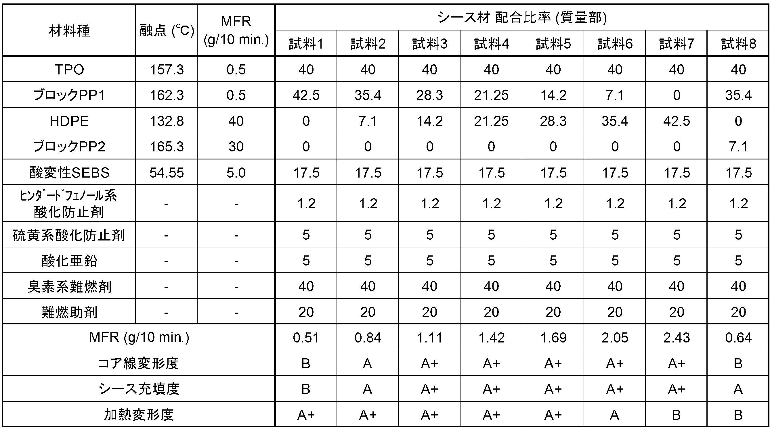
試料1~7では、ブロックPP1とHDPEの含有割合を系統的に変化させている。試料1から試料7へと、HDPEの含有割合を増やしている。ここで、HDPEは、140℃以下の融点と、15g/10分以上のMFRを有しており、低融点ポリマーに分類される。一方、ブロックPP1は、160℃以上の融点を有しており、高融点ポリマーに分類される。
試料1~7において、HDPEの含有割合を増加させるほど、組成物全体としてのMFRが上昇している。MFRが0.8g/10分以上となっている試料2~7では、コア線変形度が小さく抑えられるとともに、シース充填度が高くなっている(ともにAまたはA+)。中でも、組成物のMFRが1.0g/10分以上となっている試料3~7では、コア線変形度が特に小さく抑えられるとともに、シース充填度も特に高くなっている(ともにA+)。この結果は、MFRの高い組成物でシースを構成することで、シース形成時の熱および樹脂圧の影響による絶縁電線の相対位置の変化および変形を抑制でき、またシースを構成する組成物を密に充填できることを示している。
一方、組成物全体としてのMFRが2.1g/10分以下となっている試料1~6では、通信用電線の加熱変形度が、小さく抑えられている(AまたはA+)。特に、MFRが2.0g/10分以下となっている試料1~5では、加熱変形度が特に小さく抑えられている(A+)。この結果は、シース材料のMFRを高くなりすぎないように抑えておくことで、通信用電線において、加熱環境下でのシースの変形を小さく抑えられることを示している。
試料8では、試料1~7と異なり、低融点ポリマーであるHDPEを添加する代わりに、高いMFRを有するものの、融点が160℃以上であり、高融点ポリマーに分類されるブロックPP2を添加している。ブロックPP2の添加量は、試料2におけるHDPEと同じになっているが、組成物全体としてのMFRが、試料8の方で低くなっており、0.8g/10分を下回っている。そして試料8では、シース材全体としてのMFRの低さに対応して、コア線変形度が高くなってしまっている。また、ブロックPP2が、高いMFRを有する成分であることに対応して、加熱変形度も高くなってしまっている。
以上のように、シースを構成する材料のMFRを0.8g/10分以上、2.1g/10分以下の範囲とすることで、通信用電線において、シース形成時の絶縁電線の相対位置のずれおよび変形を抑制した状態で、それら絶縁電線の外周に密にシースの構成材料を充填することができる。同時に、製造された通信用電線において、シースの加熱変形を抑制することができる。上記の範囲のMFRは、高融点ポリマーと低融点ポリマーを混合することで、達成しやすい。なお、上記では、低融点ポリマーとして、HDPEを用いているが、HDPEの代わりに、LDPE(融点106.4℃、MFR15g/10分)を低融点ポリマーとして用いた場合にも、結果の掲載は省略するが、同様の結果が得られた。
以上、本開示の実施の形態について詳細に説明したが、本発明は上記実施の形態に何ら限定されるものではなく、本発明の要旨を逸脱しない範囲で種々の改変が可能である。
1,1A~1C 通信用電線
10 信号線
11 絶縁電線
12 導体
13 絶縁被覆
20 シース
A0 電線間領域
A1 充填領域
A2 荷重印加領域
D1 絶縁電線の長径
D2 絶縁電線の短径
D3 加熱変形試験前の電線外径
D4 加熱変形試験後の電線外径
10 信号線
11 絶縁電線
12 導体
13 絶縁被覆
20 シース
A0 電線間領域
A1 充填領域
A2 荷重印加領域
D1 絶縁電線の長径
D2 絶縁電線の短径
D3 加熱変形試験前の電線外径
D4 加熱変形試験後の電線外径
Claims (7)
- 導体と、前記導体の外周を被覆する絶縁被覆と、を有する絶縁電線を複数含む信号線と、
前記信号線の外周を被覆する充実状のシースと、を有し、
前記シースを構成する組成物は、230℃において荷重2.16kgで計測されるメルトフローレートが、0.8g/10分以上、2.1g/10分以下である、通信用電線。 - 前記信号線は、1対の前記絶縁電線が相互に撚り合わせられた対撚線として構成されている、請求項1に記載の通信用電線。
- 前記シースと前記信号線の間には、他の部材が設けられない、請求項1または請求項2に記載の通信用電線。
- 前記シースは、230℃において荷重2.16kgで計測されるメルトフローレートが15g/10分以上であり、融点が140℃以上である、低融点ポリマーを含んでいる、請求項1から請求項3のいずれか1項に記載の通信用電線。
- 前記シースを構成するポリマー成分の中で、前記低融点ポリマーが占める割合が、前記絶縁被覆を構成するポリマー成分の中で、前記低融点ポリマーが占める割合よりも大きい、請求項4に記載の通信用電線。
- 前記シースは、融点160℃以上である高融点ポリマーをさらに含む、請求項4または請求項5に記載の通信用電線。
- 前記低融点ポリマーおよび前記高融点ポリマーは、いずれもポリオレフィンを含む、請求項6に記載の通信用電線。
Applications Claiming Priority (2)
| Application Number | Priority Date | Filing Date | Title |
|---|---|---|---|
| JP2021049770A JP2022148187A (ja) | 2021-03-24 | 2021-03-24 | 通信用電線 |
| JP2021-049770 | 2021-03-24 |
Publications (1)
| Publication Number | Publication Date |
|---|---|
| WO2022202174A1 true WO2022202174A1 (ja) | 2022-09-29 |
Family
ID=83396916
Family Applications (1)
| Application Number | Title | Priority Date | Filing Date |
|---|---|---|---|
| PCT/JP2022/009045 Ceased WO2022202174A1 (ja) | 2021-03-24 | 2022-03-03 | 通信用電線 |
Country Status (2)
| Country | Link |
|---|---|
| JP (1) | JP2022148187A (ja) |
| WO (1) | WO2022202174A1 (ja) |
Families Citing this family (1)
| Publication number | Priority date | Publication date | Assignee | Title |
|---|---|---|---|---|
| JP7808253B2 (ja) * | 2024-01-17 | 2026-01-29 | 古河電工メタルケーブル株式会社 | サイロ測温ケーブル |
Citations (4)
| Publication number | Priority date | Publication date | Assignee | Title |
|---|---|---|---|---|
| JPS58224727A (ja) * | 1982-06-24 | 1983-12-27 | Sumitomo Electric Ind Ltd | 発泡体の製造方法 |
| JP2005538528A (ja) * | 2002-09-10 | 2005-12-15 | ユニオン・カーバイド・ケミカルズ・アンド・プラスティックス・テクノロジー・コーポレイション | 溶融強度および物理特性が強化されたポリプロピレンケーブル被覆組成物 |
| JP2011221252A (ja) * | 2010-04-08 | 2011-11-04 | Fujikura Ltd | 光ファイバケーブル及び光ファイバケーブルの製造方法 |
| WO2017168842A1 (ja) * | 2016-03-31 | 2017-10-05 | 株式会社オートネットワーク技術研究所 | 通信用電線 |
-
2021
- 2021-03-24 JP JP2021049770A patent/JP2022148187A/ja active Pending
-
2022
- 2022-03-03 WO PCT/JP2022/009045 patent/WO2022202174A1/ja not_active Ceased
Patent Citations (4)
| Publication number | Priority date | Publication date | Assignee | Title |
|---|---|---|---|---|
| JPS58224727A (ja) * | 1982-06-24 | 1983-12-27 | Sumitomo Electric Ind Ltd | 発泡体の製造方法 |
| JP2005538528A (ja) * | 2002-09-10 | 2005-12-15 | ユニオン・カーバイド・ケミカルズ・アンド・プラスティックス・テクノロジー・コーポレイション | 溶融強度および物理特性が強化されたポリプロピレンケーブル被覆組成物 |
| JP2011221252A (ja) * | 2010-04-08 | 2011-11-04 | Fujikura Ltd | 光ファイバケーブル及び光ファイバケーブルの製造方法 |
| WO2017168842A1 (ja) * | 2016-03-31 | 2017-10-05 | 株式会社オートネットワーク技術研究所 | 通信用電線 |
Also Published As
| Publication number | Publication date |
|---|---|
| JP2022148187A (ja) | 2022-10-06 |
Similar Documents
| Publication | Publication Date | Title |
|---|---|---|
| JP5842780B2 (ja) | 発泡樹脂組成物、電線、及びケーブル | |
| KR101968388B1 (ko) | 전력 케이블 | |
| JP4916590B1 (ja) | 伝送ケーブル用絶縁電線及び伝送ケーブル | |
| JP7259848B2 (ja) | 絶縁層用樹脂組成物、絶縁電線及びケーブル | |
| JP6113823B2 (ja) | GHz帯域の周波数の信号を伝送する絶縁電線用絶縁樹脂組成物、絶縁電線及びケーブル | |
| EP3745427A1 (en) | Power cable | |
| WO2022202174A1 (ja) | 通信用電線 | |
| US20080296041A1 (en) | Insulated wire, insulated cable, non-halogen flame retardant wire, and non-halogen flame retardant cable | |
| WO2024171366A1 (ja) | 通信ケーブル及びそれを用いたワイヤーハーネス | |
| WO2021015121A1 (ja) | 絶縁層用樹脂組成物、絶縁電線及びケーブル | |
| JP5687024B2 (ja) | 絶縁電線用絶縁樹脂組成物、絶縁電線及びケーブル | |
| JP7396114B2 (ja) | 通信用電線 | |
| WO2023127622A1 (ja) | 通信用電線 | |
| KR20200058334A (ko) | 비가교 수지로 이루어진 전력 케이블의 절연층 제조용 혼합물 | |
| EP3819918A1 (en) | Power cable | |
| US20240150554A1 (en) | Communication cable, wire harness, and method for manufacturing communication cable | |
| JP7384271B2 (ja) | 通信用電線およびワイヤーハーネス | |
| WO2023228500A1 (ja) | 絶縁電線及び情報伝送用ケーブル | |
| JP4951704B1 (ja) | 伝送ケーブル用絶縁電線及び伝送ケーブル | |
| EP3859752A1 (en) | Insulator and power cable comprising same | |
| KR20220168284A (ko) | 반도전성 조성물 및 이로부터 형성된 반도전층을 갖는 전력 케이블 | |
| JP7568821B2 (ja) | 通信ケーブル及びそれを用いたワイヤーハーネス | |
| JP7796182B1 (ja) | 樹脂組成物、樹脂組成物を用いた絶縁電線、通信ケーブル及び絶縁電線の製造方法 | |
| JP5926827B2 (ja) | 絶縁電線用絶縁樹脂組成物、絶縁電線及びケーブル | |
| TW202605056A (zh) | 樹脂組成物、使用了樹脂組成物的絕緣電線、通信電纜、絕緣電線的製造方法、及樹脂組成物的使用 |
Legal Events
| Date | Code | Title | Description |
|---|---|---|---|
| 121 | Ep: the epo has been informed by wipo that ep was designated in this application |
Ref document number: 22774970 Country of ref document: EP Kind code of ref document: A1 |
|
| NENP | Non-entry into the national phase |
Ref country code: DE |
|
| 122 | Ep: pct application non-entry in european phase |
Ref document number: 22774970 Country of ref document: EP Kind code of ref document: A1 |