WO2022201959A1 - 生体粒子分取装置及び生体粒子分取装置における分取条件調整方法 - Google Patents
生体粒子分取装置及び生体粒子分取装置における分取条件調整方法 Download PDFInfo
- Publication number
- WO2022201959A1 WO2022201959A1 PCT/JP2022/005606 JP2022005606W WO2022201959A1 WO 2022201959 A1 WO2022201959 A1 WO 2022201959A1 JP 2022005606 W JP2022005606 W JP 2022005606W WO 2022201959 A1 WO2022201959 A1 WO 2022201959A1
- Authority
- WO
- WIPO (PCT)
- Prior art keywords
- time
- particles
- biological particle
- sorting device
- fractionation
- Prior art date
- Legal status (The legal status is an assumption and is not a legal conclusion. Google has not performed a legal analysis and makes no representation as to the accuracy of the status listed.)
- Ceased
Links
Images








Classifications
-
- G—PHYSICS
- G01—MEASURING; TESTING
- G01N—INVESTIGATING OR ANALYSING MATERIALS BY DETERMINING THEIR CHEMICAL OR PHYSICAL PROPERTIES
- G01N15/00—Investigating characteristics of particles; Investigating permeability, pore-volume or surface-area of porous materials
- G01N15/10—Investigating individual particles
- G01N15/14—Optical investigation techniques, e.g. flow cytometry
- G01N15/149—Optical investigation techniques, e.g. flow cytometry specially adapted for sorting particles, e.g. by their size or optical properties
-
- B—PERFORMING OPERATIONS; TRANSPORTING
- B01—PHYSICAL OR CHEMICAL PROCESSES OR APPARATUS IN GENERAL
- B01L—CHEMICAL OR PHYSICAL LABORATORY APPARATUS FOR GENERAL USE
- B01L3/00—Containers or dishes for laboratory use, e.g. laboratory glassware; Droppers
- B01L3/50—Containers for the purpose of retaining a material to be analysed, e.g. test tubes
- B01L3/502—Containers for the purpose of retaining a material to be analysed, e.g. test tubes with fluid transport, e.g. in multi-compartment structures
- B01L3/5027—Containers for the purpose of retaining a material to be analysed, e.g. test tubes with fluid transport, e.g. in multi-compartment structures by integrated microfluidic structures, i.e. dimensions of channels and chambers are such that surface tension forces are important, e.g. lab-on-a-chip
- B01L3/502761—Containers for the purpose of retaining a material to be analysed, e.g. test tubes with fluid transport, e.g. in multi-compartment structures by integrated microfluidic structures, i.e. dimensions of channels and chambers are such that surface tension forces are important, e.g. lab-on-a-chip specially adapted for handling suspended solids or molecules independently from the bulk fluid flow, e.g. for trapping or sorting beads or physically stretching molecules
-
- G—PHYSICS
- G01—MEASURING; TESTING
- G01N—INVESTIGATING OR ANALYSING MATERIALS BY DETERMINING THEIR CHEMICAL OR PHYSICAL PROPERTIES
- G01N15/00—Investigating characteristics of particles; Investigating permeability, pore-volume or surface-area of porous materials
- G01N15/02—Investigating particle size or size distribution
-
- G—PHYSICS
- G01—MEASURING; TESTING
- G01N—INVESTIGATING OR ANALYSING MATERIALS BY DETERMINING THEIR CHEMICAL OR PHYSICAL PROPERTIES
- G01N15/00—Investigating characteristics of particles; Investigating permeability, pore-volume or surface-area of porous materials
- G01N15/10—Investigating individual particles
- G01N15/14—Optical investigation techniques, e.g. flow cytometry
- G01N15/1425—Optical investigation techniques, e.g. flow cytometry using an analyser being characterised by its control arrangement
-
- G—PHYSICS
- G01—MEASURING; TESTING
- G01N—INVESTIGATING OR ANALYSING MATERIALS BY DETERMINING THEIR CHEMICAL OR PHYSICAL PROPERTIES
- G01N15/00—Investigating characteristics of particles; Investigating permeability, pore-volume or surface-area of porous materials
- G01N15/10—Investigating individual particles
- G01N15/14—Optical investigation techniques, e.g. flow cytometry
- G01N15/1456—Optical investigation techniques, e.g. flow cytometry without spatial resolution of the texture or inner structure of the particle, e.g. processing of pulse signals
- G01N15/1459—Optical investigation techniques, e.g. flow cytometry without spatial resolution of the texture or inner structure of the particle, e.g. processing of pulse signals the analysis being performed on a sample stream
-
- G—PHYSICS
- G01—MEASURING; TESTING
- G01N—INVESTIGATING OR ANALYSING MATERIALS BY DETERMINING THEIR CHEMICAL OR PHYSICAL PROPERTIES
- G01N15/00—Investigating characteristics of particles; Investigating permeability, pore-volume or surface-area of porous materials
- G01N15/10—Investigating individual particles
- G01N15/14—Optical investigation techniques, e.g. flow cytometry
- G01N15/1484—Optical investigation techniques, e.g. flow cytometry microstructural devices
-
- B—PERFORMING OPERATIONS; TRANSPORTING
- B01—PHYSICAL OR CHEMICAL PROCESSES OR APPARATUS IN GENERAL
- B01L—CHEMICAL OR PHYSICAL LABORATORY APPARATUS FOR GENERAL USE
- B01L2200/00—Solutions for specific problems relating to chemical or physical laboratory apparatus
- B01L2200/06—Fluid handling related problems
- B01L2200/0647—Handling flowable solids, e.g. microscopic beads, cells, particles
- B01L2200/0652—Sorting or classification of particles or molecules
-
- B—PERFORMING OPERATIONS; TRANSPORTING
- B01—PHYSICAL OR CHEMICAL PROCESSES OR APPARATUS IN GENERAL
- B01L—CHEMICAL OR PHYSICAL LABORATORY APPARATUS FOR GENERAL USE
- B01L2200/00—Solutions for specific problems relating to chemical or physical laboratory apparatus
- B01L2200/14—Process control and prevention of errors
- B01L2200/143—Quality control, feedback systems
-
- B—PERFORMING OPERATIONS; TRANSPORTING
- B01—PHYSICAL OR CHEMICAL PROCESSES OR APPARATUS IN GENERAL
- B01L—CHEMICAL OR PHYSICAL LABORATORY APPARATUS FOR GENERAL USE
- B01L2300/00—Additional constructional details
- B01L2300/08—Geometry, shape and general structure
- B01L2300/0809—Geometry, shape and general structure rectangular shaped
- B01L2300/0816—Cards, e.g. flat sample carriers usually with flow in two horizontal directions
-
- B—PERFORMING OPERATIONS; TRANSPORTING
- B01—PHYSICAL OR CHEMICAL PROCESSES OR APPARATUS IN GENERAL
- B01L—CHEMICAL OR PHYSICAL LABORATORY APPARATUS FOR GENERAL USE
- B01L2300/00—Additional constructional details
- B01L2300/08—Geometry, shape and general structure
- B01L2300/0861—Configuration of multiple channels and/or chambers in a single devices
- B01L2300/0864—Configuration of multiple channels and/or chambers in a single devices comprising only one inlet and multiple receiving wells, e.g. for separation, splitting
-
- B—PERFORMING OPERATIONS; TRANSPORTING
- B01—PHYSICAL OR CHEMICAL PROCESSES OR APPARATUS IN GENERAL
- B01L—CHEMICAL OR PHYSICAL LABORATORY APPARATUS FOR GENERAL USE
- B01L2400/00—Moving or stopping fluids
- B01L2400/04—Moving fluids with specific forces or mechanical means
- B01L2400/0475—Moving fluids with specific forces or mechanical means specific mechanical means and fluid pressure
- B01L2400/0481—Moving fluids with specific forces or mechanical means specific mechanical means and fluid pressure squeezing of channels or chambers
-
- G—PHYSICS
- G01—MEASURING; TESTING
- G01N—INVESTIGATING OR ANALYSING MATERIALS BY DETERMINING THEIR CHEMICAL OR PHYSICAL PROPERTIES
- G01N15/00—Investigating characteristics of particles; Investigating permeability, pore-volume or surface-area of porous materials
- G01N15/02—Investigating particle size or size distribution
- G01N2015/0288—Sorting the particles
Definitions
- the present disclosure relates to a bioparticle sorting device and a method for adjusting the sorting conditions in the bioparticle sorting device.
- bioparticle fractionation devices have been developed so far to fractionate bioparticles.
- a laminar flow composed of a sample liquid containing cells and a sheath liquid is discharged from an orifice formed in a flow cell or microchip.
- a predetermined vibration is applied to the laminar flow when it is discharged to form droplets.
- the movement direction of the formed droplet is electrically controlled depending on whether or not the target particles are included, and the target particles are fractionated.
- Patent Document 1 a sample liquid introduction channel through which a sample liquid containing microparticles flows, and a sheath liquid that merges from both sides of the sample liquid introduction channel to introduce a sheath liquid around the sample liquid.
- the present inventors found that the occurrence of cavitation can be prevented by adjusting the driving waveform of the element based on specific information.
- the present disclosure a pressure change element that changes the pressure in the channel in which the bioparticles determined to be sorted are recovered; a control unit that drives the pressure change element; and The control unit Information on the number of preparative runs per unit time, or adjusting the driving waveform of the pressure change element based on information on the ratio or number of particles to be sorted contained in the unit sample;
- a biological particle sorting device is provided.
- the controller can adjust the driving time, the driving voltage, or both the driving time and the driving voltage among the elements of the driving waveform.
- the control unit may lengthen the drive time, lower the drive voltage, or both, when the number of preparative collection processes is equal to or greater than a predetermined value.
- the number of fractionation processes may be a counted number of fractionation processes or an estimated number of fractionation processes.
- the number of fractionation processes may be the number of times the pressure change element is driven per unit time.
- the number of fractionation processes may be the number of times per unit time that fractionation is determined.
- the biological particle sorting device further comprises a determination unit that determines whether to sort the biological particles,
- the control unit may adjust the drive waveform based on information about the number of times the determination unit has determined that fractionation should be performed.
- the control unit may lengthen the drive time, lower the drive voltage, or both, when the ratio or number of the particles to be sorted is equal to or greater than a predetermined value.
- the information on the ratio or number of particles to be sorted may be information obtained as a result of the sorting operation performed by the biological particle sorting device or information input to the biological particle sorting device.
- the control section may adjust one or more of a boost time, a voltage drop time, and a hold time among the elements of the drive waveform.
- the control unit selects, from among a plurality of preset drive waveforms, based on either the information on the number of times of fractionation processing and the information on the ratio or number of particles to be fractionated, The applied drive waveform can be selected.
- the control unit may adjust the driving waveform in a preparative collection condition parameter adjustment step before performing a biological sample preparative processing step or in the biological sample preparative processing step.
- the control unit controls information on the number of fractionation processes per unit time or information on the ratio or number of particles to be fractionated contained in the unit sample, and a drive voltage set for application to the fractionation process.
- the driving time can be adjusted based on
- the control unit is configured to adjust the drive waveform in a preparative separation condition parameter adjustment step prior to a biological sample preparative treatment step, and The control unit can adjust the drive time in the fractionation condition parameter adjustment step.
- the control unit can adjust the drive waveform during the fractionation operation.
- the control unit can adjust the drive waveform in response to a change in the particles to be sorted during the sorting operation.
- the biological particle sorting device may be configured to execute a parameter adjusting step of adjusting sorting condition parameters used in the biological sample sorting process.
- the biological particle sorting device may be configured to execute delay time adjustment processing in the parameter adjustment step.
- the biological particle sorting device may be configured to measure the yield represented by the number of sorted particles with respect to the number of sorting operations in the delay time adjustment process. Only when there are no other bioparticles within a predetermined range around the bioparticle determined to be sorted in the yield measurement, the bioparticle may be subjected to the sorting operation.
- This disclosure also provides including a drive waveform adjustment step of adjusting the drive waveform of the pressure change element that changes the pressure in the channel in which the bioparticles determined to be sorted are collected,
- a drive waveform adjustment step Information on the number of preparative runs per unit time, or adjusting the driving waveform of the pressure change element based on information on the ratio or number of particles to be sorted contained in the unit sample;
- a method for adjusting collection conditions in a biological particle collection device is also provided.
- FIG. 1 is a diagram showing a configuration example of a bioparticle sorting device according to the present disclosure and a bioparticle sorting microchip included in the device;
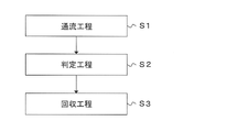
- FIG. 4 is a diagram showing an example of the flow of bioparticle sorting processing performed using the bioparticle sorting device according to the present disclosure;
- FIG. 2 is an enlarged view of an example of a particle sorting section of a bioparticle sorting microchip used in the present disclosure;
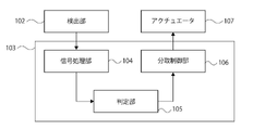
- 4 is a block diagram of an example of a control unit;
- FIG. FIG. 4 is a schematic enlarged view of an example of a connecting channel portion;
- FIG. 4 is a schematic enlarged view of an example of a connecting channel portion;
- FIG. 1 is a diagram showing a configuration example of a bioparticle sorting device according to the present disclosure and a bioparticle sorting microchip included in the device;
- FIG. 4 is a diagram showing an example of the flow of bioparticle sorting processing performed using the bioparticle sorting device according to the
- FIG. 4 is a schematic enlarged view of an example of a connecting channel portion;
- FIG. 4 is a schematic enlarged view of an example of a connecting channel portion;
- FIG. 4 is a diagram schematically showing a state in which the pressure change element is in contact with the bioparticle sorting microchip.
- FIG. 2 is a schematic diagram of a biological particle sorting microchip for explaining the delay time;
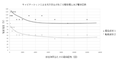
- FIG. 5 is a diagram showing examples of drive waveforms and the relationship between the drive waveforms and changes in the flow path; 7 is a graph for explaining the relationship between the number of times of driving and the occurrence of cavitation;
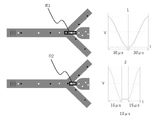
- FIG. 4 is a diagram for explaining an example of drive waveforms;
- FIG. 5 is a diagram for explaining the relationship between drive time and the amount of suction to the particle fractionation channel;
- FIG. 4 is a diagram showing an example of an operation flow in the biological particle sorting device of the present disclosure; It is a figure which shows an example of the flow of a parameter adjustment process.
- FIG. 5 is a diagram showing an example of the relationship between delay time and yield;
- FIG. 4 is a schematic diagram showing a state in which biological particles are aligned in a line and flow in a traveling direction D in a channel.
- FIG. 3 is a schematic diagram showing a state in which a plurality of sorting target particles are sorted.
- FIG. 3 is a schematic diagram showing a state in which a plurality of sorting target particles are sorted. It is an example of a flow chart of a delay time setting process.
- Biological particle sorting device (1) Description of the first embodiment (2) Example of biological particle sorting device (2-1) Configuration of device and sorting operation (2-2) Flow process (2-3) Judgment process (2-) 4) Collection process (2-5) Bioparticle fractionation microchip and bioparticles (3) Adjustment of drive waveform (3-1) Explanation of drive waveform adjustment for cavitation generation and prevention thereof (3-1-1 ) Occurrence of cavitation accompanying improvement in fractionation efficiency (3-1-2) Usefulness of driving waveform adjustment in setting parameters for fractionation conditions (3-1-3) Relationship between number of times of driving and generation of cavitation (3-1- 4) Relationship between driving time and amount of suction to particle fractionation channel (3-1-5) Basic concept of the present disclosure (3-2) Adjustment of driving waveform based on information on number of fractionation processes (3- 3) Adjustment of drive waveform based on information on the ratio or number of particles to be sorted (3-4) Timing of drive waveform adjustment (3-4-1) Drive waveform adjustment in fractionation condition parameter adjustment step (3-4).
- a bioparticle sorting apparatus includes a pressure change element that changes the pressure in a flow channel in which bioparticles determined to be sorted are collected, and a control unit that drives the pressure change element.
- the control unit is configured to adjust the driving waveform of the pressure change element based on information about the number of fractionation processes per unit time or information about the ratio or number of particles to be fractionated contained in the unit sample. .
- the bioparticle sorting device may be configured as a device for sorting bioparticles in a closed space, for example, as a device for sorting bioparticles by controlling the flow path in which the bioparticles advance. may be configured.
- FIG. 1 shows a configuration example of a biological particle sorting device according to the present disclosure. The figure also shows an example of the channel structure of a bioparticle fractionation microchip (hereinafter also referred to as "microchip") attached to the device.
- FIG. 2 shows an example of a flow chart of the sorting process executed by the biological particle sorting device.
- the bioparticle sorting device 100 further includes a microchip 150 .
- Microchip 150 may be replaceably attached to bioparticle sorting device 150 .
- the control unit 103 can include a signal processing unit 104, a determination unit 105, and a fractionation control unit 106, as shown in FIG.
- the bioparticle sorting microchip 150 will be first described below, and then, while the sorting operation by the biological particle sorting device 100 will be described, other components of the device will be described.
- the biological particle sorting microchip 150 shown in FIG. 1 has a sample liquid channel 152 and a sheath liquid channel 154 that joins the sample liquid channel 152 at a junction 162 .
- the biological particle sorting microchip 150 is further provided with a sample fluid inlet 151 and a sheath fluid inlet 153 .
- a portion of the sheath liquid flow path 154 is indicated by a dotted line.
- the portion indicated by the dotted line is located lower than the sample liquid flow path 152 indicated by the solid line (position shifted in the optical axis direction as indicated by the arrow extending from reference numeral 101 to 102). At the intersection of the flow path indicated by the solid line and the flow path indicated by the solid line, these flow paths do not communicate.
- the sample liquid flow path 152 is shown to bend twice between the sample liquid inlet 151 and the confluence portion 162. This is for facilitating the distinction between The sample liquid flow path 152 may be configured linearly from the sample liquid inlet 151 to the confluence section 162 without such a bend.
- a sample liquid containing bioparticles is introduced from the sample liquid inlet 151 into the sample liquid channel 152, and a sheath liquid containing no bioparticles is introduced from the sheath liquid inlet 153 into the sheath liquid channel 154. be done.
- the biological particle sorting microchip 150 has a confluence channel 155 having a confluence portion 162 at one end.
- the confluence channel 155 includes a fractionation discrimination section 156 used for fractionation discrimination of bioparticles.
- the sample liquid and the sheath liquid merge at the confluence section 162 and flow through the confluence channel 155 toward the particle sorting section 157 .
- the sample liquid and the sheath liquid merge at the confluence portion 162 to form, for example, a laminar flow in which the sample liquid is surrounded by the sheath liquid.
- the biological particles are aligned substantially in a line in the laminar flow.
- a laminar flow is formed containing the bioparticles.
- the biological particle sorting microchip 150 further has a particle sorting section 157 at the other end of the confluence channel 155 .
- FIG. 3 shows an enlarged view of the particle sorting section 157.
- the confluence channel 155 is connected to the biological particle recovery channel 159 via a connection channel 170, as shown in FIG. 3A.
- the confluence channel 155, the connecting channel 170, and the bioparticle recovery channel 159 may be coaxial.
- a flow entering the bioparticle recovery channel 159 is formed, and the particles to be recovered are recovered into the bioparticle recovery channel 159 .
- the particles to be collected flow through the connection channel 170 to the biological particle recovery channel 159 .
- the biological particles that are not to be collected flow into the particle sorting section 157, the biological particles that are not to be collected flow into the branch channel 158 as shown in FIG. 3C. In this case, no flow entering the biological particle collection channel 159 is formed.
- the biological particle recovery channel 159 extends linearly from the particle sorting section 157, makes a U-turn, and reaches the same plane as the plane formed by the sample liquid inlet 151 and the sheath liquid inlet 153. is formed to The liquid flowing through the biological particle recovery channel 159 is discharged from the recovery channel end 163 to the outside of the chip.
- the two branch channels 158 also extend linearly from the particle sorting section 157, make a U-turn, and extend on the same plane as the sample liquid inlet 151 and the sheath liquid inlet 153 are formed. is designed to reach Liquid flowing through the branch channel 158 is discharged from the branch channel end 160 to the outside of the chip.
- the biological particle recovery channel 159 is changed from a solid line to a dotted line at the U-turn portion. This change indicates that the position in the direction of the optical axis changes during the change. By changing the position in the optical axis direction in this way, the biological particle recovery channel 159 and the branched channel 158 are not communicated with each other at the intersection with the branched channel 158 .
- Both the collection channel end 163 and the two branch channel ends 166 are formed on the surface where the sample fluid inlet 151 and the sheath fluid inlet 153 are formed.
- an introduction channel inlet 164 for introducing liquid into an introduction channel 161, which will be described later, is also formed on the surface.
- the biological particle sorting microchip 150 has an inlet into which liquid is introduced and an outlet from which liquid is discharged, all of which are formed on one surface. This facilitates attachment of the chip to the biological particle sorting device 100 . For example, compared to the case where inlets and/or outlets are formed on two or more surfaces, the connection between the channel provided in the biological particle sorting device 100 and the channel of the biological particle sorting microchip 150 becomes easier.
- the biological particle sorting microchip 150 has an introduction channel 161 for introducing a liquid to the connection channel 170, as shown in FIGS. By introducing the liquid from the introduction channel 161 into the connection channel 170, the inside of the connection channel 170 is filled with the liquid. This can prevent unintended biological particles from entering the biological particle recovery channel 159 .
- the bioparticle sorting microchip 150 has two branch channels 158 connected to the confluence channel 155 at the other end of the confluence channel 155 .
- the confluence channel may branch into the connection channel and the at least one branch channel. Bioparticles other than the particles to be collected flow into either of the two branch channels 158 without entering the bioparticle recovery channel 159 .
- the bioparticle sorting operation using the bioparticle sorting microchip 150 consists of a flow step S1 in which the liquid containing the bioparticles flows into the confluence channel 155, and a flow step S1 of the bioparticles flowing through the confluence channel 155. It includes a determination step S2 of determining whether the particles are collection target particles and a collection step S3 of collecting the collection target particles into the bioparticle collection channel 159 . Each step will be described below.
- the sample liquid containing bioparticles and the sheath liquid not containing bioparticles are introduced from the sample liquid inlet 151 and the sheath liquid inlet 153 into the sample liquid flow path 152 and the sheath liquid flow path 154, respectively.
- the sample liquid may be, for example, a biological sample containing biological particles, in particular a biological sample containing biological particles such as cells.
- the biological particles are aligned substantially in a line in the laminar flow. That is, in the flow-through step S1, a laminar flow containing bioparticles flowing substantially in a line can be formed.
- the liquid containing bioparticles is flowed through the confluence channel 155, particularly as a laminar flow.
- the liquid flows through the confluence channel 155 from the confluence portion 162 toward the particle sorting portion 157 .
- the determination step S2 it is determined whether the biological particles flowing through the confluence channel 155 are particles to be collected.
- the determination can be made by the determination unit 105 .
- the determination unit 105 can make the determination based on the light generated by the light irradiation of the biological particles by the light irradiation unit 101 .
- An example of the determination step S2 is described in more detail below.
- the light irradiation unit 101 irradiates the bioparticles flowing through the confluence channel 155 (particularly, the fractionation determination unit 156) in the bioparticle fractionation microchip 150 with light (for example, excitation light).
- the detection unit 102 detects the light generated by the light irradiation.
- the determination unit 105 determines whether the biological particles are particles to be collected. For example, the determination unit 105 can perform determination based on scattered light, determination based on fluorescence, or determination based on an image (for example, a dark field image and/or a bright field image).
- the particles to be recovered are recovered into the bioparticle recovery channel 159 by controlling the flow in the bioparticle sorting microchip 150 by the control unit 103 .
- the light irradiator 101 irradiates the bioparticles flowing in the channel in the microchip 150 for sorting bioparticles with light (excitation light, for example).
- the light irradiation unit 101 can include a light source that emits light and an objective lens that collects the excitation light on the biological particles flowing through the fractionation determination unit.
- the light source may be appropriately selected by those skilled in the art depending on the purpose of analysis, and may be, for example, a laser diode, an SHG laser, a solid state laser, a gas laser, a high brightness LED, or a halogen lamp, or two of these. A combination of the above may also be used.
- the light irradiation section may contain other optical elements as necessary.
- the detection unit 102 detects scattered light and/or fluorescence generated from the bioparticles by light irradiation by the light irradiation unit 101 .
- the detection unit 102 may include a condenser lens and a detector that collect fluorescence and/or scattered light generated from biological particles.
- a PMT, a photodiode, a CCD, a CMOS, and the like can be used as the detector, but are not limited to these.
- the detection unit 102 may include other optical elements as needed in addition to the condenser lens and detector.
- the detection unit 102 can further include, for example, a spectroscopic unit.
- the spectroscopic section can detect light of a wavelength to be detected separately from light of other wavelengths.
- the detection unit 102 can convert the detected light into an analog electric signal by photoelectric conversion.
- the detection unit 102 can further convert the analog electric signal into a digital electric signal by AD conversion.
- the detection unit 102 may acquire an image generated by light irradiation by the light irradiation unit 101.
- the images may be, for example, dark field images, bright field images, or both.
- the light irradiation section 101 may include, for example, a halogen lamp or laser, and the detection section 102 may include a CCD or CMOS.
- the detection unit 102 may be, for example, an imaging device in which a substrate in which a CMOS sensor is incorporated and a substrate in which a DSP (Digital Signal Processor) is incorporated are laminated.
- DSP Digital Signal Processor
- the detection unit 102 including the imaging device can determine whether the biological particles are particles to be collected based on, for example, a learning model. Also, the learning model may be updated in real time while the method according to the present disclosure is being performed. For example, a DSP can perform machine learning processing while resetting a pixel array section in a CMOS sensor, exposing the pixel array section, or reading pixel signals from each unit pixel of the pixel array section.
- a DSP can perform machine learning processing while resetting a pixel array section in a CMOS sensor, exposing the pixel array section, or reading pixel signals from each unit pixel of the pixel array section.
- An example of an imaging device that operates as an AI sensor is the imaging device described in International Publication No. 2018/051809.
- a signal processing unit 104 included in the control unit 103 processes the waveform of the digital electric signal obtained by the detection unit 102 to generate information (data) regarding the characteristics of light used for determination by the determination unit 105. sell.
- the signal processing unit 104 extracts one, two, or three of the width of the waveform, the height of the waveform, and the area of the waveform from the waveform of the digital electrical signal. can be obtained.
- the information about the characteristics of the light may include, for example, the time when the light was detected.
- the processing by the signal processing unit 104 described above can be performed particularly in an embodiment in which the scattered light and/or fluorescence are detected.
- a determination unit 105 included in the control unit 103 determines whether the biological particles flowing in the flow path are particles to be collected, based on the light generated by irradiating the biological particles flowing in the flow path.
- the waveform of the digital electrical signal obtained by the detector 102 is processed by the controller 103, and based on the information about the characteristics of the light generated by the processing, , the determining unit 105 determines whether the biological particles are particles to be collected. For example, in the determination based on scattered light, features of the external shape and/or internal structure of the bioparticle may be specified, and whether the bioparticle is the recovery target particle may be determined based on the feature.
- bioparticles such as cells
- bioparticles such as cells
- by labeling bioparticles such as cells with antibodies or dyes (especially fluorescent dyes) it is possible to determine whether the bioparticles are particles to be collected based on the characteristics of the surface antigens of the bioparticles.
- the determination unit 105 included in the control unit 103 determines that the biological particles are recovery target particles based on the acquired images (for example, dark field images, bright field images, or both). Determine if there is For example, based on one or a combination of two or more of the morphology, size, and color of the bioparticles (especially cells), it can be determined whether the bioparticles are particles to be collected.
- the determination can be made, for example, by whether the information about the characteristics of the light satisfies a pre-specified criterion.
- the criterion may be a criterion indicating that the biological particles are particles to be collected.
- the criteria may be appropriately set by those skilled in the art, and may be criteria relating to light characteristics, such as criteria used in technical fields such as flow cytometry.
- One position in the fractionation discrimination section 156 may be irradiated with one light, or each of a plurality of positions in the fractionation discrimination section 156 may be irradiated with light.
- the microchip 150 can be configured such that light is applied to each of two different positions in the preparative discrimination section 156 (i.e., there are two positions in the preparative discrimination section 156 that are illuminated with light). be.). In this case, for example, based on light (for example, fluorescence and/or scattered light) generated by irradiating the bioparticle at one position, it can be determined whether the bioparticle is a particle to be collected.
- the velocity of the biological particles in the flow channel calculates the velocity of the biological particles in the flow channel.
- the distance between the two irradiation positions may be determined in advance, and the velocity of the bioparticle can be determined based on the difference between the two detection times and the distance.
- the velocity it is possible to accurately predict the arrival time at the particle sorting section 157, which will be described below. By accurately predicting the arrival time, it is possible to optimize the timing of formation of the flow entering the biological particle recovery channel 159 (in particular, the timing of driving the pressure change element 107).
- a predetermined threshold value can also determine not to collect the certain bioparticle.
- the distance between the certain bioparticle and the preceding or succeeding bioparticle is small, the possibility that the preceding or succeeding bioparticle is collected together during the aspiration of the certain bioparticle increases. .
- the certain bioparticle is not to be recovered when the probability of being collected together is high, it is possible to prevent the bioparticle before or after the bioparticle from being recovered. As a result, the purity of the target bioparticles among the collected bioparticles can be increased.
- a specific example of a microchip that is irradiated with light at two different positions in the fractionation determination unit 156 and a device including the microchip is described in, for example, Japanese Patent Application Laid-Open No. 2014-202573.
- control unit 103 may control light irradiation by the light irradiation unit 101 and/or light detection by the detection unit 102 .
- control unit 103 can control driving of a pump for supplying fluid into the bioparticle fractionation microchip 150 .
- the control unit 103 may be composed of, for example, a hard disk storing a program and an OS for causing the biological particle sorting apparatus 100 to execute the biological particle sorting method according to the present disclosure, a CPU, and a memory.
- the functions of the control unit 103 can be implemented in a general-purpose computer.
- the program may be recorded in a recording medium such as a microSD memory card, an SD memory card, or a flash memory.
- a drive (not shown) provided in the biological particle sorting apparatus 100 reads the program recorded on the recording medium, and the control unit 103 performs biological particle separation according to the read program.
- the collection device 100 may be caused to perform the biological particle collection method according to the present disclosure.
- the bioparticles determined to be the particles to be recovered in the determination step S2 are recovered into the bioparticle recovery channel 159.
- the collection step S3 is performed in the particle sorting section 157 in the microchip 150 .
- the particle sorting section 157 the laminar flow that has flowed through the confluence channel 155 splits into two branch channels 158 .
- the particle sorting section 157 shown in FIG. 1 has two branch channels 158, the number of branch channels is not limited to two.
- the particle sorting section 157 may be provided with, for example, one or a plurality of (for example, two, three, four, etc.) branch channels.
- the branch channel may be configured to branch in a Y shape on one plane as in FIG. 1, or may be configured to branch three-dimensionally.
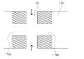
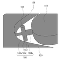
- FIGS. 5A and 5B Enlarged views of the vicinity of the connecting channel 170 are shown in FIGS. 5A and 5B.
- FIG. 5A is a schematic perspective view of the vicinity of the connecting channel 170.
- FIG. 5B is a schematic cross-sectional view of a plane passing through the center line of the introduction channel 161 and the center line of the connection channel 170.
- FIG. The connecting channel 170 includes a channel 170a (hereinafter also referred to as upstream connecting channel 170a) on the side of the fractionation determination unit 156 and a channel 170b (hereinafter referred to as downstream connecting channel 170b) on the biological particle recovery channel 159 side. ), and a connecting portion 170 c between the connection channel 170 and the introduction channel 161 .
- upstream connecting channel 170a on the side of the fractionation determination unit 156
- a channel 170b hereinafter referred to as downstream connecting channel 170b
- the introduction channel 161 is provided so as to be substantially perpendicular to the channel axis of the connection channel 170 .
- two introduction channels 161 are provided facing each other at substantially the center position of the connection channel 170, but only one introduction channel may be provided.
- the cross-sectional shape and dimensions of the upstream connection channel 170a may be the same as the shape and dimensions of the downstream connection channel 170b.
- both the cross-section of the upstream connecting channel 170a and the cross-section of the downstream connecting channel 170b may be substantially circular with the same dimensions.
- both of these two cross-sections may be rectangular (eg, square or rectangular, etc.) with the same dimensions.
- Liquid is supplied from the two introduction channels 161 to the connection channel 170 as indicated by the arrows in FIG. 5B.
- the liquid flows from the connecting portion 170c to both the upstream connecting channel 170a and the downstream connecting channel 170b.
- the liquid flows as follows.
- the liquid that has flowed to the upstream connection channel 170 a flows out of the connecting surface of the connection channel 170 to the confluence channel 155 and then flows separately into two branch channels 158 . Since the liquid is discharged from the connection surface in this way, the liquid and biological particles that do not need to be collected into the biological particle collection channel 159 pass through the connection channel 170 to the biological particle collection channel 159. can be prevented from entering.
- the liquid that has flowed to the downstream connection channel 170 b flows into the biological particle recovery channel 159 . As a result, the inside of the biological particle recovery channel 159 is filled with the liquid.
- the liquid can be supplied from the two introduction channels 161 to the connection channel 170 .
- the bioparticle recovery channel 159 passes from the confluence channel 155 through the connection channel 170 to the bioparticle recovery channel 159 .
- a stream is formed that flows to That is, a flow is formed that flows from the confluence channel 155 to the biological particle recovery channel 159 through the upstream connection channel 170a, the connection part 170c, and the downstream connection channel 170b in this order.
- the particles to be collected are collected in the bioparticle collection channel 159 .
- connection channel 180 includes a channel 180a on the side of the fractionation discrimination section 156 (hereinafter also referred to as an upstream connection channel 180a) and a channel 180b on the side of the biological particle recovery channel 159. (hereinafter also referred to as a downstream connection channel 180 b ), and a connecting portion 180 c between the connection channel 180 and the introduction channel 161 .
- Both the cross section of the upstream connection channel 180a and the cross section of the downstream connection channel 180b have a substantially circular shape, but the diameter of the latter cross section is larger than the diameter of the former cross section.
- the bioparticle collection channel 159 can receive more bioparticles immediately after the bioparticle sorting operation by the negative pressure described above. It is possible to more effectively prevent the particles to be collected that have already been fractionated from being released into the confluence channel 155 through the connection channel 180 .
- both the cross section of the upstream connection channel 180a and the cross section of the downstream connection channel 180b are rectangular, by making the area of the latter cross section larger than the area of the former cross section, As described above, it is possible to more effectively prevent already collected biological particles from being released into the confluence channel 155 through the connecting channel 180 .
- the particles to be recovered are recovered into the bioparticle recovery channel through the connection channel.
- Such collection may be performed, for example, by creating a negative pressure within the biological particle collection channel 159, as described above.
- the negative pressure is generated by a pressure change element (also referred to as an actuator) 107 attached to the outside of the microchip 150, which deforms the wall defining the biological particle recovery channel 159.
- Pressure change element 107 may be, for example, a piezo actuator.
- the negative pressure can create the flow into the biological particle collection channel 159 .
- the pressure change element 107 can be attached to the outside of the microchip 150, as shown in FIG. Due to the deformation of the wall, the inner space of the biological particle collection channel 159 can be changed to generate a negative pressure.
- Pressure change element 107 can be, for example, a piezo actuator.
- An introduction channel 161 is provided in the connection channel 170 to prevent bioparticles that are not particles to be collected from entering the bioparticle recovery channel 159 through the connection channel 170 .
- a liquid is introduced into the connection channel 170 from the introduction channel 161 .
- the connecting channel 170 is filled with the liquid.
- a part of the liquid forms a flow from the connection channel 170 toward the confluence channel 155 , thereby preventing bioparticles other than the particles to be recovered from entering the bioparticle recovery channel 159 .
- the liquid that forms the flow from the connection channel 170 to the confluence channel 155 does not flow in the confluence channel 155 due to the flow of the liquid flowing in the confluence channel 155 to the branch channel 158 . flow through the branch flow path 158 to.
- the rest of the liquid introduced into the connecting channel 170 flows into the biological particle recovery channel 159 . Thereby, the inside of the biological particle recovery channel 159 can be filled with the liquid.
- the flow that has flowed to the branch channel 158 can be discharged to the outside of the microchip at the branch channel end 160 .
- the recovery target particles recovered to the biological particle recovery channel 159 can be discharged to the outside of the microchip at the recovery channel end 163 .
- a container can be connected to the collection channel end 163 via a channel such as a tube. The particles to be collected may be collected in the container.
- the confluence channel, the connection channel, and the recovery channel may be arranged linearly.
- the connection channel and the recovery channel are arranged at an angle with respect to the confluence channel. Therefore, the recovery process can be performed more efficiently. For example, the amount of suction required to guide the particles to be collected to the connecting channel can be reduced.
- the bioparticles are aligned substantially in a line in the confluence channel and flow toward the connection channel. Therefore, it is also possible to reduce the amount of suction in the recovery process.
- liquid is supplied from the introduction channel to the connection channel.
- a flow is formed in the connection channel that flows from the connection position between the introduction channel and the connection channel toward the confluence channel, and the liquid flowing in the confluence channel flows into the connection channel. It is possible to prevent bioparticles other than the particles to be recovered from flowing into the recovery channel through the connecting channel.
- the particles to be recovered pass through the connection channel and are recovered into the recovery channel by, for example, the negative pressure generated in the recovery channel. .
- micro means that at least a part of the channel included in the bioparticle sorting microchip has dimensions on the order of ⁇ m, particularly cross-sectional dimensions on the order of ⁇ m. . That is, in the present disclosure, the term “microchip” refers to a chip including channels on the order of ⁇ m, particularly a chip including channels having cross-sectional dimensions on the order of ⁇ m. For example, a chip that includes a particle sorting section composed of channels having cross-sectional dimensions on the order of ⁇ m can be called a microchip according to the present disclosure.
- the cross section of the confluence channel 155 is, for example, rectangular, and the width of the confluence channel 155 is, for example, 100 ⁇ m to 500 ⁇ m, particularly 100 ⁇ m to 300 ⁇ m.
- the width of the branch flow path branched from the merged flow path 155 may be smaller than the width of the merged flow path 155 .
- the cross section of the connecting channel 170 is, for example, circular, and the diameter of the connecting channel 170 at the junction of the connecting channel 170 and the confluence channel 155 can be, for example, 10 ⁇ m to 60 ⁇ m, particularly 20 ⁇ m to 50 ⁇ m. These dimensions of the channel may be changed as appropriate according to the size of the biological particles, particularly the size of the particles to be collected.
- the bioparticle fractionation microchip 150 can be manufactured by a method known in the art.
- the biological particle sorting microchip 150 can be manufactured by bonding together two or more substrates each having a predetermined flow path.
- the channel may be formed on all of two or more substrates (especially two substrates), or may be formed on some of the two or more substrates (especially on one of the two substrates). It may be formed only on one sheet).
- the flow path is formed only in one substrate.
- two flow paths are provided at different positions in the optical axis direction (so as not to communicate with each other) and to intersect when viewed from the optical axis direction.
- the flow channel structure can be created by stacking three or more substrates provided with flow channels.
- Materials known in this technical field can be used as materials for forming the bioparticle fractionation microchip 150 .
- Examples include, but are not limited to, polycarbonates, cycloolefin polymers, polypropylene, PDMS (polydimethylsiloxane), polymethyl methacrylate (PMMA), polyethylene, polystyrene, glass, and silicon.
- polymeric materials such as polycarbonate, cycloolefin polymers, and polypropylene are particularly preferred because of their excellent processability and the ability to inexpensively manufacture microchips using molding equipment.
- the bioparticle fractionation microchip 150 is preferably transparent.
- the biological particle fractionation microchip 150 is transparent at least in a portion through which light (laser light and scattered light) passes, and for example, the fractionation discrimination portion may be transparent.
- the entire biological particle sorting microchip 150 may be transparent.
- the channel group is not formed in the microchip 150 in the present disclosure.
- the channels may be formed in a substrate such as plastic or glass.
- the flow path group may have a two-dimensional or three-dimensional structure.
- the bioparticles may be particles having dimensions that allow them to flow through the channels in the bioparticle sorting microchip.
- bioparticles may be appropriately selected by those skilled in the art.
- bioparticles include biological bioparticles such as cells, cell masses, microorganisms, exosomes, and liposomes.
- the bioparticle sorting apparatus for example, gel particles, beads, latex particles, polymer particles, industrial particles, etc., for optimizing the setting of sorting conditions performed before the bioparticle sorting operation. of synthetic bioparticles may be subjected to a sorting operation.
- Bioparticles can include chromosomes, liposomes, mitochondria, organelles (cell organelles), etc. that constitute various cells.
- Cells can include animal cells (such as blood cells) and plant cells. The cells may in particular be blood lineage cells or tissue lineage cells. The blood lineage cells may be suspension lineage cells such as T cells and B cells.
- the tissue cells may be, for example, adherent cultured cells or adherent cells dissociated from a tissue.
- Cell masses can include, for example, spheroids and organoids.
- Microorganisms can include bacteria such as E. coli, viruses such as tobacco mosaic virus, fungi such as yeast, and the like.
- biological bioparticles can also include biological macromolecules such as nucleic acids, proteins, complexes thereof, and the like. These biological macromolecules may be, for example, extracted from cells or contained in blood or other liquid samples.
- the shape of the bioparticles may be spherical, approximately spherical, or non-spherical.
- the size and mass of the bioparticle can be appropriately selected by those skilled in the art depending on the size of the channel of the microchip. On the other hand, the size of the channel of the microchip can also be appropriately selected according to the size and mass of the bioparticle.
- bioparticles may optionally be attached with chemical or biological labels, such as fluorescent dyes or fluorescent proteins. The label may make the bioparticle easier to detect.
- Labels to be attached can be appropriately selected by those skilled in the art.
- a molecule eg, antibody, aptamer, DNA, RNA, etc.
- said bioparticles may be cells, in particular cells.
- the sample to be sorted by the biological particle sorting apparatus of the present disclosure may be, for example, a biological sample, particularly a biological sample containing cell populations, more particularly a biological sample containing immune cell populations. you can The cell population can particularly include cells to be sorted and cells not to be sorted.
- the bioparticle sorting device described in (2) above sorts the bioparticles determined to be sorted by driving the pressure change element 107 .
- the control unit included in the biological particle sorting apparatus controls the amount of light collected near a certain biological particle even if the characteristics of the light generated from the biological particle indicate that the biological particle is to be collected. If there are other bioparticles that should not be sorted, it may be configured to determine not to perform sorting of the certain bioparticles in order to prevent sorting of the other bioparticles.
- the fractionation efficiency be as high as possible.
- shortening the drive time of the pressure change element 107 is conceivable in order to increase the sorting efficiency.
- cavitation occurs when the drive time is short, for example, when the number of fractionation processes per unit time (e.g., corresponding to the number of times the pressure change element is driven) is large.
- the present inventors found that adjustment of the drive waveform based on information on the number of fractionation processes per unit time or information on the ratio or number of particles to be fractionated contained in the unit sample is useful for preventing cavitation. I found out. By adjusting the driving waveform, it is possible to prevent the occurrence of cavitation and improve the fractionation efficiency.
- the first drive waveform and the second drive waveform may have hold times different from each other or may have the same hold time. Also, the first drive waveform and/or the second drive waveform may not have a hold time.
- the hold time of these drive waveforms may be, for example, 0 ⁇ s or longer, 3 ⁇ s or longer, or 5 ⁇ s or longer.
- the hold time for these drive waveforms may be 20 ⁇ s or less, 15 ⁇ s or less, or 10 ⁇ s or less.
- the hold time can be selected, for example, depending on the amount of suction desired. The longer the hold time, the greater the amount of suction and the higher the collection rate of the particles to be separated, but the possibility of collecting the particles before and after the particles to be separated also increases accordingly.
- the ratio or number of particles to be sorted contained in the unit sample may be the ratio or number acquired by the biological particle sorting device as described above, or may be the estimated ratio or number.
- the estimated ratio or number is calculated based on the ratio or number of particles to be separated contained in a certain amount of sample and the relationship between the certain amount and the amount of the unit sample. good.
- the step-down time, step-up time, or both may be changed.
- the control unit lengthens the voltage decrease time, the voltage increase time, or both.
- the controller shortens the step-down time, the step-up time, or both, when the ratio or number is less than a predetermined value (or less than or equal to a predetermined value).
- the controller may select, for example, any one of three or more drive waveforms according to the ratio or number.
- the three or more drive waveforms may differ in drive time, the first drive waveform having the longest drive time, the second drive waveform having the shortest drive time, and the two drive waveforms having the shortest drive time. and one or more other drive waveforms with drive times between.
- the control unit adopts the first drive waveform when the ratio or number is greater than or equal to a first predetermined value (or exceeds the first predetermined value), value (or equal to or less than a second predetermined value), the second driving waveform may be adopted.
- the control section may adopt any one of the one or more other drive waveforms when the ratio or number is between the first predetermined value and the second predetermined value.
- a parameter adjustment step S201 is performed to adjust parameters, and then a fractionation treatment step S202 of fractionating the particles to be fractionated contained in the biological sample using the fractionation condition parameters set in the adjustment step.
- the control section may perform the drive waveform adjustment described above in the parameter adjustment step or in the biological sample preparative processing step.
- delay time and guard time can be cited as the fractionation condition parameters.
- the control unit controls information about the number of fractionation processes per unit time or information about the ratio or number of particles to be fractionated contained in the unit sample,
- the drive time is adjusted based on the drive voltage set to apply to the process.
- the drive voltage set for application to the fractionation process may be set in advance in the bioparticle fractionation device before executing the drive waveform setting step S301, or It may be preset by the user of the capture device. It is preferable to perform such drive time adjustment processing in the parameter adjustment process, particularly in the drive waveform setting process. As a result, parameter optimization in the delay time setting process and/or the guard time setting process, which will be described later, can be performed with higher accuracy.
- the delay time is set using the driving waveform set in the driving waveform setting step S301.
- the biological particle sorting device performs sorting on a portion of the biological sample subjected to the sorting process.
- the control unit acquires the relationship between the delay time and the yield in the fractionation process. For example, the relationship between delay time and yield (recovery) as shown in FIG. 14 is obtained.
- the controller selects a delay time that achieves a predetermined yield based on the relationship. For example, the control section selects one of the delay times that maximizes the yield as a parameter to be used in the next preparative treatment step.
- the driving waveform setting step S301 may be executed.
- the control unit acquires the information used for drive waveform adjustment by executing the fractionation process executed to acquire the relationship between the delay time and the yield. Then, based on the acquired information, the control unit may perform the drive waveform adjustment as described above. Further, the drive waveform setting step S301 may be performed after the delay time setting step S302 is performed.
- the delay time setting process may include coarse adjustment processing (steps S401 to S406) and fine adjustment processing (steps S407 to S412).
- step S401 the control unit starts rough adjustment processing of the delay time.
- the control unit identifies the provisional delay time.
- the provisional delay time is, for example, a value selected from the range of delay times in which the yield is equal to or greater than the first predetermined value (for example, the median value or weighted average value of the delay times in the range, or the maximum yield). delay time).
- the control unit identifies a range of delay times in which the yield is 75% or more, and identifies the median value within that range as the tentative delay time.
- the control unit acquires the first margin.
- the first margin may be the range of delay times for which the yield is greater than or equal to the second predetermined value.
- the second predetermined value is a value greater than the first predetermined value referred to in step S403.
- the control unit specifies a delay time range in which the yield is 85% or more as the first margin.
- step S405 the control unit calculates a provisional speed compensation coefficient for automatically correcting variations in particle flow speed based on the provisional delay time.
- the velocity of particles flowing through the channel may vary from particle to particle. Therefore, the control unit performs a process of automatically compensating the particle velocity using the velocity compensation coefficient according to the particle velocity.
- step S408 the control unit adjusts the driving waveform applied in the sorting operation based on the first margin.
- the controller adjusts the drive voltage and/or the hold time among the components of the drive waveform.
- the biological particle sorting device executes a sorting operation using the temporary delay time and the drive waveform.
- the control unit determines to sort the biological particles, and the biological particles outside the range of the first margin If particles are present, it is determined that the bioparticles are not collected.
- the control unit acquires the second margin.
- the second margin may be the range of delay times for which the yield is greater than or equal to a third predetermined value.
- the third predetermined value may be the same as the second predetermined value, but may be higher or lower than the second predetermined value.
- the control unit specifies a delay time range in which the yield is continuously 85% or more as the second margin.
- the control unit identifies the best delay time from among the second margins.
- the best delay time may be, for example, a value selected from the second margins.
- the value may, for example, be the weighted average or median value of the delay times within the second margin, or the delay time within the second margin for which the yield is maximized.
- the control unit specifies a weighted average value of delay times for which the yield is 85% or more as the best delay time.
- the best delay time is used in the fractionation processing step S202.
- step S412 the control unit terminates the fine adjustment process.
- the fluid (especially liquid) present in the predetermined area containing the particles to be sorted is recovered in the biological particle recovery channel 159 .
- the region R1 shown in the upper part of FIG. 11 is recovered.
- the other particles are also present in the biological particle recovery channel 159. This can lead to a reduction in the purity of the particles to be sorted. Whether other particles exist in the same region is determined by the time when the light generated by the light irradiation to the particle to be fractionated was detected and the light irradiation to other particles flowing in front of or behind the particle.
- the control unit When adjusting the initial guard time, acquires the yield when using the post-change guard time obtained by adding a predetermined value to the initial guard time. The control unit performs the same determination as above for the yield, and sets the post-change guard time as the guard time to be used in the fractionation treatment step S202 when a predetermined condition is satisfied.
- the biological particle sorting device executes the delay time setting step and/or the guard time setting step after executing the drive waveform setting step.
- the delay time and/or the guard time can be set while the influence of cavitation is removed or reduced. Therefore, better parameters can be adopted for subsequent preparative processing steps.
- the biological particle sorting device executes the sorting process step S202 using the sorting condition parameters set in the parameter adjustment step.
- the biological particle sorting device according to the present disclosure may perform the drive waveform adjustment described above in the sorting process. For example, by adjusting the driving waveform in the process of performing the fractionation process, it is possible to perform an appropriate fractionation operation according to the state of the sample, thereby speeding up the fractionation process, for example.
- the parameter adjustment step may include a delay time setting step.
- the biological particle sorting apparatus may be configured to execute delay time adjustment processing in the delay time setting step.
- the biological particle sorting device may be configured to measure the yield represented by the number of sorted particles with respect to the number of sorting operations in the delay time adjustment process. By measuring the yield, it is possible to optimize the delay time.
- the biological particle sorting device in the yield measurement, only when other biological particles do not exist within a predetermined range around the biological particles determined to be sorted is configured to perform a sorting operation on the It is undesirable for particles other than the particles determined to be fractionated to be fractionated in the yield measurement performed for setting the delay time. Therefore, by performing the sorting operation and measuring the yield only in the above case, it is possible to improve the setting accuracy of the delay time.
- a region Rs is a region recovered to the biological particle recovery channel 159 when the shifted delay time is employed.
- the bioparticle sorting device performs the sorting operation for the particles Pt only when other bioparticles do not exist in the region Rs in the yield measurement.
- the relationship between the delay time and the yield can be more accurately grasped, and the delay time setting accuracy can be improved.
- the drive waveform adjustment according to the present disclosure may be performed in the preparative processing step as described in (3-4-2) above.
- the control unit may perform the drive waveform adjustment for each predetermined portion of the sample, or for each particle contained in the sample. This makes it possible to adjust the drive waveform in real time.
- the control section may have parameters such as an optimum delay time in advance for each adopted drive waveform. This enables more efficient drive waveform adjustment.
- a single sample may contain multiple types of particles to be fractionated.
- a fractionation operation for fractionating a plurality of types of particles to be fractionated may be performed in one fractionation operation.
- the drive waveform adjustment according to the present disclosure may be performed when performing a fractionation operation for fractionating a plurality of types of particles to be fractionated. It may be performed when one sorting operation is performed.
- the control unit may adjust the drive waveform of the pressure change element based on information about the number of fractionation processes per unit time.
- the number of times of fractionation processing may be the sum of the number of times of fractionation processing of the plurality of types of particles to be fractionated. The sum may mean the total number of fractionation processing times for each particle to be fractionated.
- the number of times of fractionation processing may be the number of times of fractionation processing of any one or two or more of the plurality of types of particles to be fractionated. In this case, for example, based on the number of times of fractionation processing for any one or two or more particles to be fractionated and the composition ratio of any one or two or more particles to be fractionated, the drive Waveform adjustments may be made.
- the denominator of the composition ratio may be the number of the plurality of types of particles to be separated, that is, the composition ratio is the number of the plurality of types of particles to be separated, which is either one or two. It may mean the ratio of the number of particles to be sorted which is one or more.
- the control unit adjusts the drive waveform to or may be performed during the fractionation operation. In the latter case, the control unit may adjust the drive waveform in response to a change in the particles to be sorted during the sorting operation. For example, the control unit may adjust the driving waveform in the parameter adjusting step S201 described above, or may adjust the driving waveform in the fractionation processing step S202.
- both the first particles to be fractionated and the second particles to be fractionated are to be fractionated at first.
- Control can be executed such that only the other particle is subjected to fractionation without subjecting the one particle to fractionation. This sorting operation is described below with reference to FIG.
- first particles to be separated and second particles to be sorted are sorted at a predetermined ratio.
- first particles to be sorted and the second particles to be sorted are sorted into the bioparticle recovery channel 159, and the other particles are sorted into the branch channel. proceed to When a predetermined number of the first particles to be sorted are recovered, sorting of the first particles to be sorted becomes unnecessary in order to achieve the predetermined ratio.
- the control unit changes the particles to be separated to only the second particles to be separated. After the change, as shown in FIG. 16B, only the second particles to be sorted are sorted into the particle sorting channel, and the first particles to be sorted and the other particles advance to the branch channel. do.
- the number of fractionation processes per unit time is different.
- the ratio or number of particles to be fractionated contained in the unit sample is also different.
- the biological body is fractionated such that 100 of each of these two types of particles are fractionated.
- a particle sorter performs a sorting operation. In the sorting operation, 100 first particles to be sorted are sorted, but the number of second sorted particles to be sorted may not reach 100 in some cases. In this case, fractionation of the first particles to be fractionated becomes unnecessary, and it becomes necessary to fractionate only the second particles to be fractionated. Therefore, the sorting target is changed from both the first sorting target particles and the second sorting target particles to only the second sorting target particles.
- the biological particle sorting device of the present disclosure may adjust the drive waveform during the sorting operation.
- the control unit may change the information regarding the number of fractionation processes per unit time or the information regarding the ratio or number of particles to be fractionated contained in the unit sample during the fractionation operation. Waveform adjustments may be performed.
- the control unit can shorten the drive time according to the reduction in the number of preparative collection processes or the ratio or number due to the change.
- the control The unit adjusts the driving waveform during the fractionating operation.
- the control unit may adjust the drive waveform in response to a change in the particles to be sorted during the sorting operation.
- the particles to be sorted are removed after the first sorting operation of fractionating one type of particles to be sorted.
- a second sorting operation for sorting another type of sorting target particles is performed on the sample.
- a fractionation operation is performed on a biological sample S containing first particles to be fractionated (white), second particles to be fractionated (gray), and other particles (black).
- first fractionation operation as shown in FIG. 17A, only the first fractionation target particles are fractionated into the biological particle recovery channel 159, and the second fractionation target particles and other particles are Proceed to the branch channel.
- the second sorting operation as shown in FIG. 17B, the particles to be sorted are sorted into the biological particle recovery channel 159, and the other particles proceed to the branch channel.
- the number of times of fractionation processing per unit time differs between the first fractionation operation and the second fractionation operation.
- the ratio or number of particles to be sorted contained in the unit samples of the samples subjected to the first sorting operation and the second sorting operation is also different.
- the control unit when the biological particle sorting device performs a plurality of sorting operations in order to sort a plurality of types of particles to be sorted at a predetermined ratio, performs adjustment of the driving waveform before performing each sorting operation.
- the control unit may adjust the drive waveform in response to a change in the particles to be sorted during the sorting operation.
- the control unit changes the execution conditions of the fractionation operation according to the replacement of the microchip, the change of the sample, the change of the environment in which the fractionation operation is executed.
- Said drive waveform adjustment may be performed on a case-by-case basis or for each sorting run. Thereby, an optimum drive waveform can be selected for each sorting operation.
- the control unit changes the execution conditions of the fractionation operation according to the replacement of the microchip, the change of the sample, the change of the environment in which the fractionation operation is executed.
- the threshold may be changed on a case-by-case basis or for each sorting operation. This makes it possible to perform appropriate drive waveform adjustment according to various environments.
- the purity of the particles to be sorted contained in the particles recovered to the biological particle recovery channel 159 can be changed as appropriate, for example, according to user's needs. Depending on the purity, the preparative parameters can be changed. Therefore, the control unit may adjust the drive waveform according to the purity of the particles to be fractionated.
- the control unit may adjust the drive waveform based on information regarding the occurrence of cavitation (hereinafter also referred to as "cavitation information").
- the cavitation information may be acquired by imaging a location where cavitation may occur, such as the biological particle recovery channel 159, for example. Alternatively, it may be obtained by irradiating the location with light. For example, bubbles generated by cavitation are irradiated with light, and the generation of bubbles can be detected based on the light generated by the light irradiation.
- the biological particle sorting device of the present disclosure may include, for example, an imaging device configured to image the location.
- the biological particle sorting apparatus of the present disclosure may include, for example, a light irradiation unit that irradiates the location with light and a detection unit that detects the light generated by the light irradiation. . Since the description of the light irradiation section 101 and the detection section 102 described in (2) above applies to the light irradiation section and the detection section, the description thereof will be omitted.
- the present disclosure also provides a method for adjusting collection conditions in a biological particle collection device.
- the method includes a drive waveform adjustment step of adjusting a drive waveform of a pressure change element that changes the pressure in the flow channel in which the bioparticles determined to be sorted are collected.
- the drive waveform adjustment step the drive waveform of the pressure change element is adjusted based on information about the number of fractionation processes per unit time or information about the ratio or number of particles to be fractionated contained in the unit sample.
- the adjustment method can prevent the occurrence of cavitation. Furthermore, it is also possible to maximize the fractionation efficiency while preventing the occurrence of cavitation.
- the method for adjusting preparative conditions is, for example, the above 1. may correspond to the parameter adjusting step S201 described in .
- the driving waveform setting step S301 executed in the parameter adjusting step S201 corresponds to the driving waveform adjusting step.
- the present disclosure also provides a program for causing a computer to execute the drive waveform adjustment process.
- the computer has the above 1. corresponds to the biological particle sorting device described in , particularly the control unit included in the device.
- the present disclosure is based on the above 1.
- a biological particle sorting method including performing the drive waveform adjustment step described in .
- the present disclosure can also be configured as follows.
- a pressure change element that changes the pressure in the channel in which the bioparticles determined to be sorted are recovered; a control unit that drives the pressure change element; and The control unit Information on the number of preparative runs per unit time, or adjusting the driving waveform of the pressure change element based on information on the ratio or number of particles to be sorted contained in the unit sample; Bioparticle sorting device.
- the control unit adjusts the driving time, the driving voltage, or both the driving time and the driving voltage among the elements of the driving waveform.
- the biological particle sorting device further comprises a determination unit that determines whether to sort the biological particles, The bioparticle sorting device according to [6], wherein the control unit adjusts the drive waveform based on information about the number of times the determination unit determines that sorting is to be performed. [8] When the ratio or number of the particles to be sorted is equal to or greater than a predetermined value, the control unit lengthens the drive time, lowers the drive voltage, or executes both [2]. 2. The biological particle sorting device according to 1. [9] In [8], the information on the ratio or number of the particles to be sorted is information obtained as a result of the sorting operation performed by the biological particle sorting device or information input to the biological particle sorting device. A biological particle sorting device as described.
- control unit adjusts the drive waveform in a fractionation condition parameter adjustment step before performing a fractionation processing step for a biological sample or in a fractionation processing step for the biological sample;
- the biological particle sorting device according to any one of .
- the control unit includes information on the number of fractionation processes per unit time or information on the ratio or number of particles to be fractionated contained in the unit sample, a driving voltage set for application to the fractionation process, The biological particle sorting device according to any one of [1] to [12], wherein the driving time is adjusted based on [14]
- the control unit is configured to adjust the drive waveform in a preparative separation condition parameter adjustment step prior to a biological sample preparative treatment step, and The control unit adjusts the drive time in the fractionation condition parameter adjustment step.
- the biological particle sorting device according to [13].
- the control unit adjusts the drive waveform of the pressure change element based on information about the number of fractionation processes per unit time.
- the biological particle sorting device according to any one of [1] to [14].
- the control unit according to any one of [1] to [15], wherein the control unit adjusts the drive waveform in response to a change in the particles to be sorted during the sorting operation. Bioparticle sorting device.
- the bioparticle fractionation device according to [18] wherein in the delay time adjustment process, the bioparticle fractionation device is configured to measure a yield represented by the number of fractionated particles with respect to the number of fractionation operations. Device.
Landscapes
- Chemical & Material Sciences (AREA)
- Health & Medical Sciences (AREA)
- General Health & Medical Sciences (AREA)
- Physics & Mathematics (AREA)
- Dispersion Chemistry (AREA)
- Analytical Chemistry (AREA)
- General Physics & Mathematics (AREA)
- Life Sciences & Earth Sciences (AREA)
- Biochemistry (AREA)
- Immunology (AREA)
- Pathology (AREA)
- Hematology (AREA)
- Clinical Laboratory Science (AREA)
- Chemical Kinetics & Catalysis (AREA)
- Fluid Mechanics (AREA)
- Apparatus Associated With Microorganisms And Enzymes (AREA)
Priority Applications (4)
| Application Number | Priority Date | Filing Date | Title |
|---|---|---|---|
| US18/282,093 US20240165621A1 (en) | 2021-03-26 | 2022-02-14 | Biological particle sorting device and method for adjusting sorting condition in biological particle sorting device |
| CN202280022438.2A CN117015696A (zh) | 2021-03-26 | 2022-02-14 | 生物粒子分选装置和用于调整生物粒子分选装置的分选条件的方法 |
| EP22774760.7A EP4317939A4 (en) | 2021-03-26 | 2022-02-14 | BIOPARTICLE SORTING DEVICE AND METHOD FOR ADJUSTING THE SORTING CONDITIONS OF A BIOPARTICLE SORTING DEVICE |
| JP2023508770A JPWO2022201959A1 (https=) | 2021-03-26 | 2022-02-14 |
Applications Claiming Priority (2)
| Application Number | Priority Date | Filing Date | Title |
|---|---|---|---|
| JP2021-052998 | 2021-03-26 | ||
| JP2021052998 | 2021-03-26 |
Publications (1)
| Publication Number | Publication Date |
|---|---|
| WO2022201959A1 true WO2022201959A1 (ja) | 2022-09-29 |
Family
ID=83395522
Family Applications (1)
| Application Number | Title | Priority Date | Filing Date |
|---|---|---|---|
| PCT/JP2022/005606 Ceased WO2022201959A1 (ja) | 2021-03-26 | 2022-02-14 | 生体粒子分取装置及び生体粒子分取装置における分取条件調整方法 |
Country Status (5)
| Country | Link |
|---|---|
| US (1) | US20240165621A1 (https=) |
| EP (1) | EP4317939A4 (https=) |
| JP (1) | JPWO2022201959A1 (https=) |
| CN (1) | CN117015696A (https=) |
| WO (1) | WO2022201959A1 (https=) |
Citations (5)
| Publication number | Priority date | Publication date | Assignee | Title |
|---|---|---|---|---|
| JP2012127922A (ja) | 2010-12-17 | 2012-07-05 | Sony Corp | マイクロチップ及び微小粒子分取装置 |
| WO2014013802A1 (ja) * | 2012-07-18 | 2014-01-23 | ソニー株式会社 | 微小粒子分取装置、微小粒子分取用マイクロチップ及び微小粒子分取方法 |
| JP2014202573A (ja) | 2013-04-04 | 2014-10-27 | ソニー株式会社 | 粒子分取装置及び粒子分取方法 |
| WO2018216269A1 (ja) * | 2017-05-24 | 2018-11-29 | ソニー株式会社 | 微小粒子の吸引条件の最適化方法及び微小粒子分取装置 |
| JP2020076736A (ja) * | 2018-09-10 | 2020-05-21 | ソニー株式会社 | 微小粒子分取装置、細胞治療薬製造装置、微小粒子分取方法、及びプログラム |
Family Cites Families (1)
| Publication number | Priority date | Publication date | Assignee | Title |
|---|---|---|---|---|
| JP7059747B2 (ja) * | 2018-03-27 | 2022-04-26 | ソニーグループ株式会社 | 微小粒子分取方法、微小粒子分取用プログラム及び微小粒子分取用システム |
-
2022
- 2022-02-14 EP EP22774760.7A patent/EP4317939A4/en active Pending
- 2022-02-14 US US18/282,093 patent/US20240165621A1/en active Pending
- 2022-02-14 CN CN202280022438.2A patent/CN117015696A/zh active Pending
- 2022-02-14 WO PCT/JP2022/005606 patent/WO2022201959A1/ja not_active Ceased
- 2022-02-14 JP JP2023508770A patent/JPWO2022201959A1/ja active Pending
Patent Citations (5)
| Publication number | Priority date | Publication date | Assignee | Title |
|---|---|---|---|---|
| JP2012127922A (ja) | 2010-12-17 | 2012-07-05 | Sony Corp | マイクロチップ及び微小粒子分取装置 |
| WO2014013802A1 (ja) * | 2012-07-18 | 2014-01-23 | ソニー株式会社 | 微小粒子分取装置、微小粒子分取用マイクロチップ及び微小粒子分取方法 |
| JP2014202573A (ja) | 2013-04-04 | 2014-10-27 | ソニー株式会社 | 粒子分取装置及び粒子分取方法 |
| WO2018216269A1 (ja) * | 2017-05-24 | 2018-11-29 | ソニー株式会社 | 微小粒子の吸引条件の最適化方法及び微小粒子分取装置 |
| JP2020076736A (ja) * | 2018-09-10 | 2020-05-21 | ソニー株式会社 | 微小粒子分取装置、細胞治療薬製造装置、微小粒子分取方法、及びプログラム |
Non-Patent Citations (1)
| Title |
|---|
| See also references of EP4317939A4 |
Also Published As
| Publication number | Publication date |
|---|---|
| EP4317939A1 (en) | 2024-02-07 |
| CN117015696A (zh) | 2023-11-07 |
| EP4317939A4 (en) | 2024-08-21 |
| JPWO2022201959A1 (https=) | 2022-09-29 |
| US20240165621A1 (en) | 2024-05-23 |
Similar Documents
| Publication | Publication Date | Title |
|---|---|---|
| JP6597762B2 (ja) | マイクロチップ型光学測定装置及び該装置における光学位置調整方法 | |
| JP6136843B2 (ja) | 粒子分取装置、粒子分取方法及びプログラム | |
| JP6657625B2 (ja) | 液滴分取装置、液滴分取方法及びプログラム | |
| JP6447506B2 (ja) | 粒子分取装置及び粒子分取方法 | |
| US11927524B2 (en) | Optimizing method of suction condition of microparticle and microparticle fractionating device | |
| JP5905317B2 (ja) | 微小粒子分取装置におけるキャリブレーション方法及び該装置 | |
| JPWO2017068822A1 (ja) | 画像処理装置、微小粒子分取装置及び画像処理方法 | |
| WO2014115409A1 (ja) | 微小粒子分取装置、微小粒子分取方法及びプログラム | |
| JP7415953B2 (ja) | 微小粒子分取装置、微小粒子分取システム、液滴分取装置、及び液滴制御装置、並びに、液滴制御用プログラム | |
| EP3633347B1 (en) | Method for optimizing suction conditions for microparticles, and microparticle separation device | |
| JP2021181991A (ja) | マイクロチップ及び微小粒子分取装置 | |
| EP4182672B1 (en) | Fine-particle sorting apparatus, fine-particle sorting method, program, and fine particle-sorting system | |
| JP6237806B2 (ja) | 微小粒子分取装置 | |
| JPWO2019167510A1 (ja) | 微小粒子の吸引条件の最適化方法、微小粒子分取用装置、微小粒子分取用システム及び微小粒子分取用プログラム | |
| WO2022201959A1 (ja) | 生体粒子分取装置及び生体粒子分取装置における分取条件調整方法 | |
| US20250130160A1 (en) | Microparticle sorting device and microparticle sorting method | |
| JP5098650B2 (ja) | 微小粒子の送流方法及び分析方法、並びに微小粒子分析用基板 | |
| WO2021090555A1 (ja) | 微小粒子分取用マイクロチップのプライミング方法、微小粒子分取方法、微小粒子分取装置、及びプログラム | |
| WO2024185202A1 (ja) | 生体粒子分取システム、生体粒子分取方法、及び生体粒子分取用チップ | |
| JP6508265B2 (ja) | 粒子分取装置及び粒子分取方法 |
Legal Events
| Date | Code | Title | Description |
|---|---|---|---|
| 121 | Ep: the epo has been informed by wipo that ep was designated in this application |
Ref document number: 22774760 Country of ref document: EP Kind code of ref document: A1 |
|
| WWE | Wipo information: entry into national phase |
Ref document number: 2023508770 Country of ref document: JP |
|
| WWE | Wipo information: entry into national phase |
Ref document number: 18282093 Country of ref document: US |
|
| WWE | Wipo information: entry into national phase |
Ref document number: 202280022438.2 Country of ref document: CN |
|
| WWE | Wipo information: entry into national phase |
Ref document number: 2022774760 Country of ref document: EP |
|
| NENP | Non-entry into the national phase |
Ref country code: DE |
|
| ENP | Entry into the national phase |
Ref document number: 2022774760 Country of ref document: EP Effective date: 20231026 |