WO2022201959A1 - Bioparticle sorting device, and method for adjusting sorting conditions of bioparticle sorting device - Google Patents
Bioparticle sorting device, and method for adjusting sorting conditions of bioparticle sorting device Download PDFInfo
- Publication number
- WO2022201959A1 WO2022201959A1 PCT/JP2022/005606 JP2022005606W WO2022201959A1 WO 2022201959 A1 WO2022201959 A1 WO 2022201959A1 JP 2022005606 W JP2022005606 W JP 2022005606W WO 2022201959 A1 WO2022201959 A1 WO 2022201959A1
- Authority
- WO
- WIPO (PCT)
- Prior art keywords
- time
- particles
- biological particle
- sorting device
- fractionation
- Prior art date
Links
- 238000000034 method Methods 0.000 title claims abstract description 145
- 239000002245 particle Substances 0.000 claims abstract description 472
- 230000008569 process Effects 0.000 claims abstract description 122
- 238000005194 fractionation Methods 0.000 claims description 189
- 230000008859 change Effects 0.000 claims description 103
- 239000000523 sample Substances 0.000 claims description 73
- 239000012472 biological sample Substances 0.000 claims description 25
- 238000011282 treatment Methods 0.000 claims description 14
- 238000000926 separation method Methods 0.000 claims description 12
- 238000005259 measurement Methods 0.000 claims description 8
- 230000004044 response Effects 0.000 claims description 7
- 230000007423 decrease Effects 0.000 claims description 6
- 230000003247 decreasing effect Effects 0.000 claims description 3
- 239000007788 liquid Substances 0.000 description 85
- 238000011084 recovery Methods 0.000 description 75
- 210000004027 cell Anatomy 0.000 description 37
- 238000001514 detection method Methods 0.000 description 28
- 238000010586 diagram Methods 0.000 description 14
- 239000000758 substrate Substances 0.000 description 11
- 238000011144 upstream manufacturing Methods 0.000 description 10
- 230000003287 optical effect Effects 0.000 description 9
- 238000003384 imaging method Methods 0.000 description 7
- 239000012530 fluid Substances 0.000 description 6
- 230000001678 irradiating effect Effects 0.000 description 6
- 239000000203 mixture Substances 0.000 description 4
- -1 polypropylene Polymers 0.000 description 4
- 210000004369 blood Anatomy 0.000 description 3
- 239000008280 blood Substances 0.000 description 3
- 230000005284 excitation Effects 0.000 description 3
- 239000000463 material Substances 0.000 description 3
- 238000004904 shortening Methods 0.000 description 3
- 210000001519 tissue Anatomy 0.000 description 3
- 229920000089 Cyclic olefin copolymer Polymers 0.000 description 2
- 239000004743 Polypropylene Substances 0.000 description 2
- 230000001464 adherent effect Effects 0.000 description 2
- 238000006243 chemical reaction Methods 0.000 description 2
- 239000004205 dimethyl polysiloxane Substances 0.000 description 2
- 238000000684 flow cytometry Methods 0.000 description 2
- 239000007850 fluorescent dye Substances 0.000 description 2
- 239000011521 glass Substances 0.000 description 2
- 229910052736 halogen Inorganic materials 0.000 description 2
- 150000002367 halogens Chemical class 0.000 description 2
- 230000006872 improvement Effects 0.000 description 2
- 239000002502 liposome Substances 0.000 description 2
- 238000010801 machine learning Methods 0.000 description 2
- 229920002521 macromolecule Polymers 0.000 description 2
- 244000005700 microbiome Species 0.000 description 2
- 239000011859 microparticle Substances 0.000 description 2
- 210000003463 organelle Anatomy 0.000 description 2
- 229920000435 poly(dimethylsiloxane) Polymers 0.000 description 2
- 229920003229 poly(methyl methacrylate) Polymers 0.000 description 2
- 239000004417 polycarbonate Substances 0.000 description 2
- 229920000515 polycarbonate Polymers 0.000 description 2
- 239000004926 polymethyl methacrylate Substances 0.000 description 2
- 229920001155 polypropylene Polymers 0.000 description 2
- 230000002265 prevention Effects 0.000 description 2
- 230000009467 reduction Effects 0.000 description 2
- 230000001629 suppression Effects 0.000 description 2
- 108091023037 Aptamer Proteins 0.000 description 1
- 241000894006 Bacteria Species 0.000 description 1
- 241000196324 Embryophyta Species 0.000 description 1
- 241000588724 Escherichia coli Species 0.000 description 1
- 241000233866 Fungi Species 0.000 description 1
- 239000004698 Polyethylene Substances 0.000 description 1
- 239000004793 Polystyrene Substances 0.000 description 1
- 240000004808 Saccharomyces cerevisiae Species 0.000 description 1
- 210000001744 T-lymphocyte Anatomy 0.000 description 1
- 241000723873 Tobacco mosaic virus Species 0.000 description 1
- 241000700605 Viruses Species 0.000 description 1
- 238000004458 analytical method Methods 0.000 description 1
- 210000004102 animal cell Anatomy 0.000 description 1
- 239000000427 antigen Substances 0.000 description 1
- 108091007433 antigens Proteins 0.000 description 1
- 102000036639 antigens Human genes 0.000 description 1
- 210000003719 b-lymphocyte Anatomy 0.000 description 1
- 239000011324 bead Substances 0.000 description 1
- 230000015572 biosynthetic process Effects 0.000 description 1
- 210000000601 blood cell Anatomy 0.000 description 1
- 238000004364 calculation method Methods 0.000 description 1
- 210000000349 chromosome Anatomy 0.000 description 1
- 230000007797 corrosion Effects 0.000 description 1
- 238000005260 corrosion Methods 0.000 description 1
- 210000004748 cultured cell Anatomy 0.000 description 1
- 230000006866 deterioration Effects 0.000 description 1
- 238000009826 distribution Methods 0.000 description 1
- 239000000975 dye Substances 0.000 description 1
- 238000005516 engineering process Methods 0.000 description 1
- 210000001808 exosome Anatomy 0.000 description 1
- 239000000284 extract Substances 0.000 description 1
- 102000034287 fluorescent proteins Human genes 0.000 description 1
- 108091006047 fluorescent proteins Proteins 0.000 description 1
- 230000006870 function Effects 0.000 description 1
- 239000007863 gel particle Substances 0.000 description 1
- 210000002865 immune cell Anatomy 0.000 description 1
- 238000002372 labelling Methods 0.000 description 1
- 239000004816 latex Substances 0.000 description 1
- 229920000126 latex Polymers 0.000 description 1
- 238000004519 manufacturing process Methods 0.000 description 1
- 210000003470 mitochondria Anatomy 0.000 description 1
- 238000000465 moulding Methods 0.000 description 1
- 108020004707 nucleic acids Proteins 0.000 description 1
- 102000039446 nucleic acids Human genes 0.000 description 1
- 150000007523 nucleic acids Chemical class 0.000 description 1
- 238000005457 optimization Methods 0.000 description 1
- 210000002220 organoid Anatomy 0.000 description 1
- 239000004033 plastic Substances 0.000 description 1
- 229920003023 plastic Polymers 0.000 description 1
- 229920000573 polyethylene Polymers 0.000 description 1
- 229920000642 polymer Polymers 0.000 description 1
- 229920002223 polystyrene Polymers 0.000 description 1
- 108090000623 proteins and genes Proteins 0.000 description 1
- 102000004169 proteins and genes Human genes 0.000 description 1
- 239000010703 silicon Substances 0.000 description 1
- 229910052710 silicon Inorganic materials 0.000 description 1
- 239000007787 solid Substances 0.000 description 1
- 239000000126 substance Substances 0.000 description 1
- 239000000725 suspension Substances 0.000 description 1
- 239000002699 waste material Substances 0.000 description 1
Images


Classifications
-
- G—PHYSICS
- G01—MEASURING; TESTING
- G01N—INVESTIGATING OR ANALYSING MATERIALS BY DETERMINING THEIR CHEMICAL OR PHYSICAL PROPERTIES
- G01N15/00—Investigating characteristics of particles; Investigating permeability, pore-volume, or surface-area of porous materials
- G01N15/10—Investigating individual particles
- G01N15/14—Electro-optical investigation, e.g. flow cytometers
Definitions
- the present disclosure relates to a bioparticle sorting device and a method for adjusting the sorting conditions in the bioparticle sorting device.
- bioparticle fractionation devices have been developed so far to fractionate bioparticles.
- a laminar flow composed of a sample liquid containing cells and a sheath liquid is discharged from an orifice formed in a flow cell or microchip.
- a predetermined vibration is applied to the laminar flow when it is discharged to form droplets.
- the movement direction of the formed droplet is electrically controlled depending on whether or not the target particles are included, and the target particles are fractionated.
- Patent Document 1 a sample liquid introduction channel through which a sample liquid containing microparticles flows, and a sheath liquid that merges from both sides of the sample liquid introduction channel to introduce a sheath liquid around the sample liquid.
- the present inventors found that the occurrence of cavitation can be prevented by adjusting the driving waveform of the element based on specific information.
- the present disclosure a pressure change element that changes the pressure in the channel in which the bioparticles determined to be sorted are recovered; a control unit that drives the pressure change element; and The control unit Information on the number of preparative runs per unit time, or adjusting the driving waveform of the pressure change element based on information on the ratio or number of particles to be sorted contained in the unit sample;
- a biological particle sorting device is provided.
- the controller can adjust the driving time, the driving voltage, or both the driving time and the driving voltage among the elements of the driving waveform.
- the control unit may lengthen the drive time, lower the drive voltage, or both, when the number of preparative collection processes is equal to or greater than a predetermined value.
- the number of fractionation processes may be a counted number of fractionation processes or an estimated number of fractionation processes.
- the number of fractionation processes may be the number of times the pressure change element is driven per unit time.
- the number of fractionation processes may be the number of times per unit time that fractionation is determined.
- the biological particle sorting device further comprises a determination unit that determines whether to sort the biological particles,
- the control unit may adjust the drive waveform based on information about the number of times the determination unit has determined that fractionation should be performed.
- the control unit may lengthen the drive time, lower the drive voltage, or both, when the ratio or number of the particles to be sorted is equal to or greater than a predetermined value.
- the information on the ratio or number of particles to be sorted may be information obtained as a result of the sorting operation performed by the biological particle sorting device or information input to the biological particle sorting device.
- the control section may adjust one or more of a boost time, a voltage drop time, and a hold time among the elements of the drive waveform.
- the control unit selects, from among a plurality of preset drive waveforms, based on either the information on the number of times of fractionation processing and the information on the ratio or number of particles to be fractionated, The applied drive waveform can be selected.
- the control unit may adjust the driving waveform in a preparative collection condition parameter adjustment step before performing a biological sample preparative processing step or in the biological sample preparative processing step.
- the control unit controls information on the number of fractionation processes per unit time or information on the ratio or number of particles to be fractionated contained in the unit sample, and a drive voltage set for application to the fractionation process.
- the driving time can be adjusted based on
- the control unit is configured to adjust the drive waveform in a preparative separation condition parameter adjustment step prior to a biological sample preparative treatment step, and The control unit can adjust the drive time in the fractionation condition parameter adjustment step.
- the control unit can adjust the drive waveform during the fractionation operation.
- the control unit can adjust the drive waveform in response to a change in the particles to be sorted during the sorting operation.
- the biological particle sorting device may be configured to execute a parameter adjusting step of adjusting sorting condition parameters used in the biological sample sorting process.
- the biological particle sorting device may be configured to execute delay time adjustment processing in the parameter adjustment step.
- the biological particle sorting device may be configured to measure the yield represented by the number of sorted particles with respect to the number of sorting operations in the delay time adjustment process. Only when there are no other bioparticles within a predetermined range around the bioparticle determined to be sorted in the yield measurement, the bioparticle may be subjected to the sorting operation.
- This disclosure also provides including a drive waveform adjustment step of adjusting the drive waveform of the pressure change element that changes the pressure in the channel in which the bioparticles determined to be sorted are collected,
- a drive waveform adjustment step Information on the number of preparative runs per unit time, or adjusting the driving waveform of the pressure change element based on information on the ratio or number of particles to be sorted contained in the unit sample;
- a method for adjusting collection conditions in a biological particle collection device is also provided.
- FIG. 1 is a diagram showing a configuration example of a bioparticle sorting device according to the present disclosure and a bioparticle sorting microchip included in the device;
- FIG. 4 is a diagram showing an example of the flow of bioparticle sorting processing performed using the bioparticle sorting device according to the present disclosure;
- FIG. 2 is an enlarged view of an example of a particle sorting section of a bioparticle sorting microchip used in the present disclosure;
- 4 is a block diagram of an example of a control unit;
- FIG. FIG. 4 is a schematic enlarged view of an example of a connecting channel portion;
- FIG. 4 is a schematic enlarged view of an example of a connecting channel portion;
- FIG. 1 is a diagram showing a configuration example of a bioparticle sorting device according to the present disclosure and a bioparticle sorting microchip included in the device;
- FIG. 4 is a diagram showing an example of the flow of bioparticle sorting processing performed using the bioparticle sorting device according to the
- FIG. 4 is a schematic enlarged view of an example of a connecting channel portion;
- FIG. 4 is a schematic enlarged view of an example of a connecting channel portion;
- FIG. 4 is a diagram schematically showing a state in which the pressure change element is in contact with the bioparticle sorting microchip.
- FIG. 2 is a schematic diagram of a biological particle sorting microchip for explaining the delay time;
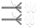
- FIG. 5 is a diagram showing examples of drive waveforms and the relationship between the drive waveforms and changes in the flow path; 7 is a graph for explaining the relationship between the number of times of driving and the occurrence of cavitation;
- FIG. 4 is a diagram for explaining an example of drive waveforms;
- FIG. 5 is a diagram for explaining the relationship between drive time and the amount of suction to the particle fractionation channel;
- FIG. 4 is a diagram showing an example of an operation flow in the biological particle sorting device of the present disclosure; It is a figure which shows an example of the flow of a parameter adjustment process.
- FIG. 5 is a diagram showing an example of the relationship between delay time and yield;
- FIG. 4 is a schematic diagram showing a state in which biological particles are aligned in a line and flow in a traveling direction D in a channel.
- FIG. 3 is a schematic diagram showing a state in which a plurality of sorting target particles are sorted.
- FIG. 3 is a schematic diagram showing a state in which a plurality of sorting target particles are sorted. It is an example of a flow chart of a delay time setting process.
- Biological particle sorting device (1) Description of the first embodiment (2) Example of biological particle sorting device (2-1) Configuration of device and sorting operation (2-2) Flow process (2-3) Judgment process (2-) 4) Collection process (2-5) Bioparticle fractionation microchip and bioparticles (3) Adjustment of drive waveform (3-1) Explanation of drive waveform adjustment for cavitation generation and prevention thereof (3-1-1 ) Occurrence of cavitation accompanying improvement in fractionation efficiency (3-1-2) Usefulness of driving waveform adjustment in setting parameters for fractionation conditions (3-1-3) Relationship between number of times of driving and generation of cavitation (3-1- 4) Relationship between driving time and amount of suction to particle fractionation channel (3-1-5) Basic concept of the present disclosure (3-2) Adjustment of driving waveform based on information on number of fractionation processes (3- 3) Adjustment of drive waveform based on information on the ratio or number of particles to be sorted (3-4) Timing of drive waveform adjustment (3-4-1) Drive waveform adjustment in fractionation condition parameter adjustment step (3-4).
- a bioparticle sorting apparatus includes a pressure change element that changes the pressure in a flow channel in which bioparticles determined to be sorted are collected, and a control unit that drives the pressure change element.
- the control unit is configured to adjust the driving waveform of the pressure change element based on information about the number of fractionation processes per unit time or information about the ratio or number of particles to be fractionated contained in the unit sample. .
- the bioparticle sorting device may be configured as a device for sorting bioparticles in a closed space, for example, as a device for sorting bioparticles by controlling the flow path in which the bioparticles advance. may be configured.
- FIG. 1 shows a configuration example of a biological particle sorting device according to the present disclosure. The figure also shows an example of the channel structure of a bioparticle fractionation microchip (hereinafter also referred to as "microchip") attached to the device.
- FIG. 2 shows an example of a flow chart of the sorting process executed by the biological particle sorting device.
- the bioparticle sorting device 100 further includes a microchip 150 .
- Microchip 150 may be replaceably attached to bioparticle sorting device 150 .
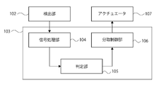
- the control unit 103 can include a signal processing unit 104, a determination unit 105, and a fractionation control unit 106, as shown in FIG.
- the bioparticle sorting microchip 150 will be first described below, and then, while the sorting operation by the biological particle sorting device 100 will be described, other components of the device will be described.
- the biological particle sorting microchip 150 shown in FIG. 1 has a sample liquid channel 152 and a sheath liquid channel 154 that joins the sample liquid channel 152 at a junction 162 .
- the biological particle sorting microchip 150 is further provided with a sample fluid inlet 151 and a sheath fluid inlet 153 .
- a portion of the sheath liquid flow path 154 is indicated by a dotted line.
- the portion indicated by the dotted line is located lower than the sample liquid flow path 152 indicated by the solid line (position shifted in the optical axis direction as indicated by the arrow extending from reference numeral 101 to 102). At the intersection of the flow path indicated by the solid line and the flow path indicated by the solid line, these flow paths do not communicate.
- the sample liquid flow path 152 is shown to bend twice between the sample liquid inlet 151 and the confluence portion 162. This is for facilitating the distinction between The sample liquid flow path 152 may be configured linearly from the sample liquid inlet 151 to the confluence section 162 without such a bend.
- a sample liquid containing bioparticles is introduced from the sample liquid inlet 151 into the sample liquid channel 152, and a sheath liquid containing no bioparticles is introduced from the sheath liquid inlet 153 into the sheath liquid channel 154. be done.
- the biological particle sorting microchip 150 has a confluence channel 155 having a confluence portion 162 at one end.
- the confluence channel 155 includes a fractionation discrimination section 156 used for fractionation discrimination of bioparticles.
- the sample liquid and the sheath liquid merge at the confluence section 162 and flow through the confluence channel 155 toward the particle sorting section 157 .
- the sample liquid and the sheath liquid merge at the confluence portion 162 to form, for example, a laminar flow in which the sample liquid is surrounded by the sheath liquid.
- the biological particles are aligned substantially in a line in the laminar flow.
- a laminar flow is formed containing the bioparticles.
- the biological particle sorting microchip 150 further has a particle sorting section 157 at the other end of the confluence channel 155 .
- FIG. 3 shows an enlarged view of the particle sorting section 157.
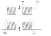
- the confluence channel 155 is connected to the biological particle recovery channel 159 via a connection channel 170, as shown in FIG. 3A.
- the confluence channel 155, the connecting channel 170, and the bioparticle recovery channel 159 may be coaxial.
- a flow entering the bioparticle recovery channel 159 is formed, and the particles to be recovered are recovered into the bioparticle recovery channel 159 .
- the particles to be collected flow through the connection channel 170 to the biological particle recovery channel 159 .
- the biological particles that are not to be collected flow into the particle sorting section 157, the biological particles that are not to be collected flow into the branch channel 158 as shown in FIG. 3C. In this case, no flow entering the biological particle collection channel 159 is formed.
- the biological particle recovery channel 159 extends linearly from the particle sorting section 157, makes a U-turn, and reaches the same plane as the plane formed by the sample liquid inlet 151 and the sheath liquid inlet 153. is formed to The liquid flowing through the biological particle recovery channel 159 is discharged from the recovery channel end 163 to the outside of the chip.
- the two branch channels 158 also extend linearly from the particle sorting section 157, make a U-turn, and extend on the same plane as the sample liquid inlet 151 and the sheath liquid inlet 153 are formed. is designed to reach Liquid flowing through the branch channel 158 is discharged from the branch channel end 160 to the outside of the chip.
- the biological particle recovery channel 159 is changed from a solid line to a dotted line at the U-turn portion. This change indicates that the position in the direction of the optical axis changes during the change. By changing the position in the optical axis direction in this way, the biological particle recovery channel 159 and the branched channel 158 are not communicated with each other at the intersection with the branched channel 158 .
- Both the collection channel end 163 and the two branch channel ends 166 are formed on the surface where the sample fluid inlet 151 and the sheath fluid inlet 153 are formed.
- an introduction channel inlet 164 for introducing liquid into an introduction channel 161, which will be described later, is also formed on the surface.
- the biological particle sorting microchip 150 has an inlet into which liquid is introduced and an outlet from which liquid is discharged, all of which are formed on one surface. This facilitates attachment of the chip to the biological particle sorting device 100 . For example, compared to the case where inlets and/or outlets are formed on two or more surfaces, the connection between the channel provided in the biological particle sorting device 100 and the channel of the biological particle sorting microchip 150 becomes easier.
- the biological particle sorting microchip 150 has an introduction channel 161 for introducing a liquid to the connection channel 170, as shown in FIGS. By introducing the liquid from the introduction channel 161 into the connection channel 170, the inside of the connection channel 170 is filled with the liquid. This can prevent unintended biological particles from entering the biological particle recovery channel 159 .
- the bioparticle sorting microchip 150 has two branch channels 158 connected to the confluence channel 155 at the other end of the confluence channel 155 .
- the confluence channel may branch into the connection channel and the at least one branch channel. Bioparticles other than the particles to be collected flow into either of the two branch channels 158 without entering the bioparticle recovery channel 159 .
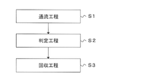
- the bioparticle sorting operation using the bioparticle sorting microchip 150 consists of a flow step S1 in which the liquid containing the bioparticles flows into the confluence channel 155, and a flow step S1 of the bioparticles flowing through the confluence channel 155. It includes a determination step S2 of determining whether the particles are collection target particles and a collection step S3 of collecting the collection target particles into the bioparticle collection channel 159 . Each step will be described below.
- the sample liquid containing bioparticles and the sheath liquid not containing bioparticles are introduced from the sample liquid inlet 151 and the sheath liquid inlet 153 into the sample liquid flow path 152 and the sheath liquid flow path 154, respectively.
- the sample liquid may be, for example, a biological sample containing biological particles, in particular a biological sample containing biological particles such as cells.
- the biological particles are aligned substantially in a line in the laminar flow. That is, in the flow-through step S1, a laminar flow containing bioparticles flowing substantially in a line can be formed.
- the liquid containing bioparticles is flowed through the confluence channel 155, particularly as a laminar flow.
- the liquid flows through the confluence channel 155 from the confluence portion 162 toward the particle sorting portion 157 .
- the determination step S2 it is determined whether the biological particles flowing through the confluence channel 155 are particles to be collected.
- the determination can be made by the determination unit 105 .
- the determination unit 105 can make the determination based on the light generated by the light irradiation of the biological particles by the light irradiation unit 101 .
- An example of the determination step S2 is described in more detail below.
- the light irradiation unit 101 irradiates the bioparticles flowing through the confluence channel 155 (particularly, the fractionation determination unit 156) in the bioparticle fractionation microchip 150 with light (for example, excitation light).
- the detection unit 102 detects the light generated by the light irradiation.
- the determination unit 105 determines whether the biological particles are particles to be collected. For example, the determination unit 105 can perform determination based on scattered light, determination based on fluorescence, or determination based on an image (for example, a dark field image and/or a bright field image).
- the particles to be recovered are recovered into the bioparticle recovery channel 159 by controlling the flow in the bioparticle sorting microchip 150 by the control unit 103 .
- the light irradiator 101 irradiates the bioparticles flowing in the channel in the microchip 150 for sorting bioparticles with light (excitation light, for example).
- the light irradiation unit 101 can include a light source that emits light and an objective lens that collects the excitation light on the biological particles flowing through the fractionation determination unit.
- the light source may be appropriately selected by those skilled in the art depending on the purpose of analysis, and may be, for example, a laser diode, an SHG laser, a solid state laser, a gas laser, a high brightness LED, or a halogen lamp, or two of these. A combination of the above may also be used.
- the light irradiation section may contain other optical elements as necessary.
- the detection unit 102 detects scattered light and/or fluorescence generated from the bioparticles by light irradiation by the light irradiation unit 101 .
- the detection unit 102 may include a condenser lens and a detector that collect fluorescence and/or scattered light generated from biological particles.
- a PMT, a photodiode, a CCD, a CMOS, and the like can be used as the detector, but are not limited to these.
- the detection unit 102 may include other optical elements as needed in addition to the condenser lens and detector.
- the detection unit 102 can further include, for example, a spectroscopic unit.
- the spectroscopic section can detect light of a wavelength to be detected separately from light of other wavelengths.
- the detection unit 102 can convert the detected light into an analog electric signal by photoelectric conversion.
- the detection unit 102 can further convert the analog electric signal into a digital electric signal by AD conversion.
- the detection unit 102 may acquire an image generated by light irradiation by the light irradiation unit 101.
- the images may be, for example, dark field images, bright field images, or both.
- the light irradiation section 101 may include, for example, a halogen lamp or laser, and the detection section 102 may include a CCD or CMOS.
- the detection unit 102 may be, for example, an imaging device in which a substrate in which a CMOS sensor is incorporated and a substrate in which a DSP (Digital Signal Processor) is incorporated are laminated.
- DSP Digital Signal Processor
- the detection unit 102 including the imaging device can determine whether the biological particles are particles to be collected based on, for example, a learning model. Also, the learning model may be updated in real time while the method according to the present disclosure is being performed. For example, a DSP can perform machine learning processing while resetting a pixel array section in a CMOS sensor, exposing the pixel array section, or reading pixel signals from each unit pixel of the pixel array section.
- a DSP can perform machine learning processing while resetting a pixel array section in a CMOS sensor, exposing the pixel array section, or reading pixel signals from each unit pixel of the pixel array section.
- An example of an imaging device that operates as an AI sensor is the imaging device described in International Publication No. 2018/051809.
- a signal processing unit 104 included in the control unit 103 processes the waveform of the digital electric signal obtained by the detection unit 102 to generate information (data) regarding the characteristics of light used for determination by the determination unit 105. sell.
- the signal processing unit 104 extracts one, two, or three of the width of the waveform, the height of the waveform, and the area of the waveform from the waveform of the digital electrical signal. can be obtained.
- the information about the characteristics of the light may include, for example, the time when the light was detected.
- the processing by the signal processing unit 104 described above can be performed particularly in an embodiment in which the scattered light and/or fluorescence are detected.
- a determination unit 105 included in the control unit 103 determines whether the biological particles flowing in the flow path are particles to be collected, based on the light generated by irradiating the biological particles flowing in the flow path.
- the waveform of the digital electrical signal obtained by the detector 102 is processed by the controller 103, and based on the information about the characteristics of the light generated by the processing, , the determining unit 105 determines whether the biological particles are particles to be collected. For example, in the determination based on scattered light, features of the external shape and/or internal structure of the bioparticle may be specified, and whether the bioparticle is the recovery target particle may be determined based on the feature.
- bioparticles such as cells
- bioparticles such as cells
- by labeling bioparticles such as cells with antibodies or dyes (especially fluorescent dyes) it is possible to determine whether the bioparticles are particles to be collected based on the characteristics of the surface antigens of the bioparticles.
- the determination unit 105 included in the control unit 103 determines that the biological particles are recovery target particles based on the acquired images (for example, dark field images, bright field images, or both). Determine if there is For example, based on one or a combination of two or more of the morphology, size, and color of the bioparticles (especially cells), it can be determined whether the bioparticles are particles to be collected.
- the determination can be made, for example, by whether the information about the characteristics of the light satisfies a pre-specified criterion.
- the criterion may be a criterion indicating that the biological particles are particles to be collected.
- the criteria may be appropriately set by those skilled in the art, and may be criteria relating to light characteristics, such as criteria used in technical fields such as flow cytometry.
- One position in the fractionation discrimination section 156 may be irradiated with one light, or each of a plurality of positions in the fractionation discrimination section 156 may be irradiated with light.
- the microchip 150 can be configured such that light is applied to each of two different positions in the preparative discrimination section 156 (i.e., there are two positions in the preparative discrimination section 156 that are illuminated with light). be.). In this case, for example, based on light (for example, fluorescence and/or scattered light) generated by irradiating the bioparticle at one position, it can be determined whether the bioparticle is a particle to be collected.
- the velocity of the biological particles in the flow channel calculates the velocity of the biological particles in the flow channel.
- the distance between the two irradiation positions may be determined in advance, and the velocity of the bioparticle can be determined based on the difference between the two detection times and the distance.
- the velocity it is possible to accurately predict the arrival time at the particle sorting section 157, which will be described below. By accurately predicting the arrival time, it is possible to optimize the timing of formation of the flow entering the biological particle recovery channel 159 (in particular, the timing of driving the pressure change element 107).
- a predetermined threshold value can also determine not to collect the certain bioparticle.
- the distance between the certain bioparticle and the preceding or succeeding bioparticle is small, the possibility that the preceding or succeeding bioparticle is collected together during the aspiration of the certain bioparticle increases. .
- the certain bioparticle is not to be recovered when the probability of being collected together is high, it is possible to prevent the bioparticle before or after the bioparticle from being recovered. As a result, the purity of the target bioparticles among the collected bioparticles can be increased.
- a specific example of a microchip that is irradiated with light at two different positions in the fractionation determination unit 156 and a device including the microchip is described in, for example, Japanese Patent Application Laid-Open No. 2014-202573.
- control unit 103 may control light irradiation by the light irradiation unit 101 and/or light detection by the detection unit 102 .
- control unit 103 can control driving of a pump for supplying fluid into the bioparticle fractionation microchip 150 .
- the control unit 103 may be composed of, for example, a hard disk storing a program and an OS for causing the biological particle sorting apparatus 100 to execute the biological particle sorting method according to the present disclosure, a CPU, and a memory.
- the functions of the control unit 103 can be implemented in a general-purpose computer.
- the program may be recorded in a recording medium such as a microSD memory card, an SD memory card, or a flash memory.
- a drive (not shown) provided in the biological particle sorting apparatus 100 reads the program recorded on the recording medium, and the control unit 103 performs biological particle separation according to the read program.
- the collection device 100 may be caused to perform the biological particle collection method according to the present disclosure.
- the bioparticles determined to be the particles to be recovered in the determination step S2 are recovered into the bioparticle recovery channel 159.
- the collection step S3 is performed in the particle sorting section 157 in the microchip 150 .
- the particle sorting section 157 the laminar flow that has flowed through the confluence channel 155 splits into two branch channels 158 .
- the particle sorting section 157 shown in FIG. 1 has two branch channels 158, the number of branch channels is not limited to two.
- the particle sorting section 157 may be provided with, for example, one or a plurality of (for example, two, three, four, etc.) branch channels.
- the branch channel may be configured to branch in a Y shape on one plane as in FIG. 1, or may be configured to branch three-dimensionally.
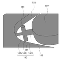
- FIGS. 5A and 5B Enlarged views of the vicinity of the connecting channel 170 are shown in FIGS. 5A and 5B.
- FIG. 5A is a schematic perspective view of the vicinity of the connecting channel 170.
- FIG. 5B is a schematic cross-sectional view of a plane passing through the center line of the introduction channel 161 and the center line of the connection channel 170.
- FIG. The connecting channel 170 includes a channel 170a (hereinafter also referred to as upstream connecting channel 170a) on the side of the fractionation determination unit 156 and a channel 170b (hereinafter referred to as downstream connecting channel 170b) on the biological particle recovery channel 159 side. ), and a connecting portion 170 c between the connection channel 170 and the introduction channel 161 .
- upstream connecting channel 170a on the side of the fractionation determination unit 156
- a channel 170b hereinafter referred to as downstream connecting channel 170b
- the introduction channel 161 is provided so as to be substantially perpendicular to the channel axis of the connection channel 170 .
- two introduction channels 161 are provided facing each other at substantially the center position of the connection channel 170, but only one introduction channel may be provided.
- the cross-sectional shape and dimensions of the upstream connection channel 170a may be the same as the shape and dimensions of the downstream connection channel 170b.
- both the cross-section of the upstream connecting channel 170a and the cross-section of the downstream connecting channel 170b may be substantially circular with the same dimensions.
- both of these two cross-sections may be rectangular (eg, square or rectangular, etc.) with the same dimensions.
- Liquid is supplied from the two introduction channels 161 to the connection channel 170 as indicated by the arrows in FIG. 5B.
- the liquid flows from the connecting portion 170c to both the upstream connecting channel 170a and the downstream connecting channel 170b.
- the liquid flows as follows.
- the liquid that has flowed to the upstream connection channel 170 a flows out of the connecting surface of the connection channel 170 to the confluence channel 155 and then flows separately into two branch channels 158 . Since the liquid is discharged from the connection surface in this way, the liquid and biological particles that do not need to be collected into the biological particle collection channel 159 pass through the connection channel 170 to the biological particle collection channel 159. can be prevented from entering.
- the liquid that has flowed to the downstream connection channel 170 b flows into the biological particle recovery channel 159 . As a result, the inside of the biological particle recovery channel 159 is filled with the liquid.
- the liquid can be supplied from the two introduction channels 161 to the connection channel 170 .
- the bioparticle recovery channel 159 passes from the confluence channel 155 through the connection channel 170 to the bioparticle recovery channel 159 .
- a stream is formed that flows to That is, a flow is formed that flows from the confluence channel 155 to the biological particle recovery channel 159 through the upstream connection channel 170a, the connection part 170c, and the downstream connection channel 170b in this order.
- the particles to be collected are collected in the bioparticle collection channel 159 .
- connection channel 180 includes a channel 180a on the side of the fractionation discrimination section 156 (hereinafter also referred to as an upstream connection channel 180a) and a channel 180b on the side of the biological particle recovery channel 159. (hereinafter also referred to as a downstream connection channel 180 b ), and a connecting portion 180 c between the connection channel 180 and the introduction channel 161 .
- Both the cross section of the upstream connection channel 180a and the cross section of the downstream connection channel 180b have a substantially circular shape, but the diameter of the latter cross section is larger than the diameter of the former cross section.
- the bioparticle collection channel 159 can receive more bioparticles immediately after the bioparticle sorting operation by the negative pressure described above. It is possible to more effectively prevent the particles to be collected that have already been fractionated from being released into the confluence channel 155 through the connection channel 180 .
- both the cross section of the upstream connection channel 180a and the cross section of the downstream connection channel 180b are rectangular, by making the area of the latter cross section larger than the area of the former cross section, As described above, it is possible to more effectively prevent already collected biological particles from being released into the confluence channel 155 through the connecting channel 180 .
- the particles to be recovered are recovered into the bioparticle recovery channel through the connection channel.
- Such collection may be performed, for example, by creating a negative pressure within the biological particle collection channel 159, as described above.
- the negative pressure is generated by a pressure change element (also referred to as an actuator) 107 attached to the outside of the microchip 150, which deforms the wall defining the biological particle recovery channel 159.
- Pressure change element 107 may be, for example, a piezo actuator.
- the negative pressure can create the flow into the biological particle collection channel 159 .
- the pressure change element 107 can be attached to the outside of the microchip 150, as shown in FIG. Due to the deformation of the wall, the inner space of the biological particle collection channel 159 can be changed to generate a negative pressure.
- Pressure change element 107 can be, for example, a piezo actuator.
- An introduction channel 161 is provided in the connection channel 170 to prevent bioparticles that are not particles to be collected from entering the bioparticle recovery channel 159 through the connection channel 170 .
- a liquid is introduced into the connection channel 170 from the introduction channel 161 .
- the connecting channel 170 is filled with the liquid.
- a part of the liquid forms a flow from the connection channel 170 toward the confluence channel 155 , thereby preventing bioparticles other than the particles to be recovered from entering the bioparticle recovery channel 159 .
- the liquid that forms the flow from the connection channel 170 to the confluence channel 155 does not flow in the confluence channel 155 due to the flow of the liquid flowing in the confluence channel 155 to the branch channel 158 . flow through the branch flow path 158 to.
- the rest of the liquid introduced into the connecting channel 170 flows into the biological particle recovery channel 159 . Thereby, the inside of the biological particle recovery channel 159 can be filled with the liquid.
- the flow that has flowed to the branch channel 158 can be discharged to the outside of the microchip at the branch channel end 160 .
- the recovery target particles recovered to the biological particle recovery channel 159 can be discharged to the outside of the microchip at the recovery channel end 163 .
- a container can be connected to the collection channel end 163 via a channel such as a tube. The particles to be collected may be collected in the container.
- the confluence channel, the connection channel, and the recovery channel may be arranged linearly.
- the connection channel and the recovery channel are arranged at an angle with respect to the confluence channel. Therefore, the recovery process can be performed more efficiently. For example, the amount of suction required to guide the particles to be collected to the connecting channel can be reduced.
- the bioparticles are aligned substantially in a line in the confluence channel and flow toward the connection channel. Therefore, it is also possible to reduce the amount of suction in the recovery process.
- liquid is supplied from the introduction channel to the connection channel.
- a flow is formed in the connection channel that flows from the connection position between the introduction channel and the connection channel toward the confluence channel, and the liquid flowing in the confluence channel flows into the connection channel. It is possible to prevent bioparticles other than the particles to be recovered from flowing into the recovery channel through the connecting channel.
- the particles to be recovered pass through the connection channel and are recovered into the recovery channel by, for example, the negative pressure generated in the recovery channel. .
- micro means that at least a part of the channel included in the bioparticle sorting microchip has dimensions on the order of ⁇ m, particularly cross-sectional dimensions on the order of ⁇ m. . That is, in the present disclosure, the term “microchip” refers to a chip including channels on the order of ⁇ m, particularly a chip including channels having cross-sectional dimensions on the order of ⁇ m. For example, a chip that includes a particle sorting section composed of channels having cross-sectional dimensions on the order of ⁇ m can be called a microchip according to the present disclosure.
- the cross section of the confluence channel 155 is, for example, rectangular, and the width of the confluence channel 155 is, for example, 100 ⁇ m to 500 ⁇ m, particularly 100 ⁇ m to 300 ⁇ m.
- the width of the branch flow path branched from the merged flow path 155 may be smaller than the width of the merged flow path 155 .
- the cross section of the connecting channel 170 is, for example, circular, and the diameter of the connecting channel 170 at the junction of the connecting channel 170 and the confluence channel 155 can be, for example, 10 ⁇ m to 60 ⁇ m, particularly 20 ⁇ m to 50 ⁇ m. These dimensions of the channel may be changed as appropriate according to the size of the biological particles, particularly the size of the particles to be collected.
- the bioparticle fractionation microchip 150 can be manufactured by a method known in the art.
- the biological particle sorting microchip 150 can be manufactured by bonding together two or more substrates each having a predetermined flow path.
- the channel may be formed on all of two or more substrates (especially two substrates), or may be formed on some of the two or more substrates (especially on one of the two substrates). It may be formed only on one sheet).
- the flow path is formed only in one substrate.
- two flow paths are provided at different positions in the optical axis direction (so as not to communicate with each other) and to intersect when viewed from the optical axis direction.
- the flow channel structure can be created by stacking three or more substrates provided with flow channels.
- Materials known in this technical field can be used as materials for forming the bioparticle fractionation microchip 150 .
- Examples include, but are not limited to, polycarbonates, cycloolefin polymers, polypropylene, PDMS (polydimethylsiloxane), polymethyl methacrylate (PMMA), polyethylene, polystyrene, glass, and silicon.
- polymeric materials such as polycarbonate, cycloolefin polymers, and polypropylene are particularly preferred because of their excellent processability and the ability to inexpensively manufacture microchips using molding equipment.
- the bioparticle fractionation microchip 150 is preferably transparent.
- the biological particle fractionation microchip 150 is transparent at least in a portion through which light (laser light and scattered light) passes, and for example, the fractionation discrimination portion may be transparent.
- the entire biological particle sorting microchip 150 may be transparent.
- the channel group is not formed in the microchip 150 in the present disclosure.
- the channels may be formed in a substrate such as plastic or glass.
- the flow path group may have a two-dimensional or three-dimensional structure.
- the bioparticles may be particles having dimensions that allow them to flow through the channels in the bioparticle sorting microchip.
- bioparticles may be appropriately selected by those skilled in the art.
- bioparticles include biological bioparticles such as cells, cell masses, microorganisms, exosomes, and liposomes.
- the bioparticle sorting apparatus for example, gel particles, beads, latex particles, polymer particles, industrial particles, etc., for optimizing the setting of sorting conditions performed before the bioparticle sorting operation. of synthetic bioparticles may be subjected to a sorting operation.
- Bioparticles can include chromosomes, liposomes, mitochondria, organelles (cell organelles), etc. that constitute various cells.
- Cells can include animal cells (such as blood cells) and plant cells. The cells may in particular be blood lineage cells or tissue lineage cells. The blood lineage cells may be suspension lineage cells such as T cells and B cells.
- the tissue cells may be, for example, adherent cultured cells or adherent cells dissociated from a tissue.
- Cell masses can include, for example, spheroids and organoids.
- Microorganisms can include bacteria such as E. coli, viruses such as tobacco mosaic virus, fungi such as yeast, and the like.
- biological bioparticles can also include biological macromolecules such as nucleic acids, proteins, complexes thereof, and the like. These biological macromolecules may be, for example, extracted from cells or contained in blood or other liquid samples.
- the shape of the bioparticles may be spherical, approximately spherical, or non-spherical.
- the size and mass of the bioparticle can be appropriately selected by those skilled in the art depending on the size of the channel of the microchip. On the other hand, the size of the channel of the microchip can also be appropriately selected according to the size and mass of the bioparticle.
- bioparticles may optionally be attached with chemical or biological labels, such as fluorescent dyes or fluorescent proteins. The label may make the bioparticle easier to detect.
- Labels to be attached can be appropriately selected by those skilled in the art.
- a molecule eg, antibody, aptamer, DNA, RNA, etc.
- said bioparticles may be cells, in particular cells.
- the sample to be sorted by the biological particle sorting apparatus of the present disclosure may be, for example, a biological sample, particularly a biological sample containing cell populations, more particularly a biological sample containing immune cell populations. you can The cell population can particularly include cells to be sorted and cells not to be sorted.
- the bioparticle sorting device described in (2) above sorts the bioparticles determined to be sorted by driving the pressure change element 107 .
- the control unit included in the biological particle sorting apparatus controls the amount of light collected near a certain biological particle even if the characteristics of the light generated from the biological particle indicate that the biological particle is to be collected. If there are other bioparticles that should not be sorted, it may be configured to determine not to perform sorting of the certain bioparticles in order to prevent sorting of the other bioparticles.
- the fractionation efficiency be as high as possible.
- shortening the drive time of the pressure change element 107 is conceivable in order to increase the sorting efficiency.
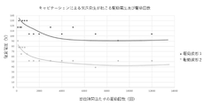
- cavitation occurs when the drive time is short, for example, when the number of fractionation processes per unit time (e.g., corresponding to the number of times the pressure change element is driven) is large.
- the present inventors found that adjustment of the drive waveform based on information on the number of fractionation processes per unit time or information on the ratio or number of particles to be fractionated contained in the unit sample is useful for preventing cavitation. I found out. By adjusting the driving waveform, it is possible to prevent the occurrence of cavitation and improve the fractionation efficiency.
- the first drive waveform and the second drive waveform may have hold times different from each other or may have the same hold time. Also, the first drive waveform and/or the second drive waveform may not have a hold time.
- the hold time of these drive waveforms may be, for example, 0 ⁇ s or longer, 3 ⁇ s or longer, or 5 ⁇ s or longer.
- the hold time for these drive waveforms may be 20 ⁇ s or less, 15 ⁇ s or less, or 10 ⁇ s or less.
- the hold time can be selected, for example, depending on the amount of suction desired. The longer the hold time, the greater the amount of suction and the higher the collection rate of the particles to be separated, but the possibility of collecting the particles before and after the particles to be separated also increases accordingly.
- the ratio or number of particles to be sorted contained in the unit sample may be the ratio or number acquired by the biological particle sorting device as described above, or may be the estimated ratio or number.
- the estimated ratio or number is calculated based on the ratio or number of particles to be separated contained in a certain amount of sample and the relationship between the certain amount and the amount of the unit sample. good.
- the step-down time, step-up time, or both may be changed.
- the control unit lengthens the voltage decrease time, the voltage increase time, or both.
- the controller shortens the step-down time, the step-up time, or both, when the ratio or number is less than a predetermined value (or less than or equal to a predetermined value).
- the controller may select, for example, any one of three or more drive waveforms according to the ratio or number.
- the three or more drive waveforms may differ in drive time, the first drive waveform having the longest drive time, the second drive waveform having the shortest drive time, and the two drive waveforms having the shortest drive time. and one or more other drive waveforms with drive times between.
- the control unit adopts the first drive waveform when the ratio or number is greater than or equal to a first predetermined value (or exceeds the first predetermined value), value (or equal to or less than a second predetermined value), the second driving waveform may be adopted.
- the control section may adopt any one of the one or more other drive waveforms when the ratio or number is between the first predetermined value and the second predetermined value.
- a parameter adjustment step S201 is performed to adjust parameters, and then a fractionation treatment step S202 of fractionating the particles to be fractionated contained in the biological sample using the fractionation condition parameters set in the adjustment step.
- the control section may perform the drive waveform adjustment described above in the parameter adjustment step or in the biological sample preparative processing step.
- delay time and guard time can be cited as the fractionation condition parameters.
- the control unit controls information about the number of fractionation processes per unit time or information about the ratio or number of particles to be fractionated contained in the unit sample,
- the drive time is adjusted based on the drive voltage set to apply to the process.
- the drive voltage set for application to the fractionation process may be set in advance in the bioparticle fractionation device before executing the drive waveform setting step S301, or It may be preset by the user of the capture device. It is preferable to perform such drive time adjustment processing in the parameter adjustment process, particularly in the drive waveform setting process. As a result, parameter optimization in the delay time setting process and/or the guard time setting process, which will be described later, can be performed with higher accuracy.
- the delay time is set using the driving waveform set in the driving waveform setting step S301.
- the biological particle sorting device performs sorting on a portion of the biological sample subjected to the sorting process.
- the control unit acquires the relationship between the delay time and the yield in the fractionation process. For example, the relationship between delay time and yield (recovery) as shown in FIG. 14 is obtained.
- the controller selects a delay time that achieves a predetermined yield based on the relationship. For example, the control section selects one of the delay times that maximizes the yield as a parameter to be used in the next preparative treatment step.
- the driving waveform setting step S301 may be executed.
- the control unit acquires the information used for drive waveform adjustment by executing the fractionation process executed to acquire the relationship between the delay time and the yield. Then, based on the acquired information, the control unit may perform the drive waveform adjustment as described above. Further, the drive waveform setting step S301 may be performed after the delay time setting step S302 is performed.
- the delay time setting process may include coarse adjustment processing (steps S401 to S406) and fine adjustment processing (steps S407 to S412).
- step S401 the control unit starts rough adjustment processing of the delay time.
- the control unit identifies the provisional delay time.
- the provisional delay time is, for example, a value selected from the range of delay times in which the yield is equal to or greater than the first predetermined value (for example, the median value or weighted average value of the delay times in the range, or the maximum yield). delay time).
- the control unit identifies a range of delay times in which the yield is 75% or more, and identifies the median value within that range as the tentative delay time.
- the control unit acquires the first margin.
- the first margin may be the range of delay times for which the yield is greater than or equal to the second predetermined value.
- the second predetermined value is a value greater than the first predetermined value referred to in step S403.
- the control unit specifies a delay time range in which the yield is 85% or more as the first margin.
- step S405 the control unit calculates a provisional speed compensation coefficient for automatically correcting variations in particle flow speed based on the provisional delay time.
- the velocity of particles flowing through the channel may vary from particle to particle. Therefore, the control unit performs a process of automatically compensating the particle velocity using the velocity compensation coefficient according to the particle velocity.
- step S408 the control unit adjusts the driving waveform applied in the sorting operation based on the first margin.
- the controller adjusts the drive voltage and/or the hold time among the components of the drive waveform.
- the biological particle sorting device executes a sorting operation using the temporary delay time and the drive waveform.
- the control unit determines to sort the biological particles, and the biological particles outside the range of the first margin If particles are present, it is determined that the bioparticles are not collected.
- the control unit acquires the second margin.
- the second margin may be the range of delay times for which the yield is greater than or equal to a third predetermined value.
- the third predetermined value may be the same as the second predetermined value, but may be higher or lower than the second predetermined value.
- the control unit specifies a delay time range in which the yield is continuously 85% or more as the second margin.
- the control unit identifies the best delay time from among the second margins.
- the best delay time may be, for example, a value selected from the second margins.
- the value may, for example, be the weighted average or median value of the delay times within the second margin, or the delay time within the second margin for which the yield is maximized.
- the control unit specifies a weighted average value of delay times for which the yield is 85% or more as the best delay time.
- the best delay time is used in the fractionation processing step S202.
- step S412 the control unit terminates the fine adjustment process.
- the fluid (especially liquid) present in the predetermined area containing the particles to be sorted is recovered in the biological particle recovery channel 159 .
- the region R1 shown in the upper part of FIG. 11 is recovered.
- the other particles are also present in the biological particle recovery channel 159. This can lead to a reduction in the purity of the particles to be sorted. Whether other particles exist in the same region is determined by the time when the light generated by the light irradiation to the particle to be fractionated was detected and the light irradiation to other particles flowing in front of or behind the particle.
- the control unit When adjusting the initial guard time, acquires the yield when using the post-change guard time obtained by adding a predetermined value to the initial guard time. The control unit performs the same determination as above for the yield, and sets the post-change guard time as the guard time to be used in the fractionation treatment step S202 when a predetermined condition is satisfied.
- the biological particle sorting device executes the delay time setting step and/or the guard time setting step after executing the drive waveform setting step.
- the delay time and/or the guard time can be set while the influence of cavitation is removed or reduced. Therefore, better parameters can be adopted for subsequent preparative processing steps.
- the biological particle sorting device executes the sorting process step S202 using the sorting condition parameters set in the parameter adjustment step.
- the biological particle sorting device according to the present disclosure may perform the drive waveform adjustment described above in the sorting process. For example, by adjusting the driving waveform in the process of performing the fractionation process, it is possible to perform an appropriate fractionation operation according to the state of the sample, thereby speeding up the fractionation process, for example.
- the parameter adjustment step may include a delay time setting step.
- the biological particle sorting apparatus may be configured to execute delay time adjustment processing in the delay time setting step.
- the biological particle sorting device may be configured to measure the yield represented by the number of sorted particles with respect to the number of sorting operations in the delay time adjustment process. By measuring the yield, it is possible to optimize the delay time.
- the biological particle sorting device in the yield measurement, only when other biological particles do not exist within a predetermined range around the biological particles determined to be sorted is configured to perform a sorting operation on the It is undesirable for particles other than the particles determined to be fractionated to be fractionated in the yield measurement performed for setting the delay time. Therefore, by performing the sorting operation and measuring the yield only in the above case, it is possible to improve the setting accuracy of the delay time.
- a region Rs is a region recovered to the biological particle recovery channel 159 when the shifted delay time is employed.
- the bioparticle sorting device performs the sorting operation for the particles Pt only when other bioparticles do not exist in the region Rs in the yield measurement.
- the relationship between the delay time and the yield can be more accurately grasped, and the delay time setting accuracy can be improved.
- the drive waveform adjustment according to the present disclosure may be performed in the preparative processing step as described in (3-4-2) above.
- the control unit may perform the drive waveform adjustment for each predetermined portion of the sample, or for each particle contained in the sample. This makes it possible to adjust the drive waveform in real time.
- the control section may have parameters such as an optimum delay time in advance for each adopted drive waveform. This enables more efficient drive waveform adjustment.
- a single sample may contain multiple types of particles to be fractionated.
- a fractionation operation for fractionating a plurality of types of particles to be fractionated may be performed in one fractionation operation.
- the drive waveform adjustment according to the present disclosure may be performed when performing a fractionation operation for fractionating a plurality of types of particles to be fractionated. It may be performed when one sorting operation is performed.
- the control unit may adjust the drive waveform of the pressure change element based on information about the number of fractionation processes per unit time.
- the number of times of fractionation processing may be the sum of the number of times of fractionation processing of the plurality of types of particles to be fractionated. The sum may mean the total number of fractionation processing times for each particle to be fractionated.
- the number of times of fractionation processing may be the number of times of fractionation processing of any one or two or more of the plurality of types of particles to be fractionated. In this case, for example, based on the number of times of fractionation processing for any one or two or more particles to be fractionated and the composition ratio of any one or two or more particles to be fractionated, the drive Waveform adjustments may be made.
- the denominator of the composition ratio may be the number of the plurality of types of particles to be separated, that is, the composition ratio is the number of the plurality of types of particles to be separated, which is either one or two. It may mean the ratio of the number of particles to be sorted which is one or more.
- the control unit adjusts the drive waveform to or may be performed during the fractionation operation. In the latter case, the control unit may adjust the drive waveform in response to a change in the particles to be sorted during the sorting operation. For example, the control unit may adjust the driving waveform in the parameter adjusting step S201 described above, or may adjust the driving waveform in the fractionation processing step S202.
- both the first particles to be fractionated and the second particles to be fractionated are to be fractionated at first.
- Control can be executed such that only the other particle is subjected to fractionation without subjecting the one particle to fractionation. This sorting operation is described below with reference to FIG.
- first particles to be separated and second particles to be sorted are sorted at a predetermined ratio.
- first particles to be sorted and the second particles to be sorted are sorted into the bioparticle recovery channel 159, and the other particles are sorted into the branch channel. proceed to When a predetermined number of the first particles to be sorted are recovered, sorting of the first particles to be sorted becomes unnecessary in order to achieve the predetermined ratio.
- the control unit changes the particles to be separated to only the second particles to be separated. After the change, as shown in FIG. 16B, only the second particles to be sorted are sorted into the particle sorting channel, and the first particles to be sorted and the other particles advance to the branch channel. do.
- the number of fractionation processes per unit time is different.
- the ratio or number of particles to be fractionated contained in the unit sample is also different.
- the biological body is fractionated such that 100 of each of these two types of particles are fractionated.
- a particle sorter performs a sorting operation. In the sorting operation, 100 first particles to be sorted are sorted, but the number of second sorted particles to be sorted may not reach 100 in some cases. In this case, fractionation of the first particles to be fractionated becomes unnecessary, and it becomes necessary to fractionate only the second particles to be fractionated. Therefore, the sorting target is changed from both the first sorting target particles and the second sorting target particles to only the second sorting target particles.
- the biological particle sorting device of the present disclosure may adjust the drive waveform during the sorting operation.
- the control unit may change the information regarding the number of fractionation processes per unit time or the information regarding the ratio or number of particles to be fractionated contained in the unit sample during the fractionation operation. Waveform adjustments may be performed.
- the control unit can shorten the drive time according to the reduction in the number of preparative collection processes or the ratio or number due to the change.
- the control The unit adjusts the driving waveform during the fractionating operation.
- the control unit may adjust the drive waveform in response to a change in the particles to be sorted during the sorting operation.
- the particles to be sorted are removed after the first sorting operation of fractionating one type of particles to be sorted.
- a second sorting operation for sorting another type of sorting target particles is performed on the sample.
- a fractionation operation is performed on a biological sample S containing first particles to be fractionated (white), second particles to be fractionated (gray), and other particles (black).
- first fractionation operation as shown in FIG. 17A, only the first fractionation target particles are fractionated into the biological particle recovery channel 159, and the second fractionation target particles and other particles are Proceed to the branch channel.
- the second sorting operation as shown in FIG. 17B, the particles to be sorted are sorted into the biological particle recovery channel 159, and the other particles proceed to the branch channel.
- the number of times of fractionation processing per unit time differs between the first fractionation operation and the second fractionation operation.
- the ratio or number of particles to be sorted contained in the unit samples of the samples subjected to the first sorting operation and the second sorting operation is also different.
- the control unit when the biological particle sorting device performs a plurality of sorting operations in order to sort a plurality of types of particles to be sorted at a predetermined ratio, performs adjustment of the driving waveform before performing each sorting operation.
- the control unit may adjust the drive waveform in response to a change in the particles to be sorted during the sorting operation.
- the control unit changes the execution conditions of the fractionation operation according to the replacement of the microchip, the change of the sample, the change of the environment in which the fractionation operation is executed.
- Said drive waveform adjustment may be performed on a case-by-case basis or for each sorting run. Thereby, an optimum drive waveform can be selected for each sorting operation.
- the control unit changes the execution conditions of the fractionation operation according to the replacement of the microchip, the change of the sample, the change of the environment in which the fractionation operation is executed.
- the threshold may be changed on a case-by-case basis or for each sorting operation. This makes it possible to perform appropriate drive waveform adjustment according to various environments.
- the purity of the particles to be sorted contained in the particles recovered to the biological particle recovery channel 159 can be changed as appropriate, for example, according to user's needs. Depending on the purity, the preparative parameters can be changed. Therefore, the control unit may adjust the drive waveform according to the purity of the particles to be fractionated.
- the control unit may adjust the drive waveform based on information regarding the occurrence of cavitation (hereinafter also referred to as "cavitation information").
- the cavitation information may be acquired by imaging a location where cavitation may occur, such as the biological particle recovery channel 159, for example. Alternatively, it may be obtained by irradiating the location with light. For example, bubbles generated by cavitation are irradiated with light, and the generation of bubbles can be detected based on the light generated by the light irradiation.
- the biological particle sorting device of the present disclosure may include, for example, an imaging device configured to image the location.
- the biological particle sorting apparatus of the present disclosure may include, for example, a light irradiation unit that irradiates the location with light and a detection unit that detects the light generated by the light irradiation. . Since the description of the light irradiation section 101 and the detection section 102 described in (2) above applies to the light irradiation section and the detection section, the description thereof will be omitted.
- the present disclosure also provides a method for adjusting collection conditions in a biological particle collection device.
- the method includes a drive waveform adjustment step of adjusting a drive waveform of a pressure change element that changes the pressure in the flow channel in which the bioparticles determined to be sorted are collected.
- the drive waveform adjustment step the drive waveform of the pressure change element is adjusted based on information about the number of fractionation processes per unit time or information about the ratio or number of particles to be fractionated contained in the unit sample.
- the adjustment method can prevent the occurrence of cavitation. Furthermore, it is also possible to maximize the fractionation efficiency while preventing the occurrence of cavitation.
- the method for adjusting preparative conditions is, for example, the above 1. may correspond to the parameter adjusting step S201 described in .
- the driving waveform setting step S301 executed in the parameter adjusting step S201 corresponds to the driving waveform adjusting step.
- the present disclosure also provides a program for causing a computer to execute the drive waveform adjustment process.
- the computer has the above 1. corresponds to the biological particle sorting device described in , particularly the control unit included in the device.
- the present disclosure is based on the above 1.
- a biological particle sorting method including performing the drive waveform adjustment step described in .
- the present disclosure can also be configured as follows.
- a pressure change element that changes the pressure in the channel in which the bioparticles determined to be sorted are recovered; a control unit that drives the pressure change element; and The control unit Information on the number of preparative runs per unit time, or adjusting the driving waveform of the pressure change element based on information on the ratio or number of particles to be sorted contained in the unit sample; Bioparticle sorting device.
- the control unit adjusts the driving time, the driving voltage, or both the driving time and the driving voltage among the elements of the driving waveform.
- the biological particle sorting device further comprises a determination unit that determines whether to sort the biological particles, The bioparticle sorting device according to [6], wherein the control unit adjusts the drive waveform based on information about the number of times the determination unit determines that sorting is to be performed. [8] When the ratio or number of the particles to be sorted is equal to or greater than a predetermined value, the control unit lengthens the drive time, lowers the drive voltage, or executes both [2]. 2. The biological particle sorting device according to 1. [9] In [8], the information on the ratio or number of the particles to be sorted is information obtained as a result of the sorting operation performed by the biological particle sorting device or information input to the biological particle sorting device. A biological particle sorting device as described.
- control unit adjusts the drive waveform in a fractionation condition parameter adjustment step before performing a fractionation processing step for a biological sample or in a fractionation processing step for the biological sample;
- the biological particle sorting device according to any one of .
- the control unit includes information on the number of fractionation processes per unit time or information on the ratio or number of particles to be fractionated contained in the unit sample, a driving voltage set for application to the fractionation process, The biological particle sorting device according to any one of [1] to [12], wherein the driving time is adjusted based on [14]
- the control unit is configured to adjust the drive waveform in a preparative separation condition parameter adjustment step prior to a biological sample preparative treatment step, and The control unit adjusts the drive time in the fractionation condition parameter adjustment step.
- the biological particle sorting device according to [13].
- the control unit adjusts the drive waveform of the pressure change element based on information about the number of fractionation processes per unit time.
- the biological particle sorting device according to any one of [1] to [14].
- the control unit according to any one of [1] to [15], wherein the control unit adjusts the drive waveform in response to a change in the particles to be sorted during the sorting operation. Bioparticle sorting device.
- the bioparticle fractionation device according to [18] wherein in the delay time adjustment process, the bioparticle fractionation device is configured to measure a yield represented by the number of fractionated particles with respect to the number of fractionation operations. Device.
Abstract
Description
分取すると判定された生体粒子が回収される流路内の圧力を変化させる圧力変化素子と、
前記圧力変化素子を駆動する制御部と、
を備えており、
前記制御部は、
単位時間当たりの分取処理回数に関する情報、又は、
単位試料に含まれる分取対象粒子の割合若しくは数に関する情報
に基づき、前記圧力変化素子の駆動波形を調整する、
生体粒子分取装置を提供する。
前記制御部は、前記駆動波形の要素のうちの駆動時間、駆動電圧、又は、駆動時間及び駆動電圧の両方を調整しうる。
前記制御部は、前記分取処理回数が、所定の値以上である場合に、前記駆動時間を長くし、前記駆動電圧を低くし、又はこれらの両方を実行しうる。
前記分取処理回数は、カウントされた分取処理回数、又は、見積もられた分取処理回数であってよい。
前記分取処理回数は、単位時間当たりにおける、前記圧力変化素子が駆動された回数であってよい。
前記分取処理回数は、単位時間当たりにおける、分取すると判定された回数であってよい。
前記生体粒子分取装置は、生体粒子を分取するかを判定する判定部をさらに備えており、
前記制御部は、前記判定部によって分取すると判定された回数に関する情報に基づき、前記駆動波形を調整しうる。
前記制御部は、前記分取対象粒子の割合若しくは数が、所定の値以上である場合に、前記駆動時間を長くし、前記駆動電圧を低くし、又はこれらの両方を実行しうる。
前記分取対象粒子の割合若しくは数に関する情報は、前記生体粒子分取装置が分取操作を実行した結果取得された情報又は前記生体粒子分取装置に入力された情報であってよい。
前記制御部は、前記駆動波形の要素のうちの昇圧時間、降圧時間、及びホールド時間の1つ以上の調整を行いうる。
前記制御部は、前記駆動波形の調整において、前記分取処理回数に関する情報及び前記分取対象粒子の割合若しくは数に関する情報のいずれかに基づき、予め設定された複数種の駆動波形のうちから、適用される駆動波形を選択しうる。
前記制御部は、前記駆動波形の調整を、生体試料の分取処理工程を行う前の分取条件パラメータ調整工程において又は前記生体試料の分取処理工程において実行しうる。
前記制御部は、前記単位時間当たりの分取処理回数に関する情報又は前記単位試料に含まれる分取対象粒子の割合若しくは数に関する情報と、分取処理へ適用するために設定された駆動電圧とに基づき駆動時間を調整しうる。
前記制御部は、前記駆動波形の調整を、生体試料の分取処理工程を行う前の分取条件パラメータ調整工程において実行するように構成されており、且つ、
前記制御部は、前記駆動時間の調整を、前記分取条件パラメータ調整工程において実行しうる。
前記生体粒子分取装置が、複数種の分取対象粒子を所定の比率で分取する一つの分取操作を実行する場合において、
前記制御部は、当該分取操作の途中で、前記駆動波形の調整を実行しうる。
前記制御部は、当該分取操作の途中で、分取対象粒子が変更されたことに応じて、前記駆動波形の調整を実行しうる。
前記生体粒子分取装置は、生体試料の分取処理工程において用いられる分取条件パラメータを調整するパラメータ調整工程を実行するよう構成されていてよい。
前記生体粒子分取装置は、前記パラメータ調整工程において、ディレイタイム調整処理を実行するように構成されていてよい。
前記生体粒子分取装置は、前記ディレイタイム調整処理において、分取動作回数に対する分取粒子数によって表される収率を測定するように構成されていてよい。
前記収率の測定において、分取すると判定された生体粒子の周囲の所定範囲内に他の生体粒子が存在しない場合においてのみ、当該生体粒子に対して分取動作を実行しうる。 That is, the present disclosure
a pressure change element that changes the pressure in the channel in which the bioparticles determined to be sorted are recovered;
a control unit that drives the pressure change element;
and
The control unit
Information on the number of preparative runs per unit time, or
adjusting the driving waveform of the pressure change element based on information on the ratio or number of particles to be sorted contained in the unit sample;
A biological particle sorting device is provided.
The controller can adjust the driving time, the driving voltage, or both the driving time and the driving voltage among the elements of the driving waveform.
The control unit may lengthen the drive time, lower the drive voltage, or both, when the number of preparative collection processes is equal to or greater than a predetermined value.
The number of fractionation processes may be a counted number of fractionation processes or an estimated number of fractionation processes.
The number of fractionation processes may be the number of times the pressure change element is driven per unit time.
The number of fractionation processes may be the number of times per unit time that fractionation is determined.
The biological particle sorting device further comprises a determination unit that determines whether to sort the biological particles,
The control unit may adjust the drive waveform based on information about the number of times the determination unit has determined that fractionation should be performed.
The control unit may lengthen the drive time, lower the drive voltage, or both, when the ratio or number of the particles to be sorted is equal to or greater than a predetermined value.
The information on the ratio or number of particles to be sorted may be information obtained as a result of the sorting operation performed by the biological particle sorting device or information input to the biological particle sorting device.
The control section may adjust one or more of a boost time, a voltage drop time, and a hold time among the elements of the drive waveform.
In the adjustment of the drive waveform, the control unit selects, from among a plurality of preset drive waveforms, based on either the information on the number of times of fractionation processing and the information on the ratio or number of particles to be fractionated, The applied drive waveform can be selected.
The control unit may adjust the driving waveform in a preparative collection condition parameter adjustment step before performing a biological sample preparative processing step or in the biological sample preparative processing step.
The control unit controls information on the number of fractionation processes per unit time or information on the ratio or number of particles to be fractionated contained in the unit sample, and a drive voltage set for application to the fractionation process. The driving time can be adjusted based on
The control unit is configured to adjust the drive waveform in a preparative separation condition parameter adjustment step prior to a biological sample preparative treatment step, and
The control unit can adjust the drive time in the fractionation condition parameter adjustment step.
When the biological particle sorting device performs one sorting operation of sorting a plurality of types of particles to be sorted at a predetermined ratio,
The control unit can adjust the drive waveform during the fractionation operation.
The control unit can adjust the drive waveform in response to a change in the particles to be sorted during the sorting operation.
The biological particle sorting device may be configured to execute a parameter adjusting step of adjusting sorting condition parameters used in the biological sample sorting process.
The biological particle sorting device may be configured to execute delay time adjustment processing in the parameter adjustment step.
The biological particle sorting device may be configured to measure the yield represented by the number of sorted particles with respect to the number of sorting operations in the delay time adjustment process.
Only when there are no other bioparticles within a predetermined range around the bioparticle determined to be sorted in the yield measurement, the bioparticle may be subjected to the sorting operation.
分取すると判定された生体粒子が回収される流路内の圧力を変化させる圧力変化素子の駆動波形を調整する駆動波形調整工程を含み、
前記駆動波形調整工程において、
単位時間当たりの分取処理回数に関する情報、又は、
単位試料に含まれる分取対象粒子の割合若しくは数に関する情報
に基づき、前記圧力変化素子の駆動波形を調整する、
生体粒子分取装置における分取条件調整方法も提供する。 This disclosure also provides
including a drive waveform adjustment step of adjusting the drive waveform of the pressure change element that changes the pressure in the channel in which the bioparticles determined to be sorted are collected,
In the drive waveform adjustment step,
Information on the number of preparative runs per unit time, or
adjusting the driving waveform of the pressure change element based on information on the ratio or number of particles to be sorted contained in the unit sample;
Also provided is a method for adjusting collection conditions in a biological particle collection device.
1.第1の実施形態(生体粒子分取装置)
(1)第1の実施形態の説明
(2)生体粒子分取装置の例
(2-1)装置の構成及び分取操作
(2-2)通流工程
(2-3)判定工程
(2-4)回収工程
(2-5)生体粒子分取用マイクロチップ及び生体粒子
(3)駆動波形の調整
(3-1)キャビテーション発生及びそれを防ぐための駆動波形調整に関する説明
(3-1-1)分取効率の向上に伴うキャビテーション発生
(3-1-2)分取条件パラメータの設定における駆動波形調整の有用性
(3-1-3)駆動回数とキャビテーション発生との関係
(3-1-4)駆動時間と粒子分取用流路への吸引量との関係
(3-1-5)本開示の基本概念
(3-2)分取処理回数に関する情報に基づく駆動波形の調整
(3-3)分取対象粒子の割合若しくは数に関する情報に基づく駆動波形の調整
(3-4)駆動波形調整のタイミング
(3-4-1)分取条件パラメータ調整工程における駆動波形調整
(3-4-2)分取処理工程における駆動波形調整
(3-5)ディレイタイム設定処理
(3-6)リアルタイムでの駆動波形調整
(3-7)複数種の分取対象粒子を分取するための駆動波形調整
(3-8)装置又は環境に応じた駆動波形調整
(3-9)純度に応じた駆動波形調整
(3-10)キャビテーション発生に関する情報に基づく駆動波形調整
2.第2の実施形態(生体粒子分取装置における分取条件調整方法) Preferred embodiments for carrying out the present disclosure will be described below. It should be noted that the embodiments described below represent representative embodiments of the present disclosure, and the scope of the present disclosure is not limited to these embodiments. The description of the present disclosure will be given in the following order.
1. First embodiment (biological particle sorting device)
(1) Description of the first embodiment (2) Example of biological particle sorting device (2-1) Configuration of device and sorting operation (2-2) Flow process (2-3) Judgment process (2-) 4) Collection process (2-5) Bioparticle fractionation microchip and bioparticles (3) Adjustment of drive waveform (3-1) Explanation of drive waveform adjustment for cavitation generation and prevention thereof (3-1-1 ) Occurrence of cavitation accompanying improvement in fractionation efficiency (3-1-2) Usefulness of driving waveform adjustment in setting parameters for fractionation conditions (3-1-3) Relationship between number of times of driving and generation of cavitation (3-1- 4) Relationship between driving time and amount of suction to particle fractionation channel (3-1-5) Basic concept of the present disclosure (3-2) Adjustment of driving waveform based on information on number of fractionation processes (3- 3) Adjustment of drive waveform based on information on the ratio or number of particles to be sorted (3-4) Timing of drive waveform adjustment (3-4-1) Drive waveform adjustment in fractionation condition parameter adjustment step (3-4- 2) Driving waveform adjustment in fractionation process (3-5) Delay time setting process (3-6) Driving waveform adjustment in real time (3-7) Driving waveform for fractionating multiple types of particles to be fractionated Adjustment (3-8) Drive waveform adjustment according to device or environment (3-9) Drive waveform adjustment according to purity (3-10) Drive waveform adjustment based on information on cavitation occurrence2. Second Embodiment (Separation condition adjustment method in biological particle sorting device)
以下で、まず生体粒子分取用マイクロチップ150について説明し、次に、生体粒子分取装置100による分取操作を説明しながら、当該装置の他の構成要素について説明する。 A
The
なお、図1において、シース液流路154の一部が点線で示されている。当該点線で示されている部分は、実線で示されるサンプル液流路152よりも低い位置(符号101から102へ延びる矢印で示されるとおりの光軸方向にずれた位置)にあり、点線で示される流路と実線で示される流路とが交差する位置では、これら流路は連通していない。また、図1においては、サンプル液流路152は、サンプル液インレット151から合流部162までの間で2回曲がるように示されているが、これはサンプル液流路152とシース液流路154との区別を容易にするためである。サンプル液流路152は、サンプル液インレット151から合流部162までの間でこのように曲がることなく直線的に構成されていてよい。
生体粒子分取操作において、サンプル液インレット151から生体粒子を含むサンプル液がサンプル液流路152に導入され、且つ、シース液インレット153から生体粒子を含まないシース液がシース液流路154に導入される。 The biological
In addition, in FIG. 1, a portion of the sheath
In the bioparticle sorting operation, a sample liquid containing bioparticles is introduced from the
前記サンプル液及び前記シース液は、合流部162で合流し、そして、合流流路155内を、粒子分取部157に向かって流れる。特には、前記サンプル液及び前記シース液が合流部162で合流して、例えばサンプル液の周囲がシース液で囲まれた層流が形成される。好ましくは、層流中には生体粒子が略一列に並んでいる。サンプル液流路152と2つのシース液流路154とが合流部162で合流しており且つ当該合流部162を一端とする合流流路155を有するという流路構造によって、略一列に並んで流れる生体粒子を含む層流が形成される。これにより、以下で説明する分取判別部(検出領域ともいう)156における光照射において、1つの生体粒子への光照射により生じた光と他の生体粒子への光照射により生じた光とを区別しやすくなる。 The biological
The sample liquid and the sheath liquid merge at the
粒子分取部157に回収対象粒子(本明細書内において「分取対象粒子」ともいう)が流れてきた場合に、図3Bに示されるとおり、合流流路155から接続流路170を通って生体粒子回収流路159へ入る流れが形成されて、回収対象粒子が生体粒子回収流路159内へ回収される。このように、回収対象粒子は、接続流路170を通って生体粒子回収流路159へと流れる。
粒子分取部157に回収対象粒子でない生体粒子が流れてきた場合に、回収対象粒子でない当該生体粒子は、図3Cに示されるとおり、分岐流路158へと流れる。この場合において、生体粒子回収流路159へ入る流れは形成されない。 The biological
When particles to be collected (also referred to as “particles to be separated” in this specification) flow into the
When biological particles that are not particles to be collected flow into the
2つの分岐流路158も、図1に示されるとおり、粒子分取部157から直線状に伸び、Uターンし、そして、サンプル液インレット151及びシース液インレット153が形成されている面と同じ面へ到達するように形成されている。分岐流路158を流れる液体は、分岐流路末端160からチップ外へと排出される。
生体粒子回収流路159は、図1において、Uターンする部分で、実線から点線へと表示方法が変更されている。この変更は、その途中で前記光軸方向における位置が変化していることを示す。このように光軸方向の位置を変化させることで、分岐流路158と交差する部分で、生体粒子回収流路159及び分岐流路158が連通しない。
回収流路末端163及び2つの分岐流路末端166のいずれもが、サンプル液インレット151及びシース液インレット153が形成されている面に形成されている。さらに、後述する導入流路161へ液体を導入するための導入流路インレット164も、当該面に形成されている。このように、生体粒子分取用マイクロチップ150は、液体が導入されるインレット及び液体が排出されるアウトレットの全てが1つの面に形成されている。これにより、当該チップの生体粒子分取装置100への取り付けが容易になる。例えば、2以上の面にインレット及び/又はアウトレットが形成されている場合と比べて、生体粒子分取装置100に設けられている流路と生体粒子分取用マイクロチップ150の流路との接続が容易になる。 As shown in FIG. 1, the biological
As shown in FIG. 1, the two
In FIG. 1, the biological
Both the
導入流路161から液体を接続流路170へ導入することで、接続流路170内が当該液体によって満たされる。これにより、目的外の生体粒子が生体粒子回収流路159へ侵入することを防ぐことができる。 The biological
By introducing the liquid from the
回収対象粒子以外の生体粒子は、生体粒子回収流路159へ侵入することなく、2つの分岐流路158のいずれかへ流れる。 The
Bioparticles other than the particles to be collected flow into either of the two
以下で各工程について説明する。 As shown in FIG. 2, the bioparticle sorting operation using the
Each step will be described below.
前記散乱光及び/又は蛍光が検出される実施態様において、検出部102により得られたデジタル電気信号の波形が制御部103によって処理され、そして、当該処理によって生成された光の特徴に関する情報に基づき、判定部105が、当該生体粒子が回収対象粒子であるかを判定する。例えば、散乱光に基づく判定において、生体粒子の外形及び/又は内部構造の特徴が特定され、当該特徴に基づき生体粒子が回収対象粒子であるかが判定されてよい。さらに、例えば細胞などの生体粒子に対して予め前処理を施しておくことで、フローサイトメトリーにおいて用いられる特徴と同様の特徴に基づき、当該生体粒子が回収対象粒子であるかを判定することもできる。また、例えば細胞などの生体粒子を抗体又は色素(特には蛍光色素)で標識を行っておくことで、当該生体粒子の表面抗原の特徴に基づき、当該生体粒子が回収対象粒子であるかを判定することもできる。
前記画像が取得される実施態様において、制御部103に含まれる判定部105は、取得された画像(例えば暗視野画像、明視野画像、又はこれらの両方)に基づき、生体粒子が回収対象粒子であるかを判定する。例えば、生体粒子(特には細胞)の形態、サイズ、及び色のうちの一つ又は二つ以上の組合せに基づき、生体粒子が回収対象粒子であるかが判定されうる。 A
In embodiments in which the scattered light and/or fluorescence are detected, the waveform of the digital electrical signal obtained by the
In the embodiment in which the images are acquired, the
上流側接続流路170aへ流れた液体は、接続流路170の合流流路155との接続面から出たのち、2つの分岐流路158へと別れて流れる。このように当該液体が当該接続面から出ていることによって、生体粒子回収流路159内へ回収される必要のない液体及び生体粒子が、接続流路170を通って生体粒子回収流路159へ入ることを防ぐことができる。
下流側接続流路170bへ流れた液体は、生体粒子回収流路159内へと流れる。これによって、生体粒子回収流路159内が当該液体によって満たされる。 If no recovery step is performed, the liquid flows as follows.
The liquid that has flowed to the
The liquid that has flowed to the
例えば、上流側接続流路180aの横断面及び下流側接続流路180bの横断面がいずれも矩形である場合は、後者の横断面の面積を前者の横断面の面積よりも大きくすることによって、上記で述べたように、既に回収された生体粒子が接続流路180を通って合流流路155へと放出されることをより効果的に防ぐことができる。 The cross-sectional shape and/or dimensions of the
For example, when both the cross section of the
なお、接続流路170に導入された液体の残りは、生体粒子回収流路159へと流れる。これにより、生体粒子回収流路159内は当該液体によって満たされうる。 An
The rest of the liquid introduced into the connecting
また、本開示において用いられる生体粒子分取用マイクロチップにおいて、生体粒子は、合流流路内を略一列に並び、接続流路へ向かって流れる。そのため、回収工程における吸引量を少なくすることもできる。 As shown in FIGS. 1 and 3, in the bioparticle sorting microchip used in the present disclosure, the confluence channel, the connection channel, and the recovery channel may be arranged linearly. Compared to the case where these three channels are arranged linearly (especially coaxially), for example, the connection channel and the recovery channel are arranged at an angle with respect to the confluence channel. Therefore, the recovery process can be performed more efficiently. For example, the amount of suction required to guide the particles to be collected to the connecting channel can be reduced.
In addition, in the bioparticle sorting microchip used in the present disclosure, the bioparticles are aligned substantially in a line in the confluence channel and flow toward the connection channel. Therefore, it is also possible to reduce the amount of suction in the recovery process.
生体粒子には、各種細胞を構成する染色体、リポソーム、ミトコンドリア、オルガネラ(細胞小器官)などが含まれうる。細胞には、動物細胞(血球系細胞など)および植物細胞が含まれうる。細胞は、特には血液系細胞又は組織系細胞でありうる。前記血液系細胞は、例えばT細胞及びB細胞などの浮遊系細胞であってよい。前記組織系細胞は、例えば接着系の培養細胞又は組織からばらされた接着系細胞などであってよい。細胞塊には、例えばスフェロイド及びオルガノイドなどが含まれうる。微生物には、大腸菌などの細菌類、タバコモザイクウイルスなどのウイルス類、イースト菌などの菌類などが含まれうる。さらに、生物学的生体粒子には、核酸、タンパク質、これらの複合体などの生物学的高分子も包含されうる。これら生物学的高分子は、例えば細胞から抽出されたものであってよく又は血液サンプル若しくは他の液状サンプルに含まれるものであってもよい。
生体粒子の形状は、球形若しくは略球形であってよく、又は非球形であってもよい。生体粒子の大きさ及び質量は、マイクロチップの流路のサイズによって当業者により適宜選択されうる。他方で、マイクロチップの流路のサイズも、生体粒子の大きさ及び質量によって適宜選択されうる。本開示において、生体粒子には、必要に応じて化学的又は生物学的な標識、例えば蛍光色素又は蛍光タンパクなど、が取り付けられうる。当該標識によって、当該生体粒子の検出がより容易になりうる。取り付けられるべき標識は、当業者により適宜選択されうる。当該標識には、生体粒子に特異的に反応する分子(例えば抗体、アプタマー、DNA、又はRNAなど)が結合しうる。
本開示の一つの実施態様に従い、前記生体粒子、特には細胞でありうる。また、本開示の生体粒子分取装置による分取処理に付される試料は、例えば生体試料であってよく、特には細胞集団を含む生体試料、より特には免疫細胞集団を含む生体試料であってよい。前記細胞集団は、特には分取対象細胞と分取非対象の細胞とを含みうる。 In the present disclosure, the bioparticles may be particles having dimensions that allow them to flow through the channels in the bioparticle sorting microchip. In the present disclosure, bioparticles may be appropriately selected by those skilled in the art. In the present disclosure, bioparticles include biological bioparticles such as cells, cell masses, microorganisms, exosomes, and liposomes. It should be noted that the bioparticle sorting apparatus according to the present disclosure, for example, gel particles, beads, latex particles, polymer particles, industrial particles, etc., for optimizing the setting of sorting conditions performed before the bioparticle sorting operation. of synthetic bioparticles may be subjected to a sorting operation.
Bioparticles can include chromosomes, liposomes, mitochondria, organelles (cell organelles), etc. that constitute various cells. Cells can include animal cells (such as blood cells) and plant cells. The cells may in particular be blood lineage cells or tissue lineage cells. The blood lineage cells may be suspension lineage cells such as T cells and B cells. The tissue cells may be, for example, adherent cultured cells or adherent cells dissociated from a tissue. Cell masses can include, for example, spheroids and organoids. Microorganisms can include bacteria such as E. coli, viruses such as tobacco mosaic virus, fungi such as yeast, and the like. Furthermore, biological bioparticles can also include biological macromolecules such as nucleic acids, proteins, complexes thereof, and the like. These biological macromolecules may be, for example, extracted from cells or contained in blood or other liquid samples.
The shape of the bioparticles may be spherical, approximately spherical, or non-spherical. The size and mass of the bioparticle can be appropriately selected by those skilled in the art depending on the size of the channel of the microchip. On the other hand, the size of the channel of the microchip can also be appropriately selected according to the size and mass of the bioparticle. In the present disclosure, bioparticles may optionally be attached with chemical or biological labels, such as fluorescent dyes or fluorescent proteins. The label may make the bioparticle easier to detect. Labels to be attached can be appropriately selected by those skilled in the art. A molecule (eg, antibody, aptamer, DNA, RNA, etc.) that specifically reacts with the bioparticle can be bound to the label.
According to one embodiment of the present disclosure, said bioparticles may be cells, in particular cells. In addition, the sample to be sorted by the biological particle sorting apparatus of the present disclosure may be, for example, a biological sample, particularly a biological sample containing cell populations, more particularly a biological sample containing immune cell populations. you can The cell population can particularly include cells to be sorted and cells not to be sorted.
なお、ディレイタイムTdの開始時点は、レーザ光L3の生体粒子への照射により生じた光が検出された時点に限定されず、他のいずれかのレーザ光の生体粒子への照射により生じた光が検出された時点であってもよい。 The delay time Td, as shown in FIG. 8A, corresponds to, for example, the time it takes the biological particles to reach the point P2 where the
Note that the start time point of the delay time Td is not limited to the time point when the light generated by irradiating the biological particles with the laser beam L3 is detected, and the light generated by irradiating the biological particles with any other laser light. is detected.
一方で、同図の下に示されるとおり、駆動波形2は駆動時間が短いので、領域R1よりも狭い領域R2に存在する生体粒子が、生体粒子回収流路159に吸引される。そのため、例えば同図の下に示されるように、分取すると判定された粒子(白色)が回収されるが、その後後を流れる粒子(黒色)は回収されない。 As shown in the upper part of FIG. 11 , the
On the other hand, as shown at the bottom of the figure, the
前記圧力変化素子によって内部圧力が変化される流路は、例えば上記(2)において説明した生体粒子分取装置100に関しては、生体粒子回収流路159に相当する。また、前記圧力変化素子は、同装置に関しては、圧力変化素子107に相当する。前記制御部は、同装置に関しては、制御部103に相当する。 A biological particle sorting apparatus of the present disclosure includes a pressure change element that changes the pressure in a channel in which biological particles determined to be sorted are collected, and a control unit that drives the pressure change element. . The control unit is configured to adjust the driving waveform of the pressure change element based on information about the number of fractionation processes per unit time or information about the ratio or number of particles to be fractionated contained in the unit sample. . Thereby, the occurrence of cavitation described above can be prevented. Furthermore, fractionation efficiency can also be improved.
The channel whose internal pressure is changed by the pressure change element corresponds to the biological
本開示において、前記制御部は、前記駆動波形の要素のうちの昇圧時間、降圧時間、及びホールド時間の1つ以上の調整を行ってよい。
当該調整は、駆動時間を長くする又は短くする調整である。駆動時間を長くするために、例えば、降圧時間、ホールド時間、及び昇圧時間のうちの1つ以上が長くされうる。駆動時間を短くするために、例えば、降圧時間、ホールド時間、及び昇圧時間のうちの1つ以上が短くされうる。 The driving time can be divided into, for example, a step-down time, a hold time, and a step-up time. The step-down time is the time during which the applied voltage drops. The hold time is the time during which the applied voltage is maintained at a predetermined voltage within the drive time. The boost time is the time during which the applied voltage increases. For example, in order to drive a pressure change element for preparative processing of one biological particle, the voltage applied to the pressure change element is lowered, the voltage is maintained at a predetermined value, and then the voltage is raised.
In the present disclosure, the control section may adjust one or more of a boost time, a voltage drop time, and a hold time among the elements of the drive waveform.
The adjustment is an adjustment for lengthening or shortening the driving time. To lengthen the drive time, for example, one or more of the step-down time, hold time, and step-up time can be lengthened. To shorten the drive time, for example, one or more of the step-down time, hold time, and step-up time can be shortened.
すなわち、本開示の好ましい実施態様において、単位時間当たりの分取処理回数は、当該単位時間当たりの、圧力変化素子107が駆動された回数であってよい。
この実施態様において、制御部103は、圧力変化素子107を駆動した回数をカウントする。カウントされた回数に関する情報に基づき、制御部103は、圧力変化素子107の駆動波形を調整する。 As described in (2) above, the
That is, in a preferred embodiment of the present disclosure, the number of preparative collection processes per unit time may be the number of times the
In this embodiment, the
すなわち、本開示の他の好ましい実施態様において、単位時間当たりの分取処理回数は、当該単位時間当たりの、当該判定において生体粒子を分取すると判定された回数であってよい。
この実施態様において、制御部103は、当該判定によって生体粒子を分取すると判定された回数をカウントする。制御部103は、カウントされた回数に関する情報に基づき、圧力変化素子107の駆動波形を調整する。 As described in (2) above, the bioparticles flowing through the
That is, in another preferred embodiment of the present disclosure, the number of collection processes per unit time may be the number of times per unit time that the biological particles are determined to be collected in the determination.
In this embodiment, the
前記生体粒子分取装置(特には前記制御部)は、前記分取処理回数が所定の値以上(又は所定の値超)である場合に、前記駆動時間を長くし、前記駆動電圧を低くし、又はこれらの両方(駆動時間を長くすること及び駆動電圧を低くすることの両方)を実行する。
反対に、前記生体粒子分取装置(特には前記制御部)は、前記分取処理回数が所定の値未満(又は所定の値以下)である場合に、前記駆動時間を短くし、前記駆動電圧を高くし、又はこれらの両方(駆動時間を短くすること及び駆動電圧を高くすることの両方)を実行する。
このような調整が、キャビテーション発生の抑制及び分取効率の最大化を両立のために好ましい。すなわち、前記制御部は、前記単位時間当たりの分取処理回数に関する情報に基づき、前記流路内におけるキャビテーション発生を抑制するように前記駆動波形を調整しうる。
なお、本明細書内において、駆動波形の調整を実行するために参照される前記所定の値を「閾値」ともいう。 An example of drive waveform adjustment is described below.
The biological particle sorting device (especially the control unit) lengthens the drive time and lowers the drive voltage when the number of fractionation processes is equal to or greater than a predetermined value (or exceeds a predetermined value). , or both (both increasing drive time and decreasing drive voltage).
On the contrary, the biological particle sorting device (especially the control unit) shortens the drive time and reduces the drive voltage when the number of sorting processes is less than a predetermined value (or equal to or less than a predetermined value). or both (shortening drive time and increasing drive voltage).
Such adjustment is preferable for both suppression of cavitation and maximization of fractionation efficiency. That is, the control unit can adjust the drive waveform so as to suppress the occurrence of cavitation in the flow channel based on the information about the number of fractionation processes per unit time.
In this specification, the predetermined value referred to for adjusting the drive waveform is also referred to as a "threshold".
前記カウントされた分取処理回数は、例えば実際に圧力変化素子が駆動された回数であってよく、駆動電圧を印可した回数であってよい。代替的には、カウントされた分取処理回数は、生体粒子を分取すると判定された回数であってよい。
前記見積もられた分取処理回数は、或る時間における分取処理回数をカウントし、当該カウントされた分取処理回数と、前記或る時間及び単位時間の関係と、に基づき算出することによって求められてよい。
前記見積もられた分取処理回数は、試料に対して分取操作を実行した場合に分取すると判定された回数(特には単位時間において分取すると判定された回数)に基づき、見積もられてもよい。例えば、前記制御部は、後述のパラメータ調整工程において、分取すると判定された回数を取得し、そして、前記制御部は、当該回数に基づき、分取処理回数を見積もりうる。
また、前記見積もられた分取処理回数は、試料に含まれる分取対象粒子とその他の粒子との存在比率に基づき、見積もられてもよい。当該存在比率は、後述のパラメータ調整工程において取得されてよく、又は、例えばユーザにとって既知である場合は、ユーザにより入力された値であってもよい。 The number of fractional collection processes per unit time may be a counted number of fractional collection processes or an estimated number of fractional collection processes. The counting or the estimation may be performed, for example, by the biological particle sorting device (especially the controller).
The counted number of fractionation processes may be, for example, the number of times the pressure change element is actually driven or the number of times the drive voltage is applied. Alternatively, the number of sorting processes counted may be the number of times it was determined to sort the bioparticles.
The estimated number of preparative collection processes is calculated by counting the number of preparative collection processes in a certain period of time and calculating the counted number of preparative collection processes based on the relation between the certain time period and the unit time. may be sought.
The estimated number of times of fractionation processing is estimated based on the number of times it is determined that fractionation will be performed when the fractionation operation is performed on the sample (especially the number of times that it is determined that fractionation will be performed per unit time). may For example, the control unit acquires the number of times it is determined to be sorted in a parameter adjustment process described later, and the control unit can estimate the number of sorting processes based on the number of times.
In addition, the estimated number of times of fractionation processing may be estimated based on the existence ratio of the particles to be fractionated and the other particles contained in the sample. The presence ratio may be obtained in a parameter adjustment process described later, or may be a value input by the user, for example, if known to the user.
前記制御部は、前記分取処理回数が所定の値以上(又は所定の値超)である場合に前記第一駆動波形を採用し、且つ、前記分取処理回数が前記所定の値未満(又は所定の値以下)である場合に前記第二駆動波形を採用しうる。
前記第一駆動波形は、例えば、駆動時間が50μs以上、55μs以上、57μs以上、又は60μs以上である駆動波形であってよい。
前記第二駆動波形の駆動時間は、第一駆動波形より短くてよい。例えば、前記第二駆動波形の駆動時間は、前記第一駆動波形の駆動時間よりも5μs以上、10μs以上、又は15μs以上短くてよい。前記第一駆動波形の駆動時間が60μsである場合、前記第二駆動波形の駆動時間は、例えば55μs以下、50μs以下、又は45μs以下であってよい。 In the adjustment of the driving waveform, the control section can select one of the two driving waveforms according to, for example, the number of fractionation treatments. The two drive waveforms may differ in drive time, and may be a first drive waveform with a longer drive time and a second drive waveform with a shorter drive time. The drive voltage of the first drive waveform and the drive voltage of the second drive waveform may be the same or may be different.
The control unit adopts the first drive waveform when the number of fractionation processes is equal to or greater than a predetermined value (or exceeds a predetermined value), and the number of fractionation processes is less than the predetermined value (or a predetermined value or less), the second drive waveform can be adopted.
The first driving waveform may be, for example, a driving waveform whose driving time is 50 μs or longer, 55 μs or longer, 57 μs or longer, or 60 μs or longer.
The driving time of the second driving waveform may be shorter than that of the first driving waveform. For example, the drive time of the second drive waveform may be shorter than the drive time of the first drive waveform by 5 μs or more, 10 μs or more, or 15 μs or more. When the driving time of the first driving waveform is 60 μs, the driving time of the second driving waveform may be, for example, 55 μs or less, 50 μs or less, or 45 μs or less.
前記第二駆動波形の降圧時間及び/又は昇圧時間は、第一駆動波形より短くてよい。例えば、前記第二駆動波形の降圧時間及び/又は昇圧時間は、前記第一駆動波形の降圧時間及び/又は昇圧時間よりも5μs以上、10μs以上、又は15μs以上短くてよい。前記第一駆動波形の降圧時間及び/又は昇圧時間が30μsである場合、前記第二駆動波形の降圧時間及び/又は昇圧時間は、例えば25μs以下、20μs以下、又は15μs以下であってよい。 The first driving waveform may be, for example, a driving waveform whose step-down time and/or step-up time is 20 μs or longer, 25 μs or longer, 27 μs or longer, or 30 μs or longer.
The step-down time and/or step-up time of the second drive waveform may be shorter than the first drive waveform. For example, the step-down time and/or the step-up time of the second drive waveform may be shorter than the step-down time and/or the step-up time of the first drive waveform by 5 μs or more, 10 μs or more, or 15 μs or more. When the step-down time and/or step-up time of the first drive waveform is 30 μs, the step-down time and/or step-up time of the second drive waveform may be, for example, 25 μs or less, 20 μs or less, or 15 μs or less.
ホールド時間は、例えば、所望の吸引量に応じて選択されうる。ホールド時間が長いほど、吸引量が多くなり、分取対象粒子の回収率は上がるが、これに伴い分取対象粒子の前後に存在する粒子を回収する可能性も高まる。ホールド時間が短いほど、分取対象粒子の回収率は低下するが、これに伴い分取対象粒子の前後に存在する粒子を回収する可能性も低くなる。そのため、前記制御部は、例えば、所望の分取対象粒子の純度に応じて、ホールド時間を設定しうる。前記制御部は、より高い純度で分取対象粒子を回収するために、より短いホールド時間を設定しうる。 The first drive waveform and the second drive waveform may have hold times different from each other or may have the same hold time. Also, the first drive waveform and/or the second drive waveform may not have a hold time. The hold time of these drive waveforms may be, for example, 0 μs or longer, 3 μs or longer, or 5 μs or longer. The hold time for these drive waveforms may be 20 μs or less, 15 μs or less, or 10 μs or less.
The hold time can be selected, for example, depending on the amount of suction desired. The longer the hold time, the greater the amount of suction and the higher the collection rate of the particles to be separated, but the possibility of collecting the particles before and after the particles to be separated also increases accordingly. The shorter the hold time, the lower the recovery rate of the particles to be sorted, but the possibility of recovering the particles before and after the particles to be sorted also decreases accordingly. Therefore, the control unit can set the hold time according to, for example, the desired purity of the particles to be fractionated. The control unit can set a shorter hold time in order to recover particles to be sorted with higher purity.
前記第二駆動波形の駆動電圧についても、前記第一駆動波形の駆動電圧について説明した数値範囲が当てはまる。
前記第一駆動波形の駆動電圧及び前記第二駆動波形の駆動電圧は同じであってよいが、異なっていてもよい。 The drive voltage of the first drive waveform may be, for example, 1V or higher, 5V or higher, or 10V or higher. The drive voltage of the first drive waveform may be, for example, 1000V or less, 500V or less, or 300V or less.
The numerical range described for the drive voltage of the first drive waveform also applies to the drive voltage of the second drive waveform.
The drive voltage of the first drive waveform and the drive voltage of the second drive waveform may be the same or may be different.
一つの実施形態において駆動時間がより長い前記第一駆動波形の駆動電圧は、駆動時間がより短い前記第二駆動波形の駆動電圧よりも高くてよい。駆動電圧が高いほどキャビテーション発生可能性が高まる。駆動時間がより長い場合には、キャビテーション発生可能性が低減されるので、駆動電圧を高めることが許容される。
他の実施形態において、駆動時間がより長い前記第一駆動波形の駆動電圧は、駆動時間がより短い前記第二駆動波形の駆動電圧よりも低くてよい。駆動電圧が低いほどキャビテーション発生可能性が低くなる。そのため、より長い駆動時間に加えより低い駆動電圧を有する駆動波形によって、キャビテーション発生可能性をさらに低減することもできる。 The first drive waveform and the second drive waveform may have drive voltages different from each other.
In one embodiment, the driving voltage of the first driving waveform with longer driving time may be higher than the driving voltage of the second driving waveform with shorter driving time. The higher the drive voltage, the higher the possibility of cavitation occurrence. For longer drive times, higher drive voltages are allowed as the likelihood of cavitation is reduced.
In another embodiment, the driving voltage of the first driving waveform with longer driving time may be lower than the driving voltage of the second driving waveform with shorter driving time. The lower the drive voltage, the lower the possibility of cavitation occurrence. Therefore, drive waveforms with lower drive voltages in addition to longer drive times may further reduce the likelihood of cavitation.
前記制御部は、前記分取処理回数が所定の値以上(又は所定の値超)である場合に前記第一駆動波形を採用し、且つ、前記分取処理回数が前記所定の値未満(又は所定の値以下)である場合に前記第二駆動波形を採用しうる。当該所定の値は、上記で述べた通りであってよい。 In still another embodiment of the present disclosure, the control unit selects, for example, one of two drive waveforms according to the number of preparative fractionation processes in adjusting the drive waveform, and the two drive waveforms are used to drive They may differ only in voltage. There may be a first drive waveform with a lower drive voltage and a second drive waveform with a higher drive time.
The control unit adopts the first drive waveform when the number of fractionation processes is equal to or greater than a predetermined value (or exceeds a predetermined value), and the number of fractionation processes is less than the predetermined value (or a predetermined value or less), the second drive waveform can be adopted. The predetermined value may be as described above.
前記制御部は、前記分取処理回数が第一の所定値以上(又は第一の所定値超)である場合に前記第一駆動波形を採用し、前記分取処理回数が第二の所定値以下(又は第二の所定値未満)である場合に前記第二駆動波形を採用しうる。また、前記制御部は、前記分取処理回数が、前記第一の所定値と前記第二の所定値の間にある場合は、前記1以上の他の駆動波形のいずれかを採用しうる。 In the adjustment of the driving waveform, the control section may select one of three or more driving waveforms according to the number of fractionation treatments, for example. The three or more drive waveforms may differ in drive time, the first drive waveform having the longest drive time, the second drive waveform having the shortest drive time, and the two drive waveforms having the shortest drive time. and one or more other drive waveforms with drive times between.
The control unit adopts the first drive waveform when the number of preparative collection processes is equal to or greater than a first predetermined value (or exceeds the first predetermined value), and the number of preparative collection processes is a second predetermined value. or less (or less than a second predetermined value), the second driving waveform can be adopted. Further, the control section may adopt any one of the one or more other drive waveforms when the number of preparative fractionation processes is between the first predetermined value and the second predetermined value.
例えば、本開示に従う生体粒子分取装置のユーザが、予め単位試料に含まれる分取対象粒子の割合若しくは数に関する情報を有している場合がある。このような場合において、当該ユーザが当該生体粒子分取装置に当該情報を入力する。そして、当該生体粒子分取装置は、当該情報に基づき、前記圧力変化素子の駆動波形を調整しうる。
代替的には、本開示に従う生体粒子分取装置によって或る試料に対する分取操作を実行することによって、単位試料に含まれる分取対象粒子の割合若しくは数に関する情報が取得される場合もある。このような場合において、当該生体粒子分取装置は、取得した当該情報に基づき、前記圧力変化素子の駆動波形を調整しうる。 In another embodiment of the present disclosure, the controller adjusts the drive waveform of the pressure change element based on information on the ratio or number of particles to be sorted contained in the unit sample.
For example, the user of the biological particle sorting device according to the present disclosure may have information on the ratio or number of particles to be sorted contained in a unit sample in advance. In such a case, the user inputs the information into the biological particle sorting device. Then, the biological particle sorting device can adjust the driving waveform of the pressure change element based on the information.
Alternatively, information on the ratio or number of particles to be sorted contained in a unit sample may be obtained by performing a sorting operation on a certain sample with the biological particle sorting device according to the present disclosure. In such a case, the biological particle sorting device can adjust the driving waveform of the pressure change element based on the acquired information.
前記生体粒子分取装置(特には前記制御部)は、単位試料に含まれる分取対象粒子の割合若しくは数が所定の値以上(又は所定の値超)である場合に、前記駆動時間を長くし、前記駆動電圧を低くし、又はこれらの両方を実行する。
反対に、前記生体粒子分取装置(特には前記制御部)は、単位試料に含まれる分取対象粒子の割合若しくは数が所定の値未満(又は所定の値以下)である場合に、前記駆動時間を短くし、前記駆動電圧を高くし、又はこれらの両方を実行する。
このような調整が、キャビテーション発生の抑制及び分取効率の最大化を両立のために好ましい。すなわち、前記制御部は、前記単位試料に含まれる分取対象粒子の割合若しくは数に関する情報に基づき、前記流路内におけるキャビテーション発生を抑制するように前記駆動波形を調整しうる。
なお、本明細書内において、駆動波形の調整を実行するために参照される前記所定の値を「閾値」ともいう。 An example of drive waveform adjustment is described below.
The biological particle sorting device (especially the control unit) lengthens the drive time when the ratio or number of particles to be sorted contained in the unit sample is equal to or greater than a predetermined value (or exceeds a predetermined value). , the drive voltage is lowered, or both.
On the contrary, the biological particle sorting device (especially the control unit) is configured to perform the driving when the proportion or number of particles to be sorted contained in the unit sample is less than a predetermined value (or equal to or less than a predetermined value). Decrease the time, increase the drive voltage, or do both.
Such adjustment is preferable for both suppression of cavitation and maximization of fractionation efficiency. That is, the control section can adjust the driving waveform so as to suppress the occurrence of cavitation in the flow channel based on information regarding the ratio or number of particles to be sorted contained in the unit sample.
In this specification, the predetermined value referred to for adjusting the drive waveform is also referred to as a "threshold".
見積もられた割合又は数は、或る量の試料に含まれる分取対象粒子の割合又は数と、前記或る量と単位試料の量との関係と、に基づき算出することによって求められてよい。 The ratio or number of particles to be sorted contained in the unit sample may be the ratio or number acquired by the biological particle sorting device as described above, or may be the estimated ratio or number.
The estimated ratio or number is calculated based on the ratio or number of particles to be separated contained in a certain amount of sample and the relationship between the certain amount and the amount of the unit sample. good.
前記制御部は、前記割合若しくは数が所定の値以上(又は所定の値超)である場合に前記第一駆動波形を採用し、且つ、前記割合若しくは数が前記所定の値未満(又は所定の値以下)である場合に前記第二駆動波形を採用しうる。
前記第一駆動波形は、例えば、駆動時間が50μs以上、55μs以上、57μs以上、又は60μs以上である駆動波形であってよい。
前記第二駆動波形の駆動時間は、第一駆動波形より短くてよい。例えば、前記第二駆動波形の駆動時間は、前記第一駆動波形の駆動時間よりも5μs以上、10μs以上、又は15μs以上短くてよい。前記第一駆動波形の駆動時間が60μsである場合、前記第二駆動波形の駆動時間は、例えば55μs以下、50μs以下、又は45μs以下であってよい。 In the adjustment of the drive waveform, the control section can select one of the two drive waveforms according to, for example, the ratio or number of particles to be sorted contained in the unit sample. The two drive waveforms may differ in drive time, and may be a first drive waveform with a longer drive time and a second drive waveform with a shorter drive time.
The control unit adopts the first drive waveform when the ratio or number is a predetermined value or more (or exceeds a predetermined value), and the ratio or number is less than the predetermined value (or a predetermined value), the second drive waveform can be adopted.
The first driving waveform may be, for example, a driving waveform whose driving time is 50 μs or longer, 55 μs or longer, 57 μs or longer, or 60 μs or longer.
The driving time of the second driving waveform may be shorter than that of the first driving waveform. For example, the drive time of the second drive waveform may be shorter than the drive time of the first drive waveform by 5 μs or more, 10 μs or more, or 15 μs or more. When the driving time of the first driving waveform is 60 μs, the driving time of the second driving waveform may be, for example, 55 μs or less, 50 μs or less, or 45 μs or less.
前記第二駆動波形の降圧時間及び/又は昇圧時間は、第一駆動波形より短くてよい。例えば、前記第二駆動波形の降圧時間及び/又は昇圧時間は、前記第一駆動波形の降圧時間及び/又は昇圧時間よりも5μs以上、10μs以上、又は15μs以上短くてよい。前記第一駆動波形の降圧時間及び/又は昇圧時間が30μsである場合、前記第二駆動波形の降圧時間及び/又は昇圧時間は、例えば25μs以下、20μs以下、又は15μs以下であってよい。 The first driving waveform may be, for example, a driving waveform whose step-down time and/or step-up time is 20 μs or longer, 25 μs or longer, 27 μs or longer, or 30 μs or longer.
The step-down time and/or step-up time of the second drive waveform may be shorter than the first drive waveform. For example, the step-down time and/or the step-up time of the second drive waveform may be shorter than the step-down time and/or the step-up time of the first drive waveform by 5 μs or more, 10 μs or more, or 15 μs or more. When the step-down time and/or step-up time of the first drive waveform is 30 μs, the step-down time and/or step-up time of the second drive waveform may be, for example, 25 μs or less, 20 μs or less, or 15 μs or less.
前記第二駆動波形の駆動電圧についても、前記第一駆動波形の駆動電圧について説明した数値範囲が当てはまる。
前記第一駆動波形の駆動電圧及び前記第二駆動波形の駆動電圧は同じであってよいが、異なっていてもよい。 The drive voltage of the first drive waveform may be, for example, 1V or higher, 5V or higher, or 10V or higher. The drive voltage of the first drive waveform may be, for example, 1000V or less, 500V or less, or 300V or less.
The numerical range described for the drive voltage of the first drive waveform also applies to the drive voltage of the second drive waveform.
The drive voltage of the first drive waveform and the drive voltage of the second drive waveform may be the same or may be different.
前記制御部は、前記前記割合若しくは数が第一の所定値以上(又は第一の所定値超)である場合に前記第一駆動波形を採用し、前記分前記割合若しくは数が第二の所定値未満(又は第二の所定値以下)である場合に前記第二駆動波形を採用しうる。また、前記制御部は、前記前記割合若しくは数が、前記第一の所定値と前記第二の所定値の間にある場合は、前記1以上の他の駆動波形のいずれかを採用しうる。 In adjusting the drive waveforms, the controller may select, for example, any one of three or more drive waveforms according to the ratio or number. The three or more drive waveforms may differ in drive time, the first drive waveform having the longest drive time, the second drive waveform having the shortest drive time, and the two drive waveforms having the shortest drive time. and one or more other drive waveforms with drive times between.
The control unit adopts the first drive waveform when the ratio or number is greater than or equal to a first predetermined value (or exceeds the first predetermined value), value (or equal to or less than a second predetermined value), the second driving waveform may be adopted. Also, the control section may adopt any one of the one or more other drive waveforms when the ratio or number is between the first predetermined value and the second predetermined value.
また、ディレイタイム設定工程S302を実行した後に、駆動波形設定工程S301が実行されてもよい。 In executing the delay time setting step S302, the driving waveform setting step S301 may be executed. For example, the control unit acquires the information used for drive waveform adjustment by executing the fractionation process executed to acquire the relationship between the delay time and the yield. Then, based on the acquired information, the control unit may perform the drive waveform adjustment as described above.
Further, the drive waveform setting step S301 may be performed after the delay time setting step S302 is performed.
また、当該情報に関して、前記分取処理回数は、当該複数種の分取対象粒子のうちのいずれか1つ又は2つ以上の分取対象粒子の分取処理回数であってもよい。この場合、例えば、当該いずれか1つ又は2つ以上の分取対象粒子の分取処理回数と、当該いずれか1つ又は2つ以上の分取対象粒子の構成割合と、に基づき、前記駆動波形の調整が行われてよい。当該分取処理回数と当該構成割合とから、例えば、前記総和に相当する情報が得られる。なお、前記構成割合の分母は、当該複数種の分取対象粒子の数であってよく、すなわち前記構成割合は、当該複数種の分取対象粒子の数のうちの当該いずれか1つ又は2つ以上の分取対象粒子の数の割合を意味してよい。 In these cases, the control unit may adjust the drive waveform of the pressure change element based on information about the number of fractionation processes per unit time. Regarding the information, the number of times of fractionation processing may be the sum of the number of times of fractionation processing of the plurality of types of particles to be fractionated. The sum may mean the total number of fractionation processing times for each particle to be fractionated.
Further, regarding the information, the number of times of fractionation processing may be the number of times of fractionation processing of any one or two or more of the plurality of types of particles to be fractionated. In this case, for example, based on the number of times of fractionation processing for any one or two or more particles to be fractionated and the composition ratio of any one or two or more particles to be fractionated, the drive Waveform adjustments may be made. For example, information corresponding to the sum can be obtained from the number of times of preparative processing and the composition ratio. In addition, the denominator of the composition ratio may be the number of the plurality of types of particles to be separated, that is, the composition ratio is the number of the plurality of types of particles to be separated, which is either one or two. It may mean the ratio of the number of particles to be sorted which is one or more.
この分取操作において、まず、図16Aに示されるように、第一分取対象粒子及び第二分取対象粒子が、生体粒子回収流路159へ分取され、その他の粒子は、分岐流路へと進行する。
第一分取対象粒子が所定数回収されると、前記所定比率を達成するためには、第一分取対象粒子の分取は不要となる。そこで、第一分取対象粒子が所定数回収されたことに応じて、制御部は、分取対象を、第二分取対象粒子だけに変更する。
当該変更後、図16Bに示されるように、第二分取対象粒子だけが、粒子分取用流路へと分取され、第一分取対象粒子及びその他の粒子は分岐流路へと進行する。
当該変更の前後において、単位時間当たり分取処理回数は異なる。また、当該変更前後で、単位試料に含まれる分取対象粒子の割合又は数も異なる。 For example, as shown in FIG. 16A, from a biological sample S containing first particles to be separated (white), second particles to be separated (gray), and other particles (black), first particles to be separated and second particles to be sorted are sorted at a predetermined ratio.
In this sorting operation, first, as shown in FIG. 16A, the first particles to be sorted and the second particles to be sorted are sorted into the
When a predetermined number of the first particles to be sorted are recovered, sorting of the first particles to be sorted becomes unnecessary in order to achieve the predetermined ratio. Therefore, in response to the collection of a predetermined number of the first particles to be separated, the control unit changes the particles to be separated to only the second particles to be separated.
After the change, as shown in FIG. 16B, only the second particles to be sorted are sorted into the particle sorting channel, and the first particles to be sorted and the other particles advance to the branch channel. do.
Before and after the change, the number of fractionation processes per unit time is different. In addition, before and after the change, the ratio or number of particles to be fractionated contained in the unit sample is also different.
例えば、前記制御部は、当該変更によって、前記分取処理回数又は前記割合若しくは数が減少することに応じて、駆動時間を短くしうる。 In such a sorting operation, the number of drives per unit time or the ratio or number of particles to be sorted per unit amount is changed in the middle of the sorting operation. Therefore, the biological particle sorting device of the present disclosure (especially the control unit) may adjust the drive waveform during the sorting operation. For example, the control unit may change the information regarding the number of fractionation processes per unit time or the information regarding the ratio or number of particles to be fractionated contained in the unit sample during the fractionation operation. Waveform adjustments may be performed.
For example, the control unit can shorten the drive time according to the reduction in the number of preparative collection processes or the ratio or number due to the change.
この場合、第一分取操作において、図17Aに示されるように、第一分取対象粒子だけが、生体粒子回収流路159へ分取され、第二分取対象粒子及びその他の粒子は、分岐流路へと進行する。
次に、第二分取操作において、図17Bに示されるように、第二分取対象粒子が、生体粒子回収流路159へと分取され、その他の粒子が分岐流路へと進行する。
第一分取操作及び第二分取操作における単位時間当たり分取処理回数は異なる。また、第一分取操作及び第二分取操作に付される試料の、単位試料に含まれる分取対象粒子の割合又は数も異なる。 For example, as shown in FIG. 17A, a fractionation operation is performed on a biological sample S containing first particles to be fractionated (white), second particles to be fractionated (gray), and other particles (black). It is assumed that
In this case, in the first fractionation operation, as shown in FIG. 17A, only the first fractionation target particles are fractionated into the biological
Next, in the second sorting operation, as shown in FIG. 17B, the particles to be sorted are sorted into the biological
The number of times of fractionation processing per unit time differs between the first fractionation operation and the second fractionation operation. In addition, the ratio or number of particles to be sorted contained in the unit samples of the samples subjected to the first sorting operation and the second sorting operation is also different.
〔1〕
分取すると判定された生体粒子が回収される流路内の圧力を変化させる圧力変化素子と、
前記圧力変化素子を駆動する制御部と、
を備えており、
前記制御部は、
単位時間当たりの分取処理回数に関する情報、又は、
単位試料に含まれる分取対象粒子の割合若しくは数に関する情報
に基づき、前記圧力変化素子の駆動波形を調整する、
生体粒子分取装置。
〔2〕
前記制御部は、前記駆動波形の要素のうちの駆動時間、駆動電圧、又は、駆動時間及び駆動電圧の両方を調整する、〔1〕に記載の生体粒子分取装置。
〔3〕
前記分取処理回数が、所定の値以上である場合に、前記駆動時間を長くし、前記駆動電圧を低くし、又はこれらの両方を実行する、〔2〕に記載の生体粒子分取装置。
〔4〕
前記分取処理回数は、カウントされた分取処理回数、又は、見積もられた分取処理回数である、〔1〕~〔3〕のいずれか一つに記載の生体粒子分取装置
〔5〕
前記分取処理回数が、単位時間当たりにおける、前記圧力変化素子が駆動された回数である、〔1〕~〔3〕のいずれか一つに記載の生体粒子分取装置。
〔6〕
前記分取処理回数が、単位時間当たりにおける、分取すると判定された回数である、〔1〕~〔3〕のいずれか一つに記載の生体粒子分取装置。
〔7〕
前記生体粒子分取装置は、生体粒子を分取するかを判定する判定部をさらに備えており、
前記制御部は、前記判定部によって分取すると判定された回数に関する情報に基づき、前記駆動波形を調整する、〔6〕に記載の生体粒子分取装置。
〔8〕
前記制御部は、前記分取対象粒子の割合若しくは数が、所定の値以上である場合に、前記駆動時間を長くし、前記駆動電圧を低くし、又はこれらの両方を実行する、〔2〕に記載の生体粒子分取装置。
〔9〕
前記分取対象粒子の割合若しくは数に関する情報は、前記生体粒子分取装置が分取操作を実行した結果取得された情報又は前記生体粒子分取装置に入力された情報である、〔8〕に記載の生体粒子分取装置。
〔10〕
前記制御部は、前記駆動波形の要素のうちの昇圧時間、降圧時間、及びホールド時間の1つ以上の調整を行う、〔1〕~〔9〕のいずれか一つに記載の生体粒子分取装置。
〔11〕
前記制御部は、前記駆動波形の調整において、前記分取処理回数に関する情報及び前記分取対象粒子の割合若しくは数に関する情報のいずれかに基づき、予め設定された複数種の駆動波形のうちから、適用される駆動波形を選択する、〔1〕~〔10〕のいずれか一つに記載の生体粒子分取装置。
〔12〕
前記制御部は、前記駆動波形の調整を、生体試料の分取処理工程を行う前の分取条件パラメータ調整工程において又は前記生体試料の分取処理工程において実行する、〔1〕~〔11〕のいずれか一つに記載の生体粒子分取装置。
〔13〕
前記制御部は、前記単位時間当たりの分取処理回数に関する情報又は前記単位試料に含まれる分取対象粒子の割合若しくは数に関する情報と、分取処理へ適用するために設定された駆動電圧と、に基づき駆動時間を調整する、〔1〕~〔12〕のいずれか一つに記載の生体粒子分取装置。
〔14〕
前記制御部は、前記駆動波形の調整を、生体試料の分取処理工程を行う前の分取条件パラメータ調整工程において実行するように構成されており、且つ、
前記制御部は、前記駆動時間の調整を、前記分取条件パラメータ調整工程において実行する、
〔13〕に記載の生体粒子分取装置。
〔15〕
前記生体粒子分取装置が、複数種の分取対象粒子を所定の比率で分取する一つの分取操作を実行する場合において、
前記制御部は、単位時間当たりの分取処理回数に関する情報に基づき、前記圧力変化素子の駆動波形を調整する、
〔1〕~〔14〕のいずれか一つに記載の生体粒子分取装置。
〔16〕
前記制御部は、当該分取操作の途中で、分取対象粒子が変更されたことに応じて、前記駆動波形の調整を実行する、〔1〕~〔15〕のいずれか一つに記載の生体粒子分取装置。
〔17〕
前記生体粒子分取装置は、生体試料の分取処理工程において用いられる分取条件パラメータを調整するパラメータ調整工程を実行するよう構成されている、〔1〕~〔16〕のいずれか一つに記載の生体粒子分取装置。
〔18〕
前記生体粒子分取装置は、前記パラメータ調整工程において、ディレイタイム調整処理を実行するように構成されている、〔17〕に記載の生体粒子分取装置。
〔19〕
前記生体粒子分取装置は、前記ディレイタイム調整処理において、分取動作回数に対する分取粒子数によって表される収率を測定するように構成されている、〔18〕に記載の生体粒子分取装置。
〔20〕
前記収率の測定において、分取すると判定された生体粒子の周囲の所定範囲内に他の生体粒子が存在しない場合においてのみ、当該生体粒子に対して分取動作を実行する、〔19〕に記載の生体粒子分取装置。
〔21〕
分取すると判定された生体粒子が回収される流路内の圧力を変化させる圧力変化素子の駆動波形を調整する駆動波形調整工程を含み、
前記駆動波形調整工程において、
単位時間当たりの分取処理回数に関する情報、又は、
単位試料に含まれる分取対象粒子の割合若しくは数に関する情報
に基づき、前記圧力変化素子の駆動波形を調整する、
生体粒子分取装置における分取条件調整方法。 It should be noted that the present disclosure can also be configured as follows.
[1]
a pressure change element that changes the pressure in the channel in which the bioparticles determined to be sorted are recovered;
a control unit that drives the pressure change element;
and
The control unit
Information on the number of preparative runs per unit time, or
adjusting the driving waveform of the pressure change element based on information on the ratio or number of particles to be sorted contained in the unit sample;
Bioparticle sorting device.
[2]
The biological particle sorting device according to [1], wherein the control unit adjusts the driving time, the driving voltage, or both the driving time and the driving voltage among the elements of the driving waveform.
[3]
The biological particle sorting device according to [2], wherein the drive time is lengthened, the drive voltage is lowered, or both are executed when the number of sorting processes is equal to or greater than a predetermined value.
[4]
The biological particle sorting device according to any one of [1] to [3], wherein the number of sorting processes is a counted number of sorting processes or an estimated number of sorting processes, [5] ]
The biological particle sorting device according to any one of [1] to [3], wherein the number of sorting processes is the number of times the pressure change element is driven per unit time.
[6]
The biological particle sorting device according to any one of [1] to [3], wherein the number of sorting processes is the number of times per unit time that sorting is determined.
[7]
The biological particle sorting device further comprises a determination unit that determines whether to sort the biological particles,
The bioparticle sorting device according to [6], wherein the control unit adjusts the drive waveform based on information about the number of times the determination unit determines that sorting is to be performed.
[8]
When the ratio or number of the particles to be sorted is equal to or greater than a predetermined value, the control unit lengthens the drive time, lowers the drive voltage, or executes both [2]. 2. The biological particle sorting device according to 1.
[9]
In [8], the information on the ratio or number of the particles to be sorted is information obtained as a result of the sorting operation performed by the biological particle sorting device or information input to the biological particle sorting device. A biological particle sorting device as described.
[10]
The biological particle fractionation according to any one of [1] to [9], wherein the control unit adjusts one or more of a pressure rise time, a pressure drop time, and a hold time among the elements of the drive waveform. Device.
[11]
In the adjustment of the drive waveform, the control unit selects, from among a plurality of preset drive waveforms, based on either the information on the number of times of fractionation processing and the information on the ratio or number of particles to be fractionated, The biological particle sorting device according to any one of [1] to [10], which selects a driving waveform to be applied.
[12]
[1] to [11], wherein the control unit adjusts the drive waveform in a fractionation condition parameter adjustment step before performing a fractionation processing step for a biological sample or in a fractionation processing step for the biological sample; The biological particle sorting device according to any one of .
[13]
The control unit includes information on the number of fractionation processes per unit time or information on the ratio or number of particles to be fractionated contained in the unit sample, a driving voltage set for application to the fractionation process, The biological particle sorting device according to any one of [1] to [12], wherein the driving time is adjusted based on
[14]
The control unit is configured to adjust the drive waveform in a preparative separation condition parameter adjustment step prior to a biological sample preparative treatment step, and
The control unit adjusts the drive time in the fractionation condition parameter adjustment step.
[13] The biological particle sorting device according to [13].
[15]
When the biological particle sorting device performs one sorting operation of sorting a plurality of types of particles to be sorted at a predetermined ratio,
The control unit adjusts the drive waveform of the pressure change element based on information about the number of fractionation processes per unit time.
The biological particle sorting device according to any one of [1] to [14].
[16]
The control unit according to any one of [1] to [15], wherein the control unit adjusts the drive waveform in response to a change in the particles to be sorted during the sorting operation. Bioparticle sorting device.
[17]
any one of [1] to [16], wherein the biological particle fractionation device is configured to execute a parameter adjustment step of adjusting fractionation condition parameters used in a biological sample fractionation process; A biological particle sorting device as described.
[18]
The biological particle sorting device according to [17], wherein the biological particle sorting device is configured to execute delay time adjustment processing in the parameter adjustment step.
[19]
The bioparticle fractionation device according to [18], wherein in the delay time adjustment process, the bioparticle fractionation device is configured to measure a yield represented by the number of fractionated particles with respect to the number of fractionation operations. Device.
[20]
[19], wherein in the measurement of the yield, only when other bioparticles do not exist within a predetermined range around the bioparticle determined to be fractionated, the bioparticle is subjected to the fractionation operation; A biological particle sorting device as described.
[21]
including a drive waveform adjustment step of adjusting the drive waveform of the pressure change element that changes the pressure in the channel in which the bioparticles determined to be sorted are recovered,
In the drive waveform adjustment step,
Information on the number of preparative runs per unit time, or
adjusting the driving waveform of the pressure change element based on information on the ratio or number of particles to be sorted contained in the unit sample;
A method for adjusting separation conditions in a biological particle separation device.
101 光照射部
102 検出部
103 制御部
105 判定部
107 圧力変化素子
150 生体粒子分取用マイクロチップ 100 Biological
Claims (21)
- 分取すると判定された生体粒子が回収される流路内の圧力を変化させる圧力変化素子と、
前記圧力変化素子を駆動する制御部と、
を備えており、
前記制御部は、
単位時間当たりの分取処理回数に関する情報、又は、
単位試料に含まれる分取対象粒子の割合若しくは数に関する情報
に基づき、前記圧力変化素子の駆動波形を調整する、
生体粒子分取装置。 a pressure change element that changes the pressure in the channel in which the bioparticles determined to be sorted are recovered;
a control unit that drives the pressure change element;
and
The control unit
Information on the number of preparative runs per unit time, or
adjusting the driving waveform of the pressure change element based on information on the ratio or number of particles to be sorted contained in the unit sample;
Bioparticle sorting device. - 前記制御部は、前記駆動波形の要素のうちの駆動時間、駆動電圧、又は、駆動時間及び駆動電圧の両方を調整する、請求項1に記載の生体粒子分取装置。 The biological particle sorting device according to claim 1, wherein the control unit adjusts the driving time, the driving voltage, or both the driving time and the driving voltage among the elements of the driving waveform.
- 前記分取処理回数が、所定の値以上である場合に、前記駆動時間を長くし、前記駆動電圧を低くし、又はこれらの両方を実行する、請求項2に記載の生体粒子分取装置。 The biological particle sorting device according to claim 2, wherein the drive time is lengthened, the drive voltage is decreased, or both are executed when the number of fractionation processes is equal to or greater than a predetermined value.
- 前記分取処理回数は、カウントされた分取処理回数、又は、見積もられた分取処理回数である、請求項1に記載の生体粒子分取装置 The biological particle sorting device according to claim 1, wherein the number of fractionation processes is a counted number of fractionation processes or an estimated number of fractionation processes.
- 前記分取処理回数が、単位時間当たりにおける、前記圧力変化素子が駆動された回数である、請求項1に記載の生体粒子分取装置。 The biological particle sorting device according to claim 1, wherein the number of sorting processes is the number of times the pressure change element is driven per unit time.
- 前記分取処理回数が、単位時間当たりにおける、分取すると判定された回数である、請求項1に記載の生体粒子分取装置。 The biological particle sorting device according to claim 1, wherein the number of sorting processes is the number of times per unit time that it is determined to sort.
- 前記生体粒子分取装置は、生体粒子を分取するかを判定する判定部をさらに備えており、
前記制御部は、前記判定部によって分取すると判定された回数に関する情報に基づき、前記駆動波形を調整する、請求項6に記載の生体粒子分取装置。 The biological particle sorting device further comprises a determination unit that determines whether to sort the biological particles,
The biological particle sorting device according to claim 6, wherein the control unit adjusts the drive waveform based on information about the number of times the determination unit determines that the biological particles should be sorted. - 前記制御部は、前記分取対象粒子の割合若しくは数が、所定の値以上である場合に、前記駆動時間を長くし、前記駆動電圧を低くし、又はこれらの両方を実行する、請求項2に記載の生体粒子分取装置。 2. When the ratio or number of the particles to be sorted is equal to or greater than a predetermined value, the control unit lengthens the drive time, lowers the drive voltage, or executes both of them. 2. The biological particle sorting device according to 1.
- 前記分取対象粒子の割合若しくは数に関する情報は、前記生体粒子分取装置が分取操作を実行した結果取得された情報又は前記生体粒子分取装置に入力された情報である、請求項8に記載の生体粒子分取装置。 9. The method according to claim 8, wherein the information about the ratio or number of the particles to be sorted is information obtained as a result of the sorting operation performed by the biological particle sorting device or information input to the biological particle sorting device. A biological particle sorting device as described.
- 前記制御部は、前記駆動波形の要素のうちの昇圧時間、降圧時間、及びホールド時間の1つ以上の調整を行う、請求項1に記載の生体粒子分取装置。 The biological particle sorting apparatus according to claim 1, wherein the control unit adjusts one or more of the elements of the drive waveform, the pressure increase time, the pressure decrease time, and the hold time.
- 前記制御部は、前記駆動波形の調整において、前記分取処理回数に関する情報及び前記分取対象粒子の割合若しくは数に関する情報のいずれかに基づき、予め設定された複数種の駆動波形のうちから、適用される駆動波形を選択する、請求項1に記載の生体粒子分取装置。 In the adjustment of the drive waveform, the control unit selects, from among a plurality of preset drive waveforms, based on either the information on the number of times of fractionation processing and the information on the ratio or number of particles to be fractionated, 2. The biological particle sorting device according to claim 1, wherein the applied driving waveform is selected.
- 前記制御部は、前記駆動波形の調整を、生体試料の分取処理工程を行う前の分取条件パラメータ調整工程において又は前記生体試料の分取処理工程において実行する、請求項1に記載の生体粒子分取装置。 2. The living body according to claim 1, wherein the control unit adjusts the drive waveform in a preparative separation condition parameter adjustment step before performing a biological sample preparative treatment step or in the biological sample preparatory treatment step. Particle sorter.
- 前記制御部は、前記単位時間当たりの分取処理回数に関する情報又は前記単位試料に含まれる分取対象粒子の割合若しくは数に関する情報と、分取処理へ適用するために設定された駆動電圧と、に基づき駆動時間を調整する、請求項1に記載の生体粒子分取装置。 The control unit includes information on the number of fractionation processes per unit time or information on the ratio or number of particles to be fractionated contained in the unit sample, a driving voltage set for application to the fractionation process, The biological particle sorting device according to claim 1, wherein the driving time is adjusted based on.
- 前記制御部は、前記駆動波形の調整を、生体試料の分取処理工程を行う前の分取条件パラメータ調整工程において実行するように構成されており、且つ、
前記制御部は、前記駆動時間の調整を、前記分取条件パラメータ調整工程において実行する、
請求項13に記載の生体粒子分取装置。 The control unit is configured to adjust the drive waveform in a preparative separation condition parameter adjustment step prior to a biological sample preparative treatment step, and
The control unit adjusts the drive time in the fractionation condition parameter adjustment step.
The biological particle sorting device according to claim 13. - 前記生体粒子分取装置が、複数種の分取対象粒子を所定の比率で分取する一つの分取操作を実行する場合において、
前記制御部は、単位時間当たりの分取処理回数に関する情報に基づき、前記圧力変化素子の駆動波形を調整する、
請求項1に記載の生体粒子分取装置。 When the biological particle sorting device performs one sorting operation of sorting a plurality of types of particles to be sorted at a predetermined ratio,
The control unit adjusts the drive waveform of the pressure change element based on information about the number of fractionation processes per unit time.
The biological particle sorting device according to claim 1. - 前記制御部は、当該分取操作の途中で、分取対象粒子が変更されたことに応じて、前記駆動波形の調整を実行する、請求項15に記載の生体粒子分取装置。 The bioparticle sorting device according to claim 15, wherein the control unit adjusts the drive waveform in response to a change in the sorting target particles during the sorting operation.
- 前記生体粒子分取装置は、生体試料の分取処理工程において用いられる分取条件パラメータを調整するパラメータ調整工程を実行するよう構成されている、請求項1に記載の生体粒子分取装置。 The biological particle sorting device according to claim 1, wherein the biological particle sorting device is configured to execute a parameter adjustment step of adjusting the sorting condition parameters used in the biological sample sorting process.
- 前記生体粒子分取装置は、前記パラメータ調整工程において、ディレイタイム調整処理を実行するように構成されている、請求項17に記載の生体粒子分取装置。 The biological particle sorting device according to claim 17, wherein the biological particle sorting device is configured to execute delay time adjustment processing in the parameter adjustment step.
- 前記生体粒子分取装置は、前記ディレイタイム調整処理において、分取動作回数に対する分取粒子数によって表される収率を測定するように構成されている、請求項18に記載の生体粒子分取装置。 19. The biological particle sorting device according to claim 18, wherein the biological particle sorting device is configured to measure a yield represented by the number of sorted particles with respect to the number of sorting operations in the delay time adjustment process. Device.
- 前記収率の測定において、分取すると判定された生体粒子の周囲の所定範囲内に他の生体粒子が存在しない場合においてのみ、当該生体粒子に対して分取動作を実行する、請求項19に記載の生体粒子分取装置。 20. The method according to claim 19, wherein in the yield measurement, only when other bioparticles do not exist within a predetermined range around the bioparticle determined to be sorted, the sorting operation is performed on the bioparticle. A biological particle sorting device as described.
- 分取すると判定された生体粒子が回収される流路内の圧力を変化させる圧力変化素子の駆動波形を調整する駆動波形調整工程を含み、
前記駆動波形調整工程において、
単位時間当たりの分取処理回数に関する情報、又は、
単位試料に含まれる分取対象粒子の割合若しくは数に関する情報
に基づき、前記圧力変化素子の駆動波形を調整する、
生体粒子分取装置における分取条件調整方法。 including a drive waveform adjustment step of adjusting the drive waveform of the pressure change element that changes the pressure in the channel in which the bioparticles determined to be sorted are collected,
In the drive waveform adjustment step,
Information on the number of preparative runs per unit time, or
adjusting the driving waveform of the pressure change element based on information on the ratio or number of particles to be sorted contained in the unit sample;
A method for adjusting separation conditions in a biological particle separation device.
Priority Applications (3)
| Application Number | Priority Date | Filing Date | Title |
|---|---|---|---|
| EP22774760.7A EP4317939A1 (en) | 2021-03-26 | 2022-02-14 | Bioparticle sorting device, and method for adjusting sorting conditions of bioparticle sorting device |
| CN202280022438.2A CN117015696A (en) | 2021-03-26 | 2022-02-14 | Biological particle sorting apparatus and method for adjusting sorting conditions of biological particle sorting apparatus |
| JP2023508770A JPWO2022201959A1 (en) | 2021-03-26 | 2022-02-14 |
Applications Claiming Priority (2)
| Application Number | Priority Date | Filing Date | Title |
|---|---|---|---|
| JP2021-052998 | 2021-03-26 | ||
| JP2021052998 | 2021-03-26 |
Publications (1)
| Publication Number | Publication Date |
|---|---|
| WO2022201959A1 true WO2022201959A1 (en) | 2022-09-29 |
Family
ID=83395522
Family Applications (1)
| Application Number | Title | Priority Date | Filing Date |
|---|---|---|---|
| PCT/JP2022/005606 WO2022201959A1 (en) | 2021-03-26 | 2022-02-14 | Bioparticle sorting device, and method for adjusting sorting conditions of bioparticle sorting device |
Country Status (4)
| Country | Link |
|---|---|
| EP (1) | EP4317939A1 (en) |
| JP (1) | JPWO2022201959A1 (en) |
| CN (1) | CN117015696A (en) |
| WO (1) | WO2022201959A1 (en) |
Citations (5)
| Publication number | Priority date | Publication date | Assignee | Title |
|---|---|---|---|---|
| JP2012127922A (en) | 2010-12-17 | 2012-07-05 | Sony Corp | Microchip and microparticle fractional collection apparatus |
| WO2014013802A1 (en) * | 2012-07-18 | 2014-01-23 | ソニー株式会社 | Microparticle isolation device, microchip for microparticle isolation, and microparticle isolation method |
| JP2014202573A (en) | 2013-04-04 | 2014-10-27 | ソニー株式会社 | Particle fractionation device and particle fractionation method |
| WO2018216269A1 (en) * | 2017-05-24 | 2018-11-29 | ソニー株式会社 | Method for optimizing suction conditions for microparticles, and microparticle separation device |
| JP2020076736A (en) * | 2018-09-10 | 2020-05-21 | ソニー株式会社 | Fine particle fractionating apparatus, cell therapeutic agent manufacturing method, fine particle fractionating method, and program |
-
2022
- 2022-02-14 JP JP2023508770A patent/JPWO2022201959A1/ja active Pending
- 2022-02-14 EP EP22774760.7A patent/EP4317939A1/en active Pending
- 2022-02-14 CN CN202280022438.2A patent/CN117015696A/en active Pending
- 2022-02-14 WO PCT/JP2022/005606 patent/WO2022201959A1/en active Application Filing
Patent Citations (5)
| Publication number | Priority date | Publication date | Assignee | Title |
|---|---|---|---|---|
| JP2012127922A (en) | 2010-12-17 | 2012-07-05 | Sony Corp | Microchip and microparticle fractional collection apparatus |
| WO2014013802A1 (en) * | 2012-07-18 | 2014-01-23 | ソニー株式会社 | Microparticle isolation device, microchip for microparticle isolation, and microparticle isolation method |
| JP2014202573A (en) | 2013-04-04 | 2014-10-27 | ソニー株式会社 | Particle fractionation device and particle fractionation method |
| WO2018216269A1 (en) * | 2017-05-24 | 2018-11-29 | ソニー株式会社 | Method for optimizing suction conditions for microparticles, and microparticle separation device |
| JP2020076736A (en) * | 2018-09-10 | 2020-05-21 | ソニー株式会社 | Fine particle fractionating apparatus, cell therapeutic agent manufacturing method, fine particle fractionating method, and program |
Also Published As
| Publication number | Publication date |
|---|---|
| CN117015696A (en) | 2023-11-07 |
| JPWO2022201959A1 (en) | 2022-09-29 |
| EP4317939A1 (en) | 2024-02-07 |
Similar Documents
| Publication | Publication Date | Title |
|---|---|---|
| JP6597762B2 (en) | Microchip type optical measuring apparatus and optical position adjusting method in the apparatus | |
| JP6136843B2 (en) | Particle sorting apparatus, particle sorting method and program | |
| JP6657625B2 (en) | Droplet sorting apparatus, drop sorting method and program | |
| JP6447506B2 (en) | Particle sorting apparatus and particle sorting method | |
| JP6304034B2 (en) | Fine particle sorting device, fine particle sorting method and program | |
| WO2017068822A1 (en) | Image processing device, microparticle separation device, and image processing method | |
| US11927524B2 (en) | Optimizing method of suction condition of microparticle and microparticle fractionating device | |
| JP7415953B2 (en) | Microparticle sorting device, microparticle sorting system, droplet sorting device, droplet control device, and droplet control program | |
| JP7207394B2 (en) | Method for optimizing suction conditions for microparticles, device for microparticle fractionation, system for fractionation of microparticles, and program for fractionation of microparticles | |
| JP5905317B2 (en) | Calibration method and apparatus for fine particle sorting apparatus | |
| JP2021181991A (en) | Microchip and microparticle sorting device | |
| WO2022014643A1 (en) | Fine-particle sorting apparatus, fine-particle sorting method, program, and fine particle-sorting system | |
| JP6237806B2 (en) | Fine particle fractionator | |
| EP3633347B1 (en) | Method for optimizing suction conditions for microparticles, and microparticle separation device | |
| WO2022201959A1 (en) | Bioparticle sorting device, and method for adjusting sorting conditions of bioparticle sorting device | |
| JP2019063798A (en) | Particle sorting apparatus, particle sorting method, and program | |
| JP5098650B2 (en) | Microparticle flow method and analysis method, and microparticle analysis substrate | |
| JP6508265B2 (en) | PARTICLE SEPARATING DEVICE AND PARTICLE SEPARATING METHOD | |
| WO2021090555A1 (en) | Method of priming microchip for fine particle sorting, fine particle sorting method, fine particle sorting device, and program |
Legal Events
| Date | Code | Title | Description |
|---|---|---|---|
| 121 | Ep: the epo has been informed by wipo that ep was designated in this application |
Ref document number: 22774760 Country of ref document: EP Kind code of ref document: A1 |
|
| WWE | Wipo information: entry into national phase |
Ref document number: 2023508770 Country of ref document: JP |
|
| WWE | Wipo information: entry into national phase |
Ref document number: 18282093 Country of ref document: US |
|
| WWE | Wipo information: entry into national phase |
Ref document number: 202280022438.2 Country of ref document: CN |
|
| WWE | Wipo information: entry into national phase |
Ref document number: 2022774760 Country of ref document: EP |
|
| NENP | Non-entry into the national phase |
Ref country code: DE |
|
| ENP | Entry into the national phase |
Ref document number: 2022774760 Country of ref document: EP Effective date: 20231026 |