JP5905317B2 - Calibration method and apparatus for fine particle sorting apparatus - Google Patents
Calibration method and apparatus for fine particle sorting apparatus Download PDFInfo
- Publication number
- JP5905317B2 JP5905317B2 JP2012080755A JP2012080755A JP5905317B2 JP 5905317 B2 JP5905317 B2 JP 5905317B2 JP 2012080755 A JP2012080755 A JP 2012080755A JP 2012080755 A JP2012080755 A JP 2012080755A JP 5905317 B2 JP5905317 B2 JP 5905317B2
- Authority
- JP
- Japan
- Prior art keywords
- particles
- calibration
- detection
- light generated
- intensity
- Prior art date
- Legal status (The legal status is an assumption and is not a legal conclusion. Google has not performed a legal analysis and makes no representation as to the accuracy of the status listed.)
- Active
Links
- 238000000034 method Methods 0.000 title claims description 61
- 239000010419 fine particle Substances 0.000 title claims description 20
- 238000001514 detection method Methods 0.000 claims description 194
- 239000002245 particle Substances 0.000 claims description 124
- 239000007788 liquid Substances 0.000 claims description 52
- 239000012530 fluid Substances 0.000 claims description 19
- 230000001678 irradiating effect Effects 0.000 claims description 5
- 239000011324 bead Substances 0.000 description 76
- 210000004027 cell Anatomy 0.000 description 70
- 239000000523 sample Substances 0.000 description 53
- 230000003287 optical effect Effects 0.000 description 27
- 239000011859 microparticle Substances 0.000 description 25
- 238000005516 engineering process Methods 0.000 description 13
- 238000005457 optimization Methods 0.000 description 11
- 238000010586 diagram Methods 0.000 description 8
- 239000000758 substrate Substances 0.000 description 6
- 239000007850 fluorescent dye Substances 0.000 description 5
- 238000011084 recovery Methods 0.000 description 4
- -1 that is Substances 0.000 description 4
- 239000004743 Polypropylene Substances 0.000 description 3
- 238000004458 analytical method Methods 0.000 description 3
- 238000001917 fluorescence detection Methods 0.000 description 3
- 238000003384 imaging method Methods 0.000 description 3
- 229920003229 poly(methyl methacrylate) Polymers 0.000 description 3
- 239000002861 polymer material Substances 0.000 description 3
- 239000004926 polymethyl methacrylate Substances 0.000 description 3
- 239000011347 resin Substances 0.000 description 3
- 229920005989 resin Polymers 0.000 description 3
- 239000004698 Polyethylene Substances 0.000 description 2
- 239000004793 Polystyrene Substances 0.000 description 2
- VYPSYNLAJGMNEJ-UHFFFAOYSA-N Silicium dioxide Chemical compound O=[Si]=O VYPSYNLAJGMNEJ-UHFFFAOYSA-N 0.000 description 2
- 239000004205 dimethyl polysiloxane Substances 0.000 description 2
- 238000007599 discharging Methods 0.000 description 2
- 239000000975 dye Substances 0.000 description 2
- 238000005194 fractionation Methods 0.000 description 2
- 239000011521 glass Substances 0.000 description 2
- 238000005286 illumination Methods 0.000 description 2
- 229920000592 inorganic polymer Polymers 0.000 description 2
- 239000002502 liposome Substances 0.000 description 2
- 238000005259 measurement Methods 0.000 description 2
- 229910052751 metal Inorganic materials 0.000 description 2
- 239000002184 metal Substances 0.000 description 2
- 244000005700 microbiome Species 0.000 description 2
- 210000003463 organelle Anatomy 0.000 description 2
- 229920000620 organic polymer Polymers 0.000 description 2
- 239000004033 plastic Substances 0.000 description 2
- 229920003023 plastic Polymers 0.000 description 2
- 229920000435 poly(dimethylsiloxane) Polymers 0.000 description 2
- 229920002223 polystyrene Polymers 0.000 description 2
- 239000012488 sample solution Substances 0.000 description 2
- 229920005992 thermoplastic resin Polymers 0.000 description 2
- CHRJZRDFSQHIFI-UHFFFAOYSA-N 1,2-bis(ethenyl)benzene;styrene Chemical compound C=CC1=CC=CC=C1.C=CC1=CC=CC=C1C=C CHRJZRDFSQHIFI-UHFFFAOYSA-N 0.000 description 1
- 241000894006 Bacteria Species 0.000 description 1
- 241000196324 Embryophyta Species 0.000 description 1
- 241000588724 Escherichia coli Species 0.000 description 1
- 241000233866 Fungi Species 0.000 description 1
- 108091005461 Nucleic proteins Proteins 0.000 description 1
- 240000004808 Saccharomyces cerevisiae Species 0.000 description 1
- 241000723873 Tobacco mosaic virus Species 0.000 description 1
- 241000700605 Viruses Species 0.000 description 1
- 238000009825 accumulation Methods 0.000 description 1
- 229910052782 aluminium Inorganic materials 0.000 description 1
- XAGFODPZIPBFFR-UHFFFAOYSA-N aluminium Chemical compound [Al] XAGFODPZIPBFFR-UHFFFAOYSA-N 0.000 description 1
- 210000004102 animal cell Anatomy 0.000 description 1
- 238000003491 array Methods 0.000 description 1
- 230000015572 biosynthetic process Effects 0.000 description 1
- 210000000601 blood cell Anatomy 0.000 description 1
- 238000004364 calculation method Methods 0.000 description 1
- 210000000349 chromosome Anatomy 0.000 description 1
- 238000004891 communication Methods 0.000 description 1
- 125000004122 cyclic group Chemical group 0.000 description 1
- 238000007405 data analysis Methods 0.000 description 1
- 230000007423 decrease Effects 0.000 description 1
- 230000000694 effects Effects 0.000 description 1
- 238000002474 experimental method Methods 0.000 description 1
- MHMNJMPURVTYEJ-UHFFFAOYSA-N fluorescein-5-isothiocyanate Chemical compound O1C(=O)C2=CC(N=C=S)=CC=C2C21C1=CC=C(O)C=C1OC1=CC(O)=CC=C21 MHMNJMPURVTYEJ-UHFFFAOYSA-N 0.000 description 1
- 230000006870 function Effects 0.000 description 1
- 239000007863 gel particle Substances 0.000 description 1
- PCHJSUWPFVWCPO-UHFFFAOYSA-N gold Chemical compound [Au] PCHJSUWPFVWCPO-UHFFFAOYSA-N 0.000 description 1
- 230000000977 initiatory effect Effects 0.000 description 1
- 238000001746 injection moulding Methods 0.000 description 1
- 239000004816 latex Substances 0.000 description 1
- 229920000126 latex Polymers 0.000 description 1
- 239000000696 magnetic material Substances 0.000 description 1
- 239000000463 material Substances 0.000 description 1
- 150000002739 metals Chemical class 0.000 description 1
- 210000003470 mitochondria Anatomy 0.000 description 1
- 102000039446 nucleic acids Human genes 0.000 description 1
- 108020004707 nucleic acids Proteins 0.000 description 1
- 150000007523 nucleic acids Chemical class 0.000 description 1
- 239000004417 polycarbonate Substances 0.000 description 1
- 229920000515 polycarbonate Polymers 0.000 description 1
- 229920000573 polyethylene Polymers 0.000 description 1
- 229920000642 polymer Polymers 0.000 description 1
- 229920000098 polyolefin Polymers 0.000 description 1
- 229920001155 polypropylene Polymers 0.000 description 1
- 238000012545 processing Methods 0.000 description 1
- 102000004169 proteins and genes Human genes 0.000 description 1
- 239000011342 resin composition Substances 0.000 description 1
- 239000000377 silicon dioxide Substances 0.000 description 1
- 239000000243 solution Substances 0.000 description 1
- 238000011144 upstream manufacturing Methods 0.000 description 1
Images


Description
本技術は、微小粒子分取装置におけるキャリブレーション方法、該装置及びキャリブレーション粒子に関する。より詳しくは、マイクロチップ又はフローセルの光学位置及びディレイタイムを自動で最適化し、高精度な分析を可能とする微小粒子分取装置におけるキャリブレーション方法等に関する。 The present technology relates to a calibration method in a microparticle sorting apparatus, the apparatus, and calibration particles. More specifically, the present invention relates to a calibration method and the like in a microparticle sorting apparatus that automatically optimizes the optical position and delay time of a microchip or a flow cell and enables high-precision analysis.
細胞などの微小粒子の特性を光学的に検出し、所定の特性を有する微小粒子のみを分別して回収する微小粒子分取装置(例えばフローサイトメータ)が知られている。 2. Description of the Related Art A microparticle sorting device (for example, a flow cytometer) that optically detects the characteristics of microparticles such as cells and separates and collects only microparticles having predetermined characteristics is known.
フローサイトメータでは、フローセル又はマイクロチップに形成された流路に細胞を含むサンプル液を送液し、流路を通流する細胞にレーザを照射して細胞から発生する蛍光又は散乱光を検出器で検出することにより、細胞の光学特性を測定している。また、フローサイトメータでは、光学特性の測定の結果、所定の条件を満たすと判定されたポピュレーション(群)を、細胞中から分別回収することも行われている。 In a flow cytometer, a sample liquid containing cells is sent to a flow channel formed in a flow cell or a microchip, and the cells flowing through the flow channel are irradiated with a laser to detect fluorescence or scattered light generated from the cells. The optical properties of the cells are measured by detecting with. In the flow cytometer, the population (group) determined to satisfy a predetermined condition as a result of the measurement of optical characteristics is also collected separately from the cells.
フローサイトメータにおける細胞分別(ソーティング)では、フローセル又はマイクロチップに形成されたオリフィスから細胞を含むサンプル液とシース液とを液滴化して吐出させることにより、流体ストリーム(液滴の流れ)を発生させる。サンプル液とシース液の液滴化は、振動素子によって所定周波数の振動をオリフィスに印加することにより行われる。細胞を含む液滴は電荷を付与されて吐出され、各液滴の移動方向を電気的に制御することで所望の特性を有する目的細胞とそれ以外の非目的細胞とを別々の回収容器に回収する。 In cell sorting (sorting) in a flow cytometer, a fluid stream (droplet flow) is generated by discharging the sample liquid containing cells and the sheath liquid into droplets from the orifice formed in the flow cell or microchip. Let The sample liquid and the sheath liquid are formed into droplets by applying vibration of a predetermined frequency to the orifice by the vibration element. Droplets containing cells are charged and discharged, and the target cells with desired characteristics and other non-target cells are collected in separate collection containers by electrically controlling the direction of movement of each droplet. To do.
例えば、特許文献1には、マイクロチップ型のフローサイトメータとして、「微小粒子を含む液体が通流される流路と、この流路を通流する液体をチップ外の空間に排出するオリフィスと、が配設されたマイクロチップと、オリフィスにおいて液体を液滴化して吐出するための振動素子と、吐出される液滴に電荷を付与するための荷電手段と、流路を通流する微小粒子の光学特性を検出する光学検出手段と、チップ外の空間に吐出された液滴の移動方向に沿って、移動する液滴を挟んで対向して配設された対電極と、対電極間を通過した液滴を回収する二以上の容器と、を備える微小粒子分取装置」が開示されている。 For example, in Patent Document 1, as a microchip type flow cytometer, “a flow path through which a liquid containing microparticles flows, an orifice for discharging the liquid flowing through the flow path to a space outside the chip, , A vibrating element for ejecting liquid droplets at an orifice, a charging means for imparting electric charges to the ejected liquid droplets, and a microparticle flowing through the flow path Optical detection means for detecting optical characteristics, a counter electrode disposed opposite to the moving liquid droplet in the direction of movement of the liquid droplet discharged to the space outside the chip, and passing between the counter electrodes And a microparticle sorting device including two or more containers for collecting the droplets.
また、特許文献2には、オリフィスから射出されるサンプル液とシース液とが液滴化される位置(以下「ブレークオフポイント」と称する)を制御することが記載されている(当該文献請求項1参照)。各液滴は、このブレークオフポイントにおいて該液滴に含まれる細胞の特性に応じた電荷を付与される。フローセル又はマイクロチップに形成された流路で細胞の特性が検出されてから、当該細胞がブレークオフポイントに到達し、当該細胞を含む液滴に電荷が付与されるまでの時間は、「ディレイタイム」と称される。
微小粒子の光学特性を正確に測定するため、微小粒子分取装置では、フローセル又はマイクロチップに形成された流路内の微小粒子の通流位置と、レーザの光軸と、を高精度に位置合わせする必要がある。この位置合わせは、従来、キャリブレーション用の粒子(キャリブレーションビーズ)を用いてユーザが手動で行っており、習熟を要し、信頼性や安定性に問題があった。特に、マイクロチップ型の微小粒子測定装置では、マイクロチップの交換の都度あるいは分析の都度に光学位置の調整が必要となり、非常に煩雑であった。 In order to accurately measure the optical characteristics of the microparticles, the microparticle sorting device accurately positions the flow position of the microparticles in the flow path formed in the flow cell or microchip and the optical axis of the laser. It is necessary to match. Conventionally, this alignment has been performed manually by a user using calibration particles (calibration beads), which requires proficiency and has a problem in reliability and stability. In particular, in the microchip type microparticle measuring apparatus, it is necessary to adjust the optical position each time the microchip is replaced or analyzed, which is very complicated.
また、微小粒子分取装置では、正確なソーティングを行うため、液滴に当該液滴に含まれる細胞の特性に応じた適切な電荷を付与し得るディレイタイムを設定する必要がある。従来、ユーザは、ソーティングされる液滴をプレパラート上に受け、目視で観測しながら良好なソーティングが達成されるようなディレイタイムを手動で設定していた。この操作も非常に煩雑で、習熟を要し、信頼性や安定性において不十分であった。 Further, in order to perform accurate sorting in the microparticle sorting apparatus, it is necessary to set a delay time that can give an appropriate charge to the droplet according to the characteristics of the cells contained in the droplet. Conventionally, a user manually sets a delay time so that good sorting is achieved while receiving a droplet to be sorted on a slide and visually observing it. This operation is also very complicated, requires proficiency, and is insufficient in reliability and stability.
そこで、本技術は、レーザの光軸に対するマイクロチップ又はフローセルの位置調整及びディレイタイムの最適化を自動で高精度に行うことが可能な微小粒子分取装置におけるキャリブレーション方法を提供することを主な目的とする。 Therefore, the present technology mainly provides a calibration method in a fine particle sorting apparatus capable of automatically and highly accurately adjusting the position of the microchip or the flow cell with respect to the optical axis of the laser and optimizing the delay time. With a purpose.
上記課題解決のため、本技術は、マイクロチップ又はフローセルに形成された流路にサイズ及び蛍光強度が異なる2種以上のキャリブレーション粒子を含む流体を通流する送液手順と、レーザ照射により前記マイクロチップ又は前記フローセルから発生する光を前記マイクロチップ又は前記フローセル上の複数の位置から検出する第一の信号取得手順と、全種の前記キャリブレーション粒子から発生する光の検出強度、好適には該検出強度の積算値のエリア平均値、がより大きくなる位置を特定する手順と、を含む微小粒子分取装置におけるキャリブレーション方法を提供する。
このキャリブレーション方法は、前記エリア平均値がより大きくなるエリア内において、前記キャリブレーション粒子のうちサイズが小さい種の粒子から発生する光の検出強度、好適には該検出強度の積算値又は平均値、がより大きくなる第一の最適位置を特定する手順と、前記エリア平均値がより大きくなるエリア内において、前記キャリブレーション粒子のうちサイズが小さい種の粒子から発生する光の検出強度の積算値又は平均値の変動係数がより小さくなる第二の最適位置を特定する手順と、を含む。
また、このキャリブレーション方法は、前記レーザに対する前記マイクロチップ又は前記フローセルの相対位置を、前記第一の最適位置又は前記第二の最適位置に設定する手順を含む。前記第一の最適位置と前記第二の最適位置が異なる場合には、前記相対位置は前記第二の最適位置に設定される。
このキャリブレーション方法では、照射検出部に対するマイクロチップの相対位置をこれらの位置に設定することで、レーザの光軸に対するマイクロチップの位置を自動で最適化できる。
さらに、このキャリブレーション方法は、前記流路の一端に形成されたオリフィスから吐出される液滴に対して、前記流路を通流する前記キャリブレーション粒子から発生する光の検出時刻から所定時間経過後にレーザを照射し、前記液滴から発生する光を検出する第二の信号取得手順と、全種の前記キャリブレーション粒子から発生する光の検出強度の積算値、あるいは前記キャリブレーション粒子のうちサイズが大きい種の粒子から発生する光の検出強度の積算値、がより大きくなる経過時間を特定する手順と、を含んでいてもよい。この場合、前記経過時間は、最適なディレイタイムとして前記マイクロチップ型微小粒子分取装置に設定され得る。
このキャリブレーション方法では、前記キャリブレーション粒子として、サイズが小さく蛍光強度が低い粒子と、サイズが大きく蛍光強度が高い粒子と、の2種を用いることが好ましい。この場合、前記キャリブレーション粒子中のサイズが大きく蛍光強度が高い粒子のポピュレーションが、サイズが小さく蛍光強度が低い粒子のポピュレーションよりも大きいことが好適となる。
In order to solve the above-described problem, the present technology provides a liquid feeding procedure for passing a fluid containing two or more kinds of calibration particles having different sizes and fluorescence intensities through a flow path formed in a microchip or a flow cell, and laser irradiation. A first signal acquisition procedure for detecting light generated from the microchip or the flow cell from a plurality of positions on the microchip or the flow cell, and detection intensity of light generated from all types of the calibration particles, preferably And a procedure for specifying a position where the area average value of the integrated values of the detected intensities becomes larger. A calibration method in a microparticle sorting apparatus is provided.
In this calibration method, within the area where the area average value is larger, the detection intensity of light generated from a particle of a small size among the calibration particles, preferably an integrated value or an average value of the detection intensity , And the integrated value of the detection intensity of light generated from particles of a small size among the calibration particles in the area where the area average value becomes larger Or a procedure for specifying a second optimum position where the coefficient of variation of the average value becomes smaller.
Further, the calibration method includes a procedure for setting a relative position of the microchip or the flow cell with respect to the laser to the first optimum position or the second optimum position. When the first optimum position and the second optimum position are different, the relative position is set to the second optimum position.
In this calibration method, the position of the microchip relative to the optical axis of the laser can be automatically optimized by setting the relative position of the microchip relative to the irradiation detection unit to these positions.
Further, in this calibration method, a predetermined time elapses from a detection time of light generated from the calibration particles flowing through the flow path with respect to a droplet discharged from an orifice formed at one end of the flow path. The second signal acquisition procedure for detecting the light generated from the droplet after laser irradiation, the integrated value of the detection intensity of the light generated from all types of the calibration particles, or the size of the calibration particles And a step of specifying an elapsed time when the integrated value of the detection intensity of light generated from a large type of particle becomes larger. In this case, the elapsed time can be set in the microchip-type microparticle sorting apparatus as an optimum delay time.
In this calibration method, it is preferable to use two kinds of calibration particles, that is, particles having a small size and a low fluorescence intensity and particles having a large size and a high fluorescence intensity. In this case, it is preferable that the population of particles having a large size and high fluorescence intensity in the calibration particles is larger than the population of particles having a small size and low fluorescence intensity.
また、本技術は、サイズ及び蛍光強度が異なる2種以上のキャリブレーション粒子を含む流体が流路に通流されたマイクロチップ又はフローセルにレーザを照射して発生する光を検出する照射検出部と、該照射検出部に対する前記マイクロチップ又は前記フローセルの相対位置を変更する位置調整部と、全種の前記キャリブレーション粒子から発生する光の検出強度、好適には該検出強度の積算値のエリア平均値、がより大きくなる位置への移動信号を前記位置調整部に出力する制御部と、を備える微小粒子分取装置を提供する。
この微小粒子分取装置において、前記制御部は、前記エリア平均値がより大きくなるエリア内において、前記キャリブレーション粒子のうちサイズが小さい種の粒子から発生する光の検出強度、好適には該検出強度の積算値又は平均値、がより大きくなる第一の最適位置への移動信号を前記位置調整部に出力する。
あるいは、前記制御部は、前記エリア平均値がより大きくなるエリア内において、前記キャリブレーション粒子のうちサイズが小さい種の粒子から発生する光の検出強度の積算値又は平均値の変動係数がより小さくなる第二の最適位置への移動信号を前記位置調整部に出力する。
前記制御部は、前記第一の最適位置と前記第二の最適位置が異なる場合には、前記第二の最適位置への移動信号を前記位置調整部に出力する。
この微小粒子分取装置は、前記流路の一端に形成されたオリフィスから吐出される液滴に対して、前記照射検出部による前記キャリブレーション粒子から発生する光の検出時刻から所定時間経過後にレーザを照射する光源と、前記液滴から発生する光を検出する検出部と、を備えることが好ましい。この場合、前記制御部は、全種の前記キャリブレーション粒子から発生する光の検出強度の積算値、あるいは前記キャリブレーション粒子のうちサイズが大きい種の粒子から発生する光の検出強度の積算値、がより大きくなる経過時間をディレイタイムとして設定するように構成される。
Further, the present technology includes an irradiation detection unit that detects light generated by irradiating a laser to a microchip or a flow cell in which a fluid containing two or more kinds of calibration particles having different sizes and fluorescence intensities is passed through a flow path. A position adjusting unit that changes the relative position of the microchip or the flow cell with respect to the irradiation detection unit, and detection intensity of light generated from all types of the calibration particles, preferably an area average of integrated values of the detection intensity And a control unit that outputs a movement signal to a position where the value becomes larger to the position adjustment unit.
In this fine particle sorting apparatus, the control unit is configured to detect the detection intensity of light generated from a small-sized particle of the calibration particles in an area where the area average value is larger, preferably the detection. A movement signal to the first optimum position where the integrated value or average value of the intensity becomes larger is output to the position adjustment unit.
Alternatively, in the area where the area average value is larger, the control unit has a smaller integrated value or a variation coefficient of the average value of the detection intensity of light generated from the small-sized particles of the calibration particles. A movement signal to the second optimum position is output to the position adjustment unit.
The control unit outputs a movement signal to the second optimum position to the position adjustment unit when the first optimum position is different from the second optimum position.
This fine particle sorting apparatus is configured to apply a laser to a droplet discharged from an orifice formed at one end of the flow path after a predetermined time has elapsed from the detection time of light generated from the calibration particles by the irradiation detection unit. It is preferable to include a light source that emits light and a detection unit that detects light generated from the droplet. In this case, the control unit is an integrated value of the detection intensity of light generated from all types of the calibration particles, or an integrated value of the detection intensity of light generated from a type of particles having a large size among the calibration particles, The elapsed time when becomes larger is set as the delay time.
さらに、本技術は、サイズが小さく蛍光強度が低い粒子と、サイズが大きく蛍光強度が高い粒子と、の2種を含む微小粒子分取装置用のキャリブレーション粒子をも提供する。
このキャリブレーション粒子は、前記サイズが大きく蛍光強度が高い粒子のポピュレーションが、前記サイズが小さく蛍光強度が低い粒子のポピュレーションよりも大きくされていることが好ましい。
また、このキャリブレーション粒子において、前記サイズが小さく蛍光強度が低い粒子の粒径は例えば2〜4μm、前記サイズが大きく蛍光強度が高い粒子の粒径は例えば8〜12μmとされる。
Furthermore, the present technology also provides calibration particles for a microparticle sorting apparatus including two types of particles, which are small in size and low in fluorescence intensity, and large in size and high in fluorescence intensity.
The calibration particles preferably have a larger population of particles having a larger size and a higher fluorescence intensity than a population of particles having a smaller size and a lower fluorescence intensity.
In this calibration particle, the particle size of the particle having a small size and low fluorescence intensity is, for example, 2 to 4 μm, and the particle size of the particle having a large size and high fluorescence intensity is, for example, 8 to 12 μm.
本技術において、「微小粒子」には、細胞や微生物、リポソームなどの生体関連微小粒子、あるいはラテックス粒子やゲル粒子、工業用粒子などの合成粒子などが広く含まれるものとする。
生体関連微小粒子には、各種細胞を構成する染色体、リポソーム、ミトコンドリア、オルガネラ(細胞小器官)などが含まれる。細胞には、動物細胞(血球系細胞など)および植物細胞が含まれる。微生物には、大腸菌などの細菌類、タバコモザイクウイルスなどのウイルス類、イースト菌などの菌類などが含まれる。さらに、生体関連微小粒子には、核酸やタンパク質、これらの複合体などの生体関連高分子も包含され得るものとする。また、工業用粒子は、例えば有機もしくは無機高分子材料、金属などであってもよい。有機高分子材料には、ポリスチレン、スチレン・ジビニルベンゼン、ポリメチルメタクリレートなどが含まれる。無機高分子材料には、ガラス、シリカ、磁性体材料などが含まれる。金属には、金コロイド、アルミなどが含まれる。これら微小粒子の形状は、一般には球形であるのが普通であるが、非球形であってもよく、また大きさや質量なども特に限定されない。
In the present technology, “microparticles” widely include living body-related microparticles such as cells, microorganisms, and liposomes, or synthetic particles such as latex particles, gel particles, and industrial particles.
Biologically relevant microparticles include chromosomes, liposomes, mitochondria, organelles (organelles) that constitute various cells. Cells include animal cells (such as blood cells) and plant cells. Microorganisms include bacteria such as Escherichia coli, viruses such as tobacco mosaic virus, and fungi such as yeast. Furthermore, biologically relevant microparticles may include biologically relevant polymers such as nucleic acids, proteins, and complexes thereof. The industrial particles may be, for example, an organic or inorganic polymer material, a metal, or the like. Organic polymer materials include polystyrene, styrene / divinylbenzene, polymethyl methacrylate, and the like. Inorganic polymer materials include glass, silica, magnetic materials, and the like. Metals include gold colloid, aluminum and the like. The shape of these fine particles is generally spherical, but may be non-spherical, and the size and mass are not particularly limited.
本技術により、レーザの光軸に対するマイクロチップ又はフローセルの位置調整及びディレイタイムの最適化を自動で高精度に行うことが可能な微小粒子分取装置におけるキャリブレーション方法が提供される。 According to the present technology, a calibration method in a fine particle sorting apparatus capable of automatically adjusting the position of the microchip or the flow cell with respect to the optical axis of the laser and optimizing the delay time with high accuracy is provided.
以下、本技術を実施するための好適な形態について図面を参照しながら説明する。なお、以下に説明する実施形態は、本技術の代表的な実施形態の一例を示したものであり、これにより本技術の範囲が狭く解釈されることはない。説明は以下の順序で行う。
1.微小粒子分取測定装置
(1)照射検出部
(2)位置調整部
(3)振動素子
(4)荷電部
(5)液滴検出部
(6)偏向板
(7)回収容器
(8)制御部等
(9)マイクロチップ
2.本技術に係る微小粒子分取測定装置におけるキャリブレーション方法
(A)光学位置の最適化制御
(1)キャリブレーションビーズ送液ステップS1
(2)信号取得ステップS2
(3)エリア平均値最大位置判定ステップS3
(4)エリア平均値最大位置移動ステップS4
(5)信号取得ステップS5
(6)積算値最大位置判定ステップS6
(7)変動係数判定ステップS7
(8)位置最適化ステップS8
(B)ディレイタイムの最適化制御
(1)キャリブレーションビーズ送液ステップS11
(2)信号取得ステップS12
(3)最適経過時間探索ステップS13
(4)ディレイタイム設定ステップS14
Hereinafter, preferred embodiments for carrying out the present technology will be described with reference to the drawings. In addition, embodiment described below shows an example of typical embodiment of this technique, and, thereby, the scope of this technique is not interpreted narrowly. The description will be made in the following order.
1. Fine particle fractionation measuring device (1) Irradiation detection part (2) Position adjustment part (3) Vibration element (4) Charging part (5) Droplet detection part (6) Deflection plate (7) Collection container (8) Control part (9) Microchip Calibration method in fine particle fractionation measuring apparatus according to the present technology (A) Optimal position optimization control (1) Calibration bead feeding step S 1
(2) Signal acquisition step S 2
(3) Area average value maximum position determination step S 3
(4) Area average value maximum position moving step S 4
(5) Signal acquisition step S 5
(6) Integrated value maximum position determination step S 6
(7) variation coefficient determining step S 7
(8) Position optimization step S 8
(B) Delay time optimization control (1) Calibration bead feeding step S 11
(2) signal acquisition step S 12
(3) Optimal elapsed time search step S 13
(4) the delay time setting step S 14
1.微小粒子分取測定装置
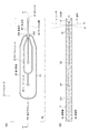
図1及び図2は、マイクロチップ型フローサイトメータとして構成された本技術に係る微小粒子分取装置1(以下「フローサイトメータ1」とも称する)の構成を説明する模式図である。また、図3及び図4は、フローサイトメータ1に搭載可能なマイクロチップ2の一例を示す。図3(A)は上面模式図、(B)は(A)中P−P断面に対応する断面模式図を示す。また、図4は、マイクロチップ2のオリフィス21の構成を模式的に説明する図であり、(A)は上面図、(B)は断面図、(C)は正面図を示す。図4(B)は、図3(A)中P−P断面に対応する。
1. 1 and 2 are schematic diagrams for explaining the configuration of a microparticle sorting apparatus 1 (hereinafter also referred to as “flow cytometer 1”) according to the present technology configured as a microchip type flow cytometer. FIG. 3 and 4 show an example of the
(1)照射検出部
フローサイトメータ1は、マイクロチップ2にレーザL1を照射する光源61と、レーザL1の照射により発生する検出対象光を検出する検出器62とを含んでなる照射検出部を備える。マイクロチップ2に対するレーザL1の照射方向(レーザL1の光軸)を図1中Z軸正方向で示す。光源61は、LD、LEDなどであってよい。
(1) Irradiation Detection Unit The flow cytometer 1 includes irradiation detection including a light source 61 that irradiates the
レーザL1は、マイクロチップ2のサンプル流路22を通流する細胞に照射される。検出器62は、細胞によるレーザL1の散乱光、及び、細胞又は細胞に標識された蛍光色素がレーザL1により励起されて生じる蛍光を検出する。図1中、サンプル流路22を通流する細胞から発生する蛍光を符合F1で示す。
The laser L 1 is applied to the cells flowing through the
照射検出部は、光源61から出射されたレーザL1を細胞に導光して集光するための集光レンズやダイクロイックミラー、バンドパスフィルター等からなる照射系を含む。また、照射検出部は、レーザL1の照射によって細胞から発生する検出対象光を集光して検出器62に導光する検出系と、によって構成される。検出系は、例えば、PMT(photo multiplier tube)や、CCDやCMOS素子等のエリア撮像素子などによって構成される。 Irradiation detection unit includes a laser L 1 emitted from the light source 61 is guided to the cell condenser lens and a dichroic mirror for condensing the illumination system comprising a band-pass filter or the like. The irradiation detection unit is configured by a detection system that collects light to be detected generated from the cells by irradiation of the laser L 1 and guides the light to the detector 62. The detection system includes, for example, a PMT (photo multiplier tube), an area imaging device such as a CCD or a CMOS device, and the like.
照射検出部の検出系により検出される検出対象光は、レーザL1の照射によって細胞から発生する光であって、例えば、前方散乱光や側方散乱光、レイリー散乱やミー散乱等の散乱光や蛍光などとすることができる。蛍光は、細胞又は細胞に標識された蛍光色素から発生するものであってよい。これらの検出対象光は電気信号に変換され、細胞の光学特性判定及び後述する光学位置の自動調整に供される。 Detected light detected by the detection system of the illumination detection unit is a light generated from the cells by irradiation of the laser L 1, for example, forward scattered light or side scattered light, Rayleigh scattering and Mie scattering or the like of the scattered light Or fluorescence. Fluorescence may be generated from cells or fluorescent dyes labeled on the cells. These detection target lights are converted into electrical signals, which are used for determining the optical characteristics of the cells and automatically adjusting the optical position described later.
(2)位置調整部
フローサイトメータ1は、照射検出部に対するマイクロチップ2の相対位置を変更する位置調整部9を備える。位置調整部9は、マイクロチップ2の位置及び/又は照射検出部の位置を、レーザL1の光軸に対する垂直平面(XY平面)上で移動させる。これにより、位置調整部9は、レーザL1の光軸に対するマイクロチップ2の位置を調整して、レーザL1がサンプル流路22内の細胞の通流位置に照射されるように最適化する。
(2) Position Adjustment Unit The flow cytometer 1 includes a
位置調整部9は、マイクロチップ2の位置、又は、光源61及び検出器62を含む照射検出部の位置の少なくとも一方を、X軸方向及びY軸方向に移動可能なものであればよい。位置調整部9は、例えばステッピングモータなどにより構成される。なお、位置調整部9は、照射検出部に対するマイクロチップ2の相対位置をZ軸方向(レーザL1の焦点方向)においても移動させるものであってよい。
The
(3)振動素子
フローサイトメータ1は、マイクロチップ2に形成されたオリフィス21に振動を印加して、オリフィス21から排出される、細胞を含むサンプル液とシース液との層流を液滴化して吐出させる振動素子3を備える。振動素子3は、例えばピエゾ素子とできる。吐出された液滴は、流体ストリームSとなって図中矢印Y軸正方向に射出される。なお、フローサイトメータ1において、マイクロチップ2は交換可能に搭載されるものである。
(3) Vibrating element The flow cytometer 1 applies vibration to the
フローサイトメータ1において、振動素子3は、マイクロチップ2と一体に構成されたものであってもよく、搭載されたマイクロチップ2と接触可能なように装置側に配設されたものであってもよい。
In the flow cytometer 1, the vibration element 3 may be configured integrally with the
(4)荷電部
オリフィス21から吐出される液滴は、荷電部41によって正又は負の電荷を付与される。一部の液滴は、電荷を付与されず、チャージなしとされていてもよい。液滴のチャージは、荷電部41と電気的に接続され、マイクロチップ2に設けられたサンプルインレット23に挿入されている電極42によって行われる。なお、電極42は、マイクロチップ2のいずれかの箇所に、流路を送液されるサンプル液又はシース液に電気的に接触するように挿入されていればよいものとする。
(4) Charging Part The droplet discharged from the
液滴への電荷の付与は、照射検出部により細胞が検出された時刻(T0)から、所定のディレイタイム(ΔT)が経過し、当該細胞がブレークオフポイントに到達した時点(T0+ΔT)で行われる。 The charge is applied to the droplets at a time (T0 + ΔT) when a predetermined delay time (ΔT) elapses from the time (T0) when the cell is detected by the irradiation detection unit and the cell reaches the break-off point. Is called.
(5)液滴検出部
また、フローサイトメータ1は、オリフィス21から吐出される液滴にレーザ光L2を照射する光源71と、レーザL2の照射により発生する検出対象光を検出する検出器72とを含んでなる液滴検出部を備える。流体ストリームSに対するレーザL2の照射方向(レーザL1の光軸)を図2中Z軸正方向で示す。光源71は、LD、LEDなどであってよい。また、検出器72は、PMT(photo multiplier tube)や、CCDやCMOS素子等のエリア撮像素子などであってよい。
(5) drop detection unit also flow cytometer 1 includes a light source 71 for irradiating a laser beam L 2 in the droplets discharged from the
レーザL2は、流体ストリームS中の液滴に照射される。検出器72は、該液滴に含まれる細胞によるレーザL2の散乱光、及び、細胞又は細胞に標識された蛍光色素がレーザL2により励起されて生じる蛍光を検出する。図2中、液滴から発生する蛍光を符合F2で示す。 The laser L 2 is irradiated to the liquid droplets in the fluid stream S. The detector 72 detects the scattered light of the laser L 2 by the cells contained in the droplets and the fluorescence generated when the fluorescent dye labeled on the cells or cells is excited by the laser L 2 . In Figure 2, shows the fluorescence generated from the droplets by reference character F 2.
光源71は、照射検出部により細胞が検出された時刻(T0)から、ディレイタイム(ΔT)を模擬する所定時間(Δt)の経過後の時点(T0+Δt)で、液滴にレーザ光L2を照射する。そして、発生する検出対象光が検出器72により電気信号に変換され、後述するディレイタイムの最適化のために利用される。 Light source 71, from the time (T0) the cells are detected by the irradiation detector, a predetermined time to simulate the delay time ([Delta] T) time after the elapse of (Δt) (T0 + Δt) , the laser beam L 2 in droplet Irradiate. The detected light to be detected is converted into an electric signal by the detector 72 and used for optimizing a delay time described later.
(6)偏向板
さらに、フローサイトメータ1は、流体ストリームSを挟んで対向して配置された一対の偏向板51,52を備える。偏向板51,52は、液滴に付与された電荷との間に作用する電気的な力によって流体ストリームS中の各液滴の進行方向を変化させる。偏向板51,52は、通常使用される電極であってよい。図1中、偏光板51,52の対向方向をX軸方向によって示す。
(6) Deflection Plate Further, the flow cytometer 1 includes a pair of deflection plates 51 and 52 arranged to face each other with the fluid stream S interposed therebetween. The deflecting plates 51 and 52 change the traveling direction of each droplet in the fluid stream S by an electric force acting between the electric charges applied to the droplets. The deflection plates 51 and 52 may be commonly used electrodes. In FIG. 1, the opposing direction of the polarizing plates 51 and 52 is indicated by the X-axis direction.
(7)回収容器
偏向板51,52の間を通過した流体ストリームは、回収容器81、回収容器82又は回収容器83のいずれかに受け入れられる。例えば、偏向板51を正、偏向板52を負に帯電させる場合、荷電部41により負にチャージされた液滴は回収容器82に、正にチャージされた液滴は回収容器83にそれぞれ回収される。また、荷電部41によりチャージされていない液滴は、偏向板51,52からの電気的な作用力を受けずに真っ直ぐ飛行し、回収容器81に回収される。フローサイトメータ1では、各液滴に含まれる細胞の特性に応じて該液滴の進行方向を制御することで、所望の特性を有する目的細胞とそれ以外の非目的細胞とを別々の回収容器に回収できる。
(7) Recovery Container The fluid stream that has passed between the deflecting plates 51 and 52 is received by any of the recovery container 81, the recovery container 82, or the recovery container 83. For example, when the deflection plate 51 is positively charged and the deflection plate 52 is negatively charged, the droplet charged negatively by the charging
回収容器81,82,83は、実験用として汎用のプラスチック製チューブあるいはガラス製チューブであってよい。これらの回収容器は、交換可能にフローサイトメータ1に配置されるものであることが好ましい。また、回収容器のうち非目的細胞を受け入れるものには、回収した液滴の排液路を接続してもよい。なお、フローサイトメータ1において、配置される回収容器の数は特に限定されないものとする。回収容器を3つよりも多く配置する場合には、各液滴が、偏向板51,52との間の電気的な作用力の有無及びその大小によっていずれか一つの回収容器に誘導され、回収されるようにする。 The collection containers 81, 82, 83 may be general-purpose plastic tubes or glass tubes for experiments. These collection containers are preferably disposed on the flow cytometer 1 in a replaceable manner. Moreover, you may connect the drainage path of the collect | recovered droplet to the thing which receives a non-target cell among collection containers. In the flow cytometer 1, the number of collection containers arranged is not particularly limited. When more than three collection containers are arranged, each droplet is guided to one of the collection containers depending on the presence / absence of the electric acting force between the deflecting plates 51 and 52 and the size thereof. To be.
(8)制御部等
フローサイトメータ1は、上述の構成に加え、通常のフローサイトメータが備える、細胞の光学特性判定のためのデータ解析部、サンプル液及びシース液を貯留するタンク部及びこれらの各構成を制御するための制御部10などを備える。
(8) Control unit, etc. In addition to the above-described configuration, the flow cytometer 1 includes a data analysis unit for determining optical characteristics of cells, a tank unit for storing a sample solution and a sheath solution, and the like, which are included in a normal flow cytometer. The
制御部10は、CPU、メモリ及びハードディスクなどを備える汎用のコンピュータによって構成でき、ハードディスク内にはOSと次に説明する制御ステップを実行するプログラムなどが格納されている。
The
(9)マイクロチップ
マイクロチップ2は、サンプル流路22が形成された基板層2a,2bが貼り合わされてなる。基板層2a,2bへのサンプル流路22の形成は、金型を用いた熱可塑性樹脂の射出成形により行うことができる。熱可塑性樹脂には、ポリカーボネート、ポリメタクリル酸メチル樹脂(PMMA)、環状ポリオレフィン、ポリエチレン、ポリスチレン、ポリプロピレン及びポリジメチルシロキサン(PDMS)などの従来マイクロチップの材料として公知のプラスチックを採用できる。
(9) Microchip The
サンプル液は、サンプルインレット23に導入され、シースインレット24に導入されるシース液と合流して、サンプル流路22を送液される。シースインレット24から導入されたシース液は、2方向に分かれて送液された後、サンプルインレット23から導入されたサンプル液との合流部において、サンプル液を2方向から挟み込むようにしてサンプル液に合流する。これにより、合流部において、シース液層流の中央にサンプル液層流が位置された3次元層流が形成される。
The sample liquid is introduced into the
符号25は、サンプル流路22に詰まりや気泡が生じた際に、サンプル流路22内に負圧を加えて流れを一時的に逆流させて詰まりや気泡を解消するための吸引流路を示す。吸引流路25の一端には、真空ポンプ等の負圧源に接続される吸引アウトレット251が形成され、他端は連通口252においてサンプル流路22に接続している。
3次元層流は、送液方向に対する垂直断面の面積が送液方向上流から下流へ次第にあるいは段階的に小さくなるように形成された絞込部261(図3参照),262(図4参照)において層流幅を絞り込まれる。その後、3次元層流は、流路の一端に設けられたオリフィス21から排出される。
In the three-dimensional laminar flow, the narrowing portions 261 (see FIG. 3) and 262 (see FIG. 4) formed so that the area of the vertical cross section with respect to the liquid feeding direction is gradually or gradually reduced from the upstream to the downstream of the liquid feeding direction. The laminar flow width is narrowed down. Thereafter, the three-dimensional laminar flow is discharged from an
サンプル流路22の絞込部261と絞込部262との間では、細胞の特性検出が行われる。照射検出部によって、サンプル流路22中を3次元層流の中心に一列に配列して送流される細胞に対してレーザL1が照射され、細胞から発生する蛍光F1及び散乱光が検出される(図3参照)。
Between the narrowing part 261 and the narrowing
サンプル流路22のオリフィス21への接続部は、直線状に形成されたストレート部27とされている。ストレート部27は、オリフィス21から流体ストリームSをY軸正方向に真っ直ぐ射出するために機能する。
A connecting portion of the
オリフィス21から排出される3次元層流は、振動素子3によりオリフィス21に印加される振動によって液滴化され、流体ストリームSとして射出される(図1参照)。オリフィス21は基板層2a,2bの端面方向に開口しており、その開口位置と基板層端面との間には切欠部211が設けられている。切欠部211は、オリフィス21の開口位置と基板端面との間の基板層2a,2bを、切欠部211の径Lがオリフィス21の開口径lよりも大きくなるように切り欠くことによって形成されている(図4(C)参照)。切欠部211の径Lは、オリフィス21から吐出される液滴の移動を阻害しないように、オリフィス21の開口径lよりも2倍以上大きく形成することが望ましい。
The three-dimensional laminar flow discharged from the
2.本技術に係る微小粒子分取装置におけるキャリブレーション方法
(A)光学位置の最適化制御
図5は、フローサイトメータ1におけるマイクロチップ2の光学位置の最適化のための制御ステップを説明するフローチャートである。制御ステップは、「キャリブレーションビーズ送液ステップS1」、「信号取得ステップS2」、「エリア平均値最大位置判定ステップS3」、「エリア平均値最大位置移動ステップS4」、「信号取得ステップS5」、「積算値最大位置判定ステップS6」、「変動係数判定ステップS7」及び「位置最適化ステップS8」の手順を含む。以下、各手順について説明する。
2. FIG. 5 is a flowchart for explaining the control steps for optimizing the optical position of the
(1)キャリブレーションビーズ送液ステップS1
ユーザにより分析の開始信号が入力されると、制御部10は位置調整部9へ移動信号を出力し、位置調整部9が照射検出部に対するマイクロチップ2の相対位置を予め設定された初期位置(図6、原点Oを参照)に移動させる。相対位置が原点Oにあるとき、照射検出部から出射されたレーザL1はマイクロチップ2上の原点Oに照射される。相対位置の変更は、マイクロチップ2の位置、又は、光源61及び検出器62を含む照射検出部の位置の少なくとも一方を、X軸方向及びY軸方向に移動することによって行い得るが、以下ではマイクロチップ2の位置を移動する場合を例に説明する。
(1) Calibration beads feeding step S 1
When the analysis start signal is input by the user, the
次に、制御部10は、サンプル液及びシース液を貯留するタンク部のポンプを駆動して、マイクロチップ2のサンプルインレット23及びシースインレット24へのサンプル液及びシース液の送液を開始する。サンプル液には、サイズ及び蛍光強度が異なる2種以上のキャリブレーション用の粒子(ビーズ)が含まれる。さらに、制御部10は、振動素子3によるオリフィス21への振動印加を開始する。これにより、オリフィス21から射出されるサンプル液及びシース液の3次元層流が液滴化して吐出され、流体ストリームSが発生する。
Next, the
キャリブレーションビーズは、蛍光色素を含む樹脂組成物を粒子形状に成形したもの又は粒子形状に成形された樹脂の表面に蛍光色素を固着させたものなどを用いることができる。蛍光色素には、PB,FITC,PE,PE−TR,APCCHなどの汎用の色素を用いればよい。一般に、サイズの大きいビーズほど蛍光強度が高くなるが、サイズ及び蛍光強度のばらつきが大きくなる。逆に、サイズの小さいビーズほど蛍光強度は低くなるが、サイズ及び蛍光強度のばらつきも小さくなる。 As the calibration beads, a resin composition containing a fluorescent dye formed into a particle shape, or a resin dye fixed on the surface of a resin formed into a particle shape can be used. A general-purpose dye such as PB, FITC, PE, PE-TR, or APCCH may be used as the fluorescent dye. In general, the larger the size of the beads, the higher the fluorescence intensity, but the variation in size and fluorescence intensity increases. Conversely, the smaller the size of the beads, the lower the fluorescence intensity, but the smaller the size and fluorescence intensity variations.
キャリブレーションビーズは、サイズが小さく蛍光強度が低いビーズAと、サイズが大きく蛍光強度が高いビーズBと、の2種を含むことが好ましい。また、ビーズBのポピュレーションが、ビーズAのポピュレーションよりも大きいことが好ましい。 The calibration beads preferably include two types of beads A, which are small in size and low in fluorescence intensity, and beads B which are large in size and high in fluorescence intensity. Also, the population of beads B is preferably larger than the population of beads A.
ビーズAとしては、例えば粒径が2〜4μmであり、流体(サンプル液)中の濃度が5.0×10⁵/ml程度で、蛍光強度のばらつき(変動係数)が1.5%以下のものを使用できる。また、ビーズBとしては、例えば粒径が8〜12μmであり、流体中の濃度が5.0×106/ml程度で、蛍光強度のばらつき(変動係数)が2.5%以下のものを使用できる。 As the beads A, for example, the particle diameter is 2 to 4 μm, the concentration in the fluid (sample liquid) is about 5.0 × 10 5 / ml, and the variation (coefficient of variation) in fluorescence intensity is 1.5% or less. Things can be used. Further, as the beads B, for example, those having a particle diameter of 8 to 12 μm, a concentration in the fluid of about 5.0 × 10 6 / ml, and a variation (coefficient of variation) in fluorescence intensity of 2.5% or less. Can be used.
キャリブレーションビーズには、ビーズAとビーズBとの中間のサイズ及び蛍光強度を有するビーズが含まれていてもよい。以下では、ビーズAとビーズBの2種のビーズが混合されたキャリブレーションビーズを用いる場合を例に説明する。 The calibration beads may include beads having an intermediate size and fluorescence intensity between the beads A and B. Hereinafter, a case where calibration beads in which two kinds of beads A and B are mixed is used will be described as an example.
サンプル液及びシース液の送液開始後、制御部10は、位置調整部9へ移動信号を出力し、位置調整部9がマイクロチップ2の位置を原点Oから基準点D0に移動させる(図6矢印参照)。照射検出部に対するマイクロチップ2の相対位置が基準点D0にあるとき、照射検出部から出射されたレーザL1はマイクロチップ2上の基準点D0に照射される。
Sample solution and after liquid feed initiation of the sheath liquid, the
基準点D0は、マイクロチップ2の細胞の特性検出が行われるべき位置(すなわち、以下に説明するステップにより決定される最適位置)の近傍に予め設定される。より具体的には、基準点D0は、サンプル流路22の絞込部261と絞込部262との間(図3及び図4参照)の近傍とされる。
Reference point D 0, the position should cell characteristics detection is performed in the microchip 2 (i.e., the optimum position determined by the steps described below) is pre-set in the vicinity of. More specifically, the reference point D 0 is set in the vicinity between the narrowing part 261 and the narrowing
(2)信号取得ステップS2(第一の信号取得ステップ)
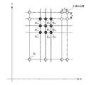
本ステップS2では、照射検出部により、基準点D0を含むマイクロチップ2上の複数の位置から発生する蛍光又は散乱光(以下、単に「蛍光」と称する)の検出が行われる。本ステップS2において、蛍光の検出が行われるマイクロチップ2上の位置を図6中符号Dにより示す。図では、基準点D0を含めて24箇所の検出位置Dを設定し、X軸方向に8列、Y軸方向に3列に配列した検出位置Dからの蛍光を検出する場合を例に示した。
(2) Signal acquisition step S 2 (first signal acquisition step)
In this step S 2, the irradiation detection unit, fluorescence or scattered light generated from a plurality of locations on the
検出位置Dが設定される領域にはサンプル流路22が含まれるようにされ、この限りにおいて検出位置Dの数及び配列態様は特に限定されず任意に設定される。検出位置Dは、図に示すようにX軸方向及びY軸方向に格子状に配列されることが好ましい。この場合、検出位置DのX軸方向及びY軸方向の配列間隔W及びHは、サンプル流路22の流路幅(流路径)とX軸方向及びY軸方向における検出位置Dの配列数M1,N1に応じて適宜設定され得る。サンプル流路22の流路幅が70〜100μmであり、配列数M1が8,N1が3である場合、配列間隔W及びHは、例えばそれぞれ25、75μmに設定される。
The region where the detection position D is set includes the
蛍光の検出は、一つの検出位置Dについて一定時間行われる。一定時間に検出された蛍光は積算されて電気信号に変換され制御部10に出力される。蛍光の検出は、レーザL1をX軸方向及びY軸方向に走査して各検出位置Dに順次照射して、発生する蛍光を検出することによって行い得る。あるいは、レーザL1の照射により各検出位置Dから蛍光をエリア撮像素子によって一括検出してもよい。
The detection of fluorescence is performed for one detection position D for a certain period of time. Fluorescence detected in a certain time is integrated and converted into an electrical signal and output to the
(3)エリア平均値最大位置判定ステップS3
本ステップS3では、制御部10は、各検出位置Dについて検出強度の積算値のエリア平均値を算出し、エリア平均値がより大きくなる検出位置D、好ましくは最大値となる検出位置Dを自動判定する。
(3) Area average value maximum position determination step S 3
In this step S 3, the
「エリア平均値」とは、一つの検出位置Dと、それから所定の距離範囲内にある複数の検出位置Dと、で得られた検出強度の積算値の平均を意味する。図6では、エリア平均値を、一つの検出位置D1と、検出位置D1からX軸方向に2W、Y軸方向に2Hの距離範囲内にある検出位置D2〜D9と、で得られた検出強度の積算値の平均とする場合を示した。 “Area average value” means an average of integrated values of detection intensities obtained at one detection position D and a plurality of detection positions D within a predetermined distance range therefrom. In FIG. 6, the area average value is obtained at one detection position D 1 and detection positions D 2 to D 9 within a distance range of 2 W in the X-axis direction and 2 H in the Y-axis direction from the detection position D 1. The case where it was set as the average of the integrated value of the obtained detection intensity was shown.
一つの検出位置Dからどれくらいの距離範囲内をエリア平均値として設定するかは、サンプル流路22の流路幅(流路径)、配列間隔W及びHに応じて適宜決定され得るものとする。
It is assumed that how much distance range from one detection position D is set as the area average value can be appropriately determined according to the channel width (channel diameter) of the
制御部10は、各検出位置Dについて算出されたエリア平均値を比較し、エリア平均値がより大きくなる検出位置D、好ましくは最大値となる検出位置D、を決定する。ここでは、検出位置D1においてエリア平均値が最大値となるものとして説明する。
The
エリア平均値の算出は、各検出位置Dについて一定時間内に検出された蛍光のうち、キャリブレーションビーズから発生する蛍光に基づいて行われる。各検出位置Dにおいて一定時間内に検出信号のヒストグラムを図7に示す。ビーズBは、ビーズAに比して蛍光強度が高く、蛍光強度のばらつきが大きい。エリア平均値は、ビーズA及びビーズBから発生する蛍光の検出強度の和として算出される。 The area average value is calculated based on the fluorescence generated from the calibration beads among the fluorescence detected for each detection position D within a predetermined time. FIG. 7 shows a histogram of detection signals within a predetermined time at each detection position D. The bead B has a higher fluorescence intensity than the bead A and has a large variation in fluorescence intensity. The area average value is calculated as the sum of the detection intensities of the fluorescence generated from the beads A and B.
蛍光はキャリブレーションビーズが通流されるサンプル流路22で強く発生するため、エリア平均値が最大値となる検出位置D1〜D9を結んで形成される領域R1は、サンプル流路22が位置する領域とみなし得る。なお、「エリア平均値」に替えて、各検出位置Dで得られた検出強度そのもの(ピーク強度)、又は該検出強度の平均値あるいは積算値を用いてもよい。ピーク強度、平均値又は積算値が最大値となる検出位置Dは、サンプル流路22に近接する点とみなし得る。
Since fluorescence is strongly generated in the
(4)エリア平均値最大位置移動ステップS4
エリア平均値が最大値となる検出位置D1が特定されると、制御部10は、位置調整部9へ移動信号を出力し、位置調整部9がマイクロチップ2の位置を基準点D0から検出位置D1に移動させる(図8矢印参照)。
(4) Area average value maximum position moving step S 4
If the area average value detection position D 1 which is a maximum value is specified, the
(5)信号取得ステップS5(第一の信号取得ステップ)
本ステップS5では、照射検出部により、エリア平均値が最大値となる領域R1内の複数の位置から発生する蛍光の検出が行われる。本ステップS5における蛍光の検出位置Dを図8の拡大図中に示す。図では、エリア平均値が最大値となる検出位置D1を含めてX軸方向にM2列、Y軸方向にN2列配列した(M2×N2)の検出位置Dから蛍光を検出する場合を例に示した。
(5) Signal acquisition step S 5 (first signal acquisition step)
In this step S 5, the irradiation detecting section, area average value detection of fluorescence emitted from a plurality of locations in the region R 1 to be the maximum value is performed. The detection position D of fluorescence in this step S 5 shown in enlarged view of FIG. In the figure, fluorescence is detected from (M 2 × N 2 ) detection positions D in which M 2 rows are arranged in the X-axis direction and N 2 rows are arranged in the Y-axis direction including the detection position D 1 where the area average value is the maximum value. The case of doing is shown as an example.
検出位置DのX軸方向及びY軸方向の配列間隔w及びhは、サンプル流路22の流路幅(流路径)とX軸方向及びY軸方向における配列数M2及びN2に応じて適宜設定され得る。配列数M2,N2は、例えばそれぞれ11、7個とされる。列間隔w及びhは、例えばそれぞれ5、25μmに設定される。なお、本ステップS5においても、検出位置Dの数及び配列態様は特に限定されないものとする。なお、「エリア平均値」に替えて、各検出位置Dで得られたピーク強度、平均値又は積算値を用いる場合、これらの値が最大値となる検出位置Dを含む領域内に適当数の検出位置Dを設定する。
The arrangement intervals w and h of the detection position D in the X-axis direction and the Y-axis direction depend on the flow path width (flow path diameter) of the
蛍光の検出は、一つの検出位置Dについて一定時間行われる。一定時間に検出された蛍光は電気信号に変換され制御部10に出力される。蛍光の検出は、レーザL1をX軸方向及びY軸方向に走査して各検出位置Dに順次走査し、発生する蛍光を検出する。あるいは、エリア撮像素子によって、レーザL1の照射により各検出位置Dから蛍光を一括検出してもよい。
The detection of fluorescence is performed for one detection position D for a certain period of time. The fluorescence detected for a certain time is converted into an electric signal and output to the
(6)積算値最大位置判定ステップS6
本ステップS6では、制御部10は、各検出位置Dについて、検出強度の積算値又は平均値のどちらか一方又は両方と、それらの変動係数(CV値)とを算出する。以下では、検出強度の積算値とそのCV値とを用いた処理を例に説明する。
(6) Integrated value maximum position determination step S 6
In this step S 6, the
制御部10は、各検出位置Dについて算出された検出強度の積算値を比較し、積算値がより大きくなる検出位置D、好ましくは最大値となる検出位置D(第一の最適位置)、を決定する。ここでは、検出位置D11において積算値が最大値となるものとして説明する(図8参照)。
The
検出強度の積算値及び変動係数の算出は、各検出位置Dについて一定時間内に検出された蛍光のうち、ビーズAから発生する蛍光に基づいて行われる(図7のヒストグラムを参照)。ビーズAから発生する蛍光とビーズBから発生する蛍光との区別は、蛍光波長の違いによって区別してビーズAの蛍光波長に一致する蛍光のみを検出すればよい。あるいは、サイズの違いによってビーズにゲーティングをかけて、選択されたサイズの範囲(ゲート)内のビーズから発生する蛍光のみを検出することで、ビーズAから発生する蛍光とビーズBから発生する蛍光とを区別することもできる。 Calculation of the integrated value of the detection intensity and the coefficient of variation is performed based on the fluorescence generated from the beads A among the fluorescence detected within a predetermined time for each detection position D (see the histogram in FIG. 7). The fluorescence generated from the bead A and the fluorescence generated from the bead B may be distinguished by the difference in the fluorescence wavelength, and only the fluorescence that matches the fluorescence wavelength of the bead A may be detected. Alternatively, the fluorescence generated from the beads A and the fluorescence generated from the beads B can be detected by gating the beads according to the difference in size and detecting only the fluorescence generated from the beads within the selected size range (gate). Can also be distinguished.
(7)変動係数判定ステップS7
次に、制御部10は、積算値が最大値となる検出位置D11と隣接する検出位置D12〜D19との間でCV値を比較し、検出位置D11に比してより小さいCV値を与える検出位置D(第二の最適位置)の存在の有無を自動判定する(図9参照)。
(7) variation coefficient determining step S 7
Next, the
(8)位置最適化ステップS8
ステップS7において、積算値が最大値となる検出位置D11に比してより小さいCV値を与える検出位置Dが、検出位置D11と隣接する検出位置D12〜D19のいずれにもみつからなった場合、制御部10は、マイクロチップ2の位置を検出位置D1から検出位置D11に移動させる。このとき、積算値が最大値となる検出位置(第一の最適位置)とCV値が最小値となる検出位置(第二の最適位置)はいずれも検出位置D11で一致している。
(8) Position optimization step S 8
In step S 7 , a detection position D that gives a smaller CV value than the detection position D 11 where the integrated value is the maximum value is found in any of the detection positions D 12 to D 19 adjacent to the detection position D 11. when it becomes, the
また、ステップS7において、検出位置D12〜D19のいずれかに検出位置D11に比してより小さいCV値を与える検出位置Dがみつかった場合、制御部10は、マイクロチップ2の位置を検出位置D1から当該検出位置D(例えば検出位置D18)に移動させる。このとき、積算値が最大値となる検出位置(第一の最適位置)とCV値が最小値となる検出位置(第二の最適位置)は不一致である。
In step S 7 , if a detection position D that gives a smaller CV value than any of the detection positions D 11 is found in any of the detection positions D 12 to D 19 , the
積算値が最大値となる検出位置D11は、蛍光が最も強く発生する位置であり、サンプル流路22のキャリブレーションビーズの通流位置とみなすことができる。すなわち、照射検出部に対するマイクロチップ2の相対位置が検出位置D11にあるとき、照射検出部から出射されたレーザL1はサンプル流路22のキャリブレーションビーズの通流位置に照射されることとなる。
Detecting position D 11 of the integrated value becomes the maximum value, the fluorescence is most strongly generated position, can be regarded as a flowing position of the calibration
例外的に、積算値が最大値となる検出位置D11が、サンプル流路22のキャリブレーションビーズの通流位置ではないにもかからず、蛍光強度の積算値が最大値となる場合がある。例えば、検出位置D11が、マイクロ流路22の流路壁に一致する場合には、蛍光の反射や散乱などによって異常に高い蛍光強度が散発的に検出されてしまう場合がある。この場合、当該位置において検出される蛍光強度にばらつきが生じ、蛍光強度の積算値のCV値が大きくなる。
Exceptionally, the detection position D 11 the integrated value is the maximum value, in less than not the flowing position of the calibration beads of the
検出位置D11がマイクロ流路22の流路壁に一致する場合などでは、検出位置D11と隣接する検出位置のうちより小さいCV値を与える検出位置D18が、サンプル流路22のキャリブレーションビーズの通流位置とみなすことができる。すなわち、照射検出部に対するマイクロチップ2の相対位置が検出位置D18にあるとき、照射検出部から出射されたレーザL1はサンプル流路22のキャリブレーションビーズの通流位置に照射されることとなる。
When the detection position D 11 coincides with the flow path wall of the
以上のように、フローサイトメータ1では、レーザL1の照射によりマイクロチップ2から発生する蛍光の検出強度の積算値あるいは平均値がより大きくなる位置、又はCV値がより小さくなる位置に、レーザL1に対するマイクロチップ2の相対位置を設定する。これにより、フローサイトメータ1では、マイクロチップ2のサンプル流路22の細胞の通流位置と、レーザL1の光軸と、を自動で高精度に位置決めし、簡便に高精度な測定を行うことが可能とされている。
As described above, in the flow cytometer 1, the laser is positioned at a position where the integrated value or average value of the detection intensity of fluorescence generated from the
また、フローサイトメータ1では、蛍光検出強度の積算値のエリア平均値がより大きくなる位置を特定する粗調整(ステップS2・S3)と、エリア平均値がより大きくなる領域内において積算値あるいは平均値がより大きくなる位置、又はCV値がより小さくなる位置を特定する微調整(ステップS5〜S7)との2段階の手順によって、マイクロチップ2の光学位置を最適化している。これにより、マイクロチップ2の光学位置の最適化を小さい処理負荷で迅速に行うことが可能とされている。
Further, in the flow cytometer 1, rough adjustment (steps S 2 and S 3 ) for specifying a position where the area average value of the integrated value of the fluorescence detection intensity becomes larger, and the integrated value in a region where the area average value becomes larger. or a position where the average value becomes larger, or by two-step procedure with the fine adjustment (step S 5 to S 7) the CV value to identify a more reduced position, and optimizes the optical position of the
さらに、フローサイトメータ1では、粗調整(ステップS2・S3)を、全種のキャリブレーションビーズ(ここではビーズA及びビーズB)から発生する光の検出強度に基づいて行い、微調整(ステップS5〜S7)は、サイズが小さい種のビーズ(ビーズA)のみから発生する光の検出強度に基づいて行っている。これにより、粗調整では、強い検出信号を用いて制御を行うことができ、微調整では、サンプル流路22の細胞の通流位置とレーザL1の光軸との位置合わせを高精度に行うことができる。ここでは、流路をマイクロチップに形成したマイクロチップ型フローサイトメータを例に説明したが、フローセルに流路が形成されたフローセル型フローサイトメータにおいても、同様の効果を得ることができる。
Further, in the flow cytometer 1, coarse adjustment (steps S 2 and S 3 ) is performed based on the detection intensity of light generated from all types of calibration beads (here, beads A and beads B), and fine adjustment ( Steps S 5 to S 7 ) are performed based on the detection intensity of light generated only from a small-sized bead (bead A). Thus, the coarse adjustment can be controlled by using a strong detection signal, the fine adjustment is carried out through flow position of the cells of the
(B)ディレイタイムの最適化制御
図10は、フローサイトメータ1におけるディレイタイムの最適化のための制御ステップを説明するフローチャートである。制御ステップは、「キャリブレーションビーズ送液ステップS11」、「信号取得ステップS12」、「最適経過時間探索ステップS13」及び「ディレイタイム設定ステップS14」の手順を含む。以下、各手順について説明する。
(B) Delay Time Optimization Control FIG. 10 is a flowchart illustrating control steps for delay time optimization in the flow cytometer 1. The control step includes a procedure of “calibration bead feeding step S 11 ”, “signal acquisition step S 12 ”, “optimum elapsed time search step S 13 ”, and “delay time setting step S 14 ”. Hereinafter, each procedure will be described.
(1)キャリブレーションビーズ送液ステップS11
ユーザにより分析の開始信号が入力されると、制御部10は、サンプル液及びシース液を貯留するタンク部のポンプを駆動して、マイクロチップ2のサンプルインレット23及びシースインレット24へのサンプル液及びシース液の送液を開始する。サンプル液には、上述のキャリブレーションビーズが含まれる。さらに、制御部10は、振動素子3によるオリフィス21への振動印加を開始する。これにより、オリフィス21から射出されるサンプル液及びシース液の3次元層流が液滴化して吐出され、流体ストリームSが発生する。
(1) Calibration beads liquid feed step S 11
When the analysis start signal is input by the user, the
(2)信号取得ステップS12(第二の信号取得ステップ)
本ステップS12では、オリフィス21から吐出される液滴に、光源71からレーザL2を照射して、液滴から発生する蛍光の検出が行われる。レーザL2は、照射検出部によりキャリブレーションビーズが検出された時刻(T0)から所定時間(Δt)の経過後に光源71から液滴に照射され、液滴から発生する蛍光が検出器72により検出される。
(2) Signal acquisition step S 12 (second signal acquisition step)
In this step S 12, the droplets discharged from the
制御部10は、時刻T0から異なる時間の経過後に光源71からレーザL2を出射させる。具体的には、制御部10は、時刻(T0+Δt1)、(T0+Δt2)、・・・(T0+ΔtN)において光源71からレーザL2を出射させる。ここで、Nは3以上の整数を示す。各時刻において、検出器72により検出された蛍光の検出強度は、制御部10に出力されて保持される。
時刻(T0+ΔtN)における検出強度は、キャリブレーションビーズが照射検出部により検出された時刻T0から時間ΔtN経過後に、レーザL2をオリフィス21から吐出される液滴に照射して得られる検出強度を、例えばM個のビーズについて積算した値とされる。
The detection intensity at the time (T0 + Δt N ) is the detection intensity obtained by irradiating the droplet discharged from the
(3)最適経過時間探索ステップS13
本ステップS13では、制御部10は、液滴から発生する蛍光の検出強度の積算値がより大きくなる(好ましくは最大値となる)経過時間ΔtSを決定する。具体的には、時刻(T0+Δt1)〜(T0+ΔtN)において取得された検出強度の積算値を比較し、積算値がより大きくなる経過時間ΔtSを特定する。
(3) Optimal elapsed time search step S 13
In this step S 13, the
経過時間ΔtSの決定は、液滴に含まれるビーズA及びビーズBから発生する蛍光の検出強度の和に基づいて行われる。より好ましくは、経過時間ΔtSの決定は、ビーズBから発生する蛍光の検出強度に基づいて行われる(図7のヒストグラムを参照)。ビーズAから発生する蛍光とビーズBから発生する蛍光との区別は、蛍光波長の違いによって区別してビーズBの蛍光波長に一致する蛍光のみを検出すればよい。あるいは、サイズの違いによってビーズにゲーティングをかけて、選択されたサイズの範囲(ゲート)内のビーズから発生する蛍光のみを検出することで、ビーズBから発生する蛍光とビーズBから発生する蛍光とを区別することもできる。 The elapsed time Δt S is determined based on the sum of detection intensities of fluorescence generated from the beads A and B contained in the droplet. More preferably, the elapsed time Δt S is determined based on the detection intensity of the fluorescence generated from the beads B (see the histogram of FIG. 7). The fluorescence generated from the bead A and the fluorescence generated from the bead B may be distinguished from each other according to the difference in the fluorescence wavelength, and only the fluorescence that matches the fluorescence wavelength of the bead B may be detected. Alternatively, the fluorescence generated from the beads B and the fluorescence generated from the beads B are detected by gating the beads according to the difference in size and detecting only the fluorescence generated from the beads within the selected size range (gate). Can also be distinguished.
(4)ディレイタイム設定ステップS14
本ステップS14では、最適経過時間探索ステップS13で特定された経過時間Δtsからディレイタイム(ΔT)の算出が行われる。経過時間Δtsは、時刻T0において照射検出部により検出されたキャリブレーションビーズが光源71から出射されるレーザL2の照射位置を通過するまでの時間とみなすことができる。従って、経過時間Δtsに基づけば、照射検出部により検出されたキャリブレーションビーズがブレークオフポイントに到達するまでの時間であるディレイタイム(ΔT)を算出できる。制御部10は、算出されたディレイタイム(ΔT)を荷電部41に設定し、最適なディレイタイムにおいて液滴に電荷が付与されるようにする。
(4) the delay time setting step S 14
In this step S 14, calculated from the elapsed time Delta] t s specified by the optimum elapsed time search step S 13 the delay time ([Delta] T) is performed. Age Delta] t s can be calibrated beads detected by the irradiation detector at time T0 is regarded as the time to pass through the irradiation position of the laser L 2 emitted from the light source 71. Therefore, based on the elapsed time Delta] t s, calibration beads detected by irradiation detection unit can calculate the delay time ([Delta] T) is the time to reach the break-off point. The
以上のように、フローサイトメータ1では、全種のキャリブレーションビーズ(ここではビーズA及びビーズB)から発生する光、あるいは蛍光強度が高い種のビーズ(ビーズB)のみから発生する光の検出強度に基づいて、ディレイタイムの最適化を行っている。これにより、強い検出信号を用いてディレイタイムの最適化制御を行うことができる。キャリブレーションビーズ中のサイズが大きく蛍光強度が高いビーズ(ビーズB)のポピュレーションを、サイズが小さく蛍光強度が低いビーズ(ビーズA)のポピュレーションよりも大きくしておくことで、より強い検出信号を用いたディレイタイムの最適化制御が可能となる。 As described above, the flow cytometer 1 detects light generated from all types of calibration beads (here, beads A and B), or light generated only from types of beads having high fluorescence intensity (beads B). The delay time is optimized based on the strength. Thereby, optimization control of delay time can be performed using a strong detection signal. A stronger detection signal by keeping the population of beads (bead B) with larger size and higher fluorescence intensity in the calibration beads larger than the population of beads (bead A) with smaller size and lower fluorescence intensity This makes it possible to optimize the delay time using the.
また、フローサイトメータ1では、上述した光学位置の最適化制御とディレイタイムの最適化制御とを、キャリブレーションビーズを入れ替えることなく行うことができる。従来、レーザの光軸に対するマイクロチップの位置調整はサイズの小さいビーズを用いて行い、別個に、蛍光強度の高いビーズを用いてディレイタイムの最適化を行う必要があった。これに対して、フローサイトメータ1では、サイズ及び蛍光強度が異なる2種以上のビーズを含むキャリブレーションビーズを用いてマイクロチップの光学位置調整とディレイタイムの最適化とをキャリブレーションビーズを入れ替えることなく簡便に行うことが可能とされている。 The flow cytometer 1 can perform the above-described optical position optimization control and delay time optimization control without replacing calibration beads. Conventionally, the position adjustment of the microchip with respect to the optical axis of the laser has been performed using beads with a small size, and it has been necessary to optimize the delay time separately using beads with high fluorescence intensity. On the other hand, in the flow cytometer 1, the calibration beads are exchanged for the optical position adjustment of the microchip and the optimization of the delay time by using calibration beads including two or more kinds of beads having different sizes and fluorescence intensities. It is possible to carry out easily without any problem.
本技術に係る微小粒子分取装置におけるキャリブレーション方法は以下のような構成もとることができる。
(1)マイクロチップ又はフローセルに形成された流路にサイズ及び蛍光強度が異なる2種以上のキャリブレーション粒子を含む流体を通流する送液手順と、レーザ照射により前記マイクロチップ又は前記フローセルから発生する光を前記マイクロチップ又は前記フローセル上の複数の位置から検出する第一の信号取得手順と、全種の前記キャリブレーション粒子から発生する光の検出強度の積算値のエリア平均値がより大きくなる位置を特定する手順と、を含む微小粒子分取装置におけるキャリブレーション方法。
(2)前記検出強度として、全種の前記キャリブレーション粒子から発生する光の検出強度の積算値のエリア平均値を用いる上記(1)記載のキャリブレーション方法。
(3)前記エリア平均値がより大きくなるエリア内において、前記キャリブレーション粒子のうちサイズが小さい種の粒子から発生する光の検出強度がより大きくなる第一の最適位置を特定する手順を含む上記(2)記載のキャリブレーション方法。
(4)前記第一の最適位置は、前記キャリブレーション粒子のうちサイズが小さい種の粒子から発生する光の検出強度の積算値又は平均値がより大きくなる位置である上記(3)記載のキャリブレーション方法。
(5)前記エリア平均値がより大きくなるエリア内において、前記キャリブレーション粒子のうちサイズが小さい種の粒子から発生する光の検出強度の積算値又は平均値の変動係数がより小さくなる第二の最適位置を特定する手順を含む上記(2)〜(4)のいずれかに記載のキャリブレーション方法。
(6)前記レーザに対する前記マイクロチップの相対位置を、前記第一の最適位置又は前記第二の最適位置に設定する手順を含む上記(5)記載のキャリブレーション方法。
(7)前記第一の最適位置と前記第二の最適位置が異なる場合に、前記相対位置を前記第二の最適位置に設定する上記(6)記載のキャリブレーション方法。
(8)前記流路の一端に形成されたオリフィスから吐出される液滴に対して、前記流路を通流する前記キャリブレーション粒子から発生する光の検出時刻から所定時間経過後にレーザを照射し、前記液滴から発生する光を検出する第二の信号取得手順と、
全種の前記キャリブレーション粒子から発生する光の検出強度の積算値、あるいは前記キャリブレーション粒子のうちサイズが大きい種の粒子から発生する光の検出強度の積算値、がより大きくなる経過時間を特定する手順と、を含む上記(1)〜(7)のいずれかに記載のキャリブレーション方法。
(9)前記経過時間をディレイタイムとして設定する手順を含む上記(8)記載のキャリブレーション方法。
(10)前記キャリブレーション粒子として、サイズが小さく蛍光強度が低い粒子と、サイズが大きく蛍光強度が高い粒子と、の2種を用いる上記(1)〜(9)のいずれかに記載のキャリブレーション方法。
(11)前記キャリブレーション粒子中のサイズが大きく蛍光強度が高い粒子のポピュレーションが、サイズが小さく蛍光強度が低い粒子のポピュレーションよりも大きい上記(10)記載のキャリブレーション方法。
The calibration method in the fine particle sorting apparatus according to the present technology can be configured as follows.
(1) A liquid feeding procedure for flowing a fluid containing two or more kinds of calibration particles having different sizes and fluorescence intensities through a flow path formed in the microchip or flow cell, and generated from the microchip or the flow cell by laser irradiation. The area average value of the first signal acquisition procedure for detecting the light to be detected from a plurality of positions on the microchip or the flow cell and the integrated value of the detection intensity of the light generated from all types of the calibration particles becomes larger. And a calibration method in a microparticle sorting apparatus, including a procedure for specifying a position.
(2) The calibration method according to (1), wherein an area average value of integrated values of detection intensities of light generated from all types of the calibration particles is used as the detection intensity.
(3) In the area where the area average value is larger, the method includes the step of identifying a first optimum position where the detection intensity of light generated from a small-sized seed particle among the calibration particles is larger. (2) The calibration method according to the description.
(4) The calibration according to (3), wherein the first optimum position is a position at which an integrated value or an average value of detected intensities of light generated from small-sized particles of the calibration particles is larger. Method.
(5) In an area where the area average value is larger, a second integrated value or a variation coefficient of the average value of the detected intensity of light generated from a small-sized particle of the calibration particles is smaller. The calibration method according to any one of (2) to (4), including a procedure for specifying an optimum position.
(6) The calibration method according to (5), including a procedure for setting a relative position of the microchip to the laser at the first optimum position or the second optimum position.
(7) The calibration method according to (6), wherein the relative position is set to the second optimum position when the first optimum position is different from the second optimum position.
(8) A laser beam is emitted to a droplet discharged from an orifice formed at one end of the flow path after a predetermined time has elapsed from the detection time of light generated from the calibration particles flowing through the flow path. A second signal acquisition procedure for detecting light generated from the droplet;
Identifies the elapsed time when the integrated value of the detection intensity of light generated from all types of the calibration particles or the integrated value of the detection intensity of light generated from particles of a large size among the calibration particles becomes larger A calibration method according to any one of the above (1) to (7).
(9) The calibration method according to (8), including a procedure for setting the elapsed time as a delay time.
(10) The calibration according to any one of the above (1) to (9), wherein two types of particles are used, which are particles having a small size and a low fluorescence intensity, and particles having a large size and a high fluorescence intensity. Method.
(11) The calibration method according to (10), wherein a population of particles having a large size and a high fluorescence intensity in the calibration particles is larger than a population of particles having a small size and a low fluorescence intensity.
また、本技術に係る微小粒子分取装置は以下のような構成をとることもできる。
(1)サイズ及び蛍光強度が異なる2種以上のキャリブレーション粒子を含む流体が流路に通流されたマイクロチップ又はフローセルにレーザを照射して発生する光を検出する照射検出部と、該照射検出部に対する前記マイクロチップ又は前記フローセルの相対位置を変更する位置調整部と、全種の前記キャリブレーション粒子から発生する光の検出強度がより大きくなる位置への移動信号を前記位置調整部に出力する制御部と、を備える微小粒子分取装置。
(2)前記検出強度が、全種の前記キャリブレーション粒子から発生する光の検出強度の積算値のエリア平均値である上記(1)記載の微小粒子分取装置。
(3)前記制御部は、前記エリア平均値がより大きくなるエリア内において、前記キャリブレーション粒子のうちサイズが小さい種の粒子から発生する光の検出強度がより大きくなる第一の最適位置への移動信号を前記位置調整部に出力する上記(2)記載の微小粒子分取装置。
(4)前記制御部は、前記エリア平均値がより大きくなるエリア内において、前記キャリブレーション粒子のうちサイズが小さい種の粒子から発生する光の検出強度の積算値又は平均値の変動係数がより小さくなる第二の最適位置への移動信号を前記位置調整部に出力する上記(2)又は(3)記載の微小粒子分取装置。
(5)前記制御部は、前記第一の最適位置と前記第二の最適位置が異なる場合に、前記第二の最適位置への移動信号を前記位置調整部に出力する上記(4)記載の微小粒子分取装置。
(6)前記流路の一端に形成されたオリフィスから吐出される液滴に対して、前記照射検出部による前記キャリブレーション粒子から発生する光の検出時刻から所定時間経過後にレーザを照射する光源と、前記液滴から発生する光を検出する検出部と、を備え、前記制御部は、全種の前記キャリブレーション粒子から発生する光の検出強度の積算値、あるいは前記キャリブレーション粒子のうちサイズが大きい種の粒子から発生する光の検出強度の積算値、がより大きくなる経過時間をディレイタイムとして設定する上記(1)〜(5)のいずれかに記載の微小粒子分取装置。
In addition, the fine particle sorting apparatus according to the present technology may have the following configuration.
(1) An irradiation detection unit that detects light generated by irradiating a laser to a microchip or a flow cell in which fluids containing two or more kinds of calibration particles having different sizes and fluorescence intensities are passed through the flow path, and the irradiation A position adjustment unit that changes the relative position of the microchip or the flow cell with respect to the detection unit, and a movement signal to a position where the detection intensity of light generated from all types of calibration particles becomes larger is output to the position adjustment unit. A fine particle sorting device comprising a control unit.
(2) The fine particle sorting apparatus according to (1), wherein the detection intensity is an area average value of integrated values of detection intensity of light generated from all types of the calibration particles.
(3) In the area where the area average value is larger, the control unit is directed to the first optimum position where the detection intensity of light generated from the small-sized seed particle among the calibration particles is larger. The fine particle sorting apparatus according to (2), wherein a movement signal is output to the position adjustment unit.
(4) In the area where the area average value is larger, the control unit has an integrated value or a coefficient of variation of the average value of the detected intensity of light generated from a small-sized particle of the calibration particles. The fine particle sorting device according to (2) or (3) , wherein a movement signal to a second optimum position that decreases is output to the position adjustment unit.
(5) The control unit according to (4), wherein the control unit outputs a movement signal to the second optimum position to the position adjustment unit when the first optimum position and the second optimum position are different. Fine particle sorting device.
(6) a light source that irradiates a droplet discharged from an orifice formed at one end of the flow path with a laser after a predetermined time has elapsed from a detection time of light generated from the calibration particles by the irradiation detection unit; A detection unit that detects light generated from the droplets, and the control unit has an integrated value of detection intensities of light generated from all types of the calibration particles or a size of the calibration particles. The fine particle sorting device according to any one of (1) to (5), wherein an elapsed time when the integrated value of the detection intensity of light generated from a large type of particle becomes larger is set as a delay time.
さらに、本技術に係るキャリブレーション粒子は以下のような構成をとることもできる。
(1)サイズが小さく蛍光強度が低い粒子と、サイズが大きく蛍光強度が高い粒子と、の2種を含む微小粒子分取装置用のキャリブレーション粒子。
(2)前記サイズが大きく蛍光強度が高い粒子のポピュレーションが、前記サイズが小さく蛍光強度が低い粒子のポピュレーションよりも大きい上記(1)記載のキャリブレーション粒子。
(3)前記サイズが小さく蛍光強度が低い粒子の粒径が2〜4μmであり、前記サイズが大きく蛍光強度が高い粒子の粒径が8〜12μmである上記(1)又は(2)記載のキャリブレーション粒子。
Furthermore, the calibration particles according to the present technology may have the following configuration.
(1) Calibration particles for a microparticle sorting apparatus including two types of particles, which are small in size and low in fluorescence intensity, and large in size and high in fluorescence intensity.
(2) The calibration particle according to (1), wherein a population of the particles having a large size and a high fluorescence intensity is larger than a population of the particles having a small size and a low fluorescence intensity.
(3) The particle size of particles having a small size and low fluorescence intensity is 2 to 4 μm, and the particle size of particles having a large size and high fluorescence intensity is 8 to 12 μm. Calibration particles.
1:マイクロチップ型微小粒子分取装置、2:マイクロチップ、21:オリフィス、22:サンプル流路、23:サンプルインレット、3:振動素子、41:荷電部、42:電極、51,52:偏向板、61,71:光源、62,72:検出器、81,82,83:回収容器、9:位置調整部、10:制御部、D:検出位置、F1,F2:蛍光、L1,L2:レーザ 1: Microchip type microparticle sorting device, 2: Microchip, 21: Orifice, 22: Sample flow path, 23: Sample inlet, 3: Vibrating element, 41: Charging part, 42: Electrode, 51, 52: Deflection Plate, 61, 71: Light source, 62, 72: Detector, 81, 82, 83: Collection container, 9: Position adjustment unit, 10: Control unit, D: Detection position, F 1 , F 2 : Fluorescence, L 1 , L 2 : Laser
Claims (14)
レーザ照射により前記マイクロチップ又は前記フローセルから発生する光を前記マイクロチップ又は前記フローセル上の複数の位置から検出する第一の信号取得手順と、
全種の前記キャリブレーション粒子から発生する光の検出強度がより大きくなる位置を特定する手順と、を含み、
前記検出強度として、全種の前記キャリブレーション粒子から発生する光の検出強度の積算値のエリア平均値を用い、
前記エリア平均値がより大きくなるエリア内において、前記キャリブレーション粒子のうちサイズが小さい種の粒子から発生する光の検出強度がより大きくなる第一の最適位置を特定する手順を含む微小粒子分取装置におけるキャリブレーション方法。 A liquid feeding procedure for flowing a fluid containing two or more kinds of calibration particles having different sizes and fluorescence intensities through a flow path formed in a microchip or a flow cell;
A first signal acquisition procedure for detecting light generated from the microchip or the flow cell by laser irradiation from a plurality of positions on the microchip or the flow cell;
A step of detecting the intensity of light to identify the larger a position generated from all species of the calibration particles, only including,
As the detection intensity, using the area average value of the integrated value of the detection intensity of light generated from all types of the calibration particles,
In the area where the area average value is larger, the fine particle sorting including a procedure for identifying the first optimum position where the detection intensity of light generated from the small-sized seed particle among the calibration particles becomes larger Calibration method in the apparatus.
全種の前記キャリブレーション粒子から発生する光の検出強度の積算値、あるいは前記キャリブレーション粒子のうちサイズが大きい種の粒子から発生する光の検出強度の積算値、がより大きくなる経過時間を特定する手順と、を含む請求項1〜5のいずれか記載のキャリブレーション方法。 A liquid is emitted to a droplet discharged from an orifice formed at one end of the flow path after a predetermined time has elapsed from a detection time of light generated from the calibration particles flowing through the flow path, and the liquid A second signal acquisition procedure for detecting light generated from the drop;
Identifies the elapsed time when the integrated value of the detection intensity of light generated from all types of the calibration particles or the integrated value of the detection intensity of light generated from particles of a large size among the calibration particles becomes larger The calibration method according to any one of claims 1 to 5 , further comprising:
該照射検出部に対する前記マイクロチップ又は前記フローセルの相対位置を変更する位置調整部と、
全種の前記キャリブレーション粒子から発生する光の検出強度がより大きくなる位置への移動信号を前記位置調整部に出力する制御部と、を備え、
前記検出強度が、全種の前記キャリブレーション粒子から発生する光の検出強度の積算値のエリア平均値であり、
前記制御部は、前記エリア平均値がより大きくなるエリア内において、前記キャリブレーション粒子のうちサイズが小さい種の粒子から発生する光の検出強度がより大きくなる第一の最適位置への移動信号を前記位置調整部に出力する微小粒子分取装置。 An irradiation detection unit that detects light generated by irradiating a laser to a microchip or a flow cell in which fluids containing two or more kinds of calibration particles having different sizes and fluorescence intensities are passed through the flow path;
A position adjusting unit for changing the relative position of the microchip or the flow cell with respect to the irradiation detecting unit;
A control unit that outputs to the position adjustment unit a movement signal to a position where the detection intensity of light generated from all types of the calibration particles becomes larger , and
The detection intensity is an area average value of integrated values of detection intensity of light generated from all types of the calibration particles,
In the area where the area average value is larger, the control unit outputs a movement signal to a first optimum position where the detection intensity of light generated from a small-sized particle among the calibration particles becomes larger. A fine particle sorting device for outputting to the position adjusting unit .
前記液滴から発生する光を検出する検出部と、を備え、
前記制御部は、全種の前記キャリブレーション粒子から発生する光の検出強度の積算値、あるいは前記キャリブレーション粒子のうちサイズが大きい種の粒子から発生する光の検出強度の積算値、がより大きくなる経過時間をディレイタイムとして設定する請求項11〜13のいずれか記載の微小粒子分取装置。 A light source that irradiates a laser after a predetermined time has elapsed from a detection time of light generated from the calibration particles by the irradiation detection unit with respect to a droplet discharged from an orifice formed at one end of the flow path,
A detection unit for detecting light generated from the droplets,
The control unit has a larger integrated value of detection intensity of light generated from all types of calibration particles, or an integrated value of detection intensity of light generated from particles of a large size among the calibration particles. The minute particle sorting device according to any one of claims 11 to 13 , wherein the elapsed time is set as a delay time.
Priority Applications (1)
| Application Number | Priority Date | Filing Date | Title |
|---|---|---|---|
| JP2012080755A JP5905317B2 (en) | 2012-03-30 | 2012-03-30 | Calibration method and apparatus for fine particle sorting apparatus |
Applications Claiming Priority (1)
| Application Number | Priority Date | Filing Date | Title |
|---|---|---|---|
| JP2012080755A JP5905317B2 (en) | 2012-03-30 | 2012-03-30 | Calibration method and apparatus for fine particle sorting apparatus |
Related Child Applications (1)
| Application Number | Title | Priority Date | Filing Date |
|---|---|---|---|
| JP2016052262A Division JP6237806B2 (en) | 2016-03-16 | 2016-03-16 | Fine particle fractionator |
Publications (3)
| Publication Number | Publication Date |
|---|---|
| JP2013210287A JP2013210287A (en) | 2013-10-10 |
| JP2013210287A5 JP2013210287A5 (en) | 2015-02-26 |
| JP5905317B2 true JP5905317B2 (en) | 2016-04-20 |
Family
ID=49528243
Family Applications (1)
| Application Number | Title | Priority Date | Filing Date |
|---|---|---|---|
| JP2012080755A Active JP5905317B2 (en) | 2012-03-30 | 2012-03-30 | Calibration method and apparatus for fine particle sorting apparatus |
Country Status (1)
| Country | Link |
|---|---|
| JP (1) | JP5905317B2 (en) |
Families Citing this family (7)
| Publication number | Priority date | Publication date | Assignee | Title |
|---|---|---|---|---|
| JP6102783B2 (en) * | 2014-02-14 | 2017-03-29 | ソニー株式会社 | Particle sorting apparatus, particle sorting method and program |
| US20200032184A1 (en) | 2017-03-08 | 2020-01-30 | Sony Corporation | Cell sample liquid feeding bag, cell sample liquid feeding method, and cell sample liquid feeding device |
| WO2019207988A1 (en) | 2018-04-25 | 2019-10-31 | ソニー株式会社 | Microparticle fractionating device and microparticle fractionating method |
| JP6706011B2 (en) * | 2018-12-04 | 2020-06-03 | ソニー株式会社 | Particle sorting device, particle sorting method and program |
| JP6685057B1 (en) * | 2019-07-30 | 2020-04-22 | 株式会社Cybo | Imaging flow cytometer, sorting method, and calibration method |
| EP4357754A2 (en) * | 2019-12-27 | 2024-04-24 | Thinkcyte, Inc. | Flow cytometer performance evaluation method and standard particle suspension |
| WO2023189819A1 (en) * | 2022-03-29 | 2023-10-05 | ソニーグループ株式会社 | Particle sorting system and particle sorting method |
Family Cites Families (8)
| Publication number | Priority date | Publication date | Assignee | Title |
|---|---|---|---|---|
| JPH06288896A (en) * | 1993-03-31 | 1994-10-18 | Jasco Corp | Cell sorter |
| JP3875754B2 (en) * | 1995-11-17 | 2007-01-31 | シスメックス株式会社 | Standard solution for flow cytometer |
| JP3979304B2 (en) * | 2003-02-24 | 2007-09-19 | 日本光電工業株式会社 | Flow cell positioning method and flow cytometer with adjustable flow cell position |
| US7232687B2 (en) * | 2004-04-07 | 2007-06-19 | Beckman Coulter, Inc. | Multiple sorter monitor and control subsystem for flow cytometer |
| JP4488882B2 (en) * | 2004-12-14 | 2010-06-23 | 三井造船株式会社 | Flow cytometer and measurement method using flow cytometer |
| JP4509163B2 (en) * | 2007-10-26 | 2010-07-21 | ソニー株式会社 | Measuring method of fine particles |
| JP5487638B2 (en) * | 2009-02-17 | 2014-05-07 | ソニー株式会社 | Apparatus for microparticle sorting and microchip |
| JP5304456B2 (en) * | 2009-06-10 | 2013-10-02 | ソニー株式会社 | Fine particle measuring device |
-
2012
- 2012-03-30 JP JP2012080755A patent/JP5905317B2/en active Active
Also Published As
| Publication number | Publication date |
|---|---|
| JP2013210287A (en) | 2013-10-10 |
Similar Documents
| Publication | Publication Date | Title |
|---|---|---|
| JP6597762B2 (en) | Microchip type optical measuring apparatus and optical position adjusting method in the apparatus | |
| JP6102994B2 (en) | Fine particle sorting device and position control method in fine particle sorting device | |
| JP5905317B2 (en) | Calibration method and apparatus for fine particle sorting apparatus | |
| JP5924077B2 (en) | Fine particle sorting device and method for determining orbit direction in fine particle sorting device | |
| US9857286B2 (en) | Particle fractionation apparatus, particle fractionation method and particle fractionation program | |
| JP5601424B2 (en) | Microparticle sorting apparatus and fluid stream optimization method in the apparatus | |
| KR102318759B1 (en) | Fine particle sorting device and method of determining delay time | |
| US10591400B2 (en) | Micro particle analyzer and micro particle analysis method | |
| WO2017068822A1 (en) | Image processing device, microparticle separation device, and image processing method | |
| JP2013210264A (en) | Microparticle fractionation device and delay time determination method | |
| JP6237806B2 (en) | Fine particle fractionator | |
| JP2014020918A (en) | Microparticle measuring instrument and microparticle analysis method | |
| JP5316530B2 (en) | Microchip and its channel structure | |
| JP5978715B2 (en) | Fine particle sorting device and control method of fine particle sorting device | |
| JP2017219521A (en) | Connecting member, and microparticle measuring device | |
| JP6135796B2 (en) | Fine particle sorting device and method for determining orbit direction in fine particle sorting device |
Legal Events
| Date | Code | Title | Description |
|---|---|---|---|
| A521 | Request for written amendment filed |
Free format text: JAPANESE INTERMEDIATE CODE: A523 Effective date: 20141226 |
|
| A621 | Written request for application examination |
Free format text: JAPANESE INTERMEDIATE CODE: A621 Effective date: 20141226 |
|
| A977 | Report on retrieval |
Free format text: JAPANESE INTERMEDIATE CODE: A971007 Effective date: 20150917 |
|
| A131 | Notification of reasons for refusal |
Free format text: JAPANESE INTERMEDIATE CODE: A131 Effective date: 20150929 |
|
| A521 | Request for written amendment filed |
Free format text: JAPANESE INTERMEDIATE CODE: A523 Effective date: 20151028 |
|
| TRDD | Decision of grant or rejection written | ||
| A01 | Written decision to grant a patent or to grant a registration (utility model) |
Free format text: JAPANESE INTERMEDIATE CODE: A01 Effective date: 20160216 |
|
| A61 | First payment of annual fees (during grant procedure) |
Free format text: JAPANESE INTERMEDIATE CODE: A61 Effective date: 20160316 |
|
| R150 | Certificate of patent or registration of utility model |
Ref document number: 5905317 Country of ref document: JP Free format text: JAPANESE INTERMEDIATE CODE: R150 |
|
| R250 | Receipt of annual fees |
Free format text: JAPANESE INTERMEDIATE CODE: R250 |
|
| R250 | Receipt of annual fees |
Free format text: JAPANESE INTERMEDIATE CODE: R250 |