WO2022201834A1 - バイポーラ型蓄電池及びバイポーラ型蓄電池の製造方法 - Google Patents
バイポーラ型蓄電池及びバイポーラ型蓄電池の製造方法 Download PDFInfo
- Publication number
- WO2022201834A1 WO2022201834A1 PCT/JP2022/002719 JP2022002719W WO2022201834A1 WO 2022201834 A1 WO2022201834 A1 WO 2022201834A1 JP 2022002719 W JP2022002719 W JP 2022002719W WO 2022201834 A1 WO2022201834 A1 WO 2022201834A1
- Authority
- WO
- WIPO (PCT)
- Prior art keywords
- adhesive
- positive electrode
- bipolar
- metal foil
- bipolar plate
- Prior art date
- Legal status (The legal status is an assumption and is not a legal conclusion. Google has not performed a legal analysis and makes no representation as to the accuracy of the status listed.)
- Ceased
Links
Images

Classifications
-
- C—CHEMISTRY; METALLURGY
- C09—DYES; PAINTS; POLISHES; NATURAL RESINS; ADHESIVES; COMPOSITIONS NOT OTHERWISE PROVIDED FOR; APPLICATIONS OF MATERIALS NOT OTHERWISE PROVIDED FOR
- C09J—ADHESIVES; NON-MECHANICAL ASPECTS OF ADHESIVE PROCESSES IN GENERAL; ADHESIVE PROCESSES NOT PROVIDED FOR ELSEWHERE; USE OF MATERIALS AS ADHESIVES
- C09J163/00—Adhesives based on epoxy resins; Adhesives based on derivatives of epoxy resins
-
- H—ELECTRICITY
- H01—ELECTRIC ELEMENTS
- H01M—PROCESSES OR MEANS, e.g. BATTERIES, FOR THE DIRECT CONVERSION OF CHEMICAL ENERGY INTO ELECTRICAL ENERGY
- H01M10/00—Secondary cells; Manufacture thereof
- H01M10/04—Construction or manufacture in general
-
- H—ELECTRICITY
- H01—ELECTRIC ELEMENTS
- H01M—PROCESSES OR MEANS, e.g. BATTERIES, FOR THE DIRECT CONVERSION OF CHEMICAL ENERGY INTO ELECTRICAL ENERGY
- H01M10/00—Secondary cells; Manufacture thereof
- H01M10/06—Lead-acid accumulators
- H01M10/18—Lead-acid accumulators with bipolar electrodes
-
- H—ELECTRICITY
- H01—ELECTRIC ELEMENTS
- H01M—PROCESSES OR MEANS, e.g. BATTERIES, FOR THE DIRECT CONVERSION OF CHEMICAL ENERGY INTO ELECTRICAL ENERGY
- H01M4/00—Electrodes
- H01M4/02—Electrodes composed of, or comprising, active material
- H01M4/64—Carriers or collectors
-
- H—ELECTRICITY
- H01—ELECTRIC ELEMENTS
- H01M—PROCESSES OR MEANS, e.g. BATTERIES, FOR THE DIRECT CONVERSION OF CHEMICAL ENERGY INTO ELECTRICAL ENERGY
- H01M4/00—Electrodes
- H01M4/02—Electrodes composed of, or comprising, active material
- H01M4/64—Carriers or collectors
- H01M4/66—Selection of materials
- H01M4/68—Selection of materials for use in lead-acid accumulators
Definitions
- Embodiments of the present invention relate to a bipolar storage battery and a method for manufacturing a bipolar storage battery.
- a substrate made of resin (hereinafter, this substrate is appropriately referred to as a “bipolar plate”) is attached to the inside of a frame (rim) made of resin that forms a picture frame.
- a positive electrode lead foil and a negative electrode lead foil are provided on one side and the other side of the bipolar plate.
- a positive electrode active material layer is adjacent to the positive electrode lead foil.
- a negative electrode active material layer is adjacent to the negative electrode lead foil.
- the positive electrode of a conventional bipolar electrode has a positive electrode lead foil 220 disposed on one side of a resin bipolar plate 210 with an adhesive layer 240 interposed therebetween. Furthermore, a positive electrode active material layer (not shown) is disposed on the positive electrode lead foil 220 .
- a glass mat (electrolytic layer) containing an electrolytic solution is disposed inside the frame-shaped spacer made of resin. A plurality of frames and spacers are alternately laminated and assembled.
- Such a lead-acid battery is a bipolar lead-acid battery in which a plurality of cell members and bipolar plates having perforations (communication holes) communicating between one surface and the other are alternately laminated.
- the cell member includes a positive electrode in which a positive electrode active material layer is provided on a positive electrode lead foil, a negative electrode in which a negative electrode lead foil is provided with a negative electrode active material layer, and an electrolytic layer interposed between the positive electrode and the negative electrode.
- the cell members are connected in series by joining the positive electrode lead foil of one cell member and the negative electrode lead foil of the other cell member through the communicating holes of the bipolar plates.
- Patent No. 6124894 WO2013/073420
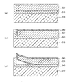
- the positive electrode lead foil 220 is corroded by the sulfuric acid contained in the electrolyte, and a coating 260 of corrosion products (lead oxide/lead sulfide) is formed on the surface of the positive electrode lead foil 220 . (see FIG. 7(b)). Then, there is a possibility that growth of the positive electrode lead foil 220 may occur due to the growth of the film 260 of the corrosion product.
- a reactive curing adhesive is used for the adhesive layer 240.
- the reaction-curable adhesive include a type of adhesive that is cured by mixing a main agent containing an epoxy resin and a curing agent containing an amine compound, and reacting the main agent and the curing agent.
- Such reaction-curing adhesives can be cured at room temperature, but have low resistance to sulfuric acid contained in the electrolyte.
- the reaction curing adhesive as described above is used as the adhesive layer 240, the positive electrode lead foil 220 and the adhesive layer 240 are peeled off due to this growth, and the interface between the positive electrode lead foil 220 and the adhesive layer 240 There was a possibility that the electrolytic solution would enter into the , and corrosion of the positive electrode lead foil 220 due to sulfuric acid would further progress (see (c) in FIG. 7). As a result, if the corrosion reaches the back surface of the positive electrode lead foil 220 (the surface facing the bipolar plate 210), for example, a short circuit may occur and the performance of the battery may deteriorate.
- the electrolytic solution will enter the communication hole, and the sulfuric acid will pass through the communication hole and cause the separation between the bipolar plate and the negative electrode lead foil. There is also a possibility that it will enter the space and cause leakage, causing a voltage drop and performance deterioration.
- reaction curing adhesive is used for the adhesive layer 240, instead of using an amine compound as a curing agent, a curing agent that is highly resistant to sulfuric acid, such as an acid anhydride or phenolic curing agent, is used. It is also conceivable to use agents.
- the temperature required for curing is high, for example, around 180°C. Therefore, if the bipolar plate is made of, for example, ABS resin, the heat applied when bonding the positive electrode lead foil or the negative electrode lead foil to the bipolar plate may affect the bipolar plate.
- An object of the present invention is to provide a bipolar storage battery and a method for manufacturing the bipolar storage battery.
- a bipolar storage battery is a bipolar storage battery including a bipolar electrode having a positive electrode, a negative electrode, and a bipolar plate having a positive electrode on one surface and a negative electrode on the other surface.
- At least the first surface of the positive electrode metal foil constituting the positive electrode and the negative electrode metal foil constituting the negative electrode is composed of a main agent containing an epoxy resin and an acid anhydride or a phenol.
- a reactive curing type first adhesive that is cured by reaction with a curing agent containing one is provided, and the first surface provided with the first adhesive is arranged so as to face the bipolar plate, The positive electrode metal foil is adhered to the bipolar plate.
- a main agent containing an epoxy resin and an acid anhydride or a phenol are added to a first surface of a positive electrode metal foil or a negative electrode metal foil.
- the positive electrode metal foil or the negative electrode metal foil so that the first surface of the negative electrode metal foil faces one surface or the other surface of the bipolar plate provided with the second adhesive, or a step of inverting the negative electrode metal foil and placing it on one side or the other side of the bipolar plate; heating the second adhesive to bond the positive electrode metal foil or the negative electrode metal foil and the bipolar plate; and a step of adhering the plate.
- a bipolar storage battery is a bipolar electrode having a positive electrode, a negative electrode, and a bipolar plate having a positive electrode on one surface and a negative electrode on the other surface.
- the electrolytic solution is less likely to penetrate into each part such as the interface between the positive electrode and the adhesive and the communication holes, and the battery performance is less likely to deteriorate.
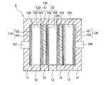
- FIG. 1 is a cross-sectional view showing the structure of a bipolar lead-acid battery according to an embodiment of the present invention
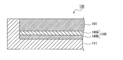
- FIG. 1 is an enlarged cross-sectional view of a bipolar electrode showing the structure of a main part of a bipolar lead-acid battery according to an embodiment of the invention
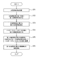
- FIG. 4 is a flow chart showing part of the flow of manufacturing a bipolar lead-acid battery according to an embodiment of the present invention.
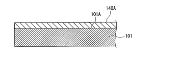
- FIG. 4 is an enlarged cross-sectional view of a bipolar electrode in part of the flow of manufacturing a bipolar lead-acid battery according to an embodiment of the present invention;
- FIG. 4 is an enlarged cross-sectional view of a bipolar electrode in part of the flow of manufacturing a bipolar lead-acid battery according to an embodiment of the present invention
- FIG. 4 is an enlarged cross-sectional view of a bipolar electrode in part of the flow of manufacturing a bipolar lead-acid battery according to an embodiment of the present invention
- Fig. 3 shows a conventional bipolar lead-acid battery in which the positive electrode lead foil grows due to corrosion caused by sulfuric acid contained in the electrolyte, resulting in the penetration of the electrolyte into the interface between the positive electrode lead foil and the adhesive layer. is.
- FIG. 1 is a cross-sectional view illustrating the structure of a bipolar lead-acid battery 1 according to an embodiment of the invention.
- the bipolar lead-acid battery 1 shown in FIG. A second plate unit fixed inside and a bipolar electrode 130 having a positive electrode 120 provided on one surface of a bipolar plate 111 and a negative electrode 110 provided on the other surface are attached to a frame plate-shaped third plate (rim) 13. It has a third plate unit fixed inside and a fourth plate unit in which the positive electrode 120 is fixed to a flat fourth plate (end plate) 14 .
- the bipolar lead-acid battery 1 having a substantially rectangular parallelepiped shape is configured.
- the numbers of the stacked second plate units and the number of the third plate units are set so that the storage capacity of the bipolar lead-acid battery 1 becomes a desired value.
- a negative electrode terminal 107 is fixed to the first plate 11, and the negative electrode 110 fixed to the first plate 11 and the negative electrode terminal 107 are electrically connected.
- a positive electrode terminal 108 is fixed to the fourth plate 14 , and a positive electrode 120 fixed to the fourth plate 14 and the positive electrode terminal 108 are electrically connected.
- the first plate 11 to fourth plate 14 are made of, for example, known molding resin. These first plate 11 to fourth plate 14 are fixed to each other by a suitable method so that the inside thereof is sealed so that the electrolytic solution does not flow out.
- the electrolytic layer 105 is composed of, for example, a glass fiber mat impregnated with an electrolytic solution containing sulfuric acid.
- the bipolar plate 111 is made of thermoplastic resin, for example.
- the thermoplastic resin forming the bipolar plate 111 include acrylonitrile-butadiene-styrene copolymer (ABS resin) and polypropylene. These thermoplastic resins have excellent moldability and excellent sulfuric acid resistance. Therefore, even if the electrolyte comes into contact with the bipolar plate 111, the bipolar plate 111 is unlikely to be decomposed, deteriorated, corroded, or the like.
- the positive electrode 120 is made of lead or a lead alloy and is arranged on one side of the bipolar plate 111.
- the positive electrode metal foil 101 (hereinafter referred to as "positive electrode and a positive electrode active material layer 103 disposed on the positive electrode lead foil 101 .
- the positive electrode lead foil 101 is adhered to one surface of the bipolar plate 111 by an adhesive 140 (not shown in FIG. 1) provided between one surface of the bipolar plate 111 and the positive electrode lead foil 101. there is Therefore, the adhesive 140, the positive electrode lead foil 101, and the positive electrode active material layer 103 are placed on one surface of the bipolar plate 111 (the surface facing upward in the drawings such as FIG. 2 to be described later). Laminated in order of description.
- the negative electrode 110 is made of lead or a lead alloy and is arranged on the other surface of the bipolar plate 111.
- the negative electrode metal foil 102 (hereinafter referred to as “negative electrode and a negative electrode active material layer 104 disposed on the negative electrode lead foil 102 .
- the negative electrode lead foil 102 is adhered to the other surface of the bipolar plate 111 with an adhesive 140 provided between the other surface of the bipolar plate 111 and the negative electrode lead foil 102 .
- the positive electrode 120 and the negative electrode 110 are electrically connected by an appropriate method such as via communication holes provided in the bipolar plate 111, for example.
- the bipolar plate 111, the positive electrode lead foil 101, the positive electrode active material layer 103, the negative electrode lead foil 102, and the A bipolar electrode 130 is configured by the negative electrode active material layer 104 .
- a bipolar electrode is a single electrode that functions as both a positive electrode and a negative electrode.
- a plurality of cell members each having an electrolytic layer 105 interposed between the positive electrode 120 and the negative electrode 110 are alternately laminated and assembled, thereby separating the cell members. It has a battery configuration connected in series.
- FIG. 2 is an enlarged cross-sectional view of bipolar electrode 130 showing the structure of the main part of bipolar lead-acid battery 1 according to the embodiment of the present invention.
- FIG. 2 is an enlarged cross-sectional view of bipolar electrode 130 showing the structure of the main part of bipolar lead-acid battery 1 according to the embodiment of the present invention.
- the cross-sectional views of the bipolar electrode 130 including FIG. The illustration of the structure of is omitted.
- the adhesive 140 is used for joining the positive electrode lead foil 101 and the bipolar plate 111 as described above. I know. That is, the first adhesive 140A provided on the positive electrode lead foil 101 and the second adhesive 140B provided on the bipolar plate 111 are provided.
- the adhesive used for the first adhesive 140A and the second adhesive 140B is a so-called reaction-curing adhesive, and the main agent contains an epoxy resin.
- the curing agents used for the first adhesive 140A and the second adhesive 140B are different.
- the positive electrode lead foil 101 is provided with the first adhesive 140A. As described above, one surface of the positive electrode lead foil 101 faces the bipolar plate 111 and is bonded to the bipolar plate 111 , and the other surface is in contact with the positive electrode active material layer 103 .
- One surface of the positive electrode lead foil 101 that faces the bipolar plate 111 and is joined to the bipolar plate 111 is hereinafter appropriately referred to as a "first surface”.
- the other surface in contact with the positive electrode active material layer 103 is the second surface.
- the first adhesive 140A is used to bond the positive electrode lead foil 101 to the bipolar plate 111, the first adhesive 140A is provided on the first surface 101A of the positive electrode lead foil 101.
- the first adhesive 140A provided on the positive electrode lead foil 101 is provided on the entire surface of the first surface 101A.
- the epoxy resin contained in the main agent includes, for example, at least one of bisphenol A type epoxy resin and bisphenol F type epoxy resin. Moreover, an epoxy resin may be used individually by 1 type, or may use 2 or more types together.
- examples of curing agents used in the first adhesive 140A include acid anhydrides and phenolic curing agents.
- the reason why these acid anhydrides and phenolic curing agents are used as curing agents is that they are highly resistant to sulfuric acid. That is, by providing such first adhesive 140A to the positive electrode lead foil 101, sulfuric acid may enter between the positive electrode lead foil 101 and the first adhesive 140A, causing the two to separate. can be avoided.
- acid anhydrides here include aromatic carboxylic acid anhydrides, aliphatic acid anhydrides, and alicyclic acid anhydrides.
- aromatic carboxylic anhydrides include phthalic anhydride, trimellitic anhydride, pyromellitic anhydride, benzophenonetetracarboxylic anhydride, and ethylene glycol trimellitic anhydride.
- aliphatic acid anhydrides include azelaic acid, sebacic acid, dodecanedioic acid, and the like.
- alicyclic acid anhydrides include, for example, tetrahydrophthalic anhydride (THPA), hexahydrophthalic anhydride (HHPA), methyltetrahydrophthalic anhydride (Me-THPA), methylhexahydrophthalic anhydride (Me- HHPA) nadic acid anhydride (NMA), hymic acid anhydride (MHAC) het acid anhydride, and the like.
- phenolic curing agents include, for example, bisphenol A, tetrabromobisphenol A, bisphenol F, bisphenol S, 4,4'-biphenylphenol, 2,2'-methylene-bis(4-methyl-6-tert-butylphenol).
- a curing accelerator can be used for the acid anhydride or phenolic curing agent described above.
- the reason why the curing accelerator is used is that by using the curing accelerator, the temperature required for curing the acid anhydride or phenolic curing agent can be lowered and the curing time can be shortened. be. If the curing time can be shortened, the tact time required for manufacturing the bipolar lead-acid battery itself can be shortened.
- Curing accelerators include triphenylphosphine (TPP), tertiary amine (DMP-30: 2,4,6-tris(dimethylaminomethyl)phenol) and amine-based (DBU: 1,8-diazabicyclo[5.4 .0]undec-7-ene), imidazole (2PZ-CN: 1-(2-cyanoethyl)-2-phenylimidazole), borate ester, Lewis acid, organometallic compound, organic acid metal salt, etc. can be
- curing accelerators may be used singly or in combination of two or more. Moreover, the addition of the curing accelerator is preferably, for example, about 0.1% to 2% with respect to the epoxy resin that is the main agent.
- the thickness is provided to be 50 ⁇ m or more and 150 ⁇ m or less. More preferably, the thickness of the first adhesive 140A is 50 ⁇ m or more and 100 ⁇ m or less.
- the term “50 ⁇ m or more” is used because if the thickness of the first adhesive 140A is less than 50 ⁇ m, the effect of suppressing the growth becomes small when the thickness of the positive electrode lead foil 101 increases, which is not preferable. It is from.
- “150 ⁇ m or less” is not preferable because if the thickness of the first adhesive 140A exceeds 150 ⁇ m, it takes a predetermined time to cure the epoxy resin, and sulfuric acid tends to enter the communication holes during curing. It is from.
- the positive electrode lead foil 101 is provided with the first adhesive 140A as described above. It is provided before bonding the lead foil 101 and the bipolar plate 111 together.
- the bipolar plate 111 is made of ABS resin, its melting point is low. Therefore, if a high temperature is applied when the positive electrode lead foil 101 is adhered, the bipolar plate 111 is distorted. , may be affected by heat.
- the positive electrode lead foil 101 is provided with the first adhesive 140A before the positive electrode lead foil 101 and the bipolar plate 111 are adhered. If the positive electrode lead foil 101 is provided with the first adhesive 140A in advance, there is no need to consider the influence on the bipolar plate 111. FIG.
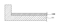
- the bipolar plate 111 is provided with a second adhesive 140B.
- the second adhesive 140B is used to bond the positive electrode lead foil 101 and the bipolar plate 111 together.
- the second adhesive 140B is provided on the bipolar plate 111 when the positive electrode lead foil 101 is adhered to the bipolar plate 111.
- the second adhesive 140B is provided on one surface of the bipolar plate 111 in a region where the positive electrode lead foil 101 is arranged.
- the positive electrode lead foil 101 and the bipolar plate 111 are bonded by the contact between the second adhesive 140B and the first adhesive 140A. Therefore, as the second adhesive 140B, any adhesive that can adhere to the first adhesive 140A is sufficient, but it is particularly preferable to use the second adhesive 140B described below.
- the epoxy resin contained in the main agent includes, for example, at least one of a bisphenol A type epoxy resin and a bisphenol F type epoxy resin, unlike the case of the first adhesive 140A. It is the same. Moreover, an epoxy resin may be used individually by 1 type, or may use 2 or more types together.
- a curing agent used for the second adhesive 140B for example, a curing agent containing a basic material can be used. Since such a curing agent can be adhered at, for example, room temperature, the bipolar plate 111 is less affected by heat during curing.
- the basic curing agent is, for example, an amine compound such as an aliphatic polyamine compound, an alicyclic polyamine compound, and an aromatic polyamine compound. These amine compounds may be used individually by 1 type, and may use 2 or more types together.
- aliphatic polyamine compound examples include aliphatic primary amines such as triethylenetetramine ( C6H18N4 ) and aliphatic secondary amines such as triethylenetetramine.
- aliphatic primary amines such as triethylenetetramine ( C6H18N4 )
- aliphatic secondary amines such as triethylenetetramine.
- alicyclic polyamine compounds include alicyclic primary amines such as isophoronediamine ( C10H22N2 ).
- aromatic polyamine compounds include aromatic primary amines such as diaminodiphenylmethane ( C13H14N2 ).
- the first adhesive 140A and the second adhesive 140B are arranged so that they face each other. Then, the positive electrode lead foil 101 and the bipolar plate 111 are adhered and cured by heating and melting the second adhesive 140B provided on the bipolar plate 111 .
- the positive electrode lead foil 101 is provided with the first adhesive 140A before bonding to the bipolar plate 111 .
- the positive electrode lead foil 101 and the first adhesive 140A are firmly adhered to each other.
- the first adhesive 140A and the second adhesive 140B are each formed with the composition described above, the bonding between the two is very strong. Therefore, the positive electrode lead foil 101 is firmly adhered to the bipolar plate 111 .
- the bipolar lead-acid battery 1 By adhering the positive electrode lead foil 101 to the bipolar plate 111 in this manner, the bipolar lead-acid battery 1 according to the embodiment of the present invention consists of the bipolar plate 111, the second adhesive 140B, and the first adhesive 140A. , and the positive electrode lead foil 101 .
- the positive electrode lead foil 101 and the bipolar plate 111 are firmly adhered to each other via the two-layered adhesive 140 as described above. Therefore, the bipolar plate 111, the second adhesive 140B, the first adhesive 140A, and the positive electrode lead foil 101 are less likely to separate from each other, and growth is less likely to occur. Even if growth occurs in the positive electrode due to corrosion due to sulfuric acid contained in the electrolytic solution, the electrolytic solution is less likely to penetrate into each part such as the interface between the positive electrode and the adhesive and the communication holes, and the battery performance is less likely to deteriorate.
- FIG. 3 is a flow chart showing part of the flow of manufacturing the bipolar lead-acid battery 1 according to the embodiment of the present invention.
- the positive electrode lead foil 101 is provided with the first adhesive 140A. That is, as shown in the flowchart of FIG. 3, the positive electrode lead foil 101 is prepared (ST1). Then, the first adhesive 140A having the composition as described above is provided on the entire first surface 101A of the positive electrode lead foil 101 (ST2).
- the positive electrode lead foil 101 and the first adhesive 140A are prepared, and the first adhesive 140A is filled in the screen provided with the adhesive pattern using, for example, a scraper of a high-precision screen printer. Then, the first adhesive 140A is transferred from the screen to the first surface 101A of the positive electrode lead foil 101 using a squeegee.
- FIG. 4 shows the positive electrode lead foil 101 in this state.
- a first adhesive 140A is provided on the first surface 101A of the positive electrode lead foil 101 . That is, the positive electrode lead foil 101 provided with the first adhesive 140A is completed.
- a second adhesive 140B is provided on one surface of the bipolar plate 111 on which the positive electrode lead foil 101 is provided (ST4).
- the composition of the second adhesive 140B is as described above. However, since the positive electrode lead foil 101 is not yet adhered at this point, the second adhesive 140B is not heated and cured. Therefore, the bipolar plate 111 shown in FIG. 5 shows a state where only the second adhesive 140B is piled up on one surface thereof.
- the positive electrode lead foil 101 is reversed so that the first adhesive 140A faces the second adhesive 140B, and one side of the bipolar plate 111 is attached. (ST5).
- two arrows indicate that the positive electrode lead foil 101 is inverted and placed on one surface of the bipolar plate 111 .
- the positive electrode lead foil 101 is placed on one side of the bipolar plate 111 in this way, they are heated and cured, thereby melting the second adhesive 140B and bonding the positive electrode lead foil 101 and the bipolar plate 111 together. are joined (ST6).
- the state in which the positive lead foil 101 is adhered to the bipolar plate 111 is the bipolar electrode 130 shown in FIG. 2 used in the above description.
- a positive electrode lead foil having the following configuration was prepared. That is, for the first adhesive provided on the positive electrode lead foil, the main agent is bisphenol A type liquid resin (manufactured by Nagase ChemteX Co., Ltd.: Araldite CY225), and the acidic curing agent is modified alicyclic acid anhydride (Nagasechem Hardener HY925)) manufactured by Tex Co., Ltd. was blended at a ratio of 100:80 and cured.
- the main agent is bisphenol A type liquid resin (manufactured by Nagase ChemteX Co., Ltd.: Araldite CY225)
- the acidic curing agent is modified alicyclic acid anhydride (Nagasechem Hardener HY925)) manufactured by Tex Co., Ltd. was blended at a ratio of 100:80 and cured.
- a bisphenol A liquid resin (manufactured by Nagase ChemteX Corporation: XNR3114) is used as the main agent, and an aliphatic polyamine compound is used as the base curing agent.
- An alicyclic primary amine such as isophoronediamine (C10H22N2), and XNH3114 manufactured by Nagase ChemteX Co., Ltd. was used. Then, the curing agent was mixed with the main agent at a ratio of 100:25 parts by weight and cured.
- the adhesive when bonding the positive electrode lead foil and the bipolar plate, the adhesive is provided so as to form two layers between the positive electrode lead foil and the bipolar plate. That is, the adhesive provided on the positive electrode lead foil is an adhesive that is highly resistant to sulfuric acid contained in the electrolyte.
- the positive electrode lead foil is provided with an adhesive in advance.
- the composition of the adhesive used for bonding the positive electrode lead foil and the bipolar plate is different from the composition of the adhesive provided on the positive electrode lead foil, and the composition is the same as before, for example, a composition that can be cured even at room temperature. agent is used. Therefore, the influence of heat on the bipolar plate during curing can be minimized. As a result, it is possible to ensure the adhesiveness when the positive electrode lead foil and the bipolar plate are adhered together, and also to have a high resistance to sulfuric acid.
- the electrolytic solution is less likely to penetrate into each part such as the interface between the positive electrode and the adhesive and the communication hole, and the battery performance is improved. It is possible to provide a bipolar storage battery in which deterioration is unlikely to occur and a method for manufacturing the bipolar storage battery.
- the first adhesive on the positive electrode lead foil as described above, even if cracks occur due to corrosion, the first adhesive does not easily spread. Furthermore, since the first adhesive is cured on the positive electrode lead foil at a high temperature, it is possible to expect effects such that the path of corrosion is less likely to spread and growth is less likely to occur.
Landscapes
- Chemical & Material Sciences (AREA)
- Chemical Kinetics & Catalysis (AREA)
- Electrochemistry (AREA)
- General Chemical & Material Sciences (AREA)
- Engineering & Computer Science (AREA)
- Materials Engineering (AREA)
- Manufacturing & Machinery (AREA)
- Organic Chemistry (AREA)
- Cell Electrode Carriers And Collectors (AREA)
Abstract
電解液に含有される硫酸による腐食によって正極にグロースが生じても、正極と接着剤との界面や連通孔といった各部に電解液が浸入しにくくなり、電池性能の低下が起こりにくくする。一方の面に正極(120)が設けられて他方の面に負極(110)が設けられたバイポーラプレート(111)を有するバイポーラ電極(130)を備えるバイポーラ型鉛蓄電池(1)であって、正極(120)を構成する正極用金属箔(101)の第1の面は、エポキシ樹脂を含有する主剤と酸無水物、或いは、フェノール類のいずれか一方を含有する硬化剤とが反応して硬化する反応硬化型の第1の接着剤(140A)を備え、第1の接着剤(140A)が設けられた第1の面がバイポーラプレート(111)の一方の面又は他方の面に設けられる第2の接着剤(140B)に対向するように配置され、正極用金属箔(101)がバイポーラプレート(111)に接着される。
Description
本発明の実施の形態は、バイポーラ型蓄電池及びバイポーラ型蓄電池の製造方法に関する。
従来の鉛蓄電池では、例えば、額縁形をなす樹脂からなるフレーム(リム)の内側に、樹脂からなる基板(以下、この基板のことを、適宜「バイポーラプレート」と表わす。)が取り付けられている。バイポーラプレートの一方面及び他方面には、正極用鉛箔及び負極用鉛箔が配設されている。正極用鉛箔には、正極用活物質層が隣接している。負極用鉛箔には、負極用活物質層が隣接している。
すなわち、例えば従来のバイポーラ電極の正極は、図7の(a)に示すように、樹脂製のバイポーラプレート210の一方の面の上に接着剤層240を介して正極用鉛箔220が配置され、さらに当該正極用鉛箔220の上に正極用活物質層(図示せず)が配置されることによって構成されている。また、額縁形をなす樹脂からなるスペーサの内側には、電解液を含有するガラスマット(電解層)が配設されている。そして、フレームとスペーサとが交互に複数積層されて組み付けられている。
さらに正極用鉛箔と負極用鉛箔とが、バイポーラプレートに複数形成された穿孔の内部で接合される場合もある。このような鉛蓄電池は、一方面側と他方面側とを連通させる穿孔(連通孔)を有するバイポーラプレートとセル部材とが交互に複数積層された双極(バイポーラ)型鉛蓄電池である。セル部材は、正極用鉛箔に正極用活物質層を設けた正極と、負極用鉛箔に負極用活物質層を設けた負極と、正極と負極との間に介在する電解層と、を有し、一方のセル部材の正極用鉛箔と他方のセル部材の負極用鉛箔とがバイポーラプレートの連通孔を介して接合されることにより、セル部材同士が直列に接続される。
上記のようなバイポーラ型鉛蓄電池においては、電解液に含有される硫酸によって正極用鉛箔220が腐食して正極用鉛箔220の表面に腐食生成物(酸化鉛・硫化鉛)の被膜260が生成されることがある(図7の(b)を参照)。そして、この腐食生成物の被膜260の成長によって正極用鉛箔220に伸び(グロース)が生じるおそれがあった。
ここで接着剤層240としては、例えば、反応硬化型接着剤が用いられる。この反応硬化型接着剤としては、例えばエポキシ樹脂を含有する主剤とアミン化合物を含有する硬化剤とを混合し、主剤と硬化剤とを反応させて硬化させるタイプの接着剤を挙げることができる。このような反応硬化型接着剤は、常温で硬化させることが可能である一方、電解液に含有される硫酸には耐性が低い面もある。
そのため、接着剤層240として上述したような反応硬化型接着剤を用いると、このグロースによって正極用鉛箔220と接着剤層240が剥離し、正極用鉛箔220と接着剤層240との界面に電解液が浸入して、硫酸による正極用鉛箔220の腐食がさらに進行するおそれがあった(図7の(c)を参照)。その結果、腐食が例えば正極用鉛箔220の裏面(バイポーラプレート210に対向する面)にまで達すると、短絡が生じるなどして電池の性能が低下する場合があった。
また、バイポーラプレートの連通孔付近において正極用鉛箔と接着剤層が剥離してしまうと、連通孔に電解液が浸入して、硫酸が連通孔を介してバイポーラプレートと負極用鉛箔との間に浸入して液洛を生じてしまい、電圧低下を引き起こして性能低下を生じてしまうおそれもある。
そこで接着剤層240に上述した反応硬化型接着剤を用いるとしても、硬化剤としてアミン化合物を使用するのではなく、硫酸への耐性が高い硬化剤である、例えば、酸無水物やフェノール類硬化剤を使用することも考えられる。
これら酸無水物やフェノール類硬化剤は硫酸への耐性は高いものの、例えば、180℃前後といった、硬化に必要な温度が高い。そのためバイポーラプレートが、例えばABS樹脂で形成されている場合には、正極用鉛箔、或いは、負極用鉛箔をバイポーラプレートに接着する際に加えられる熱がバイポーラプレートに影響を与えてしまう可能性がある。
本発明は、電解液に含有される硫酸による腐食によって正極にグロースが生じても、正極と接着剤との界面や連通孔といった各部に電解液が浸入しにくくなり、電池性能の低下が起こりにくいバイポーラ型蓄電池及びバイポーラ型蓄電池の製造方法を提供することを目的とする。
本発明の一態様に係るバイポーラ型蓄電池は、正極及び負極と、一方の面に正極が設けられて他方の面に負極が設けられたバイポーラプレートと、を有するバイポーラ電極を備えるバイポーラ型蓄電池であって、正極を構成する正極用金属箔及び負極を構成する負極用金属箔の少なくとも正極用金属箔の第1の面は、エポキシ樹脂を含有する主剤と酸無水物、或いは、フェノール類のいずれか一方を含有する硬化剤とが反応して硬化する反応硬化型の第1の接着剤を備え、第1の接着剤が設けられた第1の面がバイポーラプレートに対向するように配置されて、正極用金属箔がバイポーラプレートに接着されていることを特徴とする。
本発明の一態様に係るバイポーラ型蓄電池の製造方法は、正極用金属箔、または、負極用金属箔の第1の面にエポキシ樹脂を含有する主剤と酸無水物、或いは、フェノール類のいずれか一方を含有する硬化剤とが反応して硬化する反応硬化型の第1の接着剤を設ける工程と、第1の接着剤を加熱して硬化させる工程と、バイポーラプレートの一方の面、または、他方の面にエポキシ樹脂を含有する主剤と塩基性素材を含有する硬化剤とが反応して硬化する反応硬化型の第2の接着剤を設ける工程と、第1の接着剤が設けられた正極用金属箔、または、負極用金属箔の第1の面が、第2の接着剤が設けられたバイポーラプレートの一方の面、または、他方の面に対向するように正極用金属箔、または、負極用金属箔を反転させてバイポーラプレートの一方の面、または、他方の面に載置する工程と、第2の接着剤を加熱して正極用金属箔、または、負極用金属箔と前記バイポーラプレートとを接着する工程と、を備えていることを特徴とする。
このように、本発明の一態様に係るバイポーラ型蓄電池は、正極及び負極と、一方の面に正極が設けられて他方の面に負極が設けられたバイポーラプレートと、を有するバイポーラ電極を備えるバイポーラ型蓄電池であって、正極を構成する正極用金属箔及び負極を構成する負極用金属箔の少なくとも正極用金属箔の第1の面は、エポキシ樹脂を含有する主剤と酸無水物、或いは、フェノール類のいずれか一方を含有する硬化剤とが反応して硬化する反応硬化型の第1の接着剤を備え、第1の接着剤が設けられた第1の面がバイポーラプレートに対向するように配置されて、正極用金属箔がバイポーラプレートに接着されている。そのため、電解液に含有される硫酸による腐食によって正極にグロースが生じても、正極と接着剤との界面や連通孔といった各部に電解液が浸入しにくくなり、電池性能の低下が起こりにくい。
以下、本発明の実施の形態について図面を参照して詳細に説明する。なお、以下に説明する実施の形態は、本発明の一例を示したものである。また、本実施の形態には種々の変更又は改良を加えることが可能であり、その様な変更又は改良を加えた形態も本発明に含まれ得る。この実施形態やその変形は、発明の範囲や要旨に含まれると共に、特許請求の範囲に記載された発明とその均等の範囲に含まれる。なお、以下においては、様々な蓄電池の中から鉛蓄電池を例に挙げて説明する。
本発明の実施の形態に係るバイポーラ型鉛蓄電池1の構造を、図1を参照しながら説明する。図1は、本発明の実施の形態に係るバイポーラ型鉛蓄電池1の構造を説明する断面図である。
図1に示すバイポーラ型鉛蓄電池1は、負極110を平板形状の第1プレート(エンドプレート)11に固定した第1プレートユニットと、電解層105を枠板形状の第2プレート(スペーサ)12の内側に固定した第2プレートユニットと、バイポーラプレート111の一方の面に正極120が設けられて他方の面に負極110が設けられたバイポーラ電極130を枠板形状の第3プレート(リム)13の内側に固定した第3プレートユニットと、正極120を平板形状の第4プレート(エンドプレート)14に固定した第4プレートユニットと、を有する。
そして、第2プレートユニット及び第3プレートユニットが第1プレートユニットと第4プレートユニットの間で交互に積層されることによって、例えば、略直方体形状をなすバイポーラ型鉛蓄電池1が構成される。積層される第2プレートユニットと第3プレートユニットのそれぞれの個数は、バイポーラ型鉛蓄電池1の蓄電容量が所望の数値になるように設定される。
第1プレート11には負極端子107が固定されており、当該第1プレート11に固定された負極110と負極端子107とが電気的に接続されている。第4プレート14には正極端子108が固定されており、当該第4プレート14に固定された正極120と正極端子108とが電気的に接続されている。
第1プレート11ないし第4プレート14は、例えば周知の成形樹脂によって形成されている。そして、これら第1プレート11ないし第4プレート14は、電解液の流出が無いように、適宜の方法で内部が密閉状態となるよう互いに固定されている。
電解層105は、例えば、硫酸を含有する電解液が含浸されたガラス繊維マットによって構成されている。
バイポーラプレート111は、例えば、熱可塑性樹脂で形成されている。バイポーラプレート111を形成する熱可塑性樹脂としては、例えば、アクリロニトリル-ブタジエン-スチレン共重合体(ABS樹脂)、ポリプロピレンが挙げられる。これらの熱可塑性樹脂は、成形性が優れているとともに耐硫酸性も優れている。よって、バイポーラプレート111に電解液が接触したとしても、バイポーラプレート111に分解、劣化、腐食等が生じにくい。
正極120は、鉛又は鉛合金からなり且つバイポーラプレート111の一方の面の上に配置される正極用金属箔101(以下においては、当該金属箔が鉛又は鉛合金からなることを前提に「正極用鉛箔101」と表す)と、正極用鉛箔101の上に配置される正極用活物質層103と、を備えている。この正極用鉛箔101は、バイポーラプレート111の一方の面と正極用鉛箔101の間に設けられる、図1においては図示されていない接着剤140によってバイポーラプレート111の一方の面に接着されている。従って、バイポーラプレート111の一方の面(後述する図2等の図面においては、紙面における上方を向く面)の上に、接着剤140、正極用鉛箔101、正極用活物質層103が、この記載順に積層されている。
負極110は、鉛又は鉛合金からなり且つバイポーラプレート111の他方の面の上に配置される負極用金属箔102(以下においては、当該金属箔が鉛又は鉛合金からなることを前提に「負極用鉛箔102」と表す)と、負極用鉛箔102の上に配置される負極用活物質層104と、を備えている。この負極用鉛箔102は、バイポーラプレート111の他方の面と負極用鉛箔102の間に設けられる接着剤140によってバイポーラプレート111の他方の面に接着されている。そしてこれら正極120と負極110は、例えば、バイポーラプレート111に設けられる連通孔を介する等の適宜の方法で電気的に接続されている。
このような構成を有する第1の実施の形態のバイポーラ型鉛蓄電池1においては、上述したように、バイポーラプレート111、正極用鉛箔101、正極用活物質層103、負極用鉛箔102、及び負極用活物質層104によって、バイポーラ電極130が構成されている。バイポーラ電極とは、1枚の電極で正極、負極両方の機能を有する電極である。そして、本発明の実施の形態のバイポーラ型鉛蓄電池1は、正極120と負極110との間に電解層105を介在させてなるセル部材を交互に複数積層して組み付けることにより、セル部材同士を直列に接続した電池構成を有している。
図2は、本発明の実施の形態に係るバイポーラ型鉛蓄電池1の要部の構造を示すバイポーラ電極130の拡大断面図である。なお、以下に示す図2をはじめとするバイポーラ電極130の断面図においては、例えば、バイポーラプレート111の他方の面に設けられる負極110等、バイポーラプレート111、接着剤140及び正極用鉛箔101以外の構造については、その図示を省略している。
本発明の実施の形態におけるバイポーラ型鉛蓄電池1では、正極用鉛箔101とバイポーラプレート111との接合に当たっては、上述したように接着剤140が使用されるが、当該接着剤140は2層に分かれている。すなわち、正極用鉛箔101に設けられる第1の接着剤140Aとバイポーラプレート111に設けられる第2の接着剤140Bである。
第1の接着剤140A及び第2の接着剤140Bに使用される接着剤は、いわゆる反応硬化型接着剤であり、主剤にはエポキシ樹脂が含有される。但し、第1の接着剤140A及び第2の接着剤140Bに使用される硬化剤は各々異なるものである。
まず、正極用鉛箔101には、第1の接着剤140Aが設けられている。上述したように正極用鉛箔101は、その一方の面がバイポーラプレート111に対向して接合され、他方の面は正極用活物質層103と接している。なお、正極用鉛箔101のうちバイポーラプレート111に対向して接合される一方の面を、以下、適宜「第1の面」と表す。一方、正極用活物質層103と接する他方の面は、第2の面である。
第1の接着剤140Aは正極用鉛箔101をバイポーラプレート111と接着させるために用いられるため、この第1の接着剤140Aは、正極用鉛箔101の第1の面101Aに設けられる。そして、正極用鉛箔101に設けられる第1の接着剤140Aは、第1の面101Aの全面に設けられる。
第1の接着剤140Aにおいて、主剤に含有されるエポキシ樹脂としては、例えば、ビスフェノールA型エポキシ樹脂及びビスフェノールF型エポキシ樹脂の少なくとも一方が挙げられる。また、エポキシ樹脂は、1種を単独で使用しても良く、或いは、2種以上を併用しても良い。
一方、第1の接着剤140Aで用いられる硬化剤としては、例えば、酸無水物やフェノール類硬化剤が挙げられる。これら酸無水物やフェノール類硬化剤を硬化剤として使用するのは、硫酸への耐性が強いからである。すなわち、このような第1の接着剤140Aを正極用鉛箔101に設けることによって、硫酸が正極用鉛箔101と第1の接着剤140Aとの間に浸入して両者が剥離してしまうことを回避することができる。
ここで酸無水物としては、例えば、芳香族カルボン酸無水物、脂肪族酸無水物、或いは、脂環式酸無水物を挙げることができる。このうち芳香族カルボン酸無水物は、例えば、フタル酸無水物、トリメリット酸無水物、ピロメリット酸無水物、ベンゾフェノンテトラカルボン酸無水物、エチレングリコール無水トリメリット酸などである。
また、脂肪族酸無水物としては、例えば、アゼライン酸、セバシン酸、ドデカン二酸等などが挙げられる。さらに脂環式酸無水物としては、例えば、テトラヒドロフタル酸無水物(THPA)、ヘキサヒドロフタル酸無水物(HHPA)、メチルテトラヒドロ無水フタル酸(Me-THPA)メチルヘキサヒドロ無水フタル酸(Me-HHPA)ナジック酸無水物(NMA)、ハイミック酸無水物(MHAC)ヘット酸無水物、等を挙げることができる。
一方フェノール類硬化剤としては、例えばビスフェノールA、テトラブロムビスフェノールA、ビスフェノールF、ビスフェノールS、4,4’-ビフェニルフェノール、2,2’-メチレン-ビス(4-メチル-6-tert-ブチルフェノール)、2,2’-メチレン-ビス(4-エチル-6-tert-ブチルフェノール)、4,4’-ブチリレン-ビス(3-メチル-6-tert-ブチルフェノール)、1,1,3-トリス(2-メチル-4-ヒドロキシ-5-tert-ブチルフェノール),トリスヒドロキシフェニルメタン、ピロガロール、ジイソプロピリデン骨格を有するフェノール類、1,1-ジ-4-ヒドロキシフェニルフルオレン等のフルオレン骨格を有するフェノール類、フェノール化ポリブタジエン等のポリフェノール化合物、フェノール、クレゾール類、エチルフェノール類、ブチルフェノール類、オクチルフェノール類、ビスフェノールA、ブロム化ビスフェノールA、ビスフェノールF、ビスフェノールS、ナフトール類等の各種フェノールを原料とするノボラック樹脂、キシリレン骨格含有フェノールノボラック樹脂、ジシクロペンタジエン骨格含有フェノールノボラック樹脂、フルオレン骨格含有フェノールノボラック樹脂等の各種ノボラック樹脂等を挙げることができる。
また、上述した酸無水物、或いは、フェノール類硬化剤に対しては、さらに硬化促進剤を使用することができる。硬化促進剤を使用するのは、硬化促進剤を使用することで元々酸無水物、或いは、フェノール類硬化剤の硬化に必要な温度を下げることができ、硬化時間を短縮することができるからである。硬化時間を短縮することができると、バイポーラ型鉛蓄電池の製造自体に掛かるタクトタイムの短縮につながる。
硬化促進剤としては、トリフェニルホスフィン(TPP)、三級アミン(DMP-30:2,4,6-トリス(ジメチルアミノメチル)フェノール)やアミン系(DBU:1,8-ジアザビシクロ[5.4.0]ウンデカ-7-エン)、イミダゾール(2PZ-CN:1-(2-シアノエチル)-2-フェニルイミダゾール)、ホウ酸エステル、ルイス酸、有機金属化合物、有機酸金属塩、などを使用しても良い。
なおこれらの硬化促進剤については、1種を単独で使用しても良く、或いは、2種以上を併用することとしても良い。また、硬化促進剤の添加は、主剤であるエポキシ樹脂に対して、例えば、0.1%ないし2%程度が良い。
上述したような第1の接着剤140Aを正極用鉛箔101に対して設ける場合、その厚みは、50μm以上150μm以下の厚みとなるように設けられる。なお、より好ましくは、第1の接着剤140Aの厚みは50μm以上100μm以下の厚みであると良い。
ここで「50μm以上」とするのは、第1の接着剤140Aの厚みが50μm未満の厚みであると、正極用鉛箔101の厚みが増した場合にグロースを押さえる効果が小さくなり、好ましくないからである。一方、「150μm以下」とするのは、第1の接着剤140Aの厚みが150μmを超えると、エポキシ樹脂の硬化に所定の時間が掛かり、硬化時に硫酸が連通孔に浸入しやすくなるため好ましくないからである。
正極用鉛箔101に対しては、上述したような第1の接着剤140Aが設けられるが、これは、正極用鉛箔101とバイポーラプレート111とを接着させる際に設けるのではなく、正極用鉛箔101とバイポーラプレート111とを接着させる前に設けられるものである。
すなわち、上述したように、バイポーラプレート111が、特にABS樹脂で形成されている場合には、その融点が低いため、正極用鉛箔101を接着するに当たって高い温度を掛けるとバイポーラプレート111がゆがむ等、熱による影響が考えられる。
そこで、本発明の実施の形態におけるバイポーラ型鉛蓄電池1を製造するに当たっては、正極用鉛箔101とバイポーラプレート111とを接着させる前に正極用鉛箔101に第1の接着剤140Aを設ける。このように事前に正極用鉛箔101に第1の接着剤140Aを設けるのであれば、バイポーラプレート111への影響を考慮する必要がない。
そのため、これまでバイポーラプレート111への影響から使用することができなかった、接着に当たって高い温度を必要する接着剤を使用することができる。そして上述したようなエポキシ樹脂及び硬化剤、硬化促進剤を使用することによって、電解液に含有される硫酸への耐性を高めることができる。
次に、図2に示すように、バイポーラプレート111には第2の接着剤140Bが設けられている。この第2の接着剤140Bは、正極用鉛箔101とバイポーラプレート111とを接着させる際に使用されるものである。
そのため、第2の接着剤140Bは、正極用鉛箔101をバイポーラプレート111に接着させる際にバイポーラプレート111に設けられるものである。そして、第2の接着剤140Bは、バイポーラプレート111の一方の面上であって、正極用鉛箔101が配置される領域に設けられる。
従って、当該第2の接着剤140Bと第1の接着剤140Aとが接触することによって正極用鉛箔101とバイポーラプレート111とが接着される。そのため、第2の接着剤140Bについては、第1の接着剤140Aと接着することができる接着剤であれば足りるが、以下に説明する第2の接着剤140Bが用いられると特に好ましい。
すなわち第2の接着剤140Bにおいて、主剤に含有されるエポキシ樹脂としては、例えば、ビスフェノールA型エポキシ樹脂及びビスフェノールF型エポキシ樹脂の少なくとも一方が挙げられることは、第1の接着剤140Aの場合と同様である。また、エポキシ樹脂は、1種を単独で使用しても良く、或いは、2種以上を併用しても良い。
第2の接着剤140Bに用いられる硬化剤としては、例えば、塩基性素材を含有する硬化剤を挙げることができる。このような硬化剤は、接着の際の温度が、例えば、常温で足りるので、硬化に当たってバイポーラプレート111に熱の影響を与えることが少ない。
塩基性硬化剤は、例えば、アミン化合物であり、例えば、脂肪族ポリアミン化合物、脂環族ポリアミン化合物、芳香族ポリアミン化合物を挙げることができる。これらのアミン化合物は、1種を単独で使用してもよいし、2種以上を併用してもよい。
脂肪族ポリアミン化合物の具体例としては、トリエチレンテトラミン(C6H18N4)等の脂肪族第一級アミン、トリエチレンテトラミン等の脂肪族第二級アミンが挙げられる。脂環族ポリアミン化合物の具体例としては、イソホロンジアミン(C10H22N2)等の脂環族第一級アミンが挙げられる。芳香族ポリアミン化合物の具体例としては、ジアミノジフェニルメタン(C13H14N2)等の芳香族第一級アミンが挙げられる。
このような第2の接着剤140Bを備えるバイポーラプレート111と上述した第1の接着剤140Aを備える正極用鉛箔101とを接着させる場合、第1の接着剤140Aと第2の接着剤140Bとが互いに対向するように正極用鉛箔101及びバイポーラプレート111を配置する。そしてバイポーラプレート111に設けられた第2の接着剤140Bを加熱溶融することで正極用鉛箔101とバイポーラプレート111とを接着し、硬化させる。
上述したように、バイポーラプレート111との接着の前に、正極用鉛箔101には第1の接着剤140Aが設けられている。そして、正極用鉛箔101と第1の接着剤140Aとは互いに強固に接着している。また、第1の接着剤140A及び第2の接着剤140Bとは、それぞれ上述したような組成で形成されていることから、両者の接合は非常に強固である。従って、正極用鉛箔101はバイポーラプレート111に強固に接着される。
このように正極用鉛箔101がバイポーラプレート111に接着されることによって、本発明の実施の形態におけるバイポーラ型鉛蓄電池1は、バイポーラプレート111、第2の接着剤140B、第1の接着剤140A、正極用鉛箔101の順に積層される。
本発明の実施の形態におけるバイポーラ型鉛蓄電池1は、このように2層となる接着剤140を介して正極用鉛箔101とバイポーラプレート111とが強固に接着されている。そのため、バイポーラプレート111、第2の接着剤140B、第1の接着剤140A、正極用鉛箔101のそれぞれが互いに剥離しにくく、そもそもグロースが生じにくい。そして、たとえ電解液に含有される硫酸による腐食によって正極にグロースが生じても、正極と接着剤との界面や連通孔といった各部に電解液が浸入しにくくなり、電池性能の低下が起こりにくい。
次に、図3ないし図6を用いて、本発明の実施の形態におけるバイポーラ型鉛蓄電池の製造方法について説明する。図3は、本発明の実施の形態に係るバイポーラ型鉛蓄電池1の製造の一部の流れを示すフローチャートである。
すなわち、バイポーラ型鉛蓄電池を製造する流れのうち、バイポーラプレート111の一方の面に正極用鉛箔101を設ける工程を抜き出して示したものである。また、図4ないし図6は、本発明の実施の形態に係るバイポーラ型鉛蓄電池1の製造の一部の流れにおけるバイポーラ電極の拡大断面図である。
まずここでは、正極用鉛箔101に第1の接着剤140Aを設ける。すなわち、図3のフローチャートに示すように、正極用鉛箔101を用意する(ST1)。その上で、正極用鉛箔101の第1の面101Aの全面に上述したような組成を有する第1の接着剤140Aを設ける(ST2)。
具体的には、以下のような流れを経る。すなわち、正極用鉛箔101と第1の接着剤140Aとを用意し、例えば、高精密スクリーン印刷機のスクレーパーを用いて接着パターンが設けられたスクリーンに第1の接着剤140Aを充填する。そして、スキージを用いてスクリーンから第1の接着剤140Aを正極用鉛箔101の第1の面101Aに転写する。
そして、例えば150℃の環境下において4時間以上掛けて第1の接着剤140Aを硬化させる(ST3)。図4は、この状態の正極用鉛箔101を示している。正極用鉛箔101の第1の面101Aには、第1の接着剤140Aが設けられている。すなわち、第1の接着剤140Aを備える正極用鉛箔101が出来上がる。
次に、正極用鉛箔101が設けられるバイポーラプレート111の一方の面に、第2の接着剤140Bを設ける(ST4)。第2の接着剤140Bの組成については上述した通りである。但し、この時点では未だ正極用鉛箔101を接着しないので、第2の接着剤140Bに対して加熱、硬化処理を行わない。そのため、図5に示されているバイポーラプレート111は、その一方の面に第2の接着剤140Bが盛られただけの状態を示している。
そしてこのような状態のバイポーラプレート111の一方の面に対して、第2の接着剤140Bに第1の接着剤140Aが対向するように、正極用鉛箔101を反転させてバイポーラプレート111の一方の面に載置する(ST5)。図6では、正極用鉛箔101を反転させてバイポーラプレート111の一方の面に載置することを2つの矢印で示している。
このように正極用鉛箔101をバイポーラプレート111の一方の面に載置した後、これらを加熱、硬化させることで、第2の接着剤140Bが溶融し、正極用鉛箔101とバイポーラプレート111とが接合される(ST6)。この正極用鉛箔101がバイポーラプレート111に接着された状態を示すのが、上述の説明で用いた図2に示すバイポーラ電極130である。
ここで、実施例として、以下の構成を備える正極用鉛箔を用意した。すなわち、正極用鉛箔に設ける第1の接着剤について、その主剤としてビスフェノールA型液状樹脂(ナガセケムテックス(株)製:アラルダイトCY225)、酸性硬化剤として変性脂環式酸無水物(ナガセケムテックス(株)製:ハードナーHY925))を100:80の割合で配合して用い、硬化させた。
また、バイポーラプレートに設ける第2の接着剤については、その主剤としてビスフェノールA型液状樹脂(ナガセケムテックス(株)製:XNR3114)を用い、塩基硬化剤として脂肪族ポリアミン化合物、具体的には、イソホロンジアミン(C10H22N2)といった脂環族第一級アミンであり、ナガセケムテックス(株)製:XNH3114を使用した。そして、当該硬化剤を主剤と100:25重量部の割合で混合し硬化させた。
その結果、温度60℃の硫酸に4週間浸漬した場合でも、正極用鉛層と接着剤との界面に硫酸が侵入しなかった。
以上説明したバイポーラ型鉛蓄電池では、正極用鉛箔とバイポーラプレートとを接着する際に、正極用鉛箔とバイポーラプレートとの間で2層となるように接着剤を設ける。すなわち、正極用鉛箔に設けられる接着剤は、電解液に含有される硫酸への耐性が強い接着剤である。
但し、この硫酸への耐性が強い接着剤を硬化させるためには、高温での硬化を必要とする。そこで、正極用鉛箔をバイポーラプレートに接着させる前に、予め正極用鉛箔に接着剤を設けることとした。このように事前に正極用鉛箔に接着剤を設けることによって、高温での硬化が必要であっても硫酸への耐性を確保しつつ、バイプレートに硬化における熱の影響を与えることを避けることができる。
一方、正極用鉛箔とバイポーラプレートとを接着する際に使用する接着剤の組成は、正極用鉛箔に設けられる接着剤の組成とは異なり、これまで通り、例えば常温でも硬化できる組成の接着剤が使用される。そのため、硬化の際にバイポーラプレートに対して与える熱の影響を最小限に抑えることができる。これによって、正極用鉛箔とバイポーラプレートとを接着させた際の接着性を確保することができるとともに、硫酸に対しても高い耐性を有することになる。
従って、本発明によれば、電解液に含有される硫酸による腐食によって正極にグロースが生じても、正極と接着剤との界面や連通孔といった各部に電解液が浸入しにくくなり、電池性能の低下が起こりにくいバイポーラ型蓄電池及びバイポーラ型蓄電池の製造方法を提供することができる。
また上述したように正極用鉛箔に第1の接着剤を設けたことによって、腐食によるヒビが入っても第1の接着剤にはヒビが広がりにくい。さらに、第1の接着剤を正極用鉛箔に対して高温で硬化させているので、腐食の経路が広がりにくくグロースも生じにくい効果期待することができる。
なお、上記説明においては、バイポーラプレートの一方の面に正極用鉛箔を設ける場合を例に挙げて説明したが、バイポーラプレートとの接着に当たって2種の接着剤を用いることについては、負極用鉛箔の場合にも適用することができる。
なお、上述したように、本発明の実施の形態においてはバイポーラ型鉛蓄電池を例に挙げて説明した。但し、金属板に鉛ではなく他の金属(例えば、アルミニウム、銅、ニッケル)や合金、導電性樹脂を用いるような他の蓄電池においても上記説明内容が当てはまる場合には、当然その適用を排除するものではない。
1・・・バイポーラ型鉛蓄電池
101・・・正極用鉛箔
102・・・負極用鉛箔
103・・・正極用活物質層
104・・・負極用活物質層
105・・・電解層
110・・・負極
111・・・バイポーラプレート
120・・・正極
130・・・バイポーラ電極
140・・・接着剤
140A・・・第1の接着剤
140B・・・第2の接着剤
101・・・正極用鉛箔
102・・・負極用鉛箔
103・・・正極用活物質層
104・・・負極用活物質層
105・・・電解層
110・・・負極
111・・・バイポーラプレート
120・・・正極
130・・・バイポーラ電極
140・・・接着剤
140A・・・第1の接着剤
140B・・・第2の接着剤
Claims (10)
- 正極及び負極と、一方の面に正極が設けられて他方の面に負極が設けられたバイポーラプレートと、を有するバイポーラ電極を備えるバイポーラ型蓄電池であって、
前記正極を構成する正極用金属箔及び前記負極を構成する負極用金属箔の少なくとも前記正極用金属箔の第1の面は、エポキシ樹脂を含有する主剤と酸無水物、或いは、フェノール類のいずれか一方を含有する硬化剤とが反応して硬化する反応硬化型の第1の接着剤を備え、
前記第1の接着剤が設けられた前記第1の面が前記バイポーラプレートの前記一方の面、または、前記他方の面に設けられる第2の接着剤に対向するように配置されて、前記正極用金属箔が前記バイポーラプレートに接着されていることを特徴とするバイポーラ型蓄電池。 - 前記第2の接着剤は、エポキシ樹脂を含有する主剤と塩基性素材を含有する硬化剤とが反応して硬化する反応硬化型の接着剤であることを特徴とする請求項1に記載のバイポーラ型蓄電池。
- 前記正極用金属箔が備える前記第1の接着剤は、50μm以上150μm以下の厚みとなるように設けられていることを特徴とする請求項1または請求項2に記載のバイポーラ型蓄電池。
- 前記エポキシ樹脂が、ビスフェノールA型、及び、ビスフェノールF型の少なくとも一方であることを特徴とする請求項1ないし請求項3のいずれかに記載のバイポーラ型蓄電池。
- 前記第1の接着剤を硬化させる場合には、併せて硬化促進剤が用いられることを特徴とする請求項1ないし請求項4のいずれかに記載のバイポーラ型蓄電池。
- 前記正極用金属箔および前記負極用金属箔は、鉛又は鉛合金からなることを特徴とする請求項1ないし請求項5のいずれかに記載のバイポーラ型蓄電池。
- 正極用金属箔、または、負極用金属箔の第1の面にエポキシ樹脂を含有する主剤と酸無水物、或いは、フェノール類のいずれか一方を含有する硬化剤とが反応して硬化する反応硬化型の第1の接着剤を設ける工程と、
前記第1の接着剤を加熱して硬化させる工程と、
バイポーラプレートの一方の面、または、他方の面に第2の接着剤を設ける工程と、
前記第1の接着剤が設けられた前記正極用金属箔、または、前記負極用金属箔の前記第1の面が、前記第2の接着剤が設けられた前記バイポーラプレートの前記一方の面、または、前記他方の面に対向するように前記正極用金属箔、または、前記負極用金属箔を反転させて前記バイポーラプレートの前記一方の面、または、前記他方の面に載置する工程と、
前記第2の接着剤を加熱して前記正極用金属箔、または、前記負極用金属箔と前記バイポーラプレートとを接着する工程と、
を備えていることを特徴とするバイポーラ型蓄電池の製造方法。 - 前記第2の接着剤は、エポキシ樹脂を含有する主剤と塩基性素材を含有する硬化剤とが反応して硬化する反応硬化型の接着剤であることを特徴とする請求項7に記載のバイポーラ型蓄電池の製造方法。
- 前記正極用金属箔、または、前記負極用金属箔の前記第1の面に前記第1の接着剤を設ける工程は、
スクリーンに前記第1の接着剤を充填する工程と、
前記第1の面に対して前記スクリーンに充填された前記第1の接着剤を転写する工程と、
を備えることを特徴とする請求項7または請求項8に記載のバイポーラ型蓄電池の製造方法。 - 前記正極用金属箔および前記負極用金属箔は、鉛又は鉛合金からなることを特徴とする請求項7ないし請求項9のいずれかに記載のバイポーラ型蓄電池の製造方法。
Priority Applications (1)
| Application Number | Priority Date | Filing Date | Title |
|---|---|---|---|
| JP2023508708A JPWO2022201834A1 (ja) | 2021-03-26 | 2022-01-25 |
Applications Claiming Priority (2)
| Application Number | Priority Date | Filing Date | Title |
|---|---|---|---|
| JP2021053397 | 2021-03-26 | ||
| JP2021-053397 | 2021-03-26 |
Publications (1)
| Publication Number | Publication Date |
|---|---|
| WO2022201834A1 true WO2022201834A1 (ja) | 2022-09-29 |
Family
ID=83395338
Family Applications (1)
| Application Number | Title | Priority Date | Filing Date |
|---|---|---|---|
| PCT/JP2022/002719 Ceased WO2022201834A1 (ja) | 2021-03-26 | 2022-01-25 | バイポーラ型蓄電池及びバイポーラ型蓄電池の製造方法 |
Country Status (2)
| Country | Link |
|---|---|
| JP (1) | JPWO2022201834A1 (ja) |
| WO (1) | WO2022201834A1 (ja) |
Cited By (1)
| Publication number | Priority date | Publication date | Assignee | Title |
|---|---|---|---|---|
| JP2025157533A (ja) * | 2023-01-11 | 2025-10-15 | トヨタ自動車株式会社 | 電池部材およびバイポーラ電池 |
Citations (5)
| Publication number | Priority date | Publication date | Assignee | Title |
|---|---|---|---|---|
| JPS60175376A (ja) * | 1983-11-14 | 1985-09-09 | カリフオルニア インスチチユ−ト オブ テクノロジ− | 鉛蓄電池用の伝導性プレ−ト及びその製造方法 |
| JPS61206161A (ja) * | 1985-03-08 | 1986-09-12 | Matsushita Electric Ind Co Ltd | 密閉形鉛蓄電池 |
| JPH0487265A (ja) * | 1990-07-27 | 1992-03-19 | Shin Kobe Electric Mach Co Ltd | 薄形密閉形蓄電池 |
| US5800946A (en) * | 1996-12-06 | 1998-09-01 | Grosvenor; Victor L. | Bipolar lead-acid battery plates |
| CN110790868A (zh) * | 2019-10-29 | 2020-02-14 | 湖北长海新能源科技有限公司 | 一种玻璃钢铅酸蓄电池壳体的修复树脂及其应用 |
-
2022
- 2022-01-25 WO PCT/JP2022/002719 patent/WO2022201834A1/ja not_active Ceased
- 2022-01-25 JP JP2023508708A patent/JPWO2022201834A1/ja active Pending
Patent Citations (5)
| Publication number | Priority date | Publication date | Assignee | Title |
|---|---|---|---|---|
| JPS60175376A (ja) * | 1983-11-14 | 1985-09-09 | カリフオルニア インスチチユ−ト オブ テクノロジ− | 鉛蓄電池用の伝導性プレ−ト及びその製造方法 |
| JPS61206161A (ja) * | 1985-03-08 | 1986-09-12 | Matsushita Electric Ind Co Ltd | 密閉形鉛蓄電池 |
| JPH0487265A (ja) * | 1990-07-27 | 1992-03-19 | Shin Kobe Electric Mach Co Ltd | 薄形密閉形蓄電池 |
| US5800946A (en) * | 1996-12-06 | 1998-09-01 | Grosvenor; Victor L. | Bipolar lead-acid battery plates |
| CN110790868A (zh) * | 2019-10-29 | 2020-02-14 | 湖北长海新能源科技有限公司 | 一种玻璃钢铅酸蓄电池壳体的修复树脂及其应用 |
Cited By (1)
| Publication number | Priority date | Publication date | Assignee | Title |
|---|---|---|---|---|
| JP2025157533A (ja) * | 2023-01-11 | 2025-10-15 | トヨタ自動車株式会社 | 電池部材およびバイポーラ電池 |
Also Published As
| Publication number | Publication date |
|---|---|
| JPWO2022201834A1 (ja) | 2022-09-29 |
Similar Documents
| Publication | Publication Date | Title |
|---|---|---|
| TWI486423B (zh) | 導電體連接用構件,連接構造及太陽電池模組 | |
| US10032952B2 (en) | Connecting structure and solar cell module | |
| CN101325186B (zh) | 绝缘片及其制造方法和使用了上述绝缘片的功率模块 | |
| US8436479B2 (en) | Semiconductor device having a chip bonding using a resin adhesive film and method of manufacturing the same | |
| CN102459395B (zh) | 树脂组合物和有机电解液电池 | |
| CN106024654B (zh) | 半导体装置 | |
| JP6069143B2 (ja) | アンダーフィル材、及びこれを用いた半導体装置の製造方法 | |
| CN110088895A (zh) | 散热基材、散热电路结构体及其制造方法 | |
| KR20140048252A (ko) | 시트상 에폭시 수지 조성물 및 이를 포함하는 봉지용 시트 | |
| JP5424984B2 (ja) | 半導体モジュールの製造方法 | |
| CN113462128A (zh) | 一种树脂组合物、功能膜及其应用 | |
| JP2013157228A (ja) | 有機elデバイス、および有機elデバイスの製造方法 | |
| TW201528451A (zh) | 底部塡充材料及使用其之半導體裝置的製造方法 | |
| WO2022158096A1 (ja) | バイポーラ型蓄電池 | |
| JP5130173B2 (ja) | 半導体モジュール及び半導体モジュール製造方法 | |
| TWI920107B (zh) | 半導體裝置及其製造方法 | |
| WO2022070829A1 (ja) | バイポーラ型蓄電池 | |
| JP2008260845A (ja) | 封止用熱硬化型接着シート | |
| KR101374369B1 (ko) | 유기 el 디스플레이 장치 및 이에 포함되는 유기 el 소자 봉지용 접착제 조성물 | |
| US20240204263A1 (en) | Bipolar Storage Battery And Manufacturing Method for Bipolar Storage Battery | |
| JP3685111B2 (ja) | 接続用熱・電気伝導性フィルム及びその用途 | |
| TW201429343A (zh) | 具散熱器之配線板、具散熱器之零件構裝配線板、及該等的製造方法(一) | |
| JP2013116558A (ja) | 軟化剤が付着したポリエチレンナフタレートフィルム、軟化処理されたポリエチレンナフタレートフィルム、金属箔付き絶縁フィルム、金属箔付き絶縁フィルムの製造方法、積層構造体の製造方法及び積層構造体 | |
| JP7255970B2 (ja) | 積層半導体チップの製造方法及び中間基板 | |
| TW202332346A (zh) | 多層電路板及其製造方法 |
Legal Events
| Date | Code | Title | Description |
|---|---|---|---|
| 121 | Ep: the epo has been informed by wipo that ep was designated in this application |
Ref document number: 22774636 Country of ref document: EP Kind code of ref document: A1 |
|
| ENP | Entry into the national phase |
Ref document number: 2023508708 Country of ref document: JP Kind code of ref document: A |
|
| NENP | Non-entry into the national phase |
Ref country code: DE |
|
| 122 | Ep: pct application non-entry in european phase |
Ref document number: 22774636 Country of ref document: EP Kind code of ref document: A1 |