WO2022201807A1 - 基板処理方法および処理液 - Google Patents
基板処理方法および処理液 Download PDFInfo
- Publication number
- WO2022201807A1 WO2022201807A1 PCT/JP2022/001980 JP2022001980W WO2022201807A1 WO 2022201807 A1 WO2022201807 A1 WO 2022201807A1 JP 2022001980 W JP2022001980 W JP 2022001980W WO 2022201807 A1 WO2022201807 A1 WO 2022201807A1
- Authority
- WO
- WIPO (PCT)
- Prior art keywords
- surfactant
- solvent
- substrate
- treatment liquid
- liquid
- Prior art date
- Legal status (The legal status is an assumption and is not a legal conclusion. Google has not performed a legal analysis and makes no representation as to the accuracy of the status listed.)
- Ceased
Links
Images












Classifications
-
- H—ELECTRICITY
- H10—SEMICONDUCTOR DEVICES; ELECTRIC SOLID-STATE DEVICES NOT OTHERWISE PROVIDED FOR
- H10P—GENERIC PROCESSES OR APPARATUS FOR THE MANUFACTURE OR TREATMENT OF DEVICES COVERED BY CLASS H10
- H10P14/00—Formation of materials, e.g. in the shape of layers or pillars
- H10P14/60—Formation of materials, e.g. in the shape of layers or pillars of insulating materials
- H10P14/63—Formation of materials, e.g. in the shape of layers or pillars of insulating materials characterised by the formation processes
- H10P14/6326—Deposition processes
- H10P14/6342—Liquid deposition, e.g. spin-coating, sol-gel techniques or spray coating
-
- H—ELECTRICITY
- H10—SEMICONDUCTOR DEVICES; ELECTRIC SOLID-STATE DEVICES NOT OTHERWISE PROVIDED FOR
- H10P—GENERIC PROCESSES OR APPARATUS FOR THE MANUFACTURE OR TREATMENT OF DEVICES COVERED BY CLASS H10
- H10P70/00—Cleaning of wafers, substrates or parts of devices
- H10P70/20—Cleaning during device manufacture
-
- C—CHEMISTRY; METALLURGY
- C11—ANIMAL OR VEGETABLE OILS, FATS, FATTY SUBSTANCES OR WAXES; FATTY ACIDS THEREFROM; DETERGENTS; CANDLES
- C11D—DETERGENT COMPOSITIONS; USE OF SINGLE SUBSTANCES AS DETERGENTS; SOAP OR SOAP-MAKING; RESIN SOAPS; RECOVERY OF GLYCEROL
- C11D1/00—Detergent compositions based essentially on surface-active compounds; Use of these compounds as a detergent
- C11D1/66—Non-ionic compounds
- C11D1/722—Ethers of polyoxyalkylene glycols having mixed oxyalkylene groups; Polyalkoxylated fatty alcohols or polyalkoxylated alkylaryl alcohols with mixed oxyalkylele groups
-
- C—CHEMISTRY; METALLURGY
- C11—ANIMAL OR VEGETABLE OILS, FATS, FATTY SUBSTANCES OR WAXES; FATTY ACIDS THEREFROM; DETERGENTS; CANDLES
- C11D—DETERGENT COMPOSITIONS; USE OF SINGLE SUBSTANCES AS DETERGENTS; SOAP OR SOAP-MAKING; RESIN SOAPS; RECOVERY OF GLYCEROL
- C11D3/00—Other compounding ingredients of detergent compositions covered in group C11D1/00
- C11D3/16—Organic compounds
- C11D3/26—Organic compounds containing nitrogen
- C11D3/28—Heterocyclic compounds containing nitrogen in the ring
-
- C—CHEMISTRY; METALLURGY
- C11—ANIMAL OR VEGETABLE OILS, FATS, FATTY SUBSTANCES OR WAXES; FATTY ACIDS THEREFROM; DETERGENTS; CANDLES
- C11D—DETERGENT COMPOSITIONS; USE OF SINGLE SUBSTANCES AS DETERGENTS; SOAP OR SOAP-MAKING; RESIN SOAPS; RECOVERY OF GLYCEROL
- C11D3/00—Other compounding ingredients of detergent compositions covered in group C11D1/00
- C11D3/43—Solvents
-
- H—ELECTRICITY
- H10—SEMICONDUCTOR DEVICES; ELECTRIC SOLID-STATE DEVICES NOT OTHERWISE PROVIDED FOR
- H10P—GENERIC PROCESSES OR APPARATUS FOR THE MANUFACTURE OR TREATMENT OF DEVICES COVERED BY CLASS H10
- H10P52/00—Grinding, lapping or polishing of wafers, substrates or parts of devices
-
- B—PERFORMING OPERATIONS; TRANSPORTING
- B05—SPRAYING OR ATOMISING IN GENERAL; APPLYING FLUENT MATERIALS TO SURFACES, IN GENERAL
- B05D—PROCESSES FOR APPLYING FLUENT MATERIALS TO SURFACES, IN GENERAL
- B05D1/00—Processes for applying liquids or other fluent materials
- B05D1/02—Processes for applying liquids or other fluent materials performed by spraying
-
- B—PERFORMING OPERATIONS; TRANSPORTING
- B05—SPRAYING OR ATOMISING IN GENERAL; APPLYING FLUENT MATERIALS TO SURFACES, IN GENERAL
- B05D—PROCESSES FOR APPLYING FLUENT MATERIALS TO SURFACES, IN GENERAL
- B05D2203/00—Other substrates
- B05D2203/30—Other inorganic substrates, e.g. ceramics, silicon
-
- B—PERFORMING OPERATIONS; TRANSPORTING
- B05—SPRAYING OR ATOMISING IN GENERAL; APPLYING FLUENT MATERIALS TO SURFACES, IN GENERAL
- B05D—PROCESSES FOR APPLYING FLUENT MATERIALS TO SURFACES, IN GENERAL
- B05D2320/00—Organic additives
-
- B—PERFORMING OPERATIONS; TRANSPORTING
- B05—SPRAYING OR ATOMISING IN GENERAL; APPLYING FLUENT MATERIALS TO SURFACES, IN GENERAL
- B05D—PROCESSES FOR APPLYING FLUENT MATERIALS TO SURFACES, IN GENERAL
- B05D2320/00—Organic additives
- B05D2320/10—Detergents
-
- B—PERFORMING OPERATIONS; TRANSPORTING
- B05—SPRAYING OR ATOMISING IN GENERAL; APPLYING FLUENT MATERIALS TO SURFACES, IN GENERAL
- B05D—PROCESSES FOR APPLYING FLUENT MATERIALS TO SURFACES, IN GENERAL
- B05D2401/00—Form of the coating product, e.g. solution, water dispersion, powders or the like
- B05D2401/10—Organic solvent
-
- B—PERFORMING OPERATIONS; TRANSPORTING
- B05—SPRAYING OR ATOMISING IN GENERAL; APPLYING FLUENT MATERIALS TO SURFACES, IN GENERAL
- B05D—PROCESSES FOR APPLYING FLUENT MATERIALS TO SURFACES, IN GENERAL
- B05D3/00—Pretreatment of surfaces to which liquids or other fluent materials are to be applied; After-treatment of applied coatings, e.g. intermediate treating of an applied coating preparatory to subsequent applications of liquids or other fluent materials
- B05D3/04—Pretreatment of surfaces to which liquids or other fluent materials are to be applied; After-treatment of applied coatings, e.g. intermediate treating of an applied coating preparatory to subsequent applications of liquids or other fluent materials by exposure to gases
- B05D3/0406—Pretreatment of surfaces to which liquids or other fluent materials are to be applied; After-treatment of applied coatings, e.g. intermediate treating of an applied coating preparatory to subsequent applications of liquids or other fluent materials by exposure to gases the gas being air
-
- B—PERFORMING OPERATIONS; TRANSPORTING
- B05—SPRAYING OR ATOMISING IN GENERAL; APPLYING FLUENT MATERIALS TO SURFACES, IN GENERAL
- B05D—PROCESSES FOR APPLYING FLUENT MATERIALS TO SURFACES, IN GENERAL
- B05D3/00—Pretreatment of surfaces to which liquids or other fluent materials are to be applied; After-treatment of applied coatings, e.g. intermediate treating of an applied coating preparatory to subsequent applications of liquids or other fluent materials
- B05D3/04—Pretreatment of surfaces to which liquids or other fluent materials are to be applied; After-treatment of applied coatings, e.g. intermediate treating of an applied coating preparatory to subsequent applications of liquids or other fluent materials by exposure to gases
- B05D3/0466—Pretreatment of surfaces to which liquids or other fluent materials are to be applied; After-treatment of applied coatings, e.g. intermediate treating of an applied coating preparatory to subsequent applications of liquids or other fluent materials by exposure to gases the gas being a non-reacting gas
Definitions
- the present invention relates to a substrate processing method for processing a substrate and a processing liquid used for drying the substrate.
- Substrates include, for example, semiconductor wafers, liquid crystal display substrates, organic EL (Electroluminescence) substrates, FPD (Flat Panel Display) substrates, optical display substrates, magnetic disk substrates, optical disk substrates, magneto-optical disk substrates, They are substrates for photomasks and substrates for solar cells.
- Patent Document 1 discloses a substrate processing method for drying a substrate.
- the substrate processing method of Patent Document 1 includes a processing liquid supply step, a solidified film forming step, and a sublimation step.
- the processing liquid supply step supplies the processing liquid to the substrate.
- the treatment liquid contains a solvent, a sublimable substance and an adsorbent substance. Adsorption substances are, for example, surfactants.
- the solidified film forming step evaporates the solvent.
- the solidified film forming step forms a solidified film containing a sublimable substance on the substrate.
- the sublimation step sublimates the solidified film.
- the solidified film changes to gas without going through liquid.
- the pattern formed on the surface of the substrate may collapse.
- the conventional substrate processing method may not be able to sufficiently suppress the collapse of the pattern.
- the present invention has been made in view of such circumstances, and an object of the present invention is to provide a substrate processing method and a processing liquid capable of properly drying a substrate.
- the inventors diligently studied to solve the above problems.
- the inventors investigated the cause of the inability to properly dry the substrate.
- the present inventors presumed that the reason why the substrate could not be properly dried was the processing liquid used for drying the substrate.
- the reason why the substrate could not be properly dried was the selection of the sublimation substance, the solvent, and the surfactant. Therefore, the inventors searched for a more suitable treatment liquid.
- the present invention provides a substrate processing method for processing a substrate, comprising: a processing liquid supply step of supplying a processing liquid containing a sublimation substance, a solvent, and a surfactant onto a substrate; and a solidified film forming step of evaporating the surfactant to form a solidified film containing the sublimable substance on a substrate; and a sublimation step of sublimating the solidified film.
- the water partition coefficient is ⁇ 1 or more and 1 or less, and the vapor pressure of the surfactant at room temperature is 0.9 times or more and 3 times or less the vapor pressure of the solvent at room temperature.
- the substrate processing method includes a processing liquid supply process, a solidified film forming process, and a sublimation process.
- the processing liquid supply step supplies the processing liquid to the substrate.
- the treatment liquid contains a sublimable substance, a solvent and a surfactant.
- the solidified film forming step evaporates the solvent and surfactant from the processing liquid on the substrate.
- the solidified film forming step forms a solidified film on the substrate.
- the solidified film contains a sublimable substance.
- the sublimation step sublimates the solidified film.
- the treatment liquid satisfies the first condition.
- First condition The octanol/water partition coefficient of the surfactant is -1 or more and 1 or less.
- the treatment liquid has a moderate affinity for the substrate. Therefore, the processing liquid supply step can appropriately supply the processing liquid to the substrate.
- the treatment liquid satisfies the second condition.
- Second condition The vapor pressure of the surfactant at room temperature is 0.9 times or more the vapor pressure of the solvent at room temperature, and 3 times or less than the vapor pressure of the solvent at room temperature.
- the vapor pressure of the surfactant at room temperature is less than three times the vapor pressure of the solvent at room temperature. Therefore, the vapor pressure of the surfactant at room temperature is not excessively high. Therefore, the processing liquid supply step can more appropriately supply the processing liquid to the substrate.
- the vapor pressure of the surfactant at room temperature is 0.9 times or more that of the solvent at room temperature. Therefore, the vapor pressure of the surfactant at room temperature is not too low. Therefore, in the solidified film forming step, the surfactant is properly evaporated. Since the surfactant evaporates properly, the sublimable material precipitates properly. Therefore, the solidified film forming step can appropriately form the solidified film on the substrate.
- the processing liquid supply step can appropriately supply the processing liquid to the substrate. Since the treatment liquid satisfies the second condition, the solidified film forming step can appropriately form the solidified film on the substrate. Therefore, according to the substrate processing method described above, the substrate can be dried appropriately.
- the vapor pressure of the solvent at room temperature is preferably higher than the vapor pressure of the sublimable substance at room temperature.
- the treatment liquid satisfies the third condition.
- Third condition the vapor pressure of the solvent at room temperature is higher than the vapor pressure of the sublimable substance at room temperature.
- the solvent evaporates more easily than the sublimable substance. Therefore, the evaporation of the solvent causes the sublimable substance to precipitate more appropriately. Therefore, the solidified film forming step can more appropriately form the solidified film on the substrate.
- the vapor pressure of the surfactant at room temperature is preferably higher than the vapor pressure of the sublimable substance at room temperature.
- the treatment liquid satisfies the fourth condition.
- Fourth condition the vapor pressure of the surfactant at room temperature is higher than the vapor pressure of the sublimable substance at room temperature.
- the solidified film forming step can more appropriately form the solidified film on the substrate.
- the sublimable substance is any one of cyclohexanone oxime, camphor and ⁇ -caprolactam
- the solvent and the surfactant are any one of the following a1)-a20) a1) the solvent is methanol and the surfactant is acetone a2) the solvent is ethanol and the surfactant is methanol a3) the solvent is isopropyl alcohol and the surfactant is methanol a4) the solvent is isopropyl alcohol and the surfactant is ethanol a5) the solvent is isopropyl alcohol and the surfactant is tert-butanol a6) the solvent is tert-butanol and the surfactant is methanol a7) the solvent is tert -butanol, and the surfactant is ethanol a8) the solvent is tert-butanol, and the surfactant is is isopropyl alcohol a9) the solvent is 1-propanol, and the surfactant is ethanol
- the treatment liquid preferably satisfies the first and second conditions. Therefore, the substrate processing method can dry the substrate appropriately.
- the substrate preferably has a pattern formed on the surface of the substrate. Even if the substrate has a pattern, the substrate processing method can properly dry the substrate while protecting the pattern.
- the present invention provides a treatment liquid used for drying a substrate, comprising a sublimation substance, a solvent, and a surfactant, wherein the surfactant has an octanol/water partition coefficient of -1 or more, and 1 and the vapor pressure of the surfactant at room temperature is 0.9 times or more and 3 times or less than the vapor pressure of the solvent at room temperature.
- the processing liquid is used for drying the substrate.
- the treatment liquid contains a sublimable substance, a solvent and a surfactant.
- the treatment liquid satisfies the first condition described above.
- the octanol/water partition coefficient of the surfactant is -1 or more and 1 or less. Therefore, the processing liquid has a moderate affinity for the substrate. Therefore, for example, when the processing liquid is supplied to the substrate, the processing liquid sufficiently contacts the substrate.
- the treatment liquid satisfies the second condition described above.
- the vapor pressure of the surfactant at room temperature is 0.9 times or more and 3 times or less the vapor pressure of the solvent at room temperature. Therefore, the vapor pressure of the surfactant at room temperature is not excessively high. Therefore, for example, when the processing liquid is supplied to the substrate, the processing liquid sufficiently and reliably comes into contact with the substrate. Furthermore, the vapor pressure of surfactants at room temperature is not excessively low. Therefore, the surfactant evaporates properly. Since the surfactant evaporates properly, the sublimable substance properly precipitates and the solidified film is properly formed.
- the treatment liquid satisfies the first and second conditions. Therefore, the treatment liquid can dry the substrate properly.
- the vapor pressure of the solvent at room temperature is preferably higher than the vapor pressure of the sublimable substance at room temperature.
- the treatment liquid satisfies the third condition described above. Therefore, the solvent evaporates more easily than the sublimable substance. Therefore, by evaporating the solvent, the sublimable substance is precipitated more appropriately, and the solidified film is formed more appropriately.
- the vapor pressure of the surfactant at room temperature is preferably higher than the vapor pressure of the sublimable substance at room temperature.
- the treatment liquid satisfies the fourth condition described above. For this reason, surfactants evaporate more easily than sublimable substances. Therefore, by evaporating the surfactant, the sublimable substance is precipitated more appropriately, and the solidified film is formed more appropriately.
- the sublimable substance is any one of cyclohexanone oxime, camphor and ⁇ -caprolactam
- the solvent and the surfactant are any one of the following a1)-a20) a1) the solvent is methanol and the surfactant is acetone a2) the solvent is ethanol and the surfactant is methanol a3) the solvent is isopropyl alcohol and the surfactant is methanol a4) the solvent is isopropyl alcohol and the surfactant is ethanol a5) the solvent is isopropyl alcohol and the surfactant is tert-butanol a6) the solvent is tert-butanol and the surfactant is methanol a7) the solvent is tert -butanol, and the surfactant is ethanol a8) the solvent is tert-butanol, and the surfactant is is isopropyl alcohol a9) the solvent is 1-propanol, and the surfactant is ethanol a1) the solvent
- the treatment liquid preferably satisfies the first and second conditions. Therefore, the substrate can be properly dried by using the treatment liquid.
- the sublimable substance is at least one of cyclohexanone oxime, camphor and ⁇ -caprolactam
- the solvent and the surfactant are any one of the following b1)-b9) b1) the solvent is methanol and the surfactant is acetone b2) the solvent is ethanol and the surfactant is methanol b3) the solvent is isopropyl alcohol and the surfactant is at least one of methanol, ethanol and tert-butanol b4) the solvent is tert-butanol and the surfactant is at least one of methanol, ethanol and isopropyl alcohol b5) the solvent is 1-propanol and the surfactant is at least one of ethanol, isopropyl alcohol and tert-butanol b6) the solvent is isobutanol and the surfactant is 1-propanol b7) the solvent is 1-ethoxy-2-propanol and the surfactant is 1-propanol
- the treatment liquid preferably satisfies the first and second conditions. Therefore, the substrate can be properly dried by using the treatment liquid.
- the sublimable substance is at least one of cyclohexanone oxime, camphor and ⁇ -caprolactam
- the solvent and the surfactant are any one of the following c1) to c9) c1) the solvent is methanol and the surfactant is acetone c2) the solvent is ethanol or isopropyl at least one of alcohol and tert-butanol, and the surfactant is methanol c3) the solvent is at least one of isopropyl alcohol, tert-butanol, and 1-propanol, and the surfactant is ethanol c4) the solvent is at least one of isopropyl alcohol and 1-propanol, and the surfactant is tert-butanol c5) the solvent is at least one of tert-butanol and 1-propanol and the surfactant is isopropyl alcohol c6) the solvent is at least one of isobutanol, 1-ethoxy-2-propanol
- the treatment liquid preferably satisfies the first and second conditions. Therefore, the substrate can be properly dried by using the treatment liquid.
- the volume of the sublimable substance contained in the treatment liquid is preferably smaller than the volume of the solvent contained in the treatment liquid.
- the volume of the sublimable substance contained in the treatment liquid is preferably 1% or more of the volume of the solvent contained in the treatment liquid. In the above treatment liquid, the volume of the sublimable substance contained in the treatment liquid is preferably 10% or less of the volume of the solvent contained in the treatment liquid.
- the volume of the surfactant contained in the treatment liquid is preferably smaller than the volume of the solvent contained in the treatment liquid.
- the volume of the surfactant contained in the treatment liquid is preferably 0.01% or more of the volume of the solvent contained in the treatment liquid.
- the volume of the surfactant contained in the treatment liquid is preferably 10% or less of the volume of the solvent contained in the treatment liquid.
- the present invention is a substrate processing apparatus for processing a substrate, comprising: a substrate holding section for holding a substrate; a processing liquid generation unit for generating a processing liquid containing a sublimation substance, a solvent, and a surfactant; and the substrate holding section. and a processing liquid supply unit that supplies the processing liquid to the substrate held in the is 0.9 times or more and 3 times or less the vapor pressure of the solvent at room temperature.
- a substrate processing apparatus includes a substrate holding section, a processing liquid generation unit, and a processing liquid supply section.
- the substrate holding part holds the substrate.
- the processing liquid generation unit generates processing liquid.
- the treatment liquid contains a sublimable substance, a solvent and a surfactant.
- the processing liquid supply section supplies the processing liquid to the substrate held by the substrate holding section.
- the processing liquid supply section supplies the processing liquid generated by the processing liquid generation unit to the substrate held by the substrate holding section.
- the substrate processing apparatus can suitably perform the substrate processing method described above. That is, the substrate processing apparatus can properly dry the substrate.
- the vapor pressure of the solvent at room temperature is preferably higher than the vapor pressure of the sublimable substance at room temperature.
- the treatment liquid generated by the treatment liquid generation unit satisfies the third condition described above. Therefore, the substrate processing apparatus can dry the substrate more appropriately.
- the vapor pressure of the surfactant at room temperature is preferably higher than the vapor pressure of the sublimable substance at room temperature.
- the treatment liquid generated by the treatment liquid generation unit satisfies the fourth condition described above. Therefore, the substrate processing apparatus can dry the substrate more appropriately.
- the substrate held by the substrate holding part preferably has a pattern formed on the surface of the substrate. Even if the substrate has a pattern, the substrate processing apparatus can properly dry the substrate while protecting the pattern.
- the above-described substrate processing apparatus preferably includes a gas supply section that supplies gas to the substrate held by the substrate holding section.
- the substrate can be dried efficiently.
- the substrate can be dried appropriately.
- FIG. 2 is a plan view showing the inside of the substrate processing apparatus of the first embodiment;
- FIG. It is a control block diagram of a substrate processing apparatus.
- FIG. 3 is a diagram showing configurations of a processing unit and a processing liquid generation unit according to the first embodiment;
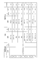
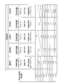
- 4 is a table showing examples of sublimable substances, solvents, and surfactants contained in a treatment liquid;
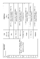
- 4 is a table showing examples of sublimable substances, solvents, and surfactants contained in a treatment liquid;
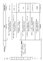
- 4 is a table showing examples of sublimable substances, solvents, and surfactants contained in a treatment liquid;
- 4 is a table showing examples of sublimable substances, solvents, and surfactants contained in a treatment liquid;
- 4 is a table showing examples of sublimable substances, solvents, and surfactants contained in a treatment liquid;
- 4 is a table showing examples of sublimable substances, solvents, and surfactants contained in a treatment liquid;
- 4 is a table showing examples of sub
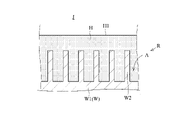
- FIG. 10 is a diagram schematically showing the substrate in the treatment liquid supply step;
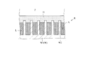
- FIG. 4 is a diagram schematically showing a substrate in a solidified film forming step;
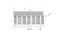
- FIG. 4 is a diagram schematically showing a substrate in a solidified film forming step; It is a figure which shows typically the board
- 4 is a table showing the evaluation of each substrate processed according to Experimental Examples 1 and 2 and Comparative Examples 1-3. It is a figure explaining the mechanism of collapse of a pattern. It is a figure explaining the mechanism of collapse of a pattern. It is a figure explaining the mechanism of collapse of a pattern. It is a figure explaining the mechanism of collapse of a pattern.
- FIG. 10 is a diagram showing configurations of a processing unit and a processing liquid generation unit according to a second embodiment
- FIG. 1 is a plan view showing the inside of the substrate processing apparatus of the first embodiment.
- the substrate processing apparatus 1 processes a substrate W. As shown in FIG.
- the processing performed on the substrate W includes a drying process.
- the substrate W is, for example, a semiconductor wafer, a liquid crystal display substrate, an organic EL (Electroluminescence) substrate, an FPD (Flat Panel Display) substrate, an optical display substrate, a magnetic disk substrate, an optical disk substrate, or a magneto-optical disk substrate. , photomask substrates, and solar cell substrates.
- the substrate W has a thin flat plate shape.
- the substrate W has a substantially circular shape in plan view.
- the substrate processing apparatus 1 includes an indexer section 3 and a processing block 7.
- a processing block 7 is connected to the indexer section 3 .
- the indexer unit 3 supplies substrates W to the processing block 7 .
- the processing block 7 performs processing on the substrate W.
- FIG. The indexer section 3 retrieves the substrates W from the processing block 7 .
- the direction in which the indexer unit 3 and the processing blocks 7 are arranged is called the "front-back direction X".
- the front-rear direction X is horizontal.
- the direction from the processing block 7 to the indexer unit 3 is called “forward”.
- the direction opposite to forward is called “backward”.
- a horizontal direction orthogonal to the front-rear direction X is called a “width direction Y”.
- One direction of the "width direction Y" is appropriately called “right side”.
- the direction opposite to right is called “left”.
- a direction perpendicular to the horizontal direction is called a “vertical direction Z”.
- front, rear, right, left, top, and bottom are indicated as appropriate for reference.
- the indexer section 3 includes a plurality of (for example, four) carrier placement sections 4 .
- Each carrier mounting portion 4 mounts one carrier C thereon.
- a carrier C accommodates a plurality of substrates W.
- Carrier C is, for example, FOUP (Front Opening Unified Pod), SMIF (Standard Mechanical Interface), and OC (Open Cassette).
- the indexer section 3 has a transport mechanism 5 .
- the transport mechanism 5 is arranged behind the carrier placement section 4 .
- the transport mechanism 5 transports the substrate W. As shown in FIG.
- the transport mechanism 5 can access the carrier C placed on the carrier placement section 4 .
- the transport mechanism 5 includes a hand 5a and a hand driving section 5b.
- the hand 5a supports the substrate W.
- the hand driving section 5b is connected to the hand 5a.
- the hand driving section 5b moves the hand 5a.
- the hand drive unit 5b moves the hand 5a in the front-rear direction X, the width direction Y, and the vertical direction Z, for example.
- the hand drive unit 5b rotates the hand 5a in a horizontal plane, for example.
- the processing block 7 has a transport mechanism 8 .
- the transport mechanism 8 transports the substrate W. As shown in FIG.
- the transport mechanism 8 and the transport mechanism 5 can transfer substrates W to each other.
- the transport mechanism 8 includes a hand 8a and a hand driving section 8b.
- the hand 8a supports the substrate W.
- the hand driving section 8b is connected to the hand 8a.
- the hand driving section 8b moves the hand 8a.
- the hand drive unit 8b moves the hand 8a in the front-rear direction X, the width direction Y, and the vertical direction Z, for example.
- the hand driving section 8b rotates the hand 8a in a horizontal plane, for example.
- the processing block 7 includes a plurality of processing units 11. Each processing unit 11 is arranged on the side of the transport mechanism 8 . Each processing unit 11 processes the substrate W. FIG.
- the processing unit 11 includes a substrate holding section 13 .
- the substrate holding part 13 holds the substrate W. As shown in FIG.
- the transport mechanism 8 can access each processing unit 11 .
- the transport mechanism 8 can transfer the substrate W to the substrate holder 13 .
- the transport mechanism 8 can take the substrate W from the substrate holder 13 .
- FIG. 2 is a control block diagram of the substrate processing apparatus 1.
- the substrate processing apparatus 1 includes a control section 10 .
- the controller 10 controls the transport mechanisms 5 and 8 and the processing unit 11 .
- the control unit 10 is realized by a central processing unit (CPU) that executes various processes, a RAM (Random-Access Memory) that serves as a work area for arithmetic processing, a storage medium such as a fixed disk, and the like.
- the control unit 10 has various types of information stored in advance in a storage medium.
- Information held by the control unit 10 is, for example, transport information for controlling the transport mechanisms 5 and 8 .
- the information held by the control unit 10 is, for example, processing information for controlling the processing unit 11 . Processing information is also called a processing recipe.
- the indexer section 3 supplies substrates W to the processing block 7 .
- the transport mechanism 5 transfers the substrate W from the carrier C to the transport mechanism 8 of the processing block 7 .
- the processing block 7 distributes the substrates W from the indexer section 3 to the processing units 11 .
- the transport mechanism 8 transports the substrate W from the transport mechanism 5 to the substrate holder 13 of each processing unit 11 .
- the processing unit 11 processes the substrate W held by the substrate holding section 13 .
- the processing unit 11 performs a drying process on the substrate W, for example.
- the processing block 7 After the processing unit 11 processes the substrate W, the processing block 7 returns the substrate W from the processing unit 11 to the indexer section 3 . Specifically, the transport mechanism 8 transports the substrate W from the substrate holder 13 to the transport mechanism 5 .
- the indexer section 3 recovers the substrates W from the processing block 7 .
- the transport mechanism 5 transports the substrate W from the transport mechanism 8 to the carrier C. As shown in FIG.
- FIG. 3 is a diagram showing the configuration of the processing unit 11. As shown in FIG. Each processing unit 11 has the same structure. The processing unit 11 is classified as a single wafer type. That is, each processing unit 11 processes only one substrate W at a time.
- the substrate holding part 13 holds one substrate W.
- the substrate holding part 13 holds the substrate W in a substantially horizontal posture.
- the substrate holding part 13 holds the peripheral portion of the substrate W or the lower surface of the substrate W.
- the bottom surface of the substrate W is also called the backside of the substrate W. As shown in FIG.
- the processing unit 11 includes a rotation drive section 14 .
- the rotation driving section 14 is connected to the substrate holding section 13 .
- the rotation driving section 14 rotates the substrate holding section 13 .
- the substrate W held by the substrate holding portion 13 rotates together with the substrate holding portion 13 .
- the substrate W held by the substrate holding part 13 rotates around the rotation axis B.
- the rotation axis B extends in the vertical direction Z through the center of the substrate W, for example.
- the processing unit 11 includes a first nozzle 15a, a second nozzle 15b, a third nozzle 15c, a fourth nozzle 15d and a fifth nozzle 15e.
- the first to fifth nozzles 15a to 15e are simply referred to as "nozzles 15" when not distinguished from each other.
- Each nozzle 15 ejects liquid or gas onto the substrate W, respectively. More specifically, each nozzle 15 ejects liquid or gas onto the upper surface W1 of the substrate W held by the substrate holder 13 .
- Each nozzle 15 is movable between a processing position and a standby position.
- the processing position is, for example, a position above the substrate W held by the substrate holding part 13 .
- the standby position is, for example, a position away from above the substrate W held by the substrate holding part 13 .
- the processing unit 11 has a housing 16 .
- the housing 16 has a substantially box shape.
- the housing 16 accommodates the substrate holding section 13 , the rotation driving section 14 and the nozzle 15 inside the housing 16 .
- the substrate W is processed inside the housing 16 .
- the inside of the housing 16 is kept at room temperature.
- the inside of the housing 16 is kept at normal pressure. Therefore, the substrate W is processed under an environment of room temperature and normal pressure.
- the room temperature is, for example, a temperature within the range of 10° C. or higher and 35° C. or lower.
- Room temperature is, for example, a temperature within the range of 20° C. or higher and 30° C. or lower.
- Normal pressure includes standard atmospheric pressure (1 atmosphere, 1013 hPa). Normal pressure is, for example, an atmospheric pressure in the range of 0.7 atmospheres or more and 1.3 atmospheres or less. Pressure is indicated herein in terms of absolute pressure relative to absolute vacuum.
- the processing unit 11 may further include a cup (not shown).
- the cup is installed inside the housing 16 .
- the cup is arranged around the substrate holder 13 .
- the cup receives the liquid scattered from the substrate W held by the substrate holding part 13 .
- the processing unit 11 includes pipes 17a, 17b, 17c, 17d, and 17e.
- the pipes 17a-17e are connected to the first to fifth nozzles 15a-15e, respectively. At least part of the pipe 17 a may be provided outside the housing 16 . Lines 17b-17e may also be arranged similarly to line 17a.
- the processing unit 11 includes valves 18a, 18b, 18c, 18d, and 18e.
- Valves 18a-18e are provided in lines 17a-17e, respectively.
- the valve 18 a may be provided outside the housing 16 .
- Valves 18b-18e may also be arranged similarly to valve 18a.
- the substrate processing apparatus 1 includes a processing liquid generation unit 20 .
- the treatment liquid generation unit 20 is connected to the pipe 17a.
- the processing liquid generation unit 20 is connected to the first nozzle 15a through a pipe 17a.
- the treatment liquid generation unit 20 communicates with the first nozzle 15a.
- the processing liquid generation unit 20 generates processing liquid.
- the treatment liquid generation unit 20 sends the treatment liquid to the first nozzle 15a.
- the first nozzle 15a ejects the treatment liquid.
- the processing liquid generation unit 20 may supply the processing liquid to a plurality of processing units 11 .
- the first nozzle 15a is an example of a processing liquid supply section in the present invention.
- the pipe 17b is connected to the chemical supply source 19b.
- the chemical supply source 19b is connected to the second nozzle 15b.
- the chemical liquid supply source 19b sends the chemical liquid to the second nozzle 15b.
- the second nozzle 15b ejects the chemical liquid.
- the chemical solution is, for example, an etchant.
- the chemical solution contains, for example, at least one of hydrofluoric acid (HF) and buffered hydrofluoric acid (BHF).
- HF hydrofluoric acid
- BHF buffered hydrofluoric acid
- the pipe 17c is connected to the rinse liquid supply source 19c.
- the rinse liquid supply source 19c is connected to the third nozzle 15c.
- the rinse liquid supply source 19c sends the rinse liquid to the third nozzle 15c.
- the third nozzle 15c ejects the rinse liquid.
- the rinse liquid is, for example, deionized water (DIW).
- the pipe 17d is connected to the replacement liquid supply source 19d.
- the substitution liquid supply source 19d is connected to the fourth nozzle 15d.
- a substitute liquid supply source 19d delivers a substitute liquid to the fourth nozzle 15d.
- the fourth nozzle 15d ejects replacement liquid.
- the replacement liquid is, for example, an organic solvent.
- the replacement liquid is, for example, isopropyl alcohol (IPA).
- the pipe 17e is connected to the gas supply source 19e.
- the gas supply source 19e is communicatively connected to the fifth nozzle 15e.
- a gas supply source 19e delivers gas to the fifth nozzle 15e.
- the fifth nozzle 15e ejects gas.
- the fifth nozzle 15e blows off gas.
- the gas is, for example, dry gas.
- a dry gas has a dew point below room temperature. The dew point is, for example, about -76°C. Therefore, dry gas does not condense at room temperature.
- Gas is air, for example.
- the gas is, for example, compressed air.
- a gas is, for example, an inert gas.
- the gas is, for example, nitrogen gas.
- the fifth nozzle 15e is an example of a gas supply section in the present invention.
- the chemical supply source 19b may be an element of the substrate processing apparatus 1.
- the chemical liquid supply source 19b may be a chemical liquid tank included in the substrate processing apparatus 1 .
- the chemical supply source 19b may not be a component of the substrate processing apparatus 1.
- the chemical supply source 19b may be utility equipment installed outside the substrate processing apparatus 1 .
- the rinsing liquid supply source 19c, the replacement liquid supply source 19d, and the gas supply source 19e may or may not be elements of the substrate processing apparatus 1, respectively.
- the controller 10 controls the rotary drive 14 and the valves 18a-18e.
- the treatment liquid generated by the treatment liquid generation unit 20 will be described.
- the treatment liquid contains a sublimable substance, a solvent and a surfactant.
- the treatment liquid consists of, for example, only a sublimable substance, a solvent, and a surfactant.
- condition E1 The sublimable substance has sublimability.
- Condition E2 The sublimable substance is solid at room temperature.
- Condition E3 The sublimable substance is soluble in the solvent at room temperature.
- Condition E4 The sublimable substance has a vapor pressure of 0.01 Pa (absolute pressure) or more at room temperature.
- "sublimability” is the property of a single substance, compound, or mixture undergoing a phase transition from solid to gas or from gas to solid without passing through liquid.
- the sublimable substance can remain solid over the temperature range specified at room temperature.
- the solvent is liquid at room temperature.
- the solvent dissolves the sublimable substance.
- the sublimable substance in the treatment liquid is dissolved in the solvent. That is, the treatment liquid contains a solvent, a sublimable substance dissolved in the solvent, and a surfactant.
- the volume of the sublimable substance contained in the treatment liquid is smaller than the volume of the solvent contained in the treatment liquid.
- the volume of the sublimable substance contained in the treatment liquid is preferably 1% or more of the volume of the solvent contained in the treatment liquid and 10% or less of the volume of the solvent contained in the treatment liquid.
- the volume of the surfactant contained in the treatment liquid is smaller than the volume of the solvent contained in the treatment liquid.
- the volume of the surfactant contained in the treatment liquid is preferably 0.01% or more of the volume of the solvent contained in the treatment liquid and 10% or less of the volume of the solvent contained in the treatment liquid.
- the surfactant and solvent in the treatment liquid preferably satisfy the following relationship.
- the group of compounds that can be selected as a solvent and the group of compounds that can be selected as a surfactant may overlap each other. However, it is prohibited to select the same compound as solvent and surfactant at the same time. It is prohibited to select compounds with the same composition as solvent and surfactant at the same time.
- methanol belongs to the group of compounds that can be selected as a solvent and belongs to the group of compounds that can be selected as a surfactant.
- methanol may be selected as the solvent and also as the surfactant.
- the surfactant does not contain methanol. That is, when the solvent contains methanol, the surfactant is prohibited from containing methanol.
- the surfactant may contain methanol when the solvent does not contain methanol. That is, it is permissible for the surfactant to contain methanol when the solvent does not contain methanol.
- the treatment liquid satisfies the following first condition F1 and second condition F2. Specifically, the surfactant and solvent contained in the treatment liquid satisfy the first condition F1 and the second condition F2.
- First condition F1 The octanol/water partition coefficient LogPow of the surfactant is -1 or more and 1 or less.
- Second condition F2 The vapor pressure Pc of the surfactant at room temperature is 0.9 times or more the vapor pressure Pb of the solvent at room temperature, and 3 times or less than the vapor pressure Pb of the solvent at room temperature.
- the treatment liquid preferably satisfies the following third condition F3.
- the solvent and the sublimable substance contained in the treatment liquid preferably satisfy the third condition F3.
- Third condition F3 The vapor pressure Pb of the solvent at room temperature is higher than the vapor pressure Pa of the sublimable substance at room temperature.
- the treatment liquid preferably satisfies the following fourth condition.
- the surfactant and sublimation substance contained in the treatment liquid preferably satisfy the fourth condition F4.
- Fourth condition F4 The vapor pressure Pc of the surfactant at room temperature is higher than the vapor pressure Pa of the sublimable substance at room temperature.
- FIGS. 4-11 are tables respectively exemplifying sublimable substances, solvents, and surfactants contained in the treatment liquid.
- 1-78 indicates the number of the treatment liquid. No. 1-78 each satisfy the first condition F1 and the second condition F2. No. shown in Fig. 4-11. Each of the treatment liquids of 1-78 further satisfies the third condition F3. No. shown in Fig. 4-11. Each of the treatment liquids of 1-78 further satisfies the fourth condition F4.
- the sublimable substance is cyclohexanone oxime.
- the solvent and surfactant are any one of a1)-a20) below.
- No. The treatment liquid of No. 1 corresponds to a treatment liquid containing cyclohexanone oxime, a solvent and a surfactant defined in a1).
- no. 1 treatment liquid contains cyclohexanone oxime and contains the solvent and surfactant defined in a1).
- no. The treatment liquids of 2-20 respectively correspond to treatment liquids containing cyclohexanone oxime and solvents and surfactants defined in a2)-a20).
- the solvent is methanol and the surfactant is acetone.
- a2) the solvent is ethanol and the surfactant is methanol;
- a3) The solvent is isopropyl alcohol (IPA) and the surfactant is methanol.
- IPA isopropyl alcohol
- IPA isopropyl alcohol
- IPA isopropyl alcohol
- a6 The solvent is tert-butanol and the surfactant is methanol.
- the solvent is tert-butanol and the surfactant is ethanol.
- the solvent is tert-butanol and the surfactant is ethanol.
- a8) The solvent is tert-butanol and the surfactant is is isopropyl alcohol (IPA).
- the solvent is 1-propanol and the surfactant is ethanol. a10) The solvent is 1-propanol and the surfactant is isopropyl alcohol (IPA). a11) The solvent is 1-propanol and the surfactant is tert-butanol. a12) The solvent is isobutanol and the surfactant is 1-propanol. a13) The solvent is 1-ethoxy-2-propanol (PGEE) and the surfactant is 1-propanol. a14) The solvent is 1-ethoxy-2-propanol (PGEE) and the surfactant is isobutanol. a15) The solvent is 1-butanol and the surfactant is 1-propanol.
- IPA isopropyl alcohol
- the solvent is 1-butanol and the surfactant is isobutanol. a17) The solvent is 1-butanol and the surfactant is 1-ethoxy-2-propanol (PGEE). a18) The solvent is propylene glycol monomethyl ether acetate (PGMEA) and the surfactant is isobutanol. a19) The solvent is propylene glycol monomethyl ether acetate (PGMEA) and the surfactant is 1-ethoxy-2-propanol (PGEE). a20) The solvent is propylene glycol monomethyl ether acetate (PGMEA) and the surfactant is 1-butanol.
- Figures 4 and 5 show the vapor pressure Pa of the sublimable substance at room temperature. 4 and 5 show the vapor pressure Pb of the solvent at room temperature. Figures 4 and 5 show the surfactant vapor pressure Pc at room temperature. Figures 4 and 5 show the octanol/water partition coefficient LogPow of surfactants. 4 and 5 show the value G obtained by dividing the vapor pressure Pc by the vapor pressure Pb.
- the measurement temperature of the vapor pressure Pa of cyclohexanone oxime is 25 degrees.
- the temperature at which the vapor pressures Pb and Pc of PGEE are measured is 25 degrees.
- the temperature at which the vapor pressure Pb of solvents other than PGEE is measured is 20 degrees.
- the measurement temperature of the vapor pressure Pc of surfactants other than PGEE is 20 degrees.
- the octanol/water partition coefficient LogPow of the surfactant is greater than or equal to ⁇ 1 and less than or equal to 1. That is, the octanol/water partition coefficient LogPow of the surfactant is -1 or more and 1 or less, regardless of which surfactant is a1) to a20). Therefore, No.
- Each of the treatment liquids 1-20 satisfies the first condition F1.
- the value G is 0.9 or more and 3 or less in the treatment liquid of 1-20. That is, the vapor pressure Pc of the surfactant is 0.9 times or more and 3 times or less the vapor pressure Pb of the solvent, regardless of whether the solvent and the surfactant are a1) to a20). Therefore, No.
- Each of the treatment liquids 1-20 satisfies the second condition F2.
- the vapor pressure Pb of the solvent is higher than the vapor pressure Pa of cyclohexanone oxime. That is, the vapor pressure Pb of the solvent is higher than the vapor pressure Pa of cyclohexanone oxime, regardless of which solvent is a1) to a20). Therefore, No.
- Each of the treatment liquids 1-20 satisfies the third condition F3.
- the vapor pressure Pc of the surfactant is higher than the vapor pressure Pa of cyclohexanone oxime. That is, the vapor pressure Pc of the surfactant is higher than the vapor pressure Pa of cyclohexanone oxime regardless of which surfactant is a1) to a20). Therefore, No.
- Each of the treatment liquids 1-20 satisfies the fourth condition F4.
- the sublimable substance is camphor.
- the solvent and surfactant are any one of a1)-a20) above.
- No. The treatment liquid of No. 21 corresponds to a treatment liquid containing camphor, a solvent and a surfactant as defined in a1).
- no. The treatment liquid of 21 contains camphor and contains the solvent and surfactant defined in a1).
- no. Treatment liquids 22-40 correspond to treatment liquids containing camphor and solvents and surfactants defined in a2)-a20), respectively.
- Figures 6 and 7 show the vapor pressure Pa of camphor at room temperature.
- the temperature at which the vapor pressure Pa of camphor is measured is 25 degrees.
- the octanol/water partition coefficient LogPow of the surfactant is -1 or more and 1 or less, regardless of which surfactant is a1)-a20). For this reason, No. In the treatment liquid No. 21-40, the octanol/water partition coefficient LogPow of the surfactant is -1 or more and 1 or less. Therefore, No. Each of the treatment liquids 21-40 satisfies the first condition F1.
- the vapor pressure Pc of the surfactant is 0.9 times or more and 3 times or less the vapor pressure Pb of the solvent. .
- the vapor pressure Pc of the surfactant is 0.9 times or more and 3 times or less the vapor pressure Pb of the solvent. Therefore, No.
- the treatment liquids 21-40 each satisfy the second condition F2.
- the vapor pressure Pb of the solvent is higher than the vapor pressure Pa of camphor. That is, the vapor pressure Pb of the solvent is higher than the vapor pressure Pa of camphor regardless of which solvent is a1)-a20). Therefore, No. 21 to 40 each satisfy the third condition F3.
- the vapor pressure Pc of the surfactant is higher than the vapor pressure Pa of camphor. That is, the vapor pressure Pc of the surfactant is higher than the vapor pressure Pa of camphor regardless of whether the surfactant is a1)-a20). Therefore, No. 21 to 40 each satisfy the fourth condition F4.
- the sublimable substance is ⁇ -caprolactam.
- the solvent and surfactant are any one of a1)-a20) above.
- the treatment liquid of 41 corresponds to a treatment liquid containing ⁇ -caprolactam and the solvent and surfactant specified in a1). In other words, no. The treatment liquid of 41 contains ⁇ -caprolactam and contains the solvent and surfactant defined in a1). Similarly, no. The processing liquids of 42-60 correspond to processing liquids containing ⁇ -caprolactam and the solvents and surfactants specified in a2)-a20) respectively.
- Figures 8 and 9 show the vapor pressure Pa of ⁇ -caprolactam at room temperature.
- the temperature at which the vapor pressure Pa of ⁇ -caprolactam is measured is 25 degrees.
- the octanol/water partition coefficient LogPow of the surfactant is -1 or more and 1 or less, regardless of which surfactant is a1)-a20). For this reason, No.
- the octanol/water partition coefficient LogPow of the surfactant is -1 or more and 1 or less even in the treatment liquid of 41-60. Therefore, No.
- the treatment liquids 41-60 each satisfy the first condition F1.
- the vapor pressure Pc of the surfactant is 0.9 times or more and 3 times or less the vapor pressure Pb of the solvent. .
- the vapor pressure Pc of the surfactant is 0.9 times or more and 3 times or less the vapor pressure Pb of the solvent. Therefore, No.
- the treatment liquids 41-60 each satisfy the second condition F2.
- the vapor pressure Pb of the solvent is higher than the vapor pressure Pa of ⁇ -caprolactam. That is, the vapor pressure Pb of the solvent is higher than the vapor pressure Pa of ⁇ -caprolactam, regardless of which solvent is a1) to a20). Therefore, No.
- the treatment liquids 41-60 each satisfy the third condition F3.
- the vapor pressure Pc of the surfactant is higher than the vapor pressure Pa of ⁇ -caprolactam. That is, the vapor pressure Pc of the surfactant is higher than the vapor pressure Pa of ⁇ -caprolactam regardless of which surfactant is a1) to a20). Therefore, No.
- the treatment liquids 41-60 each satisfy the fourth condition F4.
- FIG. 10 shows No. 61-69 are shown.
- Sublimable substances are, for example, cyclohexanone oxime, camphor and/or ⁇ -caprolactam.
- Solvents and surfactants are any one of b1)-b9) below.
- No. The processing liquid of 61 corresponds to a processing liquid containing a sublimable substance, a solvent and a surfactant defined in b1).
- the treatment liquid of 61 contains at least one of cyclohexanone oxime, camphor and ⁇ -caprolactam, and also contains the solvent and surfactant defined in b1).
- the processing liquids of 62-69 respectively correspond to processing liquids containing sublimable substances, solvents and surfactants defined in b2)-b9).
- Solvents and surfactants are any one of b1)-b9) below.
- b1) The solvent is methanol and the surfactant is acetone.
- b2) the solvent is ethanol and the surfactant is methanol;
- b3) The solvent is isopropyl alcohol (IPA) and the surfactant is at least one of methanol, ethanol and tert-butanol.
- IPA isopropyl alcohol
- the solvent is tert-butanol and the surfactant is at least one of methanol, ethanol and isopropyl alcohol (IPA).
- IPA isopropyl alcohol
- IPA isopropyl alcohol
- the solvent is isobutanol and the surfactant is 1-propanol
- the solvent is 1-ethoxy-2-propanol (PGEE) and the surfactant is 1-propanol and isobutanol At least one.
- the solvent is 1-butanol and the surfactant is at least one of 1-propanol, isobutanol and 1-ethoxy-2-propanol (PGEE).
- the solvent is propylene glycol monomethyl ether acetate (PGMEA), and the surfactant is at least one of isobutanol, 1-ethoxy-2-propanol (PGEE) and 1-butanol.
- M is at least one of Ma, Mb and Mc
- M is at least one of Ma, Mb and Mc
- M is at least one of Ma, Mb and Mc
- M is, for example, a sublimable substance, a solvent, or a surfactant.
- Ma, Mb and Mc are names of compounds respectively.
- the solvent in b3) is the same as the solvent in a3)-a5).
- the surfactant of b3) is at least one of the surfactants of a3)-a5).
- No. The treatment liquid No. 63 satisfies the first to fourth conditions F1 to F4.
- No. The treatment liquids 64, 65, 67-69 satisfy the first to fourth conditions F1 to F4, respectively.
- FIG. 11 shows No. 70-78 processing solutions are shown.
- Sublimable substances are, for example, cyclohexanone oxime, camphor and/or ⁇ -caprolactam.
- Solvents and surfactants are any one of c1)-c9) below.
- No. The processing liquid of 70 corresponds to a processing liquid containing a sublimable substance, a solvent and a surfactant defined in c1).
- the treatment liquid of 70 contains at least one of cyclohexanone oxime, camphor and ⁇ -caprolactam, and also contains the solvent and surfactant defined in c1).
- the processing liquids of 71-78 respectively correspond to processing liquids containing a sublimable substance and solvents and surfactants defined in c2)-c9).
- Solvents and surfactants are any one of c1)-c9) below.
- c1) The solvent is methanol and the surfactant is acetone.
- c2) The solvent is at least one of ethanol, isopropyl alcohol (IPA) and tert-butanol, and the surfactant is methanol.
- c3) The solvent is at least one of isopropyl alcohol (IPA), tert-butanol and 1-propanol, and the surfactant is ethanol.
- the solvent is at least one of isopropyl alcohol (IPA) and 1-propanol, and the surfactant is tert-butanol.
- the solvent is at least one of tert-butanol and 1-propanol, and the surfactant is isopropyl alcohol (IPA).
- the solvent is at least one of isobutanol, 1-ethoxy-2-propanol (PGEE) and 1-butanol, and the surfactant is 1-propanol.
- the solvent is at least one of 1-ethoxy-2-propanol (PGEE), 1-butanol and propylene glycol monomethyl ether acetate (PGMEA), and the surfactant is isobutanol.
- the solvent is at least one of 1-butanol and propylene glycol monomethyl ether acetate (PGMEA), and the surfactant is 1-ethoxy-2-propanol (PGEE).
- the solvent is propylene glycol monomethyl ether acetate (PGMEA) and the surfactant is 1-butanol.
- c1) is the same as a1). For this reason, No. 70 of the treatment liquid satisfies the first to fourth conditions F1 to F4. For the same reason, No. Each of the 78 treatment liquids satisfies the first to fourth conditions F1 to F4.
- the surfactant of c2) is the same as the surfactants of a2), a3) and a6).
- the solvent of c2) is at least one of the solvents of a2), a3) and a6).
- the processing liquid generation unit 20 generates a processing liquid containing a sublimation substance, a solvent and a surfactant.
- the treatment liquid generation unit 20 includes a first tank 21 .
- the first tank 21 communicates with the first nozzle 15a.
- the first tank 21 is connected to the first nozzle 15a.
- the processing liquid generation unit 20 generates the processing liquid in the first tank 21 .
- the processing liquid is generated under a room temperature environment.
- the processing liquid is generated under a normal pressure environment.
- the processing liquid generating unit 20 stores the generated processing liquid in the first tank 21 .
- the processing liquid is stored under a room temperature environment.
- the processing liquid is stored under normal pressure environment.
- the treatment liquid generation unit 20 includes a sublimable substance supply section 23 , a solvent supply section 25 and a surfactant supply section 27 .
- the sublimable substance supply unit 23 supplies the sublimable substance to the first tank 21 .
- the solvent supply unit 25 supplies the solvent to the first tank 21 .
- the surfactant supply unit 27 supplies surfactant to the first tank 21 .
- the sublimable substance, solvent and surfactant are mixed in the first tank 21 . Thereby, a treatment liquid containing a sublimable substance, a solvent, and a surfactant is generated.
- the sublimable substance supply unit 23 includes, for example, a pipe 23a and a valve 23b.
- the pipe 23 a communicates with the first tank 21 .
- the pipe 23 a is connected to the first tank 21 .
- the pipe 23 a further communicates with a sublimable substance supply source 24 .
- the pipe 23 a is connected to the sublimable substance supply source 24 .
- the valve 23b is provided on the pipe 23a. When the valve 23b is opened, the pipe 23a supplies the sublimable substance from the sublimable substance supply source 24 to the first tank 21. As shown in FIG.
- the solvent supply unit 25 includes, for example, a pipe 25a and a valve 25b.
- the pipe 25 a communicates with the first tank 21 .
- the pipe 25 a is connected to the first tank 21 .
- the pipe 25 a also communicates with a solvent supply source 26 .
- the pipe 25 a is connected to a solvent supply source 26 .
- the valve 25b is provided on the pipe 25a. When valve 25b opens, line 25a supplies solvent from solvent supply 26 to first tank 21 .
- the surfactant supply unit 27 includes, for example, a pipe 27a and a valve 27b.
- the pipe 27 a communicates with the first tank 21 .
- the pipe 27 a is connected to the first tank 21 .
- the pipe 27a also communicates with a surfactant supply source 28 .
- the pipe 27 a is connected to a surfactant supply source 28 .
- the valve 27b is provided on the pipe 27a. When valve 27b is open, line 27a supplies surfactant from surfactant supply 28 to first tank 21 .
- the treatment liquid generation unit 20 includes at least one or more (for example, two) first sensors 29 .
- the first sensor 29 detects the amount of processing liquid stored in the first tank 21 .
- the first sensor 29 is attached to the first tank 21, for example.
- the first sensor 29 detects, for example, the height position of the liquid surface of the processing liquid stored in the first tank 21 .
- the first sensor 29 is, for example, a liquid level sensor.
- the treatment liquid generation unit 20 further sends the treatment liquid to the first nozzle 15a.
- the treatment liquid generation unit 20 includes a liquid sending section 31 .
- the liquid sending unit 31 sends the treatment liquid from the first tank 21 to the first nozzle 15a.
- the liquid sending unit 31 includes a pipe 32, a pump 33, a filter 34, and a joint 35.
- the pipe 32 communicates with the first tank 21 .
- a pipe 32 is connected to the first tank 21 .
- a pipe 32 extends from the first tank 21 to the pipe 17a.
- a pump 33 is provided in the pipe 32 .
- a pump 33 sends the processing liquid from the first tank 21 to the pipe 32 .
- a filter 34 is provided in the pipe 32 .
- the filter 34 filters the processing liquid flowing through the pipe 32 . Filter 34 removes contaminants from the processing liquid.
- the joint 35 is connected to the pipe 32 .
- the joint 35 is further connected to the pipe 17a.
- the pipe 32 and the pipe 17a communicate with each other through a joint 35. As shown in FIG.
- the pipe 32 communicates with the first nozzle 15a.
- the first tank 21 is connected to the first nozzle 15a via pipes 32, 17a. Therefore, the pump 33 sends the processing liquid from the first tank 21 to the pipe
- the control section 10 controls the treatment liquid generation unit 20 .
- the control section 10 is electrically communicably connected to the treatment liquid generation unit 20 .
- the control unit 10 controls the sublimable substance supply unit 23 , the solvent supply unit 25 and the surfactant supply unit 27 .
- the control unit 10 controls the valves 23b, 25b, 27b.
- the control unit 10 acquires the detection result of the first sensor 29 .
- the control section 10 controls the liquid feeding section 31 .
- the controller 10 controls the pump 33 .
- the control unit 10 has treatment liquid generation information for controlling the treatment liquid generation unit 20 .
- the processing liquid generation information is pre-stored in the storage medium of the control unit 10 .
- the treatment liquid generation information defines, for example, the compounding ratio of the sublimation substance, solvent, and surfactant contained in the treatment liquid.
- FIG. 12 is a flow chart showing the procedure of the substrate processing method.
- the substrate processing method includes step S1 and steps S11-S18.
- Step S ⁇ b>1 is executed by the treatment liquid generation unit 20 .
- Steps S 11 -S 18 are substantially performed by processing unit 11 .
- Step S1 is executed in parallel with steps S11-S18.
- the treatment liquid generation unit 20 and the treatment unit 11 operate under the control of the controller 10 .
- Step S1 Treatment Liquid Generation Step
- the treatment liquid generation unit 20 generates a treatment liquid.
- the sublimable substance supply unit 23 supplies the sublimable substance to the first tank 21 .
- the solvent supply unit 25 supplies the solvent to the first tank 21 .
- the surfactant supply unit 27 supplies surfactant to the first tank 21 . Thereby, the treatment liquid is generated in the first tank 21 . Then, the treatment liquid is stored in the first tank 21 .
- the first sensor 29 detects the amount of processing liquid stored in the first tank 21 .
- the control unit 10 monitors the detection result of the first sensor 29 .
- the control unit 10 starts and stops the treatment liquid generation process based on the detection result of the first sensor 29 .
- the control section 10 starts the processing liquid generation step.
- the treatment liquid generation unit 20 starts to generate the treatment liquid.
- the processing liquid stored in the first tank 21 increases.
- the control section 10 stops the processing liquid generation step.
- the second threshold is greater than the first threshold.
- the processing liquid generation unit 20 stops generating the processing liquid.
- the increase of the processing liquid stored in the first tank 21 stops.
- the first threshold and the second threshold are set in advance, for example.
- the first threshold and the second threshold are defined, for example, in the treatment liquid generation information.
- Step S11 Rotation Start Step
- the substrate holder 13 holds the substrate W. As shown in FIG.
- the substrate W is held by the substrate holder 13 in a substantially horizontal posture.
- the rotation driving section 14 rotates the substrate holding section 13 .
- the substrate W held by the substrate holding part 13 starts rotating.
- Steps S12-S17 are performed with the substrate W rotated.
- Step S12 Chemical solution supply step
- the second nozzle 15b supplies the substrate W with the chemical solution.
- valve 18b opens.
- the second nozzle 15b supplies the chemical liquid to the substrate W held by the substrate holding part 13 .
- the second nozzle 15b ejects the chemical solution onto the upper surface W1 of the substrate W.
- a chemical solution is supplied to the upper surface W1 of the substrate W.
- the valve 18b is then closed.
- the second nozzle 15b stops supplying the chemical solution.
- Step S13 Rinse liquid supply step
- the third nozzle 15c supplies the substrate W with the rinse liquid.
- the valve 18c is opened.
- the third nozzle 15c supplies the rinse liquid to the substrate W held by the substrate holding part 13 .
- the third nozzle 15c ejects the rinse liquid onto the upper surface W1 of the substrate W.
- a rinse liquid is supplied to the upper surface W1 of the substrate W.
- the rinse liquid cleans the substrate W.
- FIG. The rinsing liquid removes the chemical liquid from the substrate W.
- FIG. The valve 18c is then closed.
- the third nozzle 15c stops supplying the rinse liquid.
- Step S14 Substituting Liquid Supplying Step
- the fourth nozzle 15d supplies the substrate W with the substituting liquid. Specifically, the valve 18d is opened. The fourth nozzle 15 d supplies the replacement liquid to the substrate W held by the substrate holding portion 13 . The fourth nozzle 15d ejects the replacement liquid onto the upper surface W1 of the substrate W. As shown in FIG. A replacement liquid is supplied to the upper surface W1 of the substrate W. As shown in FIG. As a result, the replacement liquid replaces the rinse liquid on the substrate W. FIG. In other words, the replacement liquid removes the rinse liquid from on the substrate W. FIG. The valve 18d is then closed. The fourth nozzle 15d stops supplying the replacement liquid.
- Step S15 Treatment liquid supply step
- the treatment liquid generation unit 20 sends the treatment liquid generated in the treatment liquid generation step to the first nozzle 15a.
- the pump 33 sends the treatment liquid from the first tank 21 to the pipe 17a.
- Valve 18a opens.
- the first nozzle 15 a supplies the processing liquid to the substrate W held by the substrate holding part 13 .
- the first nozzle 15a ejects the processing liquid onto the upper surface W1 of the substrate W.
- a processing liquid is supplied to the upper surface W1 of the substrate W.
- the replacement liquid on the substrate W is replaced with the processing liquid.
- the processing liquid removes the replacement liquid from above the substrate W.
- FIG. The pump 33 then stops.
- Valve 18a is closed.
- the first nozzle 15a stops supplying the treatment liquid.
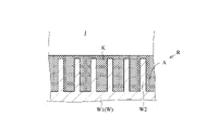
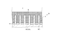
- FIG. 13 is a diagram schematically showing the substrate W in the process of supplying the processing liquid.
- the substrate W has a pattern R.
- a pattern R is formed on the surface of the substrate W. As shown in FIG.
- the pattern R is positioned on the upper surface W1 of the substrate W when the substrate W is held by the substrate holding portion 13 . When the substrate W is held by the substrate holding portion 13, the pattern R faces upward.
- the pattern R may be formed before the processing unit 11 processes the substrate W, for example.
- the pattern R may be formed by, for example, the chemical solution supply step (step S12).
- the pattern R has a convex portion W2 and a concave portion A.
- the protrusion W2 is part of the substrate W. As shown in FIG.
- the protrusion W2 is a structure.
- the protrusion W2 is composed of, for example, a silicon oxide film (SiO2), a silicon nitride film (SiN), or a polysilicon film.
- the protrusion W2 protrudes upward.
- the concave portion A is laterally adjacent to the convex portion W2.
- the recess A is a space.
- the recess A is open upward.
- the convex portion W2 corresponds to a wall that partitions the concave portion A. As shown in FIG.
- the processing liquid H is positioned on the upper surface W1 of the substrate W.
- the processing liquid H forms a film covering the upper surface W1 of the substrate W. As shown in FIG.
- the treatment liquid H has an upper surface H1.
- the upper surface H1 is positioned higher than the entire pattern R. As shown in FIG.
- the entire pattern R is immersed in the treatment liquid H.
- the upper surface H1 is positioned higher than all of the protrusions W2. All of the protrusions W2 are immersed in the treatment liquid H. As shown in FIG.
- the recess A is filled with the treatment liquid H. All of the recesses A are filled with the treatment liquid H only.
- the replacement liquid has already been removed from the upper surface W1 of the substrate W by the processing liquid H. Therefore, the replacement liquid no longer exists on the upper surface W1 of the substrate W. FIG. The replacement liquid does not remain in the recess A.
- the gas J is located above the treatment liquid H. Gas J is in contact with upper surface H1.
- the upper surface H1 corresponds to the gas-liquid interface between the processing liquid H and the gas J.
- the protrusion W2 does not contact the upper surface H1. Therefore, the treatment liquid H does not form a meniscus on the protrusion W2. Therefore, the surface tension of the treatment liquid H does not act on the protrusions W2.
- the height position of the upper surface H1 of the processing liquid H may be further adjusted.
- the height position of the upper surface H1 corresponds to the film thickness of the treatment liquid H.
- FIG. the height position of the upper surface H1 may be adjusted while the processing liquid H is supplied to the substrate W by the first nozzle 15a.
- the height position of the upper surface H1 may be adjusted after the supply of the treatment liquid H by the first nozzle 15a is stopped.
- the rotation speed of the substrate W the height position of the upper surface H1 may be adjusted.
- the height position of the upper surface H1 may be adjusted.
- Step S16 Solidified Film Forming Step
- the solvent and surfactant are each evaporated from the treatment liquid H on the substrate W1.
- Solvents and surfactants each change from a liquid to a gas.
- the solvent and surfactant are removed from the substrate W by evaporation of the solvent and surfactant, respectively.
- the sublimable substance is deposited on the substrate W by evaporation of the solvent and surfactant.
- a solidified film is formed on the substrate W. As shown in FIG. A solidified film is formed on the upper surface W1 of the substrate W. As shown in FIG.
- the solidified film contains the precipitated sublimable substance.
- the solidified film is free of solvents and surfactants.
- a solidified film is solid.
- FIG. 14 is a diagram schematically showing the substrate W in the solidified film forming step.
- the solvent and surfactant evaporate from the treatment liquid H, the sublimable substance precipitates and a solidified film K is formed.
- the solvent and surfactant contained in the processing liquid H are removed from the upper surface W1 of the substrate W, and the sublimable substance contained in the processing liquid H turns into a solidified film K.
- the treatment liquid satisfies the third condition F3. That is, the vapor pressure Pb of the solvent at room temperature is higher than the vapor pressure Pa of the sublimable substance at room temperature. Therefore, the solvent evaporates more easily than the sublimable substance. Therefore, the solidified film K is appropriately formed.
- the treatment liquid satisfies the fourth condition F4. That is, the vapor pressure Pc of the surfactant at room temperature is higher than the vapor pressure Pa of the sublimable substance at room temperature. For this reason, surfactants evaporate more easily than sublimable substances. Therefore, the solidified film K is formed more appropriately.
- the treatment liquid H gradually turns into a solidified film K.
- the upper portion of the treatment liquid H turns into the solidified film K.
- the solidified film K is formed above the upper surface H1 of the treatment liquid H.
- the solidified film K covers the upper surface H1 of the processing liquid H.
- the height position of the upper surface H1 of the processing liquid H gradually decreases.
- the remaining treatment liquid H is positioned below the solidified film K. As shown in FIG.
- the upper surface H1 of the processing liquid H does not come into contact with the gas J. That is, the treatment liquid H does not come into contact with the gas J.
- the gas-liquid interface between the processing liquid H and the gas J disappears.
- the upper surface H1 is in contact with the solidified film K.
- the gas J is in contact with the solidified film K. Therefore, in the solidified film forming step, the treatment liquid H decreases without exerting a significant force on the protrusions W2.
- the solvent and surfactant each leave the substrate W without exerting any significant force on the protrusions W2.
- FIG. 15 is a diagram schematically showing the substrate W in the solidified film forming step.
- the processing liquid H disappears from the substrate W.
- FIG. No liquid is present on the upper surface W1 of the substrate W.
- the recess A is filled with the solidified film K. As shown in FIG. All of the recesses A are filled with the solidified film K only. No liquid is present in the recess A.
- the pattern R is in contact with the solidified film K. As shown in FIG. Pattern R does not come into contact with liquid.
- the convex portion W2 is in contact with the solidified film K. As shown in FIG. The protrusion W2 does not come into contact with the liquid.
- Step S17 Sublimation Process
- the solidified film K is sublimated. Specifically, valve 18e is opened.
- the fifth nozzle 15 e supplies gas to the substrate W held by the substrate holding part 13 .
- the fifth nozzle 15e blows gas toward the upper surface W1 of the substrate W.
- the fifth nozzle 15e supplies gas to the solidified film K on the substrate W.
- the solidified film K sublimates.
- the solidified film K changes from solid to gas without passing through liquid.
- the solidified film K is removed from the substrate W by the sublimation of the solidified film K.
- the valve 18e is then closed.
- the fifth nozzle 15e stops supplying gas.
- FIG. 16 is a diagram schematically showing the substrate W in the sublimation process. As the solidified film K sublimates, the solidified film K gradually decreases and the gas J enters the recess A.
- the solidified film K When the solidified film K sublimates, the solidified film K does not change into a liquid. Therefore, no liquid exists on the upper surface W1 of the substrate W in the sublimation process. No liquid is present in the recess A. Pattern R does not come into contact with liquid. The protrusion W2 does not come into contact with the liquid. The solidified film K leaves the upper surface W1 of the substrate W without exerting any significant force on the protrusions W2.
- FIG. 17 is a diagram schematically showing the substrate W in the sublimation process. Finally, the solidified film K disappears from the upper surface W1 of the substrate W. As shown in FIG. The recess A is filled with a gas J. All of the recesses A are filled with gas J only. No liquid is present on the upper surface W1 of the substrate W. FIG. The substrate W is completely dried.
- the processing liquid supply process, the solidified film forming process, and the sublimation process described above correspond to examples of using the processing liquid.
- the processing liquid is used under a room temperature environment.
- the processing liquid is used under normal pressure environment.
- Step S ⁇ b>18 Rotation Stopping Step
- the rotation driving section 14 stops the rotation of the substrate holding section 13 .
- the substrate W held by the substrate holding part 13 stops rotating.
- the substrate W is stationary.
- the processing unit 11 finishes processing the substrate W.
- Experimental example 1 is performed under the following conditions.
- the substrate W is subjected to a series of processes including a chemical liquid supply process, a rinse liquid supply process, a replacement liquid supply process, a treatment liquid supply process, a solidified film formation process, and a sublimation process.
- the chemical liquid supply step uses hydrofluoric acid as the chemical liquid.
- the rinse liquid supply step uses deionized water (DIW) as the rinse liquid.
- DIW deionized water
- the substituting liquid supply step uses isopropyl alcohol as the substituting liquid.
- a surfactant-free liquid is produced.
- the surfactant-free liquid contains a sublimable substance and a solvent, and does not contain a surfactant.
- the surfactant-free liquid consists of, for example, only a sublimable substance and a solvent.
- the sublimable substance is cyclohexanone oxime.
- the solvent is isopropyl alcohol (IPA).
- IPA isopropyl alcohol
- the volume ratio of the sublimable substance and the solvent is as follows.
- Sublimable substance: solvent 2.5: 100 (volume ratio)
- a surfactant is added to the surfactant-free liquid to produce a treatment liquid.
- a plurality of types of treatment liquids are generated by changing the amount of surfactant added.
- the added amount T of the surfactant in the surfactant-free liquid is 0.00.
- the addition amount T of the surfactant differs among the eight types of treatment liquids.
- the addition amount T of the surfactant in each treatment liquid is 0.01, 0.05, 0.10, 0.50, 1.00, 2.00, 5.00 and 10.00, respectively.
- the surfactant is tert-butanol. Therefore, in Experimental Example 1, the treatment liquid contained cyclohexanone oxime as the sublimable substance, isopropyl alcohol (IPA) as the solvent, and tert-butanol as the surfactant.
- IPA isopropyl alcohol
- the treatment liquid of Experimental Example 1 is No. 1 shown in FIG. 5 processing liquid.
- the treatment liquid of Experimental Example 1 corresponds to a treatment liquid containing cyclohexanone oxime, and the solvent and surfactant specified in a5).
- any one type of treatment liquid was used in the treatment liquid supply process. Therefore, in Experimental Example 1, a series of processes are performed on the substrate W by the number of types of processing liquids. Then, a plurality of substrates W subjected to a series of treatments were obtained for each type of treatment liquid.
- a surfactant-free liquid was used instead of the processing liquid, and the substrate W was subjected to a series of processes.
- Experimental example 2 is performed under the following conditions.
- the surfactant is methanol. Other than this, it is the same as Experimental Example 1.
- the treatment liquid of Experimental Example 2 is No. 1 shown in FIG. 3 processing liquid.
- the treatment liquid of Experimental Example 2 corresponds to a treatment liquid containing cyclohexanone oxime, and the solvent and surfactant defined in a3).
- Comparative Example 1 is executed under the following conditions.
- Surfactant is cyclohexane. Other than this, it is the same as Experimental Example 1.
- the treatment liquid of Comparative Example 1 satisfies the second, third, and fourth conditions F2, F3, and F4, but does not satisfy the first condition F1.
- the octanol/water partition coefficient LOGPow of the surfactant is greater than one. Specifically, the octanol/water partition coefficient LOGPow of cyclohexane is about 3.
- Comparative Example 2 is executed under the following conditions. Surfactant is acetone. Other than this, it is the same as Experimental Example 1.
- the treatment liquid of Comparative Example 2 satisfies the first, third, and fourth conditions F1, F3, and F4, but does not satisfy the second condition F2.
- the solvent is isopropyl alcohol (IPA) and the surfactant is acetone
- the vapor pressure Pc of the surfactant at room temperature is more than three times the vapor pressure Pb of the solvent at room temperature.
- the vapor pressure Pb of isopropyl alcohol (IPA) at room temperature is 4.4 kPa.
- the vapor pressure Pc of acetone at room temperature is 24 kPa.
- the vapor pressure Pc of acetone at room temperature is approximately five times the vapor pressure Pb of isopropyl alcohol (IPA) at room temperature.
- Comparative Example 3 is executed under the following conditions.
- the surfactant is 1-butanol. Other than this, it is the same as Experimental Example 1.
- the treatment liquid of Comparative Example 3 satisfies the first, third, and fourth conditions F1, F3, and F4, but does not satisfy the second condition F2.
- the solvent is isopropyl alcohol (IPA) and the surfactant is 1-butanol
- the vapor pressure Pc of the surfactant at room temperature is less than 0.9 times the vapor pressure Pb of the solvent at room temperature.
- the vapor pressure Pb of isopropyl alcohol (IPA) at room temperature is 4.4 kPa.
- the vapor pressure Pc of 1-butanol at room temperature is 0.7 kPa. Therefore, the vapor pressure Pc of 1-butanol at room temperature is approximately 0.2 times the vapor pressure Pb of isopropyl alcohol (IPA) at room temperature.
- Each substrate W processed in Experimental Examples 1 and 2 and Comparative Examples 1-3 is evaluated according to the following evaluation criteria.
- An observer observes the measurement points on the substrate W.
- FIG. Each measurement point is a minute area at an arbitrary position on the substrate W.
- FIG. Each measurement point is magnified 50,000 times by a scanning electron microscope.
- the observer counts the number N of protrusions W2 and the number n of collapsed protrusions W2 at each measurement point.
- the number n is less than or equal to the number N.
- Observers calculate the collapse rate at each measurement point. Furthermore, the average collapse rate is calculated for each substrate W.
- the collapse index is calculated by the following equation.
- Collapse index (Average value of collapse rate when using treatment liquid) / (Average value of collapse rate when using surfactant-free liquid)
- a collapse index of less than 1 means that the collapse rate was improved compared to the collapse rate when the surfactant-free solution was used. That is, when the collapse index is less than 1, it can be said that the collapse rate of pattern R is suppressed.
- a collapse index greater than 1 means that the collapse rate was worse than the collapse rate when the surfactant-free solution was used. That is, when the collapse index is greater than 1, it can be said that pattern R has a high collapse rate.
- FIG. 18 is a table showing the evaluation of each substrate W processed by Experimental Examples 1 and 2 and Comparative Examples 1-3. Specifically, FIG. 18 shows the relationship between the added amount T of the surfactant and the collapse index.
- the collapse index is substantially less than 1 when the additive amount T is from 0.01 vol% to 10 vol%. Therefore, in Experimental Example 1, the collapse rate of pattern R was suppressed.
- the collapse index decreases as the additive amount T increases.
- the collapse index increases as the additive amount T increases.
- the collapse index is 0.47. 0.47 is the lowest value of the collapse index in Experimental Example 1.
- the collapse index is less than 1 when the additive amount T is from 0.01 vol% to 10 vol%. Therefore, in Experimental Example 2, the collapse rate of pattern R was suppressed.
- the collapse index decreases as the additive amount T increases.
- the collapse index increases as the additive amount T increases.
- the collapse index is 0.31. 0.31 is the lowest value of the collapse index in Experimental Example 2.
- Comparative Example 1 the collapse index is remarkably large when the added amount T is more than half of the range from 0.05 vol% to 10 vol%. Therefore, in Comparative Example 1, the collapse rate of pattern R deteriorated. In Comparative Example 1, when the additive amount T is from 0.05 vol % to 10 vol %, the collapse index repeatedly fluctuates between a value less than 1 and a value significantly greater than 1.
- the collapse index is greater than 1 in most of the range of the additive amount T from 0.01 vol% to 10 vol%. Therefore, in Comparative Example 2, the collapse rate of pattern R deteriorated.
- the collapse index repeatedly fluctuates between a value less than 1 and a value greater than 1.
- the collapse index is remarkably large.
- FIG. 19 is a diagram schematically showing the substrate W in the process liquid supply process.
- FIG. 20 is a diagram schematically showing the substrate W in the solidified film forming step.
- FIG. 21 is a diagram schematically showing the substrate W in the sublimation process.
- 19-21 show the case of Comparative Example 1.
- FIGS. 19-21 show cases where the octanol/water partition coefficient LOGPow of the surfactant is greater than one.
- the treatment liquid H has strong hydrophobicity.
- the protrusion W2 is hydrophobic. Therefore, the affinity between the processing liquid H and the substrate W is excessively high. Therefore, in the process liquid supply step, the film thickness of the process liquid H formed on the substrate W tends to become excessively large. For example, the film thickness of the treatment liquid H tends to be excessively larger than the height of the pattern R. For example, the film thickness of the treatment liquid H tends to be excessively larger than the height of the protrusions W2.
- the affinity between the treatment liquid H and the substrate W is high. Therefore, it is difficult to reduce the film thickness of the treatment liquid H in the treatment liquid supply step. It is difficult to adjust the film thickness of the treatment liquid H in the treatment liquid supply step.
- the thickness of the solidified film K formed on the substrate W tends to be excessively large.
- the thickness of the solidified film K tends to be excessively larger than the height of the pattern R.
- the thickness of the solidified film K tends to be excessively larger than the height of the protrusion W2.
- the collapse rate of pattern R is considered to be high.
- the present inventors presume that this phenomenon is caused by the substitution liquid remaining in the concave portion A at the end of the processing liquid supply step.
- a possible mechanism when the octanol/water partition coefficient LOGPow of the surfactant is less than ⁇ 1 is explained below.
- FIGS. 22, 23, and 24 are diagrams explaining the collapse mechanism of pattern R, respectively.
- FIG. 22 is a diagram schematically showing the substrate W in the process liquid supply process.
- FIG. 23 is a diagram schematically showing the substrate W in the solidified film forming step.
- FIG. 24 is a diagram schematically showing the substrate W in the sublimation process.
- Figures 22-24 show cases where the octanol/water partition coefficient LOGPow of the surfactant is less than -1.
- the treatment liquid H has strong hydrophilicity.
- the protrusions W2 are hydrophobic. Therefore, the affinity between the processing liquid H and the substrate W is excessively low. Therefore, for example, it is difficult for the treatment liquid H to enter the concave portion A sufficiently.
- the processing liquid H cannot remove the replacement liquid L from the substrate W sufficiently.
- the replacement liquid L remains in the concave portion A as a liquid when the processing liquid supply process ends.
- the recess A is not entirely filled with the treatment liquid H even when the treatment liquid supply step is finished.
- the concave portion A is not entirely filled with the solidified film K alone.
- the solidified film K is not formed in the entire recess A.
- the replacement liquid L remains in the recess A as a liquid.
- the solidified film K is sublimated.
- the substitution liquid L remains in the recesses A even after the solidified film K is sublimated.
- the replacement liquid L has an upper surface L1.
- the upper surface L1 is in contact with the gas J after the solidified film K is sublimated.
- the upper surface L1 serves as a gas-liquid interface between the replacement liquid L and the gas J.
- the replacement liquid L forms a meniscus on the protrusion W2. Therefore, the surface tension of the substitution liquid L acts on the protrusion W2.
- the substitution liquid L exerts a significant force on the protrusions W2. As a result, the convex portion W2 (pattern R) collapses.
- the collapse of the pattern R is not suppressed. Rather, the collapse of pattern R is exacerbated. Therefore, when the processing liquid H does not satisfy the first condition F1, the substrate W cannot be dried properly.
- the treatment liquid H satisfies the first condition F1. Therefore, the treatment liquid H has a moderate affinity for the substrate W. As shown in FIG. Therefore, in Experimental Examples 1 and 2, the collapse rate of pattern R is suitably suppressed. That is, in Experimental Examples 1 and 2, the substrate W can be properly dried while the pattern R is protected.
- the surfactant has amphipathic properties. That is, surfactants are both hydrophobic and hydrophilic. Therefore, the surfactant has an affinity for the substrate W and an affinity for the sublimation substance. For example, the affinity between the surfactant and the substrate W is higher than the affinity between the sublimable substance and the substrate W. For example, the affinity between the surfactant and the sublimable substance is higher than the affinity between the sublimable substance and the substrate W. Therefore, the affinity between the sublimable substance and the substrate W is improved through the surfactant. As a result, the treatment liquid H has an appropriate affinity for the substrate W. FIG.
- Surfactants have excessively high vapor pressures Pc. Specifically, the vapor pressure Pc of the surfactant at room temperature is more than three times the vapor pressure Pb of the solvent at room temperature. Therefore, immediately after the processing liquid H is supplied to the substrate W in the processing liquid supply step, the surfactant starts to evaporate. The surfactant may not remain in the processing liquid H until the processing liquid H contacts the substrate W sufficiently. The surfactant may evaporate before the treatment liquid H comes into contact with the substrate W sufficiently. The affinity between the processing liquid H and the substrate W may be significantly reduced before the processing liquid H contacts the substrate W sufficiently. Therefore, the processing liquid H cannot sufficiently remove the replacement liquid L from the substrate W.
- FIG. When the processing liquid supply step is finished, the substitution liquid L remains in the recess A as a liquid. The recess A is not entirely filled with the treatment liquid H even when the treatment liquid supply step is finished.
- the concave portion A is not entirely filled with the solidified film K alone. Even at the end of the solidified film forming process, the replacement liquid L remains in the recess A as a liquid.
- the substitution liquid L remains in the recesses A even after the solidified film K is sublimated.
- the upper surface L1 serves as a gas-liquid interface between the replacement liquid L and the gas J. As shown in FIG.
- the upper surface L1 is in contact with the protrusion W2. Therefore, the surface tension of the substitution liquid L acts on the protrusion W2. As a result, the convex portion W2 (pattern R) collapses.
- FIGS. 25 and 26 are diagrams explaining the collapse mechanism of pattern R, respectively.
- FIG. 25 is a diagram schematically showing the substrate W in the solidified film forming step.
- FIG. 26 is a diagram schematically showing the substrate W in the sublimation process.
- 25-26 show the case of Comparative Example 3.
- FIG. Figures 25-26 show the case where the vapor pressure Pc of the surfactant is too low. Specifically, in FIGS. 25-26, the surfactant vapor pressure Pc at room temperature is less than 0.9 times the vapor pressure of the solvent Pb at room temperature.
- the replacement liquid L does not remain in the concave portion A at the end of the processing liquid supply process.
- the recess A is entirely filled with the processing liquid H (see FIG. 13).
- the solvent evaporates from the treatment liquid H in the solidified film forming step.
- the surfactant contained in the treatment liquid H is difficult to evaporate. This is because the vapor pressure Pc of the surfactant is too low.
- the treatment liquid H containing the surfactant remains in the recesses A even after all the solvents contained in the treatment liquid H have evaporated. As a result, the treatment liquid H remains in the concave portion A at the end of the solidified film forming process.
- the solidified film K is not formed in the entire recess A.
- the solidified film K is sublimated.
- the treatment liquid H remains in the recesses A even after the solidified film K is sublimated.
- the upper surface H1 of the treatment liquid H contacts the gas J after the solidified film K is sublimated.
- the upper surface H1 becomes a gas-liquid interface between the processing liquid H and the gas J.
- FIG. The upper surface H1 is in contact with the protrusion W2. Therefore, the treatment liquid H forms a meniscus on the protrusion W2. Therefore, the surface tension of the treatment liquid H acts on the protrusions W2.
- the treatment liquid H exerts a significant force on the protrusions W2. As a result, the convex portion W2 (pattern R) collapses.
- the collapse of the pattern R is not suppressed. Rather, the collapse of pattern R is exacerbated. Even if the vapor pressure Pc of the surfactant at room temperature is less than 0.9 times the vapor pressure Pb of the solvent at room temperature, the collapse of the pattern R is not suppressed. Rather, the collapse of pattern R is exacerbated. Therefore, when the processing liquid H does not satisfy the second condition F2, the substrate W cannot be dried properly.
- the treatment liquid H satisfies the second condition F2. Therefore, the surfactant has a moderate vapor pressure Pc. Therefore, in Experimental Examples 1 and 2, the collapse rate of pattern R is suitably suppressed. That is, in Experimental Examples 1 and 2, the substrate W can be properly dried while the pattern R is protected.
- the collapse index is substantially less than 1 even when the additive amount T is in the range of 0.1 vol % to 10 vol %. However, in Experimental Example 1, the collapse index increased as the additive amount T increased in the range of 0.1 vol % to 10 vol %. In Experimental Example 2, the collapse index is less than 1 even when the additive amount T is in the range of 1.0 vol % to 10 vol %. However, in Experimental Example 2, the collapse index increased as the additive amount T increased in the range of 1.0 vol % to 10 vol %. The inventors of the present invention conjecture that this phenomenon is caused by the liquid film of the treatment liquid H being slightly large at the end of the treatment liquid supply step. The mechanism assumed when the addition amount T is increased will be described below.
- the affinity between the treatment liquid H and the substrate W increases as the addition amount T increases. Therefore, as the addition amount T increases, the film thickness of the treatment liquid H formed in the treatment liquid supply step increases. As the addition amount T increases, the film thickness of the treatment liquid H is less likely to become thin. As a result, as the addition amount T increases, the thickness of the solidified film K formed in the solidified film forming step increases. Then, in the sublimation process, when the solidified film K is sublimated, the projections W2 (pattern R) are a little easier to collapse.
- the added amount T of the surfactant is preferably 10 vol% or less of the volume of the solvent contained in the treatment liquid H.
- the volume of the surfactant contained in the treatment liquid H is preferably 10% or less of the volume of the solvent contained in the treatment liquid H.
- the collapse of the pattern R was sufficiently suppressed even when the added amount T of the surfactant was 0.01 vol%.
- the collapse index was 0.68 when the added amount T of the surfactant was 0.01 vol %.
- the collapse index was 0.72 when the added amount T of the surfactant was 0.01 vol %.
- the added amount T of the surfactant is preferably 0.01 vol% or more of the volume of the solvent contained in the treatment liquid H.
- the volume of the surfactant contained in the treatment liquid H is preferably 0.01% or more of the volume of the solvent contained in the treatment liquid H.
- the substrate processing method includes a processing liquid supply process, a solidified film forming process, and a sublimation process.
- the processing liquid H is supplied to the substrate W.
- the treatment liquid H contains a sublimation substance, a solvent, and a surfactant.
- the solidified film forming step evaporates the solvent and surfactant from the processing liquid H on the substrate W.
- FIG. A solidified film K is formed on the substrate W in the solidified film forming step.
- the solidified film K contains a sublimable substance. In the sublimation process, the solidified film K is sublimated.
- the treatment liquid H satisfies the first condition F1.
- the octanol/water partition coefficient LOGPow of the surfactant is -1 or more and 1 or less. Therefore, the treatment liquid H has a moderate affinity for the substrate W. As shown in FIG. Therefore, the surfactant improves the affinity between the sublimable substance and the substrate W.
- the processing liquid supply step can supply the processing liquid H to the substrate W appropriately.
- the process liquid H sufficiently contacts the upper surface W1 of the substrate W.
- the processing liquid H is sufficiently blended with the upper surface W1 of the substrate W in the processing liquid supply step.
- the processing liquid H is in sufficient contact with the pattern R.
- the processing liquid H enters the recess A easily.
- the processing liquid H preferably removes the replacement liquid L from the substrate W.
- the film thickness of the treatment liquid H does not become excessively large. The film thickness of the treatment liquid H is easily adjusted.
- the treatment liquid satisfies the second condition F2.
- the vapor pressure Pc of the surfactant at room temperature is 0.9 times or more and 3 times or less the vapor pressure Pb of the solvent at room temperature.
- the vapor pressure Pc of the surfactant at room temperature is less than three times the vapor pressure Pb of the solvent at room temperature. Therefore, the vapor pressure Pc of the surfactant at room temperature is not excessively high. Therefore, the processing liquid supply step can supply the processing liquid H to the substrate W more appropriately.
- the surfactant stays in the process liquid H without evaporating and brings the process liquid H into contact with the substrate W sufficiently. Therefore, in the process liquid supply process, the process liquid H comes into contact with the substrate W sufficiently and reliably.
- the processing liquid H can sufficiently remove the replacement liquid L from the substrate W in the processing liquid supply step.
- the treatment liquid H can preferably prevent the substitution liquid L from remaining in the recess A at the end of the treatment liquid supply step.
- the vapor pressure Pc of the surfactant at room temperature is 0.9 times or more the vapor pressure Pb of the solvent at room temperature. Therefore, the vapor pressure Pc of the surfactant at room temperature is not excessively low. Therefore, in the solidified film forming step, the surfactant is properly evaporated. Since the surfactant evaporates properly, the sublimable material precipitates properly. Therefore, the solidified film forming step can form the solidified film K on the substrate W appropriately.
- the treatment liquid H is preferably prevented from remaining in the recesses A at the end of the solidified film forming process. As a result, the pattern R can be favorably protected even in the sublimation process.
- the processing liquid H satisfies the first condition F1 and the second condition F2
- the processing liquid H can be appropriately supplied to the substrate W in the processing liquid supply step. Since the treatment liquid H satisfies the second condition, the solidified film K can be appropriately formed on the substrate W in the solidified film forming step. Therefore, according to the substrate processing method of the first embodiment, the substrate W can be dried appropriately.
- the treatment liquid satisfies the third condition F3. Specifically, the vapor pressure Pb of the solvent at room temperature is higher than the vapor pressure Pa of the sublimable substance at room temperature. Therefore, the solvent evaporates more easily than the sublimable substance. Therefore, the evaporation of the solvent causes the sublimable substance to precipitate more appropriately. Therefore, the solidified film forming process can form the solidified film K on the substrate W more appropriately.
- the treatment liquid satisfies the fourth condition F4. Specifically, the vapor pressure Pc of the surfactant at room temperature is higher than the vapor pressure Pa of the sublimable substance at room temperature. For this reason, surfactants evaporate more easily than sublimable substances. Therefore, the evaporation of the surfactant allows the sublimable substance to precipitate more appropriately. Therefore, the solidified film forming process can form the solidified film K on the substrate W more appropriately.
- the processing liquid H is used for drying the substrate W.
- the treatment liquid H contains a sublimation substance, a solvent, and a surfactant.
- the treatment liquid H satisfies the first condition F1. Therefore, the treatment liquid H has a moderate affinity for the substrate W. As shown in FIG. Therefore, for example, when the processing liquid H is supplied to the substrate W, the processing liquid H comes into contact with the substrate W sufficiently.
- the treatment liquid H satisfies the second condition F2. Therefore, the vapor pressure Pc of the surfactant at room temperature is not excessively high. Therefore, for example, when the processing liquid H is supplied to the substrate W, the processing liquid H comes into contact with the substrate W sufficiently and reliably. Furthermore, the vapor pressure Pc of surfactants at room temperature is not excessively low. Therefore, the surfactant evaporates properly. Since the surfactant is properly evaporated, the sublimable substance is properly deposited and the solidified film K is properly formed.
- the treatment liquid H satisfies the first condition F1 and the second condition F2. Therefore, the substrate W can be properly dried with the treatment liquid H.
- FIG. 1 the treatment liquid H satisfies the first condition F1 and the second condition F2. Therefore, the substrate W can be properly dried with the treatment liquid H.
- the treatment liquid H satisfies the third condition F3. Therefore, the solvent evaporates more easily than the sublimable substance. Therefore, by evaporating the solvent, the sublimable substance is precipitated more appropriately, and the solidified film K is formed more appropriately.
- the treatment liquid H satisfies the fourth condition F4. For this reason, surfactants evaporate more easily than sublimable substances. Therefore, by evaporating the surfactant, the sublimable substance is precipitated more appropriately, and the solidified film K is formed more appropriately.
- the sublimable substance is any one of cyclohexanone oxime, camphor and ⁇ -caprolactam.
- Solvents and surfactants are any one of a1)-a20) above.
- the treatment liquid H preferably satisfies the first condition F1 and the second condition F2. In other words, no.
- Each of the treatment liquids H of 1-60 suitably satisfies the first condition F1 and the second condition F2. Therefore, the substrate processing method can dry the substrate W appropriately. By using the treatment liquid H, the substrate W can be dried appropriately.
- the treatment liquid H further satisfies the third condition F3. In other words, no.
- Each of the treatment liquids H of 1-60 further preferably satisfies the third condition F3. Therefore, the substrate processing method can dry the substrate W more appropriately. By using the treatment liquid H, the substrate W can be dried more appropriately.
- the treatment liquid H further satisfies the fourth condition F4. In other words, no.
- Each of the treatment liquids H of 1-60 further suitably satisfies the fourth condition F4. Therefore, the substrate processing method can dry the substrate W more appropriately. By using the treatment liquid H, the substrate W can be dried more appropriately.
- the sublimable substance is at least one of cyclohexanone oxime, camphor and ⁇ -caprolactam.
- Solvents and surfactants are any one of b1)-b9) above.
- the treatment liquid H preferably satisfies the first condition F1 and the second condition F2. In other words, no.
- the treatment liquids H of 61-69 preferably satisfy the first condition F1 and the second condition F2, respectively. Therefore, the substrate processing method can dry the substrate W appropriately. By using the treatment liquid H, the substrate W can be dried appropriately.
- the treatment liquid H further satisfies the third condition F3. In other words, no.
- Each of the treatment liquids H of 61-69 further preferably satisfies the third condition F3. Therefore, the substrate processing method can dry the substrate W more appropriately. By using the treatment liquid H, the substrate W can be dried more appropriately.
- the treatment liquid H further satisfies the fourth condition F4. In other words, no.
- Each of the treatment liquids H of 61-69 further preferably satisfies the fourth condition F4. Therefore, the substrate processing method can dry the substrate W more appropriately. By using the treatment liquid H, the substrate W can be dried more appropriately.
- the sublimable substance is at least one of cyclohexanone oxime, camphor and ⁇ -caprolactam.
- Solvents and surfactants are any one of c1)-c9) above.
- the treatment liquid H preferably satisfies the first condition F1 and the second condition F2. In other words, no.
- the treatment liquids H of 70-78 preferably satisfy the first condition F1 and the second condition F2, respectively. Therefore, the substrate processing method can dry the substrate W appropriately. By using the treatment liquid H, the substrate W can be dried appropriately.
- the treatment liquid H further satisfies the third condition F3. In other words, no.
- Each of the treatment liquids H of 70-78 further preferably satisfies the third condition F3. Therefore, the substrate processing method can dry the substrate W more appropriately. By using the treatment liquid H, the substrate W can be dried more appropriately.
- the treatment liquid H further satisfies the fourth condition F4. In other words, no.
- Each of the treatment liquids H of 70 to 78 further preferably satisfies the fourth condition F4. Therefore, the substrate processing method can dry the substrate W more appropriately. By using the treatment liquid H, the substrate W can be dried more appropriately.
- the volume of the sublimable substance contained in the treatment liquid H is smaller than the volume of the solvent contained in the treatment liquid H. Therefore, the substrate processing method can dry the substrate W more appropriately. By using the treatment liquid H, the substrate W can be dried more appropriately.
- the volume of the sublimable substance contained in the treatment liquid H is 1% or more of the volume of the solvent contained in the treatment liquid H and 10% or less of the volume of the solvent contained in the treatment liquid H. Therefore, the treatment liquid H contains an appropriate amount of sublimable substance. Therefore, the substrate processing method can dry the substrate W more appropriately. By using the treatment liquid H, the substrate W can be dried more appropriately.
- the volume of the surfactant contained in the treatment liquid H is smaller than the volume of the solvent contained in the treatment liquid H. Therefore, the substrate processing method can dry the substrate W more appropriately. By using the treatment liquid H, the substrate W can be dried more appropriately.
- the volume of the surfactant contained in the treatment liquid H is 0.01% or more and 10% or less of the volume of the solvent contained in the treatment liquid H. That is, assuming that the volume of the solvent in the treatment liquid H is 100 vol %, the added amount T of the surfactant is 0.01 vol % or more and 10 vol % or less. Therefore, the treatment liquid H contains an appropriate amount of surfactant. Therefore, the treatment liquid H has an appropriate affinity for the substrate W. As shown in FIG. Therefore, the substrate processing method can dry the substrate W more appropriately. By using the treatment liquid H, the substrate W can be dried more appropriately.
- the substrate W has a pattern R.
- a pattern R is formed on the surface of the substrate W. As shown in FIG.
- the pattern R is formed on the upper surface W1 of the substrate W. As shown in FIG. Even if the substrate W has the pattern R, the substrate processing method can properly dry the substrate W while protecting the pattern R. For example, the substrate processing method can appropriately dry the substrate W while preventing the pattern R from collapsing.
- the substrate processing apparatus 1 includes a substrate holding section 13, a processing liquid generation unit 20, and a first nozzle 15a.
- the substrate holding part 13 holds the substrate W.
- the processing liquid generation unit 20 generates the processing liquid H.
- the first nozzle 15 a supplies the processing liquid H to the substrate W held by the substrate holding part 13 .
- the first nozzle 15 a supplies the processing liquid H generated by the processing liquid generation unit 20 to the substrate W held by the substrate holding section 13 .
- the substrate processing apparatus 1 can suitably perform the substrate processing method described above. That is, the substrate processing apparatus 1 can dry the substrate W appropriately.
- the treatment liquid H generated by the treatment liquid generation unit 20 further satisfies the third condition F3. Therefore, the substrate processing apparatus 1 can dry the substrate W more appropriately.
- the treatment liquid H generated by the treatment liquid generation unit 20 further satisfies the fourth condition F4. Therefore, the substrate processing apparatus 1 can dry the substrate W more appropriately.
- the treatment liquid generation unit 20 includes a first tank 21 . Therefore, the processing liquid generation unit 20 can suitably generate the processing liquid H in the first tank 21 .
- the treatment liquid generation unit 20 can suitably store the treatment liquid H in the first tank 21 .
- the substrate W held by the substrate holding part 13 has a pattern R of the substrate W.
- a pattern R is formed on the surface of the substrate W. As shown in FIG.
- the pattern R is formed on the upper surface W1 of the substrate W held by the substrate holding part 13. As shown in FIG. Even if the substrate W has the pattern R, the substrate processing apparatus 1 can properly dry the substrate W while protecting the pattern R.
- the substrate processing apparatus 1 includes a fifth nozzle 15e.
- the fifth nozzle 15 e supplies gas to the substrate W held by the substrate holding part 13 . Therefore, the substrate processing apparatus 1 can dry the substrate W efficiently.
- Second Embodiment> A substrate processing apparatus 1 according to a second embodiment will be described with reference to the drawings. In addition, detailed description is abbreviate
- the outline of the substrate processing apparatus 1 and the configuration of the processing unit 11 of the second embodiment are substantially the same as those of the first embodiment.
- the configuration of the treatment liquid generation unit 20 of the second embodiment will be described below.
- FIG. 27 is a diagram showing the configuration of the processing unit and the processing liquid generation unit 20 of the second embodiment.
- the treatment liquid generation unit 20 includes a first tank 41 , a second tank 42 and a third tank 43 .
- the first tank 41 stores a sublimable substance.
- the first tank 41 may store the solvent together with the sublimable substance.
- the second tank 42 stores the solvent.
- the second tank 42 stores only the solvent.
- the third tank 43 stores surfactant.
- the third tank 43 stores only surfactant.
- the treatment liquid generation unit 20 includes a mixing section 44 .
- the mixing section 44 communicates with the first to third tanks 41-43.
- the mixing section 44 is connected to the first to third tanks 41-43.
- the mixing section 44 further communicates with the first nozzle 15a.
- the mixing section 44 is connected to the first nozzle 15a.
- the processing liquid generation unit 20 generates the processing liquid in the mixing section 44 .
- the treatment liquid is generated under a room temperature environment.
- the processing liquid is generated under a normal pressure environment.
- the treatment liquid generated in the mixing section 44 satisfies the above-described first condition F1 and second condition F2. Furthermore, the treatment liquid preferably satisfies the third condition F3. The treatment liquid preferably satisfies the fourth condition F4.
- the treatment liquid is, for example, No. 1 shown in FIGS. 4-11. 1-78 processing liquid.
- the mixing section 44 includes pipes 45a, 45b, 45c and a joint 46.
- a pipe 45 a communicates the first tank 41 and the joint 46 .
- the pipe 45 a is connected to the first tank 41 and the joint 46 .
- a pipe 45 b communicates the second tank 42 and the joint 46 .
- the pipe 45 b is connected to the second tank 42 and the joint 46 .
- a pipe 45 c communicates the third tank 43 and the joint 46 .
- a pipe 45 c is connected to the third tank 43 and the joint 46 .
- the joint 46 also communicates with the pipe 17a.
- the joint 46 is connected to the pipe 17a.
- the pipes 17 a , 45 a , 45 b , 45 c communicate with each other via joints 46 .
- the mixing section 44 includes valves 47a, 47b, and 47c.
- the valves 47a, 47b, 47c are provided in the pipes 45a, 45b, 45c, respectively.
- the valve 47a adjusts the flow rate of the sublimable substance flowing through the pipe 45a.
- the valve 47b adjusts the flow rate of solvent flowing through the pipe 45b.
- the valve 47c adjusts the flow rate of surfactant flowing through the pipe 45c.
- Valve 47a may include, for example, a flow control valve.
- the valve 47a may include, for example, a flow control valve and an on-off valve.
- Valves 47b, 47c may each be configured in the same manner as valve 47a.
- the mixing section 44 includes pumps 48a, 48b, and 48c.
- Pumps 48a, 48b and 48c are provided in pipes 45a, 45b and 45c, respectively.
- the pump 48a flows the sublimable substance from the first tank 41 to the pipe 45a.
- the pump 48b causes the solvent to flow from the second tank 42 to the pipe 45b.
- the pump 48c flows the surfactant from the third tank 43 to the pipe 45c.
- the mixing section 44 includes filters 49a, 49b, and 49c.
- Filters 49a, 49b and 49c are provided in pipes 45a, 45b and 45c, respectively.
- the filter 49a filters sublimable substances flowing through the pipe 45a.
- Filter 49b filters the solvent flowing through pipe 45b.
- the filter 49c filters the surfactant flowing through the pipe 45c.
- control unit 10 controls the mixing unit 44.
- the control unit 10 controls the valves 47a, 47b, 47c and the pumps 48a, 48b, 48c.
- the substrate processing method of the second embodiment includes step S1 and steps S11-S18, as in the first embodiment.
- the operations of steps S11-S14 and S16-S18 are substantially common between the first embodiment and the second embodiment. Therefore, explanation of the operation of steps S11-S14 and S16-S18 is omitted.
- the operations of steps S1 and S15 will be described.
- Steps S ⁇ b>1 and S ⁇ b>15 Treatment Liquid Generation Step and Treatment Liquid Supply Step
- the treatment liquid generation unit 20 generates the treatment liquid in the mixing section 44 .
- the first nozzle 15 a supplies the substrate W with the processing liquid generated by the processing liquid generation unit 20 .
- the pump 48a sends the sublimable substance from the first tank 41 to the joint 46 via the pipe 45a.
- Valve 47 a regulates the amount of sublimable substance supplied to joint 46 .
- Pump 48b sends the solvent from second tank 42 to joint 46 via pipe 45b.
- Valve 47b regulates the amount of solvent supplied to joint 46 .
- the pump 48c sends the surfactant from the third tank 43 to the joint 46 via the pipe 45c.
- Valve 47c regulates the amount of surfactant supplied to joint 46.
- FIG. The sublimable substance, solvent and surfactant meet at joint 46 .
- Joint 46 produces a processing liquid.
- the valve 18a opens.
- the processing liquid flows from the joint 46 through the pipe 17a to the first nozzle 15a.
- the first nozzle 15 a supplies the processing liquid to the substrate W held by the substrate holding part 13 .
- the first nozzle 15a ejects the processing liquid onto the upper surface W1 of the substrate W.
- a processing liquid is supplied to the upper surface W1 of the substrate W.
- the replacement liquid on the substrate W is replaced with the processing liquid.
- the pumps 48a, 48b, 48c are then stopped. Valves 18a, 47a, 47b, 47c are closed.
- the first nozzle 15a stops supplying the treatment liquid.
- the same effects as in the first embodiment are obtained.
- the treatment liquid satisfies the first condition F1 and the second condition F2. Therefore, the substrate processing method of the second embodiment can dry the substrate W appropriately.
- the treatment liquid can dry the substrate W appropriately.
- the treatment liquid generation unit 20 includes a mixing section 44 . Therefore, the processing liquid generation unit 20 can suitably generate the processing liquid in the mixing section 44 .
- the mixing section 44 corresponds to a channel communicating with the first nozzle 15a. Therefore, the processing liquid generation unit 20 generates the processing liquid in the channel communicating with the first nozzle 15a. Therefore, when the first nozzle 15a uses the treatment liquid, the treatment liquid generation unit 20 can suitably generate the treatment liquid. After the processing liquid generation unit 20 generates the processing liquid, the first nozzle 15a can use the processing liquid immediately.
- the present invention is not limited to the embodiments, and can be modified as follows.
- the sublimable substance contained in the treatment liquid was, for example, at least one of cyclohexanone oxime, camphor, and ⁇ -caprolactam.
- sublimable substances may include substances other than cyclohexanone oxime, camphor and ⁇ -caprolactam.
- the solvent and surfactant contained in the treatment liquid are, for example, any one of a1)-a20), b1)-b9), and c1)-c9) Met. However, it is not limited to this. That is, the solvent and surfactant contained in the treatment liquid may contain substances other than the substances defined in a1)-a20), b1)-b9), and c1)-c9).
- the substrate processing method includes the chemical liquid supply process, the rinse liquid supply process, and the replacement liquid supply process.
- the chemical liquid supply process, the rinse liquid supply process, and the replacement liquid supply process may be omitted.
- the chemical liquid supply process, the rinse liquid supply process, and the replacement liquid supply process may all be omitted.
- the liquid for example, replacement liquid
- the processing liquid was present on the substrate W when the processing liquid supply process was performed. That is, in the processing liquid supply step, the processing liquid is supplied to the substrate W that has not been dried.
- the liquid for example, replacement liquid
- the processing liquid supply step may supply the processing liquid to the substrate W in a dry state.
- the replacement liquid is removed from the substrate W by the processing liquid in the processing liquid supply step.
- the processing liquid supply step may clean the substrate W with the processing liquid.
- the treatment liquid supply step may remove foreign matter adhering to the substrate W with the treatment liquid.
- foreign substances adhering to the substrate W may be dissolved by the processing liquid.
- Foreign matter is, for example, resist residue.
- no gas was supplied to the substrate W in the solidified film forming process.
- a gas may be supplied to the substrate W in the solidified film forming step.
- the gas may be supplied to the processing liquid on the substrate W. Thereby, the solidified film can be efficiently formed on the substrate W in the solidified film forming step.
- the sublimable substance supply unit 23 may supply the sublimable substance in liquid state to the first tank 21 .
- the sublimable substance supply unit 23 may supply the sublimable substance to the first tank 21 together with the solvent.
- the sublimable substance supply unit 23 may supply a sublimable substance in a solid state to the first tank 21 .
- the sublimable substance supply unit 23 may supply a powdery sublimable substance to the first tank 21 .
- the sublimable substance supply unit 23 may include a feeder that feeds the solid sublimable substance to the first tank 21 .
- the first tank 41 may store a sublimable substance in a liquid state, or may store a sublimable substance in a solid state.
- the mixing section 44 may include a feeder that feeds the solid sublimable substance from the first tank 41 to the joint 46 .
- the first tank 41 stores the sublimable substance
- the second tank 42 stores the solvent
- the third tank 43 stores the surfactant.
- any one of the first to third tanks 41 to 43 may store any two of the sublimable substance, the solvent and the surfactant.
- the first tank 41 may store a solvent in addition to the sublimable substance.
- the first tank 41 may store a surfactant-free liquid.
- the mixing unit 44 may add the surfactant stored in the third tank 43 to the sublimable substance and solvent stored in the first tank 41 .
- the mixing section 44 may mix the sublimable substance and solvent supplied from the first tank 41 and the surfactant supplied from the third tank 43 .
- the second tank 42 may be omitted.
- the first tank 41 may store a surfactant in addition to the sublimable substance.
- the mixing unit 44 may add the sublimable substance and surfactant stored in the first tank 41 to the solvent stored in the second tank 42 .
- the mixing section 44 may mix the sublimable substance and surfactant supplied from the first tank 41 and the solvent supplied from the second tank 42 .
- the third tank 43 may be omitted.
- the second tank 42 may store a surfactant in addition to the solvent.
- the mixing section 44 may add the sublimable substance stored in the first tank 41 to the solvent and surfactant stored in the second tank 42 .
- the mixing section 44 may mix the sublimable substance supplied from the first tank 41 and the solvent and surfactant supplied from the second tank 42 .
- the third tank 43 may be omitted.
- the substrate processing apparatus 1 has the first sensor 29 .
- the first sensor 29 may be omitted.
- Solidified film L replacement liquid Pa ... vapor pressure of sublimable substance at room temperature Pb ... vapor pressure of solvent at room temperature Pc ... vapor pressure of surfactant at room temperature T ... added amount of surfactant (relative to the volume of solvent contained in the treatment liquid volume ratio of the surfactant contained in the treatment liquid) W... Substrate W1... Upper surface of substrate R... Pattern W2... Convex portion A... Concave portion S1... Treatment liquid generation step S15... Treatment liquid supply step S16... Solidified film formation step S17... Sublimation step
Landscapes
- Chemical & Material Sciences (AREA)
- Life Sciences & Earth Sciences (AREA)
- Engineering & Computer Science (AREA)
- Chemical Kinetics & Catalysis (AREA)
- Oil, Petroleum & Natural Gas (AREA)
- Wood Science & Technology (AREA)
- Organic Chemistry (AREA)
- Cleaning Or Drying Semiconductors (AREA)
- Application Of Or Painting With Fluid Materials (AREA)
Abstract
Description
第1条件:界面活性剤のオクタノール/水分配係数は、-1以上、かつ、1以下である。
第2条件:室温における界面活性剤の蒸気圧は、室温における溶媒の蒸気圧の0.9倍以上、かつ、室温における溶媒の蒸気圧の3倍以下である。
第3条件:室温における溶媒の蒸気圧は、室温における昇華性物質の蒸気圧よりも高い。
第4条件:室温における界面活性剤の蒸気圧は、室温における昇華性物質の蒸気圧よりも高い。
前記溶媒および前記界面活性剤は、以下のa1)-a20)のいずれか1つである
a1)前記溶媒がメタノールであり、かつ、前記界面活性剤がアセトンである
a2)前記溶媒がエタノールであり、かつ、前記界面活性剤がメタノールである
a3)前記溶媒がイソプロピルアルコールであり、かつ、前記界面活性剤がメタノールである
a4)前記溶媒がイソプロピルアルコールであり、かつ、前記界面活性剤がエタノールである
a5)前記溶媒がイソプロピルアルコールであり、かつ、前記界面活性剤がtert-ブタノールである
a6)前記溶媒がtert-ブタノールであり、かつ、前記界面活性剤がメタノールである
a7)前記溶媒がtert-ブタノールであり、かつ、前記界面活性剤がエタノールである
a8)前記溶媒がtert-ブタノールであり、かつ、前記界面活性剤がイソプロピルアルコールである
a9)前記溶媒が1-プロパノールであり、かつ、前記界面活性剤がエタノールである
a10)前記溶媒が1-プロパノールであり、かつ、前記界面活性剤がイソプロピルアルコールである
a11)前記溶媒が1-プロパノールであり、かつ、前記界面活性剤がtert-ブタノールである
a12)前記溶媒がイソブタノールであり、かつ、前記界面活性剤が1-プロパノールである
a13)前記溶媒が1-エトキシ-2-プロパノールであり、かつ、前記界面活性剤が1-プロパノールである
a14)前記溶媒が1-エトキシ-2-プロパノールであり、かつ、前記界面活性剤がイソブタノールである
a15)前記溶媒が1-ブタノールであり、かつ、前記界面活性剤が1-プロパノールである
a16)前記溶媒が1-ブタノールであり、かつ、前記界面活性剤がイソブタノールである
a17)前記溶媒が1-ブタノールであり、かつ、前記界面活性剤が1-エトキシ-2-プロパノールである
a18)前記溶媒がプロピレングリコールモノメチルエーテルアセテートであり、かつ、前記界面活性剤がイソブタノールである
a19)前記溶媒がプロピレングリコールモノメチルエーテルアセテートであり、かつ、前記界面活性剤が1-エトキシ-2-プロパノールである
a20)前記溶媒がプロピレングリコールモノメチルエーテルアセテートであり、かつ、前記界面活性剤が1-ブタノールである
ことが好ましい。
前記溶媒および前記界面活性剤は、以下のa1)-a20)のいずれか1つである
a1)前記溶媒がメタノールであり、かつ、前記界面活性剤がアセトンである
a2)前記溶媒がエタノールであり、かつ、前記界面活性剤がメタノールである
a3)前記溶媒がイソプロピルアルコールであり、かつ、前記界面活性剤がメタノールである
a4)前記溶媒がイソプロピルアルコールであり、かつ、前記界面活性剤がエタノールである
a5)前記溶媒がイソプロピルアルコールであり、かつ、前記界面活性剤がtert-ブタノールである
a6)前記溶媒がtert-ブタノールであり、かつ、前記界面活性剤がメタノールである
a7)前記溶媒がtert-ブタノールであり、かつ、前記界面活性剤がエタノールである
a8)前記溶媒がtert-ブタノールであり、かつ、前記界面活性剤がイソプロピルアルコールである
a9)前記溶媒が1-プロパノールであり、かつ、前記界面活性剤がエタノールである
a10)前記溶媒が1-プロパノールであり、かつ、前記界面活性剤がイソプロピルアルコールである
a11)前記溶媒が1-プロパノールであり、かつ、前記界面活性剤がtert-ブタノールである
a12)前記溶媒がイソブタノールであり、かつ、前記界面活性剤が1-プロパノールである
a13)前記溶媒が1-エトキシ-2-プロパノールであり、かつ、前記界面活性剤が1-プロパノールである
a14)前記溶媒が1-エトキシ-2-プロパノールであり、かつ、前記界面活性剤がイソブタノールである
a15)前記溶媒が1-ブタノールであり、かつ、前記界面活性剤が1-プロパノールである
a16)前記溶媒が1-ブタノールであり、かつ、前記界面活性剤がイソブタノールである
a17)前記溶媒が1-ブタノールであり、かつ、前記界面活性剤が1-エトキシ-2-プロパノールである
a18)前記溶媒がプロピレングリコールモノメチルエーテルアセテートであり、かつ、前記界面活性剤がイソブタノールである
a19)前記溶媒がプロピレングリコールモノメチルエーテルアセテートであり、かつ、前記界面活性剤が1-エトキシ-2-プロパノールである
a20)前記溶媒がプロピレングリコールモノメチルエーテルアセテートであり、かつ、前記界面活性剤が1-ブタノールである
ことが好ましい。
前記溶媒および前記界面活性剤は、以下のb1)-b9)のいずれか1つである
b1)前記溶媒がメタノールであり、かつ、前記界面活性剤がアセトンである
b2)前記溶媒がエタノールであり、かつ、前記界面活性剤がメタノールである
b3)前記溶媒がイソプロピルアルコールであり、かつ、前記界面活性剤がメタノール、エタノールおよびtert-ブタノールの少なくともいずれかである
b4)前記溶媒がtert-ブタノールであり、かつ、前記界面活性剤がメタノール、エタノールおよびイソプロピルアルコールの少なくともいずれかである
b5)前記溶媒が1-プロパノールであり、かつ、前記界面活性剤がエタノール、イソプロピルアルコールおよびtert-ブタノールの少なくともいずれかである
b6)前記溶媒がイソブタノールであり、かつ、前記界面活性剤が1-プロパノールである
b7)前記溶媒が1-エトキシ-2-プロパノールであり、かつ、前記界面活性剤が1-プロパノールおよびイソブタノールの少なくともいずれかである
b8)前記溶媒が1-ブタノールであり、かつ、前記界面活性剤が1-プロパノール、イソブタノールおよび1-エトキシ-2-プロパノールの少なくともいずれかである
b9)前記溶媒がプロピレングリコールモノメチルエーテルアセテートであり、かつ、前記界面活性剤がイソブタノール、1-エトキシ-2-プロパノールおよび1-ブタノールの少なくともいずれかである
ことが好ましい。
前記溶媒および前記界面活性剤は、以下のc1)-c9)のいずれか1つである
c1)前記溶媒がメタノールであり、かつ、前記界面活性剤がアセトンである
c2)前記溶媒がエタノール、イソプロピルアルコールおよびtert-ブタノールの少なくともいずれかであり、かつ、前記界面活性剤がメタノールである
c3)前記溶媒がイソプロピルアルコール、tert-ブタノールおよび1-プロパノールの少なくともいずれかであり、かつ、前記界面活性剤がエタノールである
c4)前記溶媒がイソプロピルアルコールおよび1-プロパノールの少なくともいずれかであり、かつ、前記界面活性剤がtert-ブタノールである
c5)前記溶媒がtert-ブタノールおよび1-プロパノールの少なくともいずれかであり、かつ、前記界面活性剤がイソプロピルアルコールである
c6)前記溶媒がイソブタノール、1-エトキシ-2-プロパノールおよび1-ブタノールの少なくともいずれかであり、かつ、前記界面活性剤が1-プロパノールである
c7)前記溶媒が1-エトキシ-2-プロパノール、1-ブタノールおよびプロピレングリコールモノメチルエーテルアセテートの少なくともいずれかであり、かつ、前記界面活性剤がイソブタノールである
c8)前記溶媒が1-ブタノールおよびプロピレングリコールモノメチルエーテルアセテートの少なくともいずれかであり、かつ、前記界面活性剤が1-エトキシ-2-プロパノールである
c9)前記溶媒がプロピレングリコールモノメチルエーテルアセテートであり、かつ、前記界面活性剤が1-ブタノールである
ことが好ましい。
<1-1.基板処理装置の概要>
図1は、第1実施形態の基板処理装置の内部を示す平面図である。基板処理装置1は、基板Wに処理を行う。基板Wに行われる処理は、乾燥処理を含む。
図3は、処理ユニット11の構成を示す図である。各処理ユニット11は、同一の構造を有する。処理ユニット11は、枚葉式に分類される。すなわち、各処理ユニット11は、一度に1枚の基板Wのみを処理する。
処理液生成ユニット20によって生成される処理液を説明する。処理液は、昇華性物質と溶媒と界面活性剤を含む。処理液は、例えば、昇華性物質と溶媒と界面活性剤のみからなる。
条件E1:昇華性物質は、昇華性を有する。
条件E2:昇華性物質は、室温において固体である。
条件E3:昇華性物質は、室温において溶媒に溶解可能である。
条件E4:昇華性物質は、室温において0.01Pa(絶対圧力)以上の蒸気圧を有する。
(処理中の昇華性物質):(処理中の溶媒)=1:100~10:100(体積比)
(処理中の界面活性剤):(処理中の溶媒)=0.01:100~10:100(体積比)
第1条件F1:界面活性剤のオクタノール/水分配係数LogPowは、-1以上、かつ、1以下である。
第2条件F2:室温における界面活性剤の蒸気圧Pcは、室温における溶媒の蒸気圧Pbの0.9倍以上、かつ、室温における溶媒の蒸気圧Pbの3倍以下である。
第3条件F3:室温における溶媒の蒸気圧Pbは、室温における昇華性物質の蒸気圧Paよりも高い。
第4条件F4:室温における界面活性剤の蒸気圧Pcは、室温における昇華性物質の蒸気圧Paよりも高い。
a2)溶媒がエタノールであり、かつ、界面活性剤がメタノールである。
a3)溶媒がイソプロピルアルコール(IPA)であり、かつ、界面活性剤がメタノールである。
a4)溶媒がイソプロピルアルコール(IPA)であり、かつ、界面活性剤がエタノールである。
a5)溶媒がイソプロピルアルコール(IPA)であり、かつ、界面活性剤がtert-ブタノールである。
a6)溶媒がtert-ブタノールであり、かつ、界面活性剤がメタノールである。
a7)溶媒がtert-ブタノールであり、かつ、界面活性剤がエタノールである。
a8)溶媒がtert-ブタノールであり、かつ、界面活性剤がイソプロピルアルコール(IPA)である。
a9)溶媒が1-プロパノールであり、かつ、界面活性剤がエタノールである。
a10)溶媒が1-プロパノールであり、かつ、界面活性剤がイソプロピルアルコール(IPA)である。
a11)溶媒が1-プロパノールであり、かつ、界面活性剤がtert-ブタノールである。
a12)溶媒がイソブタノールであり、かつ、界面活性剤が1-プロパノールである。
a13)溶媒が1-エトキシ-2-プロパノール(PGEE)であり、かつ、界面活性剤が1-プロパノールである。
a14)溶媒が1-エトキシ-2-プロパノール(PGEE)であり、かつ、界面活性剤がイソブタノールである。
a15)溶媒が1-ブタノールであり、かつ、界面活性剤が1-プロパノールである。
a16)溶媒が1-ブタノールであり、かつ、界面活性剤がイソブタノールである。
a17)溶媒が1-ブタノールであり、かつ、界面活性剤が1-エトキシ-2-プロパノール(PGEE)である。
a18)溶媒がプロピレングリコールモノメチルエーテルアセテート(PGMEA)であり、かつ、界面活性剤がイソブタノールである。
a19)溶媒がプロピレングリコールモノメチルエーテルアセテート(PGMEA)であり、かつ、界面活性剤が1-エトキシ-2-プロパノール(PGEE)である。
a20)溶媒がプロピレングリコールモノメチルエーテルアセテート(PGMEA)であり、かつ、界面活性剤が1-ブタノールである。
b1)溶媒がメタノールであり、かつ、界面活性剤がアセトンである。
b2)溶媒がエタノールであり、かつ、界面活性剤がメタノールである。
b3)溶媒がイソプロピルアルコール(IPA)であり、かつ、界面活性剤がメタノール、エタノールおよびtert-ブタノールの少なくともいずれかである。
b4)溶媒がtert-ブタノールであり、かつ、界面活性剤がメタノール、エタノールおよびイソプロピルアルコール(IPA)の少なくともいずれかである。
b5)溶媒が1-プロパノールであり、かつ、界面活性剤がエタノール、イソプロピルアルコール(IPA)およびtert-ブタノールの少なくともいずれかである。
b6)溶媒がイソブタノールであり、かつ、界面活性剤が1-プロパノールである
b7)溶媒が1-エトキシ-2-プロパノール(PGEE)であり、かつ、界面活性剤が1-プロパノールおよびイソブタノールの少なくともいずれかである。
b8)溶媒が1-ブタノールであり、かつ、界面活性剤が1-プロパノール、イソブタノールおよび1-エトキシ-2-プロパノール(PGEE)の少なくともいずれかである。
b9)溶媒がプロピレングリコールモノメチルエーテルアセテート(PGMEA)であり、かつ、界面活性剤がイソブタノール、1-エトキシ-2-プロパノール(PGEE)および1-ブタノールの少なくともいずれかである。
d1)Mは、Maである。
d2)Mは、Mbである。
d3)Mは、Mcである。
d4)Mは、MaとMbである。
d5)Mは、MaとMcである。
d6)Mは、MbとMcである。
d7)Mは、MaとMbとMcである。
Mは、例えば、昇華性物質、溶媒、または、界面活性剤である。
Ma、Mb、Mcはそれぞれ、化合物の名称である。
c1)溶媒がメタノールであり、かつ、界面活性剤がアセトンである。
c2)溶媒がエタノール、イソプロピルアルコール(IPA)およびtert-ブタノールの少なくともいずれかであり、かつ、界面活性剤がメタノールである。
c3)溶媒がイソプロピルアルコール(IPA)、tert-ブタノールおよび1-プロパノールの少なくともいずれかであり、かつ、界面活性剤がエタノールである。
c4)溶媒がイソプロピルアルコール(IPA)および1-プロパノールの少なくともいずれかであり、かつ、界面活性剤がtert-ブタノールである。
c5)溶媒がtert-ブタノールおよび1-プロパノールの少なくともいずれかであり、かつ、界面活性剤がイソプロピルアルコール(IPA)である。
c6)溶媒がイソブタノール、1-エトキシ-2-プロパノール(PGEE)および1-ブタノールの少なくともいずれかであり、かつ、界面活性剤が1-プロパノールである。
c7)溶媒が1-エトキシ-2-プロパノール(PGEE)、1-ブタノールおよびプロピレングリコールモノメチルエーテルアセテート(PGMEA)の少なくともいずれかであり、かつ、界面活性剤がイソブタノールである。
c8)溶媒が1-ブタノールおよびプロピレングリコールモノメチルエーテルアセテート(PGMEA)の少なくともいずれかであり、かつ、界面活性剤が1-エトキシ-2-プロパノール(PGEE)である。
c9)溶媒がプロピレングリコールモノメチルエーテルアセテート(PGMEA)であり、かつ、界面活性剤が1-ブタノールである。
図3を、参照する。処理液生成ユニット20は、昇華性物質と溶媒と界面活性剤を含む処理液を生成する。
図12は、基板処理方法の手順を示すフローチャートである。基板処理方法は、ステップS1とステップS11-S18を備える。ステップS1は、処理液生成ユニット20によって実行される。ステップS11-S18は、実質的に処理ユニット11によって実行される。ステップS1は、ステップS11-S18と並行して実行される。処理液生成ユニット20および処理ユニット11は、制御部10の制御にしたがって、動作する。
処理液生成ユニット20は、処理液を生成する。具体的には、昇華性物質供給部23は、昇華性物質を第1槽21に供給する。溶媒供給部25は、溶媒を第1槽21に供給する。界面活性剤供給部27は、界面活性剤を第1槽21に供給する。これにより、処理液は、第1槽21において生成される。そして、処理液は、第1槽21に貯留される。
基板保持部13は、基板Wを保持する。基板Wは、略水平姿勢で、基板保持部13に保持される。回転駆動部14は、基板保持部13を回転させる。基板保持部13に保持される基板Wは、回転を開始する。ステップS12-S17は、基板Wが回転した状態で、実行される。
第2ノズル15bは、基板Wに薬液を供給する。具体的には、弁18bが開く。第2ノズル15bは、基板保持部13に保持される基板Wに、薬液を供給する。第2ノズル15bは、基板Wの上面W1に薬液を吐出する。薬液は、基板Wの上面W1に供給される。そして、弁18bが閉じる。第2ノズル15bは、薬液の供給を停止する。
第3ノズル15cは、基板Wにリンス液を供給する。具体的には、弁18cが開く。第3ノズル15cは、基板保持部13に保持される基板Wに、リンス液を供給する。第3ノズル15cは、基板Wの上面W1にリンス液を吐出する。リンス液は、基板Wの上面W1に供給される。リンス液は、基板Wを洗浄する。リンス液は、基板W上から薬液を除去する。そして、弁18cが閉じる。第3ノズル15cは、リンス液の供給を停止する。
第4ノズル15dは、基板Wに置換液を供給する。具体的には、弁18dが開く。第4ノズル15dは、基板保持部13に保持される基板Wに、置換液を供給する。第4ノズル15dは、基板Wの上面W1に、置換液を吐出する。置換液は、基板Wの上面W1に供給される。これにより、置換液は、基板W上のリンス液と置き換わる。言い換えれば、置換液は、基板W上からリンス液を除去する。そして、弁18dが閉じる。第4ノズル15dは、置換液の供給を停止する。
処理液生成ユニット20は、処理液生成工程によって生成された処理液を第1ノズル15aに送る。具体的には、ポンプ33は、第1槽21から配管17aに、処理液を送る。弁18aが開く。第1ノズル15aは、基板保持部13に保持される基板Wに処理液を供給する。第1ノズル15aは、基板Wの上面W1に、処理液を吐出する。処理液は、基板Wの上面W1に供給される。これにより、処理液は、基板W上の置換液と置き換わる。言い換えれば、処理液は、基板W上から置換液を除去する。そして、ポンプ33は停止する。弁18aは閉じる。第1ノズル15aは、処理液の供給を停止する。
溶媒および界面活性剤はそれぞれ、基板W1上の処理液Hから蒸発する。溶媒および界面活性剤はそれぞれ、液体から気体に変化する。溶媒および界面活性剤の蒸発によって、溶媒および界面活性剤はそれぞれ、基板Wから除去される。溶媒および界面活性剤の蒸発によって、昇華性物質は基板W上に析出する。固化膜が、基板W上に形成される。固化膜は、基板Wの上面W1に形成される。固化膜は、析出した昇華性物質を含む。固化膜は、溶媒および界面活性剤を含まない。固化膜は、固体である。
昇華工程は、固化膜Kを昇華させる。具体的には、弁18eは開く。第5ノズル15eは、基板保持部13に保持される基板Wに気体を供給する。第5ノズル15eは、基板Wの上面W1に向けて気体を吹き出す。第5ノズル15eは、基板W上の固化膜Kに気体を供給する。固化膜Kは、昇華する。固化膜Kは、液体を経ずに、固体から気体に変化する。固化膜Kの昇華によって、固化膜Kは基板Wから除去される。そして、弁18eは閉じる。第5ノズル15eは、気体の供給を停止する。
回転駆動部14は、基板保持部13の回転を停止する。基板保持部13に保持される基板Wは、回転を停止する。基板Wは、静止する。処理ユニット11は、基板Wに対する処理を終了する。
実験例1、2および比較例1-3によって、第1条件F1および第2条件F2の技術的意義を説明する。
昇華性物質:溶媒=2.5:100(体積比)
次に、界面活性剤無添加液に界面活性剤を添加して、処理液を生成する。具体的には、界面活性剤の添加量を変えて、複数種類の処理液を生成する。
添加量T=(処理液に含まれる界面活性剤の体積)/(処理液に含まれる溶媒の体積)*100[vol%]
100vol%は、処理液中の溶媒の体積に相当する。
(各測定点における倒壊率)=n/N*100 (%)
倒壊率の平均値(%)は、各測定点における倒壊率の和を、測定点の数で除した値である。
倒壊指数=(倒壊率の平均値)/(界面活性剤無添加液を使用したときの倒壊率の平均値)
倒壊指数=(処理液を使用したときの倒壊率の平均値)/(界面活性剤無添加液を使用したときの倒壊率の平均値)
比較例1に示す通り、界面活性剤のオクタノール/水分配係数LOGPowが1よりも大きいとき、パターンRの倒壊率が高くなる。この現象は、処理液供給工程の終了時において処理液の液膜が過度に大きいことに起因すると、本発明者等は推察する。以下、比較例1の場合に想定されるメカニズムを説明する。
比較例2に示す通り、室温における界面活性剤の蒸気圧Pcが室温における溶媒の蒸気圧Pbの3倍よりも大きいとき、パターンRの倒壊率が高くなる。この現象は、処理液供給工程の終了時、凹部Aに置換液Lが残ることに起因すると、本発明者等は推察する。以下、室温における界面活性剤の蒸気圧Pcが室温における溶媒の蒸気圧Pbの3倍よりも大きい場合に想定されるメカニズムを説明する。
実験例1では、添加量Tが0.1vol%から10vol%の範囲においても、倒壊指数は実質的に1未満である。ただし、実験例1では、添加量Tが0.1vol%から10vol%の範囲では、添加量Tが増加するにしたがって、倒壊指数は増加した。実験例2では、添加量Tが1.0vol%から10vol%の範囲においても、倒壊指数は1未満である。ただし、実験例2では、添加量Tが1.0vol%から10vol%の範囲では、添加量Tが増加するにしたがって、倒壊指数は増加した。この現象は、処理液供給工程の終了時において処理液Hの液膜がやや大きいことに起因すると、本発明者等は推察する。以下、添加量Tが増加した場合に想定されるメカニズムを説明する。
基板処理方法は、処理液供給工程と固化膜形成工程と昇華工程を含む。処理液供給工程は、基板Wに処理液Hを供給する。処理液Hは、昇華性物質と溶媒と界面活性剤を含む。固化膜形成工程は、基板W上の処理液Hから溶媒および界面活性剤を蒸発させる。固化膜形成工程は、基板W上に固化膜Kを形成する。固化膜Kは、昇華性物質を含む。昇華工程は、固化膜Kを昇華させる。
図面を参照して、第2実施形態の基板処理装置1を説明する。なお、第1実施形態と同じ構成については同符号を付すことで詳細な説明を省略する。
図27は、第2実施形態の処理ユニットおよび処理液生成ユニット20の構成を示す図である。処理液生成ユニット20は、第1槽41と第2槽42と第3槽43を備える。第1槽41は、昇華性物質を貯留する。例えば、第1槽41は、昇華性物質とともに溶媒を貯留してもよい。第2槽42は、溶媒を貯留する。例えば、第2槽42は、溶媒のみを貯留する。第3槽43は、界面活性剤を貯留する。例えば、第3槽43は、界面活性剤のみを貯留する。
図12を参照する。第2実施形態の基板処理方法は、第1実施形態と同様に、ステップS1とステップS11-S18を備える。ステップS11-S14、S16-S18の動作は、第1実施形態と第2実施形態の間で実質的に共通する。このため、ステップS11-S14、S16-S18の動作説明を省略する。ステップS1、S15の動作を説明する。
処理液生成ユニット20は、混合部44において、処理液を生成する。第1ノズル15aは、処理液生成ユニット20によって生成された処理液を基板Wに供給する。
第2実施形態においても、第1実施形態と同様な効果を奏する。例えば、処理液は第1条件F1および第2条件F2を満たす。このため、第2実施形態の基板処理方法は、基板Wを適切に乾燥できる。処理液によれば、基板Wを適切に乾燥できる。
10 … 制御部
11 … 処理ユニット
13 … 基板保持部
14 … 回転駆動部
15a … 第1ノズル(処理液供給部)
15e … 第5ノズル(気体供給部)
16 … 筐体
20 … 処理液生成ユニット
21 … 第1槽
23 … 昇華性物質供給部
25 … 溶媒供給部
27 … 界面活性剤供給部
31 … 送液部
41 … 第1槽
42 … 第2槽
43 … 第3槽
44 … 混合部
F1 : 第1条件
F2 : 第2条件
F3 : 第3条件
F4 : 第4条件
LOGPow … 界面活性剤のオクタノール/水分配係数
H … 処理液
J … 気体
K … 固化膜
L … 置換液
Pa … 室温における昇華性物質の蒸気圧
Pb … 室温における溶媒の蒸気圧
Pc … 室温における界面活性剤の蒸気圧
T … 界面活性剤の添加量(処理液に含まれる溶媒の体積に対する処理液に含まれる界面活性剤の体積の比)
W … 基板
W1 … 基板の上面
R … パターン
W2 … 凸部
A … 凹部
S1 … 処理液生成工程
S15 … 処理液供給工程
S16 … 固化膜形成工程
S17 … 昇華工程
Claims (15)
- 基板を処理する基板処理方法であって、
昇華性物質と溶媒と界面活性剤を含む処理液を基板に供給する処理液供給工程と、
基板上の前記処理液から前記溶媒および前記界面活性剤を蒸発させて、前記昇華性物質を含む固化膜を基板上に形成する固化膜形成工程と、
前記固化膜を昇華させる昇華工程と、
を備え、
前記界面活性剤のオクタノール/水分配係数は、-1以上、かつ、1以下であり、
室温における前記界面活性剤の蒸気圧は、室温における前記溶媒の蒸気圧の0.9倍以上、かつ、3倍以下である
基板処理方法。 - 請求項1に記載の基板処理方法であって、
室温における前記溶媒の蒸気圧は、室温における前記昇華性物質の蒸気圧よりも高い
基板処理方法。 - 請求項1に記載の基板処理方法であって、
室温における前記界面活性剤の蒸気圧は、室温における前記昇華性物質の蒸気圧よりも高い
基板処理方法。 - 請求項1に記載の基板処理方法であって、
前記昇華性物質は、シクロヘキサノンオキシム、樟脳およびε-カプロラクタムのいずれか1つであり、
前記溶媒および前記界面活性剤は、以下のa1)-a20)のいずれか1つである
a1)前記溶媒がメタノールであり、かつ、前記界面活性剤がアセトンである
a2)前記溶媒がエタノールであり、かつ、前記界面活性剤がメタノールである
a3)前記溶媒がイソプロピルアルコールであり、かつ、前記界面活性剤がメタノールである
a4)前記溶媒がイソプロピルアルコールであり、かつ、前記界面活性剤がエタノールである
a5)前記溶媒がイソプロピルアルコールであり、かつ、前記界面活性剤がtert-ブタノールである
a6)前記溶媒がtert-ブタノールであり、かつ、前記界面活性剤がメタノールである
a7)前記溶媒がtert-ブタノールであり、かつ、前記界面活性剤がエタノールである
a8)前記溶媒がtert-ブタノールであり、かつ、前記界面活性剤がイソプロピルアルコールである
a9)前記溶媒が1-プロパノールであり、かつ、前記界面活性剤がエタノールである
a10)前記溶媒が1-プロパノールであり、かつ、前記界面活性剤がイソプロピルアルコールである
a11)前記溶媒が1-プロパノールであり、かつ、前記界面活性剤がtert-ブタノールである
a12)前記溶媒がイソブタノールであり、かつ、前記界面活性剤が1-プロパノールである
a13)前記溶媒が1-エトキシ-2-プロパノールであり、かつ、前記界面活性剤が1-プロパノールである
a14)前記溶媒が1-エトキシ-2-プロパノールであり、かつ、前記界面活性剤がイソブタノールである
a15)前記溶媒が1-ブタノールであり、かつ、前記界面活性剤が1-プロパノールである
a16)前記溶媒が1-ブタノールであり、かつ、前記界面活性剤がイソブタノールである
a17)前記溶媒が1-ブタノールであり、かつ、前記界面活性剤が1-エトキシ-2-プロパノールである
a18)前記溶媒がプロピレングリコールモノメチルエーテルアセテートであり、かつ、前記界面活性剤がイソブタノールである
a19)前記溶媒がプロピレングリコールモノメチルエーテルアセテートであり、かつ、前記界面活性剤が1-エトキシ-2-プロパノールである
a20)前記溶媒がプロピレングリコールモノメチルエーテルアセテートであり、かつ、前記界面活性剤が1-ブタノールである
基板処理方法。 - 請求項1に記載の基板処理方法であって、
基板は、基板の表面に形成されるパターンを有する
基板処理方法。 - 基板の乾燥に用いる処理液であって、
昇華性物質と、
溶媒と、
界面活性剤と、
を含み、
前記界面活性剤のオクタノール/水分配係数は、-1以上、かつ、1以下であり、
室温における前記界面活性剤の蒸気圧は、室温における前記溶媒の蒸気圧の0.9倍以上、かつ、3倍以下である
処理液。 - 請求項6に記載の処理液において、
室温における前記溶媒の蒸気圧は、室温における前記昇華性物質の蒸気圧よりも高い
処理液。 - 請求項6に記載の処理液において、
室温における前記界面活性剤の蒸気圧は、室温における前記昇華性物質の蒸気圧よりも高い
処理液。 - 請求項6に記載の処理液において、
前記昇華性物質は、シクロヘキサノンオキシム、樟脳およびε-カプロラクタムのいずれか1つであり、
前記溶媒および前記界面活性剤は、以下のa1)-a20)のいずれか1つである
a1)前記溶媒がメタノールであり、かつ、前記界面活性剤がアセトンである
a2)前記溶媒がエタノールであり、かつ、前記界面活性剤がメタノールである
a3)前記溶媒がイソプロピルアルコールであり、かつ、前記界面活性剤がメタノールである
a4)前記溶媒がイソプロピルアルコールであり、かつ、前記界面活性剤がエタノールである
a5)前記溶媒がイソプロピルアルコールであり、かつ、前記界面活性剤がtert-ブタノールである
a6)前記溶媒がtert-ブタノールであり、かつ、前記界面活性剤がメタノールである
a7)前記溶媒がtert-ブタノールであり、かつ、前記界面活性剤がエタノールである
a8)前記溶媒がtert-ブタノールであり、かつ、前記界面活性剤がイソプロピルアルコールである
a9)前記溶媒が1-プロパノールであり、かつ、前記界面活性剤がエタノールである
a10)前記溶媒が1-プロパノールであり、かつ、前記界面活性剤がイソプロピルアルコールである
a11)前記溶媒が1-プロパノールであり、かつ、前記界面活性剤がtert-ブタノールである
a12)前記溶媒がイソブタノールであり、かつ、前記界面活性剤が1-プロパノールである
a13)前記溶媒が1-エトキシ-2-プロパノールであり、かつ、前記界面活性剤が1-プロパノールである
a14)前記溶媒が1-エトキシ-2-プロパノールであり、かつ、前記界面活性剤がイソブタノールである
a15)前記溶媒が1-ブタノールであり、かつ、前記界面活性剤が1-プロパノールである
a16)前記溶媒が1-ブタノールであり、かつ、前記界面活性剤がイソブタノールである
a17)前記溶媒が1-ブタノールであり、かつ、前記界面活性剤が1-エトキシ-2-プロパノールである
a18)前記溶媒がプロピレングリコールモノメチルエーテルアセテートであり、かつ、前記界面活性剤がイソブタノールである
a19)前記溶媒がプロピレングリコールモノメチルエーテルアセテートであり、かつ、前記界面活性剤が1-エトキシ-2-プロパノールである
a20)前記溶媒がプロピレングリコールモノメチルエーテルアセテートであり、かつ、前記界面活性剤が1-ブタノールである
処理液。 - 請求項6に記載の処理液において、
前記昇華性物質は、シクロヘキサノンオキシム、樟脳およびε-カプロラクタムの少なくともいずれかであり、
前記溶媒および前記界面活性剤は、以下のb1)-b9)のいずれか1つである
b1)前記溶媒がメタノールであり、かつ、前記界面活性剤がアセトンである
b2)前記溶媒がエタノールであり、かつ、前記界面活性剤がメタノールである
b3)前記溶媒がイソプロピルアルコールであり、かつ、前記界面活性剤がメタノール、エタノールおよびtert-ブタノールの少なくともいずれかである
b4)前記溶媒がtert-ブタノールであり、かつ、前記界面活性剤がメタノール、エタノールおよびイソプロピルアルコールの少なくともいずれかである
b5)前記溶媒が1-プロパノールであり、かつ、前記界面活性剤がエタノール、イソプロピルアルコールおよびtert-ブタノールの少なくともいずれかである
b6)前記溶媒がイソブタノールであり、かつ、前記界面活性剤が1-プロパノールである
b7)前記溶媒が1-エトキシ-2-プロパノールであり、かつ、前記界面活性剤が1-プロパノールおよびイソブタノールの少なくともいずれかである
b8)前記溶媒が1-ブタノールであり、かつ、前記界面活性剤が1-プロパノール、イソブタノールおよび1-エトキシ-2-プロパノールの少なくともいずれかである
b9)前記溶媒がプロピレングリコールモノメチルエーテルアセテートであり、かつ、前記界面活性剤がイソブタノール、1-エトキシ-2-プロパノールおよび1-ブタノールの少なくともいずれかである
処理液。 - 請求項6に記載の処理液において、
前記昇華性物質は、シクロヘキサノンオキシム、樟脳およびε-カプロラクタムの少なくともいずれかであり、
前記溶媒および前記界面活性剤は、以下のc1)-c9)のいずれか1つである
c1)前記溶媒がメタノールであり、かつ、前記界面活性剤がアセトンである
c2)前記溶媒がエタノール、イソプロピルアルコールおよびtert-ブタノールの少なくともいずれかであり、かつ、前記界面活性剤がメタノールである
c3)前記溶媒がイソプロピルアルコール、tert-ブタノールおよび1-プロパノールの少なくともいずれかであり、かつ、前記界面活性剤がエタノールである
c4)前記溶媒がイソプロピルアルコールおよび1-プロパノールの少なくともいずれかであり、かつ、前記界面活性剤がtert-ブタノールである
c5)前記溶媒がtert-ブタノールおよび1-プロパノールの少なくともいずれかであり、かつ、前記界面活性剤がイソプロピルアルコールである
c6)前記溶媒がイソブタノール、1-エトキシ-2-プロパノールおよび1-ブタノールの少なくともいずれかであり、かつ、前記界面活性剤が1-プロパノールである
c7)前記溶媒が1-エトキシ-2-プロパノール、1-ブタノールおよびプロピレングリコールモノメチルエーテルアセテートの少なくともいずれかであり、かつ、前記界面活性剤がイソブタノールである
c8)前記溶媒が1-ブタノールおよびプロピレングリコールモノメチルエーテルアセテートの少なくともいずれかであり、かつ、前記界面活性剤が1-エトキシ-2-プロパノールである
c9)前記溶媒がプロピレングリコールモノメチルエーテルアセテートであり、かつ、前記界面活性剤が1-ブタノールである
処理液。 - 請求項6に記載の処理液において、
前記処理液に含まれる前記昇華性物質の体積は、前記処理液に含まれる前記溶媒の体積よりも小さい
処理液。 - 請求項6に記載の処理液において、
前記処理液に含まれる前記昇華性物質の体積は、前記処理液に含まれる前記溶媒の体積の1%以上、かつ、10%以下である
処理液。 - 請求項6に記載の処理液において、
前記処理液に含まれる前記界面活性剤の体積は、前記処理液に含まれる前記溶媒の体積よりも小さい
処理液。 - 請求項6に記載の処理液において、
前記処理液に含まれる前記界面活性剤の体積は、前記処理液に含まれる前記溶媒の体積の0.01%以上、かつ、10%以下である
処理液。
Priority Applications (3)
| Application Number | Priority Date | Filing Date | Title |
|---|---|---|---|
| KR1020237025317A KR102928009B1 (ko) | 2021-03-24 | 2022-01-20 | 기판 처리 방법 및 처리액 |
| CN202280010878.6A CN116724379A (zh) | 2021-03-24 | 2022-01-20 | 衬底处理方法及处理液 |
| US18/551,302 US20240339317A1 (en) | 2021-03-24 | 2022-01-20 | Substrate treating method and treatment liquid |
Applications Claiming Priority (2)
| Application Number | Priority Date | Filing Date | Title |
|---|---|---|---|
| JP2021-050137 | 2021-03-24 | ||
| JP2021050137A JP7635041B2 (ja) | 2021-03-24 | 2021-03-24 | 基板処理方法および処理液 |
Publications (1)
| Publication Number | Publication Date |
|---|---|
| WO2022201807A1 true WO2022201807A1 (ja) | 2022-09-29 |
Family
ID=83395380
Family Applications (1)
| Application Number | Title | Priority Date | Filing Date |
|---|---|---|---|
| PCT/JP2022/001980 Ceased WO2022201807A1 (ja) | 2021-03-24 | 2022-01-20 | 基板処理方法および処理液 |
Country Status (6)
| Country | Link |
|---|---|
| US (1) | US20240339317A1 (ja) |
| JP (1) | JP7635041B2 (ja) |
| KR (1) | KR102928009B1 (ja) |
| CN (1) | CN116724379A (ja) |
| TW (1) | TWI837583B (ja) |
| WO (1) | WO2022201807A1 (ja) |
Citations (2)
| Publication number | Priority date | Publication date | Assignee | Title |
|---|---|---|---|---|
| JP2020004948A (ja) * | 2018-06-22 | 2020-01-09 | 株式会社Screenホールディングス | 基板処理方法、基板処理装置、および乾燥前処理液 |
| JP2020004907A (ja) * | 2018-06-29 | 2020-01-09 | 株式会社Screenホールディングス | 基板処理装置および基板処理方法 |
Family Cites Families (9)
| Publication number | Priority date | Publication date | Assignee | Title |
|---|---|---|---|---|
| US4775449A (en) * | 1986-12-29 | 1988-10-04 | General Electric Company | Treatment of a polyimide surface to improve the adhesion of metal deposited thereon |
| JP2008034428A (ja) * | 2006-07-26 | 2008-02-14 | Dainippon Screen Mfg Co Ltd | 基板処理装置および基板処理方法 |
| JP5647845B2 (ja) * | 2010-09-29 | 2015-01-07 | 株式会社Screenホールディングス | 基板乾燥装置及び基板乾燥方法 |
| JP6461749B2 (ja) * | 2015-08-26 | 2019-01-30 | 東芝メモリ株式会社 | 基板処理方法および基板処理装置 |
| JP6643045B2 (ja) * | 2015-11-05 | 2020-02-12 | 東京エレクトロン株式会社 | 基板処理方法及び基板処理装置 |
| US11124869B2 (en) * | 2018-06-22 | 2021-09-21 | SCREEN Holdings Co., Ltd. | Substrate processing method, substrate processing apparatus and pre-drying processing liquid |
| JP7122251B2 (ja) * | 2018-12-28 | 2022-08-19 | 株式会社Screenホールディングス | 基板処理方法および基板処理装置 |
| TWI756719B (zh) * | 2019-06-28 | 2022-03-01 | 日商斯庫林集團股份有限公司 | 基板處理液 |
| JP7393210B2 (ja) | 2019-06-28 | 2023-12-06 | 株式会社Screenホールディングス | 基板処理方法および基板処理装置 |
-
2021
- 2021-03-24 JP JP2021050137A patent/JP7635041B2/ja active Active
-
2022
- 2022-01-20 US US18/551,302 patent/US20240339317A1/en active Pending
- 2022-01-20 WO PCT/JP2022/001980 patent/WO2022201807A1/ja not_active Ceased
- 2022-01-20 KR KR1020237025317A patent/KR102928009B1/ko active Active
- 2022-01-20 CN CN202280010878.6A patent/CN116724379A/zh active Pending
- 2022-02-08 TW TW111104467A patent/TWI837583B/zh active
Patent Citations (2)
| Publication number | Priority date | Publication date | Assignee | Title |
|---|---|---|---|---|
| JP2020004948A (ja) * | 2018-06-22 | 2020-01-09 | 株式会社Screenホールディングス | 基板処理方法、基板処理装置、および乾燥前処理液 |
| JP2020004907A (ja) * | 2018-06-29 | 2020-01-09 | 株式会社Screenホールディングス | 基板処理装置および基板処理方法 |
Also Published As
| Publication number | Publication date |
|---|---|
| CN116724379A (zh) | 2023-09-08 |
| JP2022148452A (ja) | 2022-10-06 |
| JP7635041B2 (ja) | 2025-02-25 |
| KR20230125029A (ko) | 2023-08-28 |
| TW202303731A (zh) | 2023-01-16 |
| TWI837583B (zh) | 2024-04-01 |
| US20240339317A1 (en) | 2024-10-10 |
| KR102928009B1 (ko) | 2026-02-23 |
Similar Documents
| Publication | Publication Date | Title |
|---|---|---|
| US20240290635A1 (en) | Substrate treating method, substrate treating apparatus, treatment liquid, and treatment liquid evaluation method | |
| KR102682999B1 (ko) | 기판 처리 방법 | |
| JP2022148452A (ja) | 基板処理方法および処理液 | |
| JP7714424B2 (ja) | 基板処理方法と基板処理装置と処理液 | |
| JP7744193B2 (ja) | 基板処理方法と基板処理装置と処理液 | |
| JP7772624B2 (ja) | 基板処理方法と処理液評価方法 | |
| JP2023063214A (ja) | 基板処理方法と基板処理装置 | |
| JP7714425B2 (ja) | 基板処理方法と基板処理装置と処理液 | |
| TWI920650B (zh) | 基板處理方法、基板處理裝置及處理液 | |
| WO2024176515A1 (ja) | 基板処理方法と基板処理装置と処理液 | |
| JP2025031409A (ja) | 基板処理方法と基板処理装置と処理液 | |
| TWI867346B (zh) | 基板處理方法以及基板處理裝置 | |
| WO2023007911A1 (ja) | 基板処理方法 |
Legal Events
| Date | Code | Title | Description |
|---|---|---|---|
| 121 | Ep: the epo has been informed by wipo that ep was designated in this application |
Ref document number: 22774610 Country of ref document: EP Kind code of ref document: A1 |
|
| WWE | Wipo information: entry into national phase |
Ref document number: 202280010878.6 Country of ref document: CN |
|
| ENP | Entry into the national phase |
Ref document number: 20237025317 Country of ref document: KR Kind code of ref document: A |
|
| NENP | Non-entry into the national phase |
Ref country code: DE |
|
| 122 | Ep: pct application non-entry in european phase |
Ref document number: 22774610 Country of ref document: EP Kind code of ref document: A1 |