WO2022201671A1 - 緩衝器 - Google Patents
緩衝器 Download PDFInfo
- Publication number
- WO2022201671A1 WO2022201671A1 PCT/JP2021/046449 JP2021046449W WO2022201671A1 WO 2022201671 A1 WO2022201671 A1 WO 2022201671A1 JP 2021046449 W JP2021046449 W JP 2021046449W WO 2022201671 A1 WO2022201671 A1 WO 2022201671A1
- Authority
- WO
- WIPO (PCT)
- Prior art keywords
- valve
- piston
- cylinder
- chamber
- damping force
- Prior art date
- Legal status (The legal status is an assumption and is not a legal conclusion. Google has not performed a legal analysis and makes no representation as to the accuracy of the status listed.)
- Ceased
Links
Images



Classifications
-
- F—MECHANICAL ENGINEERING; LIGHTING; HEATING; WEAPONS; BLASTING
- F16—ENGINEERING ELEMENTS AND UNITS; GENERAL MEASURES FOR PRODUCING AND MAINTAINING EFFECTIVE FUNCTIONING OF MACHINES OR INSTALLATIONS; THERMAL INSULATION IN GENERAL
- F16F—SPRINGS; SHOCK-ABSORBERS; MEANS FOR DAMPING VIBRATION
- F16F9/00—Springs, vibration-dampers, shock-absorbers, or similarly-constructed movement-dampers using a fluid or the equivalent as damping medium
- F16F9/32—Details
- F16F9/48—Arrangements for providing different damping effects at different parts of the stroke
Definitions
- the present disclosure relates to a shock absorber that is mounted on a vehicle such as a four-wheeled vehicle and that is preferably used to damp vibration of the vehicle.
- Patent Document 1 discloses a damping force generator provided between a piston-side oil chamber and a rod-side oil chamber of a hydraulic shock absorber. This damping force generating device is provided with a through hole that communicates between the piston-side oil chamber and the rod-side oil chamber. A needle is provided at the tip of the piston rod and can be advanced and retracted into the through hole of the damping force generator.
- An object of one embodiment of the present invention is to generate damping force in the normal stroke range during the compression stroke, and to generate even higher damping force when the piston approaches the bottom side of the cylinder beyond the normal stroke range.
- a shock absorber includes a first cylinder filled with a working fluid, and slidably fitted in the first cylinder to divide the inside of the first cylinder into a rod-side chamber and a bottom-side chamber.
- a first piston a piston rod connected to the first piston, a first valve member provided in the bottom side chamber and having a first valve that generates a damping force during a compression stroke, and an outer peripheral side of the first cylinder.
- a reservoir chamber formed between the first cylinder and the second cylinder; and the first piston moving toward the first valve member in the first cylinder.
- a stopper mechanism that operates during a contraction stroke of the piston rod, the stopper mechanism comprising a second valve member provided between the first piston and the first valve member; and the first valve.
- An intermediate chamber formed between a member and the second valve member, a first adjustment member that moves with the first piston with respect to the first cylinder, and a relative position of the first adjustment member determine the bottom side chamber.
- a second adjusting member for opening and closing a bypass passage connecting the first piston and the intermediate chamber; and a second valve provided in the second valve member for generating a damping force during a contraction stroke.
- the first damping force in the compression stroke, in addition to generating the first damping force in the first stroke range, when the piston approaches the bottom side of the cylinder beyond the first stroke range, the first damping force is generated.
- a second damping force higher than the damping force can be generated.
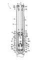
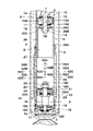
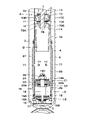
- FIG. 1 is a longitudinal sectional view showing a hydraulic shock absorber according to a first embodiment
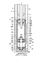
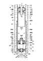
- FIG. FIG. 2 is a vertical cross-sectional view showing the hydraulic shock absorber in a state in which the piston in FIG. 1 is contracted to the maximum
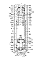
- 3 is an enlarged cross-sectional view showing a stopper mechanism and the like in FIG. 2
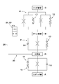
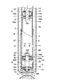
- FIG. FIG. 2 is an explanatory diagram showing an equivalent circuit of the hydraulic shock absorber according to the first embodiment
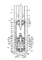
- FIG. It is sectional drawing which expands and shows a stopper mechanism etc. by 2nd Embodiment. It is sectional drawing which expands and shows a stopper mechanism etc. by 3rd Embodiment. It is sectional drawing which expands and shows a stopper mechanism etc. by a 1st modification.
- FIG. 11 is an enlarged cross-sectional view showing a stopper mechanism and the like according to a fourth embodiment; It is sectional drawing which expands and shows a stopper mechanism etc. by the 4th modification. It is sectional drawing which expands and shows the stopper mechanism etc. by a 5th modification.
- FIGS. 1 to 4 show the first embodiment.
- the hydraulic shock absorber 1 has an outer cylinder 2, an inner cylinder 6, a piston rod 7, a piston 9, a bottom valve 15, a stopper mechanism 20, and the like.
- the outer cylinder 2 of the hydraulic shock absorber 1 constitutes a second cylinder.
- the outer cylinder 2 forms an outer shell of the hydraulic shock absorber 1 and is formed in a tubular shape.
- a base end side (lower end in FIG. 1) as one end side of the outer cylinder 2 is a closed end closed by a bottom cap 3 .
- the tip side (upper end in FIG. 1) as the other end side of the outer cylinder 2 is an open end.
- a lid body 4 that closes the open end side of the outer cylinder 2 is attached to the open end (tip) side of the outer cylinder 2 in a removable state.
- a lid body 4 made of an annular disk is fixed to the outer cylinder 2 at its outer peripheral side while being in contact with the rod guide 8 in order to close the open end (tip) side of the outer cylinder 2 .
- a rod seal 5 made of an elastic material is provided on the inner peripheral side of the lid 4 .
- a rod seal 5 seals between the piston rod 7 and the lid 4 .
- the inner cylinder 6 constitutes a first cylinder.
- the inner cylinder 6 is provided inside the outer cylinder 2 while being coaxial with the outer cylinder 2 .
- One end (base end) side of the inner cylinder 6 is fitted and fixed to the bottom cap 3 side via a bottom valve 15 .
- a rod guide 8 is fitted and attached to the inner periphery of the inner cylinder 6 on the other end (tip) side of the open end.
- a working fluid containing an oil liquid is enclosed in the inner cylinder 6 .
- the working fluid is not limited to liquid oil (oil), and for example, water mixed with an additive can be used.
- An annular reservoir chamber A is formed between the inner cylinder 6 and the outer cylinder 2 .
- Gas is enclosed in the reservoir chamber A together with oil.
- This gas may be air at atmospheric pressure, or a gas such as compressed nitrogen gas may be used.
- the gas in the reservoir chamber A is compressed to compensate for the entry volume of the piston rod 7 when the piston rod 7 contracts (retraction stroke).
- the base end side of the piston rod 7 is inserted inside the inner cylinder 6 .
- the tip side of the piston rod 7 protrudes to the outside of the inner cylinder 6 via the rod guide 8, the lid 4 and the like so as to be able to expand and contract.
- the proximal end of the piston rod 7 is provided with a small-diameter rod portion 7A having a smaller radial dimension than other portions, and a male thread portion 7B formed at the end of the small-diameter rod portion 7A.
- a piston 9, an extension-side disk valve 12, and a compression-side disk valve 13 are attached to the small-diameter rod portion 7A.
- a nut 14 is screwed onto the male screw portion 7B.
- the rod guide 8 is fitted on the open end side of the outer cylinder 2 .
- the rod guide 8 is fixedly provided on the open end side of the inner cylinder 6 .
- the rod guide 8 includes a large-diameter portion 8A located on the upper side and inserted into the inner peripheral side of the outer cylinder 2, and a large-diameter portion 8A located below the large-diameter portion 8A. It is formed in a stepped cylindrical shape by the small diameter portion 8B inserted into the inner peripheral side of the cylinder 6. As shown in FIG.
- the large-diameter portion 8A of the rod guide 8 is provided with an annular oil reservoir 8C located radially inside the large-diameter portion 8A facing the lid 4 .
- the oil sump chamber 8C is an annular space surrounding the rod seal 5 and the piston rod 7 from the radial outside.
- the large-diameter portion 8A of the rod guide 8 is provided with a communication passage 8D that is always in communication with the reservoir chamber A on the outer cylinder 2 side.
- the communication passage 8D guides the oil (including gas) stored in the oil reservoir chamber 8C to the reservoir chamber A on the outer cylinder 2 side.
- the piston 9 constitutes the first piston.
- the piston 9 is provided on the small-diameter rod portion 7A of the piston rod 7 .
- the piston 9 is slidably fitted in the inner cylinder 6 .
- the piston 9 is composed of a piston body 10 and a seal member 11 .
- the piston 9 divides the inside of the inner cylinder 6 into two chambers, a lower bottom side chamber B (lower chamber) and an upper rod side chamber C (upper chamber).
- An intermediate valve 21 is provided between the bottom valve 15 and the piston 9 . Therefore, below the bottom side chamber B, an intermediate chamber D is formed between the bottom valve 15 and the intermediate valve 21 .
- the piston body 10 is provided on the outer peripheral side of the small-diameter rod portion 7A.
- the piston body 10 is made of, for example, sintered metal and has a substantially cylindrical shape.
- a rod mounting hole 10A through which the small-diameter rod portion 7A of the piston rod 7 is inserted is formed on the inner peripheral side of the piston body 10 .
- the piston body 10 is provided with a plurality of extension-side communicating passages 10B that are located radially outside the rod mounting hole 10A and that are drilled in the axial direction of the piston body 10 .
- the piston body 10 is provided with a plurality of compression side communication passages 10C drilled in the axial direction of the piston body 10 at positions different from the extension side communication passages 10B.
- Each elongation side communication passage 10B allows the bottom side chamber B and the rod side chamber C to communicate with each other.
- Each extension-side communication passage 10B generates an extension-side damping force due to the extension-side disk valve 12 when oil flows through each extension-side communication passage 10B.
- each contraction side communication passage 10C allows the bottom side chamber B and the rod side chamber C to communicate with each other.
- Each compression-side communication passage 10C generates a contraction-side damping force by the compression-side disk valve 13 when oil flows through each compression-side communication passage 10C.
- the sealing member 11 is fitted to the outer peripheral surface of the piston body 10 .
- the sealing member 11 is formed in a cylindrical shape using, for example, a fluororesin material.
- the sealing member 11 liquid-tightly seals between the rod-side chamber C and the bottom-side chamber B. As shown in FIG. In addition, the seal member 11 suppresses frictional resistance when the piston body 10 slides inside the inner cylinder 6 .
- the disk valve 12 on the extension side is arranged on one side end face (bottom side chamber B side) of the piston body 10 .
- the extension-side disc valve 12 is provided on the bottom side chamber B side of the piston body 10, for example, in a state in which a plurality of disc valves are stacked in the axial direction.
- the disc valve 12 When the piston rod 7 slides in the extension direction, the disc valve 12 generates a predetermined damping force by applying resistance to the oil flowing through the extension-side communication passage 10B.
- the disk valve 13 on the compression side is arranged on the other side end surface of the piston body 10 (rod side chamber C side).
- the compression-side disc valve 13 is provided on the rod-side chamber C side of the piston body 10, for example, in a state in which a plurality of disc valves are stacked in the axial direction.
- the disk valve 13 applies resistance to the oil flowing through the compression-side communication passage 10C to generate a predetermined damping force.
- the nut 14 is screwed onto the male threaded portion 7B of the piston rod 7.
- the nut 14 fixes the piston body 10 and the disk valves 12 and 13 to the small-diameter rod portion 7A of the piston rod 7 in a state of retaining them.
- the nut 14 detachably fixes the disk valve 12 on the extension side and the disk valve 13 on the compression side to both end faces of the piston 9 in the axial direction.
- the bottom valve 15 is positioned on the lower end side of the inner cylinder 6 and provided between the bottom cap 3 and the inner cylinder 6 .
- the bottom valve 15 includes a valve body 16 defining (partitioning) a reservoir chamber A and an intermediate chamber D between the bottom cap 3 and the inner cylinder 6, and a compression-side disk provided on the lower surface side of the valve body 16. It is composed of a valve 17 and an extension-side check valve 18 provided on the upper surface side of the valve body 16 .
- Communicating passages 16A and 16B are formed in the valve body 16 so as to allow the reservoir chamber A and the intermediate chamber D to communicate with each other in the circumferential direction.
- the compression-side disk valve 17 opens when the pressure in the intermediate chamber D exceeds the relief set pressure when the piston 9 slides downward in the compression stroke of the piston rod 7. It is relieved to the reservoir chamber A side through each communicating path 16A.
- the extension-side check valve 18 opens when the piston 9 slides upward during the extension stroke of the piston rod 7, and closes otherwise.
- the check valve 18 allows the oil in the reservoir chamber A to flow through the communication passages 16B toward the intermediate chamber D, and prevents the oil from flowing in the opposite direction.
- the stepped bolt 19 is a clearance forming member that forms an axial clearance between the intermediate valve 21 and the bottom valve 15 .
- the lower side of the stepped bolt 19 (bottom valve 15 side) is attached to the center of the valve body 16 (center portion in the radial direction).
- the stepped bolt 19 has a large diameter portion 19A located in the intermediate portion in the axial direction and having a large radial dimension, a small diameter portion 19B located in the upper portion in the axial direction and having a small radial dimension, and an end portion of the small diameter portion 19B. and a male threaded portion 19C to which the nut 25 is screwed.
- the stopper mechanism 20 operates during the contraction stroke of the piston rod 7 in which the piston 9 moves toward the bottom valve 15 inside the inner cylinder 6 .
- the stopper mechanism 20 has an intermediate valve 21, an intermediate chamber D, a shielding member 26, a through hole 30, a disc valve 23, and an intermediate cylinder 27.
- FIGS. 1 to 3 the stopper mechanism 20 has an intermediate valve 21, an intermediate chamber D, a shielding member 26, a through hole 30, a disc valve 23, and an intermediate cylinder 27.
- the intermediate valve 21 constitutes a second valve member. Intermediate valve 21 is provided between piston 9 and valve body 16 . As shown in FIG. 3, the intermediate valve 21 is positioned above the stepped bolt 19 (on the side of the piston 9) and attached to the small diameter portion 19B. The intermediate valve 21 is fixed to the stepped bolt 19 by a nut 25 so as to prevent it from coming off. An axial gap is formed between the bottom valve 15 and the intermediate valve 21 by the large-diameter portion 19A of the stepped bolt 19 . This gap forms an annular space positioned between the large-diameter portion 19A and the inner cylinder 6 to surround the large-diameter portion 19A. This space serves as an intermediate chamber D formed between the bottom valve 15 and the intermediate valve 21 .
- the intermediate valve 21 includes a valve body 22 defining (partitioning) a bottom side chamber B and an intermediate chamber D between the piston 9 and the bottom valve 15, and a compression side disk valve provided on the lower surface side of the valve body 22. 23 and a check valve 24 on the expansion side provided on the upper surface side of the valve body 22 .
- Communicating passages 22A and 22B are formed in the valve body 22 so that the bottom side chamber B and the intermediate chamber D can be communicated with each other in the circumferential direction.
- the compression side disc valve 23 opens when the pressure in the bottom side chamber B exceeds a predetermined set pressure when the piston 9 slides downward in the compression stroke of the piston rod 7, and the pressure at this time is , to the intermediate chamber D side via the communication passages 22A. At this time, the set pressure at which the disc valve 23 opens is set to a pressure higher than the relief set pressure of the bottom valve 15 .
- the compression-side disk valve 23 is provided in the intermediate valve 21 and constitutes a second valve that generates a damping force during the compression stroke.
- the extension-side check valve 24 opens when the piston 9 slides upward during the extension stroke of the piston rod 7, and closes otherwise.
- the check valve 24 allows the oil in the intermediate chamber D to flow through the communication passages 22B toward the bottom side chamber B, and prevents the oil from flowing in the opposite direction.
- the shielding member 26 is attached to the lower side of the piston 9 (on the side of the intermediate valve 21).
- the shielding member 26 includes a cylindrical portion 26A and a bottom portion 26B which is the upper end portion of the cylindrical portion 26A and has a plurality of communication passages 26C.
- the shielding member 26 is formed in a cup shape with an open bottom end.
- the outer diameter dimension of the cylindrical portion 26A is formed smaller than the inner diameter dimension of the inner cylinder 6 .
- the bottom portion 26B is attached to the small-diameter rod portion 7A of the piston rod 7 while being sandwiched between the piston 9 and the nut 14. As shown in FIG.
- the shielding member 26 moves with respect to the inner cylinder 6 together with the piston 9 .
- the intermediate tube 27 is a separate tube separate from the outer tube 2 and the inner tube 6, and is arranged between the outer tube 2 and the inner tube 6.
- the intermediate cylinder 27 is formed of, for example, a cylindrical cylinder.
- the intermediate cylinder 27 is positioned below the inner cylinder 6 (bottom valve 15 side) and attached to the outer peripheral side of the inner cylinder 6 .
- the intermediate cylinder 27 surrounds the entire outer circumference of the inner cylinder 6 and extends in the axial direction. Both ends of the intermediate cylinder 27 in the axial direction are fixed to the outer peripheral surface of the inner cylinder 6 .
- the axial dimension of the intermediate tube 27 is longer than the axial dimension of the shielding member 26, for example.
- a cylindrical space is formed between the intermediate cylinder 27 and the inner cylinder 6 .
- This space serves as a bypass channel 28 formed between the intermediate cylinder 27 and the inner cylinder 6 .
- the bypass flow path 28 allows the bottom side chamber B and the intermediate chamber D to communicate with each other.
- the inner cylinder 6 is formed with a through hole 29 located inside the intermediate cylinder 27 and opening to the intermediate chamber D on one side.
- the through hole 29 is arranged axially between the bottom valve 15 and the intermediate valve 21 .
- the inner cylinder 6 is formed with a through hole 30 on the other side that is positioned inside the intermediate cylinder 27 and opens to the bottom side chamber B.
- Both through holes 29 and 30 are formed in a circular shape.
- the through holes 29 and 30 may be formed in other shapes such as square, polygonal, elliptical, and the like.
- a through hole 30 is formed in the inner cylinder 6 in a portion surrounded by the intermediate cylinder 27 and located above the intermediate valve 21 on the other side (bottom side chamber B side).
- the through hole 30 constitutes a second adjusting member.
- the opening area of the through hole 30 is smaller than the opening area of the through hole 29, for example.
- a plurality of (for example, three) through holes 30 are formed in the inner cylinder 6 .
- the plurality of through holes 30 are arranged at different positions in the axial direction.
- the bypass channel 28 connecting the bottom side chamber B and the intermediate chamber D is opened or closed according to the relative positions of the through holes 30 and the shielding member 26 . That is, the through hole 30 and the shielding member 26 function as a two-port two-position directional control valve that communicates or blocks the bypass flow path 28 (see FIG. 4).
- the shielding member 26 is positioned above all the through holes 30 .
- the through-hole 30 allows the bottom-side chamber B and the bypass channel 28 to communicate with each other. Therefore, in the first stroke range in which the through hole 30 is opened, when the pressure in the bottom side chamber B rises during the compression stroke of the piston 9, the oil in the bottom side chamber B is mainly supplied to the intermediate chamber D through the bypass passage 28. be done.
- the hydraulic shock absorber 1 has the configuration as described above, and the operation thereof will be described next.
- the hydraulic shock absorber 1 has the tip side of the piston rod 7 attached to the vehicle body side of the automobile, and the base end side of the outer cylinder 2 attached to the axle (neither shown) side.
- the shielding member 26 is positioned above all the through holes 30 .
- the through-hole 30 allows the bottom-side chamber B and the bypass channel 28 to communicate with each other.
- the first stroke range in which the through hole 30 is thus opened, when the pressure in the bottom side chamber B rises during the compression stroke of the piston 9, the oil in the bottom side chamber B is mainly supplied to the intermediate chamber D through the bypass passage 28. be done. Therefore, in the first stroke range, the pressure in the intermediate chamber D rises according to the pressure in the bottom side chamber B, and the oil in the intermediate chamber D flows through the communicating passage 16A of the bottom valve 15 and the disc valve 17 into the reservoir chamber. circulates into A, and the first damping force on the contraction side is generated.
- the hydraulic shock absorber 1 includes an inner cylinder 6 (first cylinder) in which a working fluid is sealed, and is slidably fitted in the inner cylinder 6. into a rod-side chamber C and a bottom-side chamber B, a piston rod 7 connected to the piston 9, and a disk valve 17 ( A bottom valve 15 (first valve member) having a first valve), an outer cylinder 2 (second cylinder) provided on the outer peripheral side of the inner cylinder 6, and formed between the inner cylinder 6 and the outer cylinder 2 It has a reservoir chamber A and a stopper mechanism 20 that operates during the compression stroke of the piston rod 7 in which the piston 9 moves toward the bottom valve 15 inside the inner cylinder 6 .
- the stopper mechanism 20 includes an intermediate valve 21 (second valve member) provided between the piston 9 and the bottom valve 15, an intermediate chamber D formed between the bottom valve 15 and the intermediate valve 21, and the piston 9.
- Shielding member 26 first adjusting member
- Shielding member 26 that moves with respect to inner cylinder 6, and bottom-side chamber B side in which bypass flow path 28 connecting bottom-side chamber B and intermediate chamber D is opened and closed depending on the relative position of shielding member 26.
- a disc valve 23 (second valve) provided in the intermediate valve 21 to generate a damping force during the compression stroke.
- the hydraulic shock absorber 1 generates the first damping force by the bottom valve 15 (disk valve 17) while the piston 9 is in the first stroke range.
- the hydraulic shock absorber 1 generates a second damping force higher than the first damping force by the disc valve 23 during a second stroke range in which the piston 9 exceeds the first stroke range and is positioned on the intermediate valve 21 side.
- the intermediate valve 21 is provided between the piston 9 and the bottom valve 15 in contrast to the normal twin-cylinder damper having the inner cylinder 6 and the outer cylinder 2, so that the piston 9 is damped.
- the lower space is divided into a bottom side chamber B and an intermediate chamber D.
- an intermediate cylinder 27 is arranged outside the inner cylinder 6, and by providing through holes 29 and 30 in the inner cylinder 6, a bypass flow path 28 bypassing between the bottom side chamber B and the intermediate chamber D is formed. forming.
- a cup-shaped shielding member 26 is disposed below the piston 9, and the shielding member 26 sequentially closes the plurality of through holes 30 during the contraction stroke (compression stroke) of the damper.
- the flow path of the oil flowing between the bottom side chamber B and the intermediate chamber D is shifted from the bypass flow path 28 to the damping force generating mechanism provided in the intermediate valve 21 .
- the hydraulic shock absorber 1 generates a higher damping force (second damping force) while the piston 9 is in the second stroke range than while the piston 9 is in the first stroke range.
- the intermediate valve 21 is provided between the piston 9 and the bottom valve 15 in the first embodiment.
- the damping force can be changed by opening and closing the through hole 30 which is divided into the bottom side chamber B and the intermediate chamber D and which bypasses the bottom side chamber B and the intermediate chamber D.
- the degree of freedom in setting the damping force is increased, and the cost can be kept low.
- the bottom valve 15 and the intermediate valve 21 are connected in series.
- the hydraulic shock absorber 1 includes a bypass flow path 28 that bypasses the intermediate valve 21 , and a shielding member 26 and a through hole 30 that open and close the bypass flow path 28 .
- the bypass channel 28 is opened or closed.
- a first damping force can be generated by the bottom valve 15 when the bypass flow path 28 is in communication.
- a second damping force can be generated by the intermediate valve 21 when the bypass flow path 28 is blocked.
- the bottom valve 15 and the intermediate valve 21 are connected in series, the structure can be simplified compared to the case where they are connected in parallel.
- the second adjustment member is configured by a through hole 30 formed in the inner cylinder 6.
- a plurality of through holes 30 are provided in a staggered manner in the axial direction.
- the connection of the damping force can be smoothed.
- the change in damping force can be adjusted according to the arrangement, number, and size of the through-holes 30 . Therefore, compared with the case where the through hole 30 is single, the degree of freedom in adjusting the damping force can be increased.
- the piston rod 7 retracts, abrupt or smooth changes in damping force are possible depending on the specification. Since a plurality of through-holes 30 are displaced in the axial direction, this is effective when the stroke range of the piston 9 has a margin.
- the case where three through-holes 30 are provided in the inner cylinder 6 is exemplified.
- the present invention is not limited to this, and one or two through-holes 30 may be provided in the inner cylinder 6, or four or more through-holes 30 may be provided.
- FIG. 5 shows a second embodiment of the present invention.
- the stopper mechanism includes an axially displaceable sub-piston and a shielding member provided on the sub-piston for opening and closing the bypass flow path.
- the same reference numerals are assigned to the same configurations as in the first embodiment described above, and the description thereof will be omitted.
- a bolt 31 is attached to the bottom valve 15 in the second embodiment.
- the bolt 31 is attached to the center (central portion in the radial direction) of the valve body 16 .
- a bolt 31 secures the disc valve 17 and the check valve 18 to the valve body 16 .
- a bottomed cylindrical holder 32 for holding the spring 50 is attached to the upper end of the bolt 31 .
- the stopper mechanism 41 operates during the contraction stroke of the piston rod 7 in which the piston 9 moves toward the bottom valve 15 inside the inner cylinder 6 .
- the stopper mechanism 41 has a sub-piston 42 , an intermediate chamber D, a shielding member 51 , a through hole 54 , a disk valve 46 and an intermediate cylinder 52 .
- the sub-piston 42 constitutes a second valve member.
- a sub-piston 42 is provided between the piston 9 and the valve body 16 .
- the sub-piston 42 is accommodated in a sub-cylinder 43 that extends from the lower end of the inner cylinder 6 .
- the sub-cylinder 43 has a body portion 43A having substantially the same outer diameter as the inner cylinder 6, and a small-diameter connecting portion 43B positioned on the upper end side and inserted into the inner cylinder 6. As shown in FIG.
- the sub-cylinder 43 constitutes a first cylinder together with the inner cylinder 6 .
- the sub-piston 42 is slidably fitted in the sub-cylinder 43 .
- the sub-piston 42 is composed of a piston body 44 and a seal member 45 .
- a spring 50 such as a coil spring is provided in the sub-cylinder 43 between the sub-piston 42 and the bottom valve 15 .
- a lower end portion of the spring 50 is connected to the holder 32 while being fitted to the outer peripheral surface of the holder 32 .
- the upper end portion of the spring 50 is inserted into the cylindrical portion 51A of the shielding member 51 and is in contact with the bottom portion 51B of the shielding member 51 .
- a spring 50 biases the sub-piston 42 toward the piston 9 .
- the sub-piston 42 is held in the sub-cylinder 43 with its upward displacement in the axial direction restricted by the connecting portion 43B of the sub-cylinder 43 .
- the spring 50 is a gap forming member that forms an axial gap between the sub-piston 42 and the bottom valve 15 .
- a spring 50 forms an axial space between the bottom valve 15 and the sub-piston 42 .
- This space serves as an intermediate chamber D formed between the bottom valve 15 and the sub-piston 42 .
- the piston body 44 is made of, for example, sintered metal and has a substantially cylindrical shape.
- a bolt mounting hole 44A through which a bolt 48 is inserted is formed on the inner peripheral side of the piston body 44 .
- the piston body 44 is provided with a plurality of compression side communication passages 44B which are located radially outside the bolt mounting holes 44A and which are drilled in the axial direction of the piston body 44 .
- the piston body 44 is provided with a plurality of extension side communication passages 44C which are located at different positions from the compression side communication passages 44B and which are drilled in the axial direction of the piston body 44 .
- Each contraction side communication passage 44B allows the bottom side chamber B and the intermediate chamber D to communicate with each other.
- Each compression-side communication passage 44B generates a contraction-side damping force by the compression-side disk valve 46 when oil flows through each compression-side communication passage 44B.
- each extension side communication passage 44C allows the bottom side chamber B and the intermediate chamber D to communicate with each other.
- Each extension-side communication passage 44C generates an extension-side damping force by the extension-side disk valve 47 when oil flows through each extension-side communication passage 44C.
- the seal member 45 is fitted to the outer peripheral surface of the piston body 44 .
- the seal member 45 is formed in a cylindrical shape using, for example, a fluororesin material.
- the sealing member 45 liquid-tightly seals between the bottom side chamber B and the intermediate chamber D. As shown in FIG. Further, the seal member 45 suppresses frictional resistance when the piston body 44 slides inside the sub-cylinder 43 .
- the disk valve 46 on the compression side is arranged on the upper surface side of the piston body 44 .
- the compression side disk valve 46 is provided, for example, on the bottom side chamber B side of the piston body 44 .
- the disc valve 46 applies resistance to the oil flowing through the compression side communication passage 44B to generate a predetermined damping force.
- the disk valve 46 is provided on the sub-piston 42 and constitutes a second valve that generates a damping force during the compression stroke.
- the disk valve 47 on the extension side is arranged on the lower surface side of the piston body 44 .
- the extension-side disc valve 47 is provided on the intermediate chamber D side of the piston body 44, for example, in a state in which a plurality of disc valves are stacked in the axial direction.
- the disk valve 47 applies resistance to the oil flowing through the extension-side communication passage 44C to generate a predetermined damping force.
- the bolt 48 is inserted into the bolt mounting hole 44A of the piston body 44.
- a male threaded portion 48 ⁇ /b>A to which a nut 49 is screwed is formed at the tip (upper end) of the bolt 48 .
- a brim portion 48B having a large outer diameter is formed at the base end (lower end) of the bolt 48 .
- a nut 49 connects the piston body 44 and the disc valves 46 and 47 .
- the tip surface of the bolt 48 can come into contact with the tip surface of the piston rod 7 (the male threaded portion 7B). When the piston rod 7 moves in the contraction direction, the tip surface of the piston rod 7 comes into contact with the tip surface of the bolt 48 . This causes the sub-piston 42 to move toward the bottom valve 15 together with the bolt 48 .
- the shielding member 51 is attached to the lower side of the sub-piston 42 (bottom valve 15 side).
- the shielding member 51 has a cylindrical portion 51A and a bottom portion 51B at the upper end portion of the cylindrical portion 51A.
- the bottom portion 51B has a plurality of communication paths 51C.
- the shielding member 51 is formed in a cup shape with an open bottom end.
- the outer diameter dimension of the cylindrical portion 51A is formed smaller than the inner diameter dimension of the sub-cylinder 43 .
- the bottom portion 51B is attached to the sub-piston 42 while being sandwiched between the flange portion 48B of the bolt 48 and the piston body 44 .
- the shielding member 51 moves with respect to the sub-cylinder 43 together with the sub-piston 42 .
- the intermediate cylinder 52 is a separate tube separate from the outer cylinder 2, the inner cylinder 6, and the sub-cylinder 43, and is arranged between the outer cylinder 2 and the inner cylinder 6.
- the intermediate cylinder 52 is formed of, for example, a cylindrical cylinder.
- the intermediate cylinder 52 is arranged below the inner cylinder 6 (on the side of the bottom valve 15 ) and surrounds the sub-cylinder 43 , and is attached to the outer peripheral side of the inner cylinder 6 and the sub-cylinder 43 .
- the intermediate cylinder 52 surrounds the outer circumferences of the inner cylinder 6 and the sub-cylinder 43 over the entire circumference, and extends axially from the axial middle portion of the inner cylinder 6 to the lower end of the sub-cylinder 43 .
- the axial upper end portion of the intermediate cylinder 52 is fixed to the outer peripheral surface of the inner cylinder 6 .
- the axial lower end portion of the intermediate cylinder 52 is fixed to the outer peripheral surface of the sub-cylinder 43 .
- a cylindrical space is formed between the intermediate cylinder 52, the inner cylinder 6, and the sub-cylinder 43.
- This space serves as a bypass passage 53 formed between the intermediate cylinder 52 , the inner cylinder 6 and the sub-cylinder 43 .
- the bypass channel 53 allows the bottom side chamber B and the intermediate chamber D to communicate with each other.
- the sub-cylinder 43 is axially positioned between the bottom valve 15 and the sub-piston 42 and formed with a through hole 54 on one side (intermediate chamber D side).
- the through hole 54 constitutes a second adjusting member.
- the through hole 54 is located inside the intermediate cylinder 52 and opens to the intermediate chamber D. As shown in FIG.
- the inner cylinder 6 is formed with a through hole 55 on the other side that is located inside the intermediate cylinder 52 and opens to the bottom side chamber B. As shown in FIG. Both of the through holes 54 and 55 are formed in a circular shape. The through holes 54 and 55 may be formed in other shapes such as square, polygonal, elliptical, and the like.
- a bypass flow path 53 connecting the bottom side chamber B and the intermediate chamber D is opened or closed according to the relative positions of the through hole 54 and the shielding member 51 . That is, the through hole 54 and the shielding member 51 function as a 2-port 2-position directional control valve that communicates or blocks the bypass flow path 53 .
- the shielding member 51 is positioned above the through hole 54 .
- the through hole 54 allows the intermediate chamber D and the bypass channel 53 to communicate with each other. Therefore, in the first stroke range in which the through hole 54 is opened, when the pressure in the bottom side chamber B rises during the compression stroke of the piston 9, the oil in the bottom side chamber B is mainly supplied to the intermediate chamber D through the bypass passage 53. be done. Therefore, in the first stroke range, when the pressure in the intermediate chamber D rises according to the pressure in the bottom side chamber B, the oil in the intermediate chamber D flows through the communication passage 16A of the bottom valve 15 and the disc valve 17 into the reservoir chamber. circulates into A, and the first damping force on the contraction side is generated.
- the piston rod 7 contacts the bolt 48, and the shielding member 51 is displaced downward together with the sub-piston 42. Thereby, the shielding member 51 partially or entirely blocks the through hole 54 .
- the volume of the bottom side chamber B is kept substantially constant.
- the bypass channel 53 is cut off from the intermediate chamber D. Therefore, in the second stroke range in which the through-hole 54 is at least partially closed, the pressure in the intermediate chamber D increases as the sub-piston 42 approaches the bottom valve 15 . As a result, part of the hydraulic fluid in the intermediate chamber D whose pressure has increased is supplied to the bottom side chamber B via the sub-piston 42 .
- the oil in the intermediate chamber D flows through the compression side communication passage 44B of the sub-piston 42 and the disc valve 46. and flows into the bottom side chamber B to generate a second contraction-side damping force.
- the set pressure at which the disc valve 46 opens is set to a pressure higher than the relief set pressure of the bottom valve 15 . Therefore, the second damping force of the sub-piston 42 becomes higher (larger) than the first damping force of the bottom valve 15 .
- the sub-piston 42 can generate a high second damping force before the piston 9 reaches the most retracted state where it comes closest to the bottom valve 15 .
- a sub-piston 42 that can be displaced in the axial direction is provided between the piston 9 and the bottom valve 15, and the sub-piston 42 is provided with a shielding member 51 that opens and closes the bypass flow path 53. . Therefore, when the piston 9 approaches the bottom valve 15 during the contraction stroke of the piston rod 7, the sub-piston 42 and the shielding member 51 are displaced toward the bottom valve 15 by the piston rod 7, and the bypass passage 53 and the intermediate chamber D are displaced. cut off between Thereby, when the piston 9 comes closest to the bottom valve 15, the damping force can be increased.
- FIG. 6 shows a third embodiment of the present invention.
- a feature of the third embodiment is that a plurality of through holes communicating with the bypass flow path are provided in the axial direction, and the opening area of the through hole near the bottom valve is made smaller than the opening area of the through hole away from the bottom valve. I have done it.
- the same reference numerals are assigned to the same configurations as in the first embodiment described above, and the description thereof will be omitted.
- the stopper mechanism 61 operates during the contraction stroke of the piston rod 7 in which the piston 9 moves toward the bottom valve 15 inside the inner cylinder 6 .
- the stopper mechanism 61 is configured similarly to the stopper mechanism 20 according to the first embodiment.
- the stopper mechanism 61 has an intermediate valve 21 , an intermediate chamber D, a shielding member 26 , through holes 62 A to 62 E, a disk valve 23 and an intermediate cylinder 27 .
- the inner cylinder 6 is formed with a through hole 29 located inside the intermediate cylinder 27 and opening to the intermediate chamber D.
- the through hole 29 is arranged between the bottom valve 15 and the intermediate valve 21 .
- the inner cylinder 6 is formed with through-holes 62A to 62E on the other side that are located in the intermediate cylinder 27 and open to the bottom side chamber B. As shown in FIG.
- the through holes 62A-62E constitute a second adjustment member.
- the through holes 62A to 62E are portions surrounded by the intermediate tube 27 and arranged above the intermediate valve 21 of the inner tube 6. As shown in FIG.
- the through holes 62A to 62E are arranged at different positions in the axial direction.
- the through holes 62A to 62E are arranged in a row in the axial direction.
- the through hole 62A is arranged on the uppermost side (on the side of the piston 9).
- the through hole 62B is arranged below the through hole 62A (bottom valve 15 side).
- 62 C of through-holes are arrange
- the through hole 62D is arranged below the through hole 62C.
- the through hole 62E is arranged below the through hole 62D. Therefore, the through hole 62E is arranged on the lowest side.
- the opening areas of the through holes 62A to 62E become smaller as they approach the bottom valve 15. Therefore, the opening area of the through hole 62B is smaller than the opening area of the through hole 62A.
- the opening area of the through hole 62C is smaller than the opening area of the through hole 62B.
- the opening area of through-hole 62D is smaller than the opening area of through-hole 62C.
- the opening area of the through hole 62E is smaller than the opening area of the through hole 62D.
- the opening area of the through hole 62A is the largest.
- the opening area of the through hole 62E is the smallest.
- a plurality of (for example, four) through-holes 62A to 62E are provided at different positions in the inner cylinder 6 in the circumferential direction.
- 62 A of several through-holes are arrange
- the plurality of through holes 62B to 62E are arranged, for example, at equal intervals in the circumferential direction.
- the bypass channel 28 connecting the bottom side chamber B and the intermediate chamber D is opened or closed according to the relative positions of the through holes 62A to 62E and the shielding member 26.
- a plurality of through holes 62A to 62E are provided at different positions in the axial direction, and the opening areas of these through holes 62A to 62E are made smaller as they approach the bottom valve 15.
- FIG. Therefore, when the piston 9 approaches the bottom valve 15 during the contraction stroke of the piston 9, the through holes 62A to 62E are sequentially closed by the blocking member 26.
- FIG. At this time, since at least a portion of the through holes 62A to 62E are closed to enter the second stroke range, the amount of oil flowing from the bottom side chamber B into the bypass passage 28 as the piston 9 approaches the bottom valve 15. The flow area can be gradually decreased. As a result, when switching from the first damping force by the bottom valve 15 to the second damping force by the intermediate valve 21, the damping force can be changed smoothly.
- the third embodiment has been described by taking as an example the case where it is applied to the first embodiment.
- the present invention is not limited to this, and the third embodiment may be applied to the second embodiment.
- the stopper mechanism 61 according to the third embodiment is configured to have through holes 62A to 62E arranged in a row in the axial direction.
- the present invention is not limited to this, and like a stopper mechanism 63 according to a first modified example shown in FIG. .
- the plurality of through holes 64 may have the same opening area or different opening areas. Also, only one through-hole 64 may be provided at the same position in the axial direction, or a plurality of through-holes 64 may be provided at the same position in the axial direction but at different positions in the circumferential direction.
- the stopper mechanism 61 according to the third embodiment is configured to have circular through holes 62A to 62E.
- the present invention is not limited to this, and like a stopper mechanism 65 according to a second modified example shown in FIG. good. In this case, only one through-hole 66 may be provided, or a plurality of through-holes 66 may be provided at different positions in the circumferential direction.
- the stopper mechanism 61 according to the third embodiment has through holes 62A to 62E arranged in a line in the axial direction.
- the present invention is not limited to this.
- a stopper mechanism 67 according to a third modification shown in FIG. They may be arranged at different positions in the circumferential direction.
- FIG. 10 shows a fourth embodiment of the present invention.
- the first adjusting member is formed of a bellows-like tubular body that can be expanded and contracted in the axial direction, and a through hole is formed in the tubular body.
- symbol is attached
- the stopper mechanism 71 operates during the compression stroke of the piston rod 7 in which the piston 9 moves toward the bottom valve 15 inside the inner cylinder 6 .
- the stopper mechanism 71 is configured similarly to the stopper mechanism 20 according to the first embodiment.
- the stopper mechanism 71 has an intermediate valve 21 , an intermediate chamber D, a shielding member 72 , a through hole 73 , a disk valve 23 and an intermediate cylinder 27 .
- the bypass channel 28 allows the bottom side chamber B and the intermediate chamber D to communicate with each other.
- the inner cylinder 6 is formed with a through hole 29 located inside the intermediate cylinder 27 and opening to the intermediate chamber D on one side.
- the inner cylinder 6 is formed with a through hole 74 on the other side that is located inside the intermediate cylinder 27 and opens to the bottom side chamber B.
- the through hole 74 is arranged above the intermediate valve 21 .
- a plurality of (for example, two) through holes 74 are formed in the inner cylinder 6 .
- the plurality of through holes 74 are arranged at different positions in the circumferential direction.
- the through hole 74 is formed in a circular shape.
- the through holes 74 may be formed in other shapes such as squares, polygons, ellipses, and the like.
- the shielding member 72 is attached to the lower side of the piston 9 (the intermediate valve 21 side).
- the shielding member 72 constitutes a first adjusting member and is formed of a bellows-like cylindrical body that can be expanded and contracted in the axial direction.
- the shielding member 72 is formed with a plurality of through holes 73 as second adjusting members.
- the through hole 73 is arranged in the constricted portion 72A of the shielding member 72 .
- the lower end of the shielding member 72 forms a circular opening that can come into contact with the intermediate valve 21 .
- the upper end portion of the shielding member 72 is a bottom portion 72B having a plurality of communication paths 72C.
- the lower end of the shielding member 72 comes into contact with the intermediate valve 21, and the shielding member 72 shrinks in the axial direction. At this time, a part of the bottom side chamber B is formed inside the shielding member 72 . Further, as the shielding member 72 is reduced, the opening area of the through hole 73 is also reduced. As a result, since the piston 9 is positioned in the second stroke range, part of the oil inside the shielding member 72 (inside the bottom side chamber B) is supplied to the intermediate chamber D via the intermediate valve 21 . When the shielding member 72 shrinks and the through hole 73 is completely closed, the pressure in the bottom side chamber B rises in the contraction stroke of the piston 9, and the oil in the bottom side chamber B flows mainly through the intermediate valve 21. It is supplied to the intermediate chamber D.
- the fourth embodiment has been described by taking as an example the case where it is applied to the first embodiment.
- the present invention is not limited to this, and the fourth embodiment may be applied to the second embodiment.
- the stopper mechanism 71 according to the fourth embodiment includes a shielding member 72 formed of a bellows-shaped tubular body as a first adjustment member, and a through hole 73 as a second adjustment member formed in the shielding member 72. It was configured.
- the present invention is not limited to this, but like a stopper mechanism 75 according to a fourth modification shown in FIG. It is good also as a structure provided with the through-hole 77 of this.
- the lower end of the shielding member 76 has an opening surface inclined from a plane perpendicular to the axial direction.
- the upper end portion of the shielding member 76 is a bottom portion 76A having a plurality of communication passages 76B.
- the plurality of through holes 77 are arranged at the same position in the axial direction and at different positions in the circumferential direction. Thereby, the shielding member 76 can sequentially close the plurality of through holes 77 as the piston 9 approaches the bottom valve 15 .
- the fourth modified example can be applied even when the stroke range of the piston 9 has little margin compared to the third embodiment, for example.
- the plurality of through holes 77 arranged at different positions in the circumferential direction may have different opening areas.
- a shielding member 79 as a first adjustment member and a plurality of through holes 77 as a second adjustment member formed in the inner cylinder 6 are It is good also as a structure provided.
- the outer diameter dimension of the shielding member 79 decreases from the upper end to the lower end.
- the upper end portion of the shielding member 79 is a bottom portion 79A having a plurality of communication paths 79B.
- the hydraulic shock absorber 1 for a vehicle has been described as a representative example of the shock absorber.
- the present invention is not limited to this, and may be used, for example, in hydraulic shock absorbers used in various machines other than vehicles, buildings, and the like.
- shock absorbers based on the embodiments described above, for example, the following modes are conceivable.
- a second cylinder provided; a reservoir chamber formed between the first cylinder and the second cylinder; and the first piston moving toward the first valve member in the first cylinder.
- a stopper mechanism that operates during a compression stroke of the piston rod, the stopper mechanism comprising a second valve member provided between the first piston and the first valve member; and the first valve member. and the second valve member, a first adjustment member that moves with the first piston with respect to the first cylinder, and the first adjustment member. a second adjustment member that opens and closes a bypass passage connecting the intermediate chamber; and a second valve that is provided in the second valve member and generates a damping force during a contraction stroke.
- the first valve generates a first damping force
- the second stroke range in which the first piston exceeds the first stroke range and is positioned on the second valve member side.
- the second valve generates a second damping force higher than the first damping force.
- the first valve and the second valve are connected in series.
- the second adjusting member is a through hole formed in the first cylinder, and a plurality of the through holes are provided with being shifted in the axial direction.
- the second adjustment member is a through hole formed in the first cylinder, and a plurality of through holes are provided in the circumferential direction.
- Hydraulic shock absorber (buffer) 2 outer cylinder (second cylinder) 6 inner cylinder (first cylinder) 7 piston rod 9 piston (first piston) 15 bottom valve (first valve member) 17 disk valve (first valve) 18, 24 check valve 20, 41, 61, 63, 65, 67, 71, 75, 78 stopper mechanism 21 intermediate valve (second valve member) 23, 46 disk valve (second valve) 26, 51, 72, 76, 79 shielding member (first adjusting member) 27, 52 intermediate tube 28, 53 bypass flow path 30, 54, 62A to 62E, 64, 66, 68A to 68C, 73, 77 through hole (second adjustment member) 42 sub-piston (second valve member) 43 sub-cylinder (first valve member)
Landscapes
- Engineering & Computer Science (AREA)
- General Engineering & Computer Science (AREA)
- Mechanical Engineering (AREA)
- Fluid-Damping Devices (AREA)
Abstract
ストッパ機構(20)は、ピストン(9)とボトムバルブ(15)との間に設けられる中間バルブ(21)と、ボトムバルブ(15)と中間バルブ(21)の間に形成される中間室(D)と、ピストン(9)と共に内筒(6)に対し移動する遮蔽部材(26)と、遮蔽部材(26)との相対位置により、ボトム側室(B)と中間室(D)とを繋ぐバイパス流路(28)が開閉される貫通孔(30)と、中間バルブ(21)に設けられ縮み行程時に減衰力を発生するディスクバルブ(23)と、を有している。
Description
本開示は、例えば4輪自動車等の車両に搭載され、車両の振動を緩衝するのに好適に用いられる緩衝器に関する。
一般に、4輪自動車等の車両には、各車輪(車軸側)と車体との間に油圧緩衝器が設けられ、車両の振動を緩衝するようにしている(例えば、特許文献1参照)。特許文献1に記載には、油圧緩衝器のピストン側油室とロッド側油室との間に設けられた減衰力発生装置が開示されている。この減衰力発生装置には、ピストン側油室とロッド側油室との間を連通する通孔が設けられている。ピストンロッドの先端部には、減衰力発生装置の通孔に進退可能なニードルが設けられている。
特許文献1に記載された油圧緩衝器は、ピストンがシリンダのボトム側に向けて移動する圧側行程(縮み行程)において、通孔にニードルが挿入された後は、減衰力発生装置によって減衰力を発生させる。しかしながら、通孔からニードルが離れた位置にある間は、通孔を通じてピストン側油室とロッド側油室との間で油が流通するから、減衰力発生装置による減衰力は発生しない。このため、圧側行程のうちピストンがシリンダのボトムから離れた位置を移動する通常ストローク範囲で、所望の減衰力が得られないという問題がある。
本発明の一実施形態の目的は、縮み行程において、通常ストローク範囲で減衰力を発生させるのに加え、通常ストローク範囲を超えてピストンがシリンダのボトム側に近付くときに、さらに高い減衰力を発生させることができる緩衝器を提供することにある。
本発明の一実施形態による緩衝器は、作動流体が封入された第1シリンダと、前記第1シリンダ内に摺動可能に嵌装され、該第1シリンダ内をロッド側室とボトム側室に区画する第1ピストンと、前記第1ピストンに連結されるピストンロッドと、前記ボトム側室に設けられ、縮み行程時に減衰力を発生させる第1バルブを有する第1バルブ部材と、前記第1シリンダの外周側に設けられる第2シリンダと、前記第1シリンダと前記第2シリンダとの間に形成されるリザーバ室と、前記第1ピストンが前記第1シリンダ内の前記第1バルブ部材側に向けて移動する前記ピストンロッドの縮み行程のときに作動するストッパ機構と、を有し、前記ストッパ機構は、前記第1ピストンと前記第1バルブ部材との間に設けられる第2バルブ部材と、前記第1バルブ部材と前記第2バルブ部材の間に形成される中間室と、前記第1ピストンと共に前記第1シリンダに対し移動する第1調整部材と、前記第1調整部材との相対位置により、前記ボトム側室と前記中間室とを繋ぐバイパス流路が開閉される第2調整部材と、前記第2バルブ部材に設けられ縮み行程時に減衰力を発生する第2バルブと、を有し、前記第1ピストンが第1ストローク範囲にある間は、前記第1バルブにより第1減衰力を発生させ、前記第1ピストンが前記第1ストローク範囲を超えて前記第2バルブ部材側に位置する第2ストローク範囲の間は、前記第2バルブにより前記第1減衰力よりも高い第2減衰力を発生させる。
本発明の一実施形態によれば、縮み行程において、第1ストローク範囲で第1減衰力を発生させるのに加え、第1ストローク範囲を超えてピストンがシリンダのボトム側に近付くときに、第1減衰力よりも高い第2減衰力を発生させることができる。
以下、本発明の実施形態に係る緩衝器を、車両用の油圧緩衝器に適用した場合を例に挙げて、添付図面に従って詳細に説明する。
ここで、図1ないし図4は第1の実施形態を示している。図1において、油圧緩衝器1は、外筒2、内筒6、ピストンロッド7、ピストン9、ボトムバルブ15、ストッパ機構20等を有している。
油圧緩衝器1の外筒2は、第2シリンダを構成している。外筒2は、油圧緩衝器1の外殻をなし、筒状に形成されている。外筒2の一端側としての基端側(図1中の下端)は、ボトムキャップ3によって閉塞された閉塞端となっている。外筒2の他端側としての先端側(図1中の上端)は、開口端となっている。外筒2の開口端(先端)側には、外筒2の開口端側を閉塞する蓋体4が抜止め状態で取り付けられている。
環状円板からなる蓋体4は、外筒2の開口端(先端)側を閉塞するためロッドガイド8に当接した状態で、その外周側が外筒2に固定されている。蓋体4の内周側には、弾性材料からなるロッドシール5が設けられている。ロッドシール5は、ピストンロッド7と蓋体4との間をシールしている。
内筒6は、第1シリンダを構成している。内筒6は、外筒2と同軸な状態で外筒2の内部に設けられている。内筒6の一端(基端)側は、ボトムキャップ3側にボトムバルブ15を介して嵌合、固定されている。内筒6の他端(先端)側である開口端側内周には、ロッドガイド8が嵌合して取付けられている。内筒6内には、油液を含んだ作動流体が封入されている。作動流体には、油液(オイル)に限らず、例えば添加剤を混在させた水等を用いることができる。
内筒6と外筒2との間には、環状のリザーバ室Aが形成されている。リザーバ室A内には、油液と共にガスが封入されている。このガスは、大気圧状態の空気であってもよく、また圧縮された窒素ガス等の気体を用いてもよい。リザーバ室A内のガスは、ピストンロッド7の縮小時(縮み行程)にピストンロッド7の進入体積分を補償すべく圧縮される。
ピストンロッド7の基端側は、内筒6内に挿入されている。ピストンロッド7の先端側は、ロッドガイド8、蓋体4等を介して内筒6外へと伸縮可能に突出している。ピストンロッド7の基端側には、他の部分に比べて径方向寸法が小さい小径ロッド部7Aと、小径ロッド部7Aの端部に形成された雄ねじ部7Bとが設けられている。小径ロッド部7Aには、ピストン9、伸び側のディスクバルブ12および縮み側のディスクバルブ13が取付けられている。雄ねじ部7Bには、ナット14が螺着されている。
ロッドガイド8は、外筒2の開口端側に嵌合されている。ロッドガイド8は、内筒6の開口端側に固定して設けられている。図1および図2に示すように、ロッドガイド8は、上側に位置して外筒2の内周側に挿嵌される大径部8Aと、大径部8Aの下側に位置して内筒6の内周側に挿嵌される小径部8Bとにより段付円筒状に形成されている。
また、ロッドガイド8の大径部8Aには、蓋体4と対向する大径部8Aの径方向内側に位置して、環状の油溜め室8Cが設けられている。油溜め室8Cは、ロッドシール5およびピストンロッド7を径方向外側から取囲む環状の空間部である。
さらに、ロッドガイド8の大径部8Aには、外筒2側のリザーバ室Aに常時連通した連通路8Dが設けられている。連通路8Dは、油溜め室8Cに溜められた油液(ガスを含む)を外筒2側のリザーバ室Aへと導く。
ピストン9は、第1ピストンを構成している。ピストン9は、ピストンロッド7の小径ロッド部7Aに設けられている。ピストン9は、内筒6内に摺動可能に嵌装されている。ピストン9は、ピストン本体10とシール部材11とにより構成されている。ピストン9は、内筒6内を下側のボトム側室B(下室)と上側のロッド側室C(上室)との2室に画成している。また、ボトムバルブ15とピストン9の間には、中間バルブ21が設けられている。このため、ボトム側室Bの下側には、ボトムバルブ15と中間バルブ21との間に位置して中間室Dが形成されている。
ピストン本体10は、小径ロッド部7Aの外周側に設けられている。ピストン本体10は、例えば、焼結金属により略円筒状に形成されている。ピストン本体10の内周側には、ピストンロッド7の小径ロッド部7Aが挿通されるロッド取付穴10Aが形成されている。また、ピストン本体10には、ロッド取付穴10Aの径方向外側に位置して、ピストン本体10の軸方向に穿設された複数の伸び側連通路10Bが設けられている。さらに、ピストン本体10には、各伸び側連通路10Bと異なる部位に位置して、ピストン本体10の軸方向に穿設された複数の縮み側連通路10Cが設けられている。
各伸び側連通路10Bは、ボトム側室Bとロッド側室Cとを連通させている。各伸び側連通路10Bは、各伸び側連通路10B内を油液が流通する際に、伸び側のディスクバルブ12により、伸長側の減衰力が発生するものである。また、各縮み側連通路10Cは、ボトム側室Bとロッド側室Cとを連通させている。各縮み側連通路10Cは、各縮み側連通路10C内を油液が流通する際に、縮み側のディスクバルブ13により、縮小側の減衰力が発生するものである。
シール部材11は、ピストン本体10の外周面に嵌着されて設けられている。シール部材11は、例えばフッ素系樹脂材料を用いて円筒状に形成されている。シール部材11は、ロッド側室Cとボトム側室Bとの間を液密にシールしている。また、シール部材11は、ピストン本体10が内筒6内を摺動するときの摩擦抵抗を抑制する。
伸び側のディスクバルブ12は、ピストン本体10の一側端面(ボトム側室B側)に配置されている。伸び側のディスクバルブ12は、例えば軸方向に複数枚積み重ねられた状態で、ピストン本体10のボトム側室B側に設けられている。ディスクバルブ12は、ピストンロッド7が伸長方向に摺動変位するときに、伸び側連通路10Bを流通する油液に抵抗力を与えて所定の減衰力を発生させる。
縮み側のディスクバルブ13は、ピストン本体10の他側端面(ロッド側室C側)に配置されている。縮み側のディスクバルブ13は、例えば軸方向に複数枚積み重ねられた状態で、ピストン本体10のロッド側室C側に設けられている。ディスクバルブ13は、ピストンロッド7が縮小方向に摺動変位するときに、縮み側連通路10Cを流通する油液に抵抗力を与えて所定の減衰力を発生させる。
ナット14は、ピストンロッド7の雄ねじ部7Bに螺着されている。ナット14は、ピストンロッド7の小径ロッド部7Aに、ピストン本体10、ディスクバルブ12,13を抜止め状態で固定している。このとき、ナット14は、ピストン9の軸方向の両端面側に、伸び側のディスクバルブ12および縮み側のディスクバルブ13を着脱可能に固定している。
ボトムバルブ15は、内筒6の下端側に位置してボトムキャップ3と内筒6との間に設けられている。ボトムバルブ15は、ボトムキャップ3と内筒6との間でリザーバ室Aと中間室Dとを画成(区画)するバルブボディ16と、バルブボディ16の下面側に設けられた縮み側のディスクバルブ17と、バルブボディ16の上面側に設けられた伸び側の逆止弁18とにより構成されている。バルブボディ16には、リザーバ室Aと中間室Dとを連通可能とする連通路16A,16Bがそれぞれ周方向に間隔をあけて形成されている。
縮み側のディスクバルブ17は、ピストンロッド7の縮み行程でピストン9が下向きに摺動変位するときに、中間室D内の圧力がリリーフ設定圧を越えると開弁し、このときの圧力を、各連通路16Aを介してリザーバ室A側にリリーフする。
伸び側の逆止弁18は、ピストンロッド7の伸び行程でピストン9が上向きに摺動変位するときに開弁し、これ以外のときには閉弁する。逆止弁18は、リザーバ室A内の油液が中間室Dに向けて各連通路16B内を流通するのを許し、これとは逆向きに油液が流れるのを阻止する。
段付ボルト19は、中間バルブ21とボトムバルブ15との間に軸方向の隙間を形成する隙間形成部材である。段付ボルト19の下側(ボトムバルブ15側)は、バルブボディ16の中央(径方向の中心部分)に取付けられている。段付ボルト19は、軸方向の中間部分に位置して径方向寸法が大きい大径部19Aと、軸方向の上側部分に位置して径方向寸法が小さい小径部19Bと、小径部19Bの端部(大径部19Aとは反対側部分)に位置してナット25が螺着される雄ねじ部19Cと、を有している。
ストッパ機構20は、ピストン9が内筒6内のボトムバルブ15側に向けて移動するピストンロッド7の縮み行程のときに作動する。図1ないし図3に示すように、ストッパ機構20は、中間バルブ21と、中間室Dと、遮蔽部材26と、貫通孔30と、ディスクバルブ23と、中間筒27とを有している。
中間バルブ21は、第2バルブ部材を構成している。中間バルブ21は、ピストン9とバルブボディ16との間に設けられている。図3に示すように、中間バルブ21は、段付ボルト19の上側(ピストン9側)に位置して、小径部19Bに取付けられている。中間バルブ21は、ナット25によって抜止め状態で段付ボルト19に固定されている。ボトムバルブ15と中間バルブ21との間には、段付ボルト19の大径部19Aによって、軸方向の隙間が形成されている。この隙間は、大径部19Aと内筒6との間に位置して大径部19Aを取囲む環状の空間を形成している。この空間は、ボトムバルブ15と中間バルブ21との間に形成された中間室Dとなっている。
中間バルブ21は、ピストン9とボトムバルブ15との間にボトム側室Bと中間室Dとを画成(区画)するバルブボディ22と、バルブボディ22の下面側に設けられた縮み側のディスクバルブ23と、バルブボディ22の上面側に設けられた伸び側の逆止弁24とにより構成されている。バルブボディ22には、ボトム側室Bと中間室Dとを連通可能とする連通路22A,22Bがそれぞれ周方向に間隔をあけて形成されている。
縮み側のディスクバルブ23は、ピストンロッド7の縮み行程でピストン9が下向きに摺動変位するときに、ボトム側室B内の圧力が所定の設定圧を越えると開弁し、このときの圧力を、各連通路22Aを介して中間室D側に供給する。このとき、ディスクバルブ23が開弁する設定圧は、ボトムバルブ15のリリーフ設定圧よりも高い圧力に設定されている。縮み側のディスクバルブ23は、中間バルブ21に設けられ、縮み行程時に減衰力を発生させる第2バルブを構成している。
伸び側の逆止弁24は、ピストンロッド7の伸び行程でピストン9が上向きに摺動変位するときに開弁し、これ以外のときには閉弁する。逆止弁24は、中間室D内の油液がボトム側室Bに向けて各連通路22B内を流通するのを許し、これとは逆向きに油液が流れるのを阻止する。
遮蔽部材26は、ピストン9の下側(中間バルブ21側)に取付けられている。遮蔽部材26は、円筒形状となった筒部26Aと、筒部26Aの上端部分であって、複数の連通路26Cを有する底部26Bとを備えている。これにより、遮蔽部材26は、下端側が開口したコップ型の形状に形成されている。筒部26Aの外径寸法は、内筒6の内径寸法よりも小さく形成されている。底部26Bは、ピストン9とナット14との間に挟持された状態で、ピストンロッド7の小径ロッド部7Aに取付けられている。遮蔽部材26は、ピストン9と共に内筒6に対して移動する。
中間筒27は、外筒2、内筒6とは別個のセパレートチューブであり、外筒2と内筒6との間に配設されている。中間筒27は、例えば円筒状の筒体によって形成されている。中間筒27は、内筒6の下側(ボトムバルブ15側)に位置して、内筒6の外周側に取付けられている。中間筒27は、内筒6の外周側を全周にわたって取囲み、軸方向に延びている。中間筒27の軸方向の両端部分は、内筒6の外周面に固着されている。このとき、中間筒27の軸方向寸法は、例えば遮蔽部材26の軸方向寸法よりも長くなっている。ピストン9が最もボトムバルブ15に接近した縮み切り状態では、遮蔽部材26全体が、中間筒27の内部に挿入された状態になる。なお、中間筒27の軸方向寸法は、遮蔽部材26の軸方向寸法よりも短くてもよい。
中間筒27と内筒6との間には、円筒状の空間が形成されている。この空間は、中間筒27と内筒6との間に形成されたバイパス流路28となっている。バイパス流路28は、ボトム側室Bと中間室Dとを連通させる。このとき、内筒6には、中間筒27内に位置して中間室Dに開口する一側の貫通孔29が形成されている。貫通孔29は、軸方向でボトムバルブ15と中間バルブ21との間に配置されている。内筒6には、中間筒27内に位置してボトム側室Bに開口する他側の貫通孔30が形成されている。貫通孔29,30は、いずれも円形状に形成されている。貫通孔29,30は、例えば四角形、多角形、楕円形等のように他の形状に形成されていてもよい。
内筒6には、中間筒27に取囲まれた部分であって、中間バルブ21よりも上側に位置して、他側(ボトム側室B側)の貫通孔30が形成されている。貫通孔30は、第2調整部材を構成している。貫通孔30の開口面積は、例えば貫通孔29の開口面積よりも小さくなっている。貫通孔30は、内筒6に複数(例えば3個)形成されている。複数の貫通孔30は、軸方向に対して互いに異なる位置に配置されている。
これらの貫通孔30と遮蔽部材26との相対位置に応じて、ボトム側室Bと中間室Dとを繋ぐバイパス流路28が開閉される。即ち、貫通孔30および遮蔽部材26は、バイパス流路28を連通または遮断する2ポート2位置の方向制御弁として機能する(図4参照)。
例えば、ピストン9がボトムバルブ15から離れた状態では、遮蔽部材26は、全ての貫通孔30よりも上側に位置する。このとき、貫通孔30は、ボトム側室Bとバイパス流路28とを連通させる。このため、貫通孔30が解放された第1ストローク範囲では、ピストン9の縮み行程でボトム側室Bの圧力が上昇すると、ボトム側室Bの油液は、主としてバイパス流路28を通じて中間室Dに供給される。
一方、ピストン9がボトムバルブ15に接近した状態では、遮蔽部材26の一部または全部が、中間筒27の内部に挿入され、貫通孔30は、遮蔽部材26によって塞がれる。このとき、バイパス流路28は、ボトム側室Bと遮断させる。このため、少なくともいずれかの貫通孔30が部分的に閉塞された第2ストローク範囲では、ピストン9の縮み行程でボトム側室Bの圧力が上昇すると、ボトム側室Bの油液の一部は、中間バルブ21を介して中間室Dに供給される。そして、遮蔽部材26によって全ての貫通孔30が閉塞された状態では、ピストン9の縮み行程でボトム側室Bの圧力が上昇すると、ボトム側室Bの油液は、主として中間バルブ21を介して中間室Dに供給される。
本実施形態による油圧緩衝器1は、上述の如き構成を有するもので、次に、その作動について説明する。
油圧緩衝器1は、ピストンロッド7の先端側を自動車の車体側に取付け、外筒2の基端側を車軸(いずれも図示せず)側に取付ける。これにより、自動車の走行時に振動が発生した場合には、ピストンロッド7が外筒2、内筒6から軸方向に伸長または縮小するときに、伸び側のディスクバルブ12および縮み側のディスクバルブ13によって伸長側,縮小側の減衰力が発生され、車両の上,下方向の振動を減衰するように緩衝することができる。
即ち、ピストンロッド7が伸び行程にある場合には、ロッド側室C内が高圧状態となるから、ロッド側室C内の油液が、ピストン本体10の伸び側連通路10B、伸び側のディスクバルブ12を介してボトム側室B内へと流通し、伸長側の減衰力が発生する(図1参照)。これにより、ピストンロッド7の伸長動作を抑えるように緩衝することができる。また、ピストンロッド7の伸び行程では、内筒6から進出したピストンロッド7の進出体積分に相当する分量の油液が、リザーバ室A内からボトムバルブ15を介してボトム側室B内に流入する。
一方、ピストンロッド7の縮み行程では、ピストン9の下側に位置するボトム側室B内がロッド側室Cよりも高圧になるから、ボトム側室B内の油液がピストン本体10の縮み側連通路10C、縮み側のディスクバルブ13を介してロッド側室C内へと流通し、縮小側の減衰力が発生する(図2、図3参照)。そして、内筒6内へのピストンロッド7の進入体積分に相当する分量の油液が、ボトム側室Bからボトムバルブ15を介してリザーバ室A内に流入し、リザーバ室Aは内部のガスが圧縮されることにより、ピストンロッド7の進入体積分を吸収する。
また、ピストンロッド7の縮み行程であって、ピストン9がボトムバルブ15から離れた状態では、遮蔽部材26は、全ての貫通孔30よりも上側に位置する。このとき、貫通孔30は、ボトム側室Bとバイパス流路28とを連通させる。このように貫通孔30が解放された第1ストローク範囲では、ピストン9の縮み行程でボトム側室Bの圧力が上昇すると、ボトム側室Bの油液は、主としてバイパス流路28を通じて中間室Dに供給される。このため、第1ストローク範囲では、ボトム側室Bの圧力に応じて中間室Dの圧力が上昇し、中間室D内の油液がボトムバルブ15の連通路16A、ディスクバルブ17を介してリザーバ室A内へと流通し、縮小側の第1減衰力が発生する。
一方、ピストン9がボトムバルブ15に接近した状態では、遮蔽部材26の一部または全部が、中間筒27の内部に挿入し、貫通孔30は、遮蔽部材26によって塞がれる。このとき、バイパス流路28は、ボトム側室Bと遮断させる。このため、少なくともいずれかの貫通孔30が部分的に閉塞された第2ストローク範囲では、ピストン9の縮み行程でボトム側室Bの圧力が上昇すると、ボトム側室Bの油液の一部は、中間バルブ21を介して中間室Dに供給される。そして、遮蔽部材26によって全ての貫通孔30が閉塞された状態では、ピストン9の縮み行程でボトム側室Bの圧力が上昇すると、ボトム側室Bの油液は、主として中間バルブ21を介して中間室Dに供給される。
このため、第2ストローク範囲では、ボトム側室Bの圧力が上昇して中間室Dよりも高圧になると、ボトム側室B内の油液が中間バルブ21の連通路22A、ディスクバルブ23を介して中間室D内へと流通し、縮小側の第2減衰力が発生する。このとき、ディスクバルブ23が開弁する設定圧は、ボトムバルブ15のリリーフ設定圧よりも高い圧力に設定されている。このため、中間バルブ21の第2減衰力は、ボトムバルブ15の第1減衰力よりも高く(大きく)なる。これにより、ピストンロッド7の縮み行程では、ピストン9がボトムバルブ15に最も接近する最縮小状態となる前に、中間バルブ21によって高い第2減衰力を発生させることができる。
かくして、第1の実施形態によれば、油圧緩衝器1は、作動流体が封入された内筒6(第1シリンダ)と、内筒6内に摺動可能に嵌装され、内筒6内をロッド側室Cとボトム側室Bに区画するピストン9(第1ピストン)と、ピストン9に連結されるピストンロッド7と、ボトム側室Bに設けられ、縮み行程時に減衰力を発生させるディスクバルブ17(第1バルブ)を有するボトムバルブ15(第1バルブ部材)と、内筒6の外周側に設けられる外筒2(第2シリンダ)と、内筒6と外筒2との間に形成されるリザーバ室Aと、ピストン9が内筒6内のボトムバルブ15側に向けて移動するピストンロッド7の縮み行程のときに作動するストッパ機構20と、を有している。
また、ストッパ機構20は、ピストン9とボトムバルブ15との間に設けられる中間バルブ21(第2バルブ部材)と、ボトムバルブ15と中間バルブ21の間に形成される中間室Dと、ピストン9と共に内筒6に対し移動する遮蔽部材26(第1調整部材)と、遮蔽部材26との相対位置により、ボトム側室Bと中間室Dとを繋ぐバイパス流路28が開閉されるボトム側室B側の貫通孔30(第2調整部材)と、中間バルブ21に設けられ縮み行程時に減衰力を発生するディスクバルブ23(第2バルブ)と、を有している。
このとき、油圧緩衝器1は、ピストン9が第1ストローク範囲にある間は、ボトムバルブ15(ディスクバルブ17)により第1減衰力を発生させる。一方、油圧緩衝器1は、ピストン9が第1ストローク範囲を超えて中間バルブ21側に位置する第2ストローク範囲の間は、ディスクバルブ23により第1減衰力よりも高い第2減衰力を発生させる。
このように、第1の実施形態では、内筒6と外筒2を備えた通常の複筒式ダンパに対して、ピストン9とボトムバルブ15の間に中間バルブ21を設けて、ピストン9の下側の空間を、ボトム側室Bと中間室Dに分断している。これに加え、内筒6の外側には中間筒27を配置し、内筒6に貫通孔29,30を設けることで、ボトム側室Bと中間室Dとの間をバイパスするバイパス流路28を形成している。
そして、ピストン9の下部にはコップ型の遮蔽部材26を配し、ダンパの縮み行程(圧縮行程)において遮蔽部材26が複数の貫通孔30を順次閉塞する。これにより、ボトム側室Bと中間室Dとの間を流動する油液の流路をバイパス流路28から中間バルブ21に設けた減衰力発生機構に移行させる。この結果、油圧緩衝器1は、ピストン9が第1ストローク範囲にある間に比べて、第2ストローク範囲にある間は、より高い減衰力(第2減衰力)を発生させる。
第1の実施形態では、ピストン9とボトムバルブ15の間に中間バルブ21を設けた。これにより、ボトム側室Bと中間室Dとに区画され、かつボトム側室Bと中間室Dとの間をバイパスする貫通孔30を開閉することにより、減衰力を変化させることが可能である。また、中間バルブ21で第2減衰力を発生させるバルブ(ディスクバルブ23)を標準的なピストン構造とすることで、減衰力設定自由度が高まり、コストも安価に抑えることができる。
また、ボトムバルブ15と中間バルブ21は直列に接続されている。これに加え、油圧緩衝器1は、中間バルブ21をバイパスするバイパス流路28と、バイパス流路28を開閉する遮蔽部材26および貫通孔30を備えている。ピストン9と一緒に変位する遮蔽部材26の位置に応じて、バイパス流路28は開閉する。バイパス流路28が連通した状態では、ボトムバルブ15によって第1減衰力を発生させることができる。バイパス流路28が遮断した状態では、中間バルブ21によって第2減衰力を発生させることができる。これに加えて、ボトムバルブ15と中間バルブ21は直列に接続されているから、これらを並列に接続した場合に比べて、構造を簡略化することができる。
さらに、第2調整部材は、内筒6に形成される貫通孔30によって構成されている。これに加え、貫通孔30は、軸方向にずらして複数設けられている。このように、バイパス流路28に連通する貫通孔30を複数設け、遮蔽部材26によって順次閉塞することで、減衰力の繋がりを滑らかにすることができる。また、貫通孔30の配置、個数、大きさに応じて、減衰力の変化を調整することができる。このため、貫通孔30が単一の場合に比べて、減衰力の調整の自由度を高めることができる。ピストンロッド7が縮小するときに、仕様に応じて急激または滑らかな減衰力の変化が可能になる。貫通孔30は軸方向にずらして複数設けられるため、ピストン9のストローク範囲に余裕があるときに有効となる。
なお、第1の実施形態では、貫通孔30は内筒6に3個設けた場合を例示した。本発明はこれに限らず、貫通孔30は、内筒6に1個または2個設けてもよく、4個以上設けてもよい。
次に、図5は本発明の第2の実施形態を示している。第2の実施形態の特徴は、ストッパ機構が、軸方向に変位可能なサブピストンと、サブピストンに設けられてバイパス流路を開閉する遮蔽部材とを備えたことにある。なお、第2の実施形態では、前述した第1の実施形態と同一の構成については同一の符号を付し、その説明は省略する。
第2の実施形態では、ボトムバルブ15にボルト31が取付けられている。ボルト31は、バルブボディ16の中央(径方向の中心部分)に取付けられている。ボルト31は、バルブボディ16にディスクバルブ17と逆止弁18を固定している。ボルト31の上端には、スプリング50を保持するための有底筒状の保持具32が取付けられている。
第2の実施形態によるストッパ機構41は、ピストン9が内筒6内のボトムバルブ15側に向けて移動するピストンロッド7の縮み行程のときに作動する。ストッパ機構41は、サブピストン42と、中間室Dと、遮蔽部材51と、貫通孔54と、ディスクバルブ46と、中間筒52とを有している。
サブピストン42は、第2バルブ部材を構成している。サブピストン42は、ピストン9とバルブボディ16との間に設けられている。サブピストン42は、内筒6の下端に延長して設けられたサブシリンダ43に収容されている。サブシリンダ43は、内筒6と略同じ外径寸法を有する本体部43Aと、上端側に位置して内筒6の内部に挿入された小径の連結部43Bとを有している。サブシリンダ43は、内筒6と共に第1シリンダを構成している。
サブピストン42は、サブシリンダ43内に摺動可能に嵌装されている。サブピストン42は、ピストン本体44とシール部材45とにより構成されている。サブシリンダ43内には、サブピストン42とボトムバルブ15との間に位置して、例えばコイルバネからなるスプリング50が設けられている。スプリング50の下端部分は、保持具32の外周面に嵌合した状態で、保持具32に連結されている。スプリング50の上端部分は、遮蔽部材51の筒部51A内に挿入され、遮蔽部材51の底部51Bに当接している。スプリング50は、サブピストン42をピストン9に向けて付勢している。サブピストン42は、サブシリンダ43の連結部43Bによって軸方向上側への変位が規制され、サブシリンダ43内に保持されている。スプリング50は、サブピストン42とボトムバルブ15との間に軸方向の隙間を形成する隙間形成部材である。
ボトムバルブ15とサブピストン42との間には、スプリング50によって、軸方向の空間が形成されている。この空間は、ボトムバルブ15とサブピストン42との間に形成された中間室Dとなっている。
ピストン本体44は、例えば、焼結金属により略円筒状に形成されている。ピストン本体44の内周側には、ボルト48が挿通されるボルト取付穴44Aが形成されている。また、ピストン本体44には、ボルト取付穴44Aの径方向外側に位置して、ピストン本体44の軸方向に穿設された複数の縮み側連通路44Bが設けられている。さらに、ピストン本体44には、各縮み側連通路44Bと異なる部位に位置して、ピストン本体44の軸方向に穿設された複数の伸び側連通路44Cが設けられている。
各縮み側連通路44Bは、ボトム側室Bと中間室Dとを連通させている。各縮み側連通路44Bは、各縮み側連通路44B内を油液が流通する際に、縮み側のディスクバルブ46により、縮小側の減衰力が発生するものである。また、各伸び側連通路44Cは、ボトム側室Bと中間室Dとを連通させている。各伸び側連通路44Cは、各伸び側連通路44C内を油液が流通する際に、伸び側のディスクバルブ47により、伸長側の減衰力が発生するものである。
シール部材45は、ピストン本体44の外周面に嵌着されて設けられている。シール部材45は、例えばフッ素系樹脂材料を用いて円筒状に形成されている。シール部材45は、ボトム側室Bと中間室Dとの間を液密にシールしている。また、シール部材45は、ピストン本体44がサブシリンダ43内を摺動するときの摩擦抵抗を抑制する。
縮み側のディスクバルブ46は、ピストン本体44の上面側に配置されている。縮み側のディスクバルブ46は、例えばピストン本体44のボトム側室B側に設けられている。ディスクバルブ46は、ピストンロッド7の縮み行程でピストン9が下向きに摺動変位するときに、縮み側連通路44Bを流通する油液に抵抗力を与えて所定の減衰力を発生させる。ディスクバルブ46は、サブピストン42に設けられ、縮み行程時に減衰力を発生させる第2バルブを構成している。
伸び側のディスクバルブ47は、ピストン本体44の下面側に配置されている。伸び側のディスクバルブ47は、例えば軸方向に複数枚積み重ねられた状態で、ピストン本体44の中間室D側に設けられている。ディスクバルブ47は、ピストンロッド7の伸び行程でピストン9と共にサブピストン42が上向きに摺動変位するときに、伸び側連通路44Cを流通する油液に抵抗力を与えて所定の減衰力を発生させる。
ボルト48は、ピストン本体44のボルト取付穴44Aに挿入されている。ボルト48の先端(上端)には、ナット49が螺着される雄ねじ部48Aが形成されている。ボルト48の基端(下端)には、外径寸法の大きな鍔部48Bが形成されている。ナット49は、ピストン本体44、ディスクバルブ46,47を連結している。ボルト48の先端面は、ピストンロッド7(雄ねじ部7B)の先端面に接触可能となっている。ピストンロッド7が縮小方向に移動すると、ピストンロッド7の先端面がボルト48の先端面に接触する。これにより、ボルト48と一緒にサブピストン42がボトムバルブ15に向けて移動する。
遮蔽部材51は、サブピストン42の下側(ボトムバルブ15側)に取付けられている。遮蔽部材51は、円筒形状となった筒部51Aと、筒部51Aの上端部分の底部51Bとを備えている。底部51Bは、複数の連通路51Cを有している。これにより、遮蔽部材51は、下端側が開口したコップ型の形状に形成されている。筒部51Aの外径寸法は、サブシリンダ43の内径寸法よりも小さく形成されている。底部51Bは、ボルト48の鍔部48Bとピストン本体44との間に挟持された状態で、サブピストン42に取付けられている。遮蔽部材51は、サブピストン42と共にサブシリンダ43に対して移動する。また、ピストンロッド7の縮み行程で、ピストンロッド7の先端部分がサブピストン42のボルト48に接触すると、サブピストン42は、ピストン9と一緒にボトムバルブ15に向けて移動する。このとき、遮蔽部材51は、ピストン9と共に内筒6およびサブシリンダ43に対して移動する。
中間筒52は、外筒2、内筒6、サブシリンダ43とは別個のセパレートチューブであり、外筒2と内筒6との間に配設されている。中間筒52は、例えば円筒状の筒体によって形成されている。中間筒52は、内筒6の下側(ボトムバルブ15側)であって、サブシリンダ43を取り囲む部位に配置され、内筒6およびサブシリンダ43の外周側に取付けられている。中間筒52は、内筒6およびサブシリンダ43の外周側を全周にわたって取囲み、内筒6の軸方向途中部分からサブシリンダ43の下端部まで軸方向に延びている。中間筒52の軸方向の上端部分は、内筒6の外周面に固着されている。中間筒52の軸方向の下端部分は、サブシリンダ43の外周面に固着されている。
中間筒52と内筒6、サブシリンダ43の間には、円筒状の空間が形成されている。この空間は、中間筒52と内筒6、サブシリンダ43との間に形成されたバイパス流路53となっている。バイパス流路53は、ボトム側室Bと中間室Dとを連通させる。このとき、サブシリンダ43には、軸方向でボトムバルブ15とサブピストン42との間に位置して、一側(中間室D側)の貫通孔54が形成されている。貫通孔54は、第2調整部材を構成している。貫通孔54は、中間筒52内に位置して中間室Dに開口する。内筒6には、中間筒52内に位置してボトム側室Bに開口する他側の貫通孔55が形成されている。貫通孔54,55は、いずれも円形状に形成されている。貫通孔54,55は、例えば四角形、多角形、楕円形等のように他の形状に形成されていてもよい。
貫通孔54と遮蔽部材51との相対位置に応じて、ボトム側室Bと中間室Dとを繋ぐバイパス流路53が開閉される。即ち、貫通孔54および遮蔽部材51は、バイパス流路53を連通または遮断する2ポート2位置の方向制御弁として機能する。
例えば、ピストン9がサブピストン42から離れた状態では、遮蔽部材51は、貫通孔54よりも上側に位置する。このとき、貫通孔54は、中間室Dとバイパス流路53とを連通させる。このため、貫通孔54が解放された第1ストローク範囲では、ピストン9の縮み行程でボトム側室Bの圧力が上昇すると、ボトム側室Bの油液は、主としてバイパス流路53を通じて中間室Dに供給される。このため、第1ストローク範囲では、ボトム側室Bの圧力に応じて中間室Dの圧力が上昇すると、中間室D内の油液がボトムバルブ15の連通路16A、ディスクバルブ17を介してリザーバ室A内へと流通し、縮小側の第1減衰力が発生する。
一方、ピストン9がサブピストン42に接近すると、ピストンロッド7がボルト48に接触し、サブピストン42と一緒に遮蔽部材51が下側に変位する。これにより、遮蔽部材51は、貫通孔54の一部または全部を塞ぐ。このとき、ボトム側室Bの容積は、ほぼ一定に保持される。一方、バイパス流路53は、中間室Dと遮断させる。このため、貫通孔54が少なくとも部分的に閉塞された第2ストローク範囲では、サブピストン42がボトムバルブ15に近付くに従って、中間室Dの圧力が上昇する。これにより、圧力が上昇した中間室Dの油液の一部は、サブピストン42を介してボトム側室Bに供給される。即ち、第2ストローク範囲では、ピストン9の縮み行程で中間室Dの圧力が上昇すると、中間室Dからボトム側室Bを通って、ロッド側室Cに油液が供給される。このとき、中間室Dの圧力上昇によって、縮小側の減衰力が上昇する。そして、遮蔽部材51が貫通孔54を全て閉塞すると、ピストン9の縮み行程で中間室Dの圧力が上昇すると、中間室D内の油液は、主としてサブピストン42を介してボトム側室Bに供給される。
このため、第2ストローク範囲では、中間室Dの圧力が上昇してボトム側室Bよりも高圧になると、中間室D内の油液がサブピストン42の縮み側連通路44B、ディスクバルブ46を介してボトム側室B内へと流通し、縮小側の第2減衰力が発生する。このとき、ディスクバルブ46が開弁する設定圧は、ボトムバルブ15のリリーフ設定圧よりも高い圧力に設定されている。このため、サブピストン42の第2減衰力は、ボトムバルブ15の第1減衰力よりも高く(大きく)なる。これにより、ピストンロッド7の縮み行程では、ピストン9がボトムバルブ15に最も接近する最縮小状態となる前に、サブピストン42によって高い第2減衰力を発生させることができる。
かくして、第2の実施形態でも、第1の実施形態とほぼ同様な作用効果を得ることができる。また、第2の実施形態では、ピストン9とボトムバルブ15との間に軸方向に変位可能なサブピストン42を設ける共に、サブピストン42にはバイパス流路53を開閉する遮蔽部材51を設けた。このため、ピストンロッド7の縮み行程でピストン9がボトムバルブ15に接近すると、ピストンロッド7よって、サブピストン42と遮蔽部材51がボトムバルブ15に向けて変位し、バイパス流路53と中間室Dとの間を遮断する。これにより、ピストン9がボトムバルブ15に最接近するときに、減衰力を高めることができる。
次に、図6は本発明の第3の実施形態を示している。第3の実施形態の特徴は、バイパス流路と連通する貫通孔を軸方向に複数設けると共に、ボトムバルブから離れた貫通孔の開口面積に比べて、ボトムバルブに近い貫通孔の開口面積を小さくしたことにある。なお、第3の実施形態では、前述した第1の実施形態と同一の構成については同一の符号を付し、その説明は省略する。
第3の実施形態によるストッパ機構61は、ピストン9が内筒6内のボトムバルブ15側に向けて移動するピストンロッド7の縮み行程のときに作動する。ストッパ機構61は、第1の実施形態によるストッパ機構20と同様に構成されている。ストッパ機構61は、中間バルブ21と、中間室Dと、遮蔽部材26と、貫通孔62A~62Eと、ディスクバルブ23と、中間筒27とを有している。
内筒6には、中間筒27内に位置して中間室Dに開口する一側の貫通孔29が形成されている。貫通孔29は、ボトムバルブ15と中間バルブ21との間に配置されている。内筒6には、中間筒27内に位置してボトム側室Bに開口する他側の貫通孔62A~62Eが形成されている。
貫通孔62A~62Eは、第2調整部材を構成している。貫通孔62A~62Eは、中間筒27に取囲まれた部分であって、内筒6の中間バルブ21よりも上側に配置されている。貫通孔62A~62Eは、軸方向に対して互いに異なる位置に配置されている。貫通孔62A~62Eは、軸方向に1列に並んで配置されている。
貫通孔62Aは、最も上側(ピストン9側)に配置されている。貫通孔62Bは、貫通孔62Aよりも下側(ボトムバルブ15側)に配置されている。貫通孔62Cは、貫通孔62Bよりも下側に配置されている。貫通孔62Dは、貫通孔62Cよりも下側に配置されている。貫通孔62Eは、貫通孔62Dよりも下側に配置されている。このため、貫通孔62Eは、最も下側に配置されている。
貫通孔62A~62Eの開口面積は、ボトムバルブ15に近付くに従って小さくなっている。このため、貫通孔62Bの開口面積は、貫通孔62Aの開口面積よりも小さい。貫通孔62Cの開口面積は、貫通孔62Bの開口面積よりも小さい。貫通孔62Dの開口面積は、貫通孔62Cの開口面積よりも小さい。貫通孔62Eの開口面積は、貫通孔62Dの開口面積よりも小さい。このとき、貫通孔62Aの開口面積は、最も大きい。貫通孔62Eの開口面積は、最も小さい。
貫通孔62A~62Eは、内筒6の周方向の異なる位置に複数(例えば4個)設けられている。複数の貫通孔62Aは、例えば周方向に等間隔に配置されている。同様に、複数の貫通孔62B~62Eは、例えば周方向に等間隔に配置されている。貫通孔62A~62Eと遮蔽部材26との相対位置に応じて、ボトム側室Bと中間室Dとを繋ぐバイパス流路28が開閉される。
かくして、第3の実施形態でも、第1の実施形態とほぼ同様な作用効果を得ることができる。また、第3の実施形態では、軸方向の異なる位置に複数の貫通孔62A~62Eを設けると共に、これらの貫通孔62A~62Eの開口面積をボトムバルブ15に近付くに従って小さくした。このため、ピストン9の縮み行程でピストン9がボトムバルブ15に接近すると、遮蔽部材26によって貫通孔62A~62Eが順次閉塞される。このとき、貫通孔62A~62Eの少なくとも一部が閉塞されて第2ストローク範囲となるから、ピストン9がボトムバルブ15に近付くに従って、ボトム側室Bからバイパス流路28に流入するときの油液の流路面積を徐々に減少させることができる。この結果、ボトムバルブ15による第1減衰力から中間バルブ21による第2減衰力に切り換わるときに、減衰力を滑らかに変化させることができる。
第3の実施形態は、第1の実施形態に適用した場合を例に挙げて説明した。本発明はこれに限らず、第3の実施形態は、第2の実施形態に適用してもよい。また、第3の実施形態によるストッパ機構61は、軸方向に1列に並んで配置された貫通孔62A~62Eを備える構成とした。本発明はこれに限らず、図7に示す第1の変形例によるストッパ機構63のように、第2調整部材として、軸方向から傾斜して配置された複数の貫通孔64を備えてもよい。この場合、複数の貫通孔64は、互いに同じ開口面積を有していてもよく、異なる開口面積を有してもよい。また、貫通孔64は、軸方向の同じ位置に1個のみ設けてもよく、軸方向の同じ位置であって周方向の異なる位置に複数設けてもよい。
第3の実施形態によるストッパ機構61は、円形の貫通孔62A~62Eを備える構成とした。本発明はこれに限らず、図8に示す第2の変形例によるストッパ機構65のように、第2調整部材として、軸方向が長軸となった細長い楕円形の貫通孔66を備えてもよい。この場合、貫通孔66は、1個のみでもよく、周方向の異なる位置に複数設けてもよい。
第3の実施形態によるストッパ機構61は、軸方向に1列に並んで配置された貫通孔62A~62Eを備える構成とした。本発明はこれに限らず、図9に示す第3の変形例によるストッパ機構67のように、軸方向で隣り合う位置に設けられた第2調整部材としての貫通孔68A,68B,68Cは、周方向の異なる位置に配置されてもよい。
次に、図10は本発明の第4の実施形態を示している。第4の実施形態の特徴は、第1調整部材を軸方向に伸縮可能な蛇腹状の筒体によって形成すると共に、筒体に貫通孔を形成したことにある。なお、第4の実施形態では、前述した第1の実施形態と同一の構成については同一の符号を付し、その説明は省略する。
第4の実施形態によるストッパ機構71は、ピストン9が内筒6内のボトムバルブ15側に向けて移動するピストンロッド7の縮み行程のときに作動する。ストッパ機構71は、第1の実施形態によるストッパ機構20と同様に構成されている。ストッパ機構71は、中間バルブ21と、中間室Dと、遮蔽部材72と、貫通孔73と、ディスクバルブ23と、中間筒27とを有している。
バイパス流路28は、ボトム側室Bと中間室Dとを連通させる。このとき、内筒6には、中間筒27内に位置して中間室Dに開口する一側の貫通孔29が形成されている。内筒6には、中間筒27内に位置してボトム側室Bに開口する他側の貫通孔74が形成されている。貫通孔74は、中間バルブ21よりも上側に配置されている。貫通孔74は、内筒6に複数(例えば2個)形成されている。複数の貫通孔74は、周方向の異なる位置に配置されている。貫通孔74は、円形状に形成されている。貫通孔74は、例えば四角形、多角形、楕円形等のように他の形状に形成されていてもよい。
遮蔽部材72は、ピストン9の下側(中間バルブ21側)に取付けられている。遮蔽部材72は、第1調整部材を構成し、軸方向に伸縮可能な蛇腹状の筒体によって形成されている。遮蔽部材72には、第2調整部材としての複数の貫通孔73が形成されている。貫通孔73は、遮蔽部材72のくびれ部72Aに配置されている。遮蔽部材72の下端は、円形の開口となって中間バルブ21に接触可能となっている。遮蔽部材72の上端部分は、複数の連通路72Cを有する底部72Bになっている。ピストン9がボトムバルブ15側に向けて移動すると、遮蔽部材72の下端が中間バルブ21に接触し、遮蔽部材72は軸方向に縮小する。このとき、遮蔽部材72の内部には、ボトム側室Bの一部が形成される。また、遮蔽部材72の縮小に伴って、貫通孔73の開口面積も縮小する。これにより、ピストン9は第2ストローク範囲に位置するから、遮蔽部材72内(ボトム側室B内)の油液の一部は、中間バルブ21を介して中間室Dに供給される。そして、遮蔽部材72が縮小して貫通孔73が完全に閉塞されると、ピストン9の縮み行程でボトム側室Bの圧力が上昇すると、ボトム側室Bの油液は、主として中間バルブ21を介して中間室Dに供給される。
かくして、第4の実施形態でも、第1の実施形態とほぼ同様な作用効果を得ることができる。また、第4の実施形態では、ピストン9の縮み行程で遮蔽部材72が中間バルブ21に接触した後は、第1調整部材としての遮蔽部材72は、軸方向に縮小し、第2調整部材としての貫通孔73の相対位置が変化する。このとき、遮蔽部材72の縮小に伴って、貫通孔73の開口面積が減少するから、遮蔽部材72内の油液は、中間バルブ21を介して中間室Dに供給される。これにより、ピストンロッド7の縮み行程で発生する減衰力を、ボトムバルブ15による第1減衰力から中間バルブ21による第2減衰力に切り換えることができる。
第4の実施形態は、第1の実施形態に適用した場合を例に挙げて説明した。本発明はこれに限らず、第4の実施形態は、第2の実施形態に適用してもよい。また、第4の実施形態によるストッパ機構71は、第1調整部材としての蛇腹状の筒体からなる遮蔽部材72と、遮蔽部材72に形成された第2調整部材としての貫通孔73とを備える構成とした。本発明はこれに限らず、図11に示す第4の変形例によるストッパ機構75のように、第1調整部材としての遮蔽部材76と、内筒6に形成された第2調整部材としての複数の貫通孔77とを備える構成としてもよい。この場合、遮蔽部材76の下端は、軸方向との直交面から傾斜した開口面を有している。遮蔽部材76の上端部分は、複数の連通路76Bを有する底部76Aになっている。複数の貫通孔77は、軸方向の同じ位置であって周方向の異なる位置に配置されている。これにより、遮蔽部材76は、ピストン9がボトムバルブ15に近付くに従って、複数の貫通孔77を順次閉塞することができる。第4の変形例は、例えば第3の実施形態に比べて、ピストン9のストローク範囲に余裕がないときでも適用可能になる。なお、周方向の異なる位置に配置された複数の貫通孔77は、互いに異なる開口面積を有していてもよい。
また、図12に示す第5の変形例によるストッパ機構78のように、第1調整部材としての遮蔽部材79と、内筒6に形成された第2調整部材としての複数の貫通孔77とを備える構成としてもよい。この場合、遮蔽部材79は、上端から下端に向けて外径寸法が小さくなっている。遮蔽部材79の上端部分は、複数の連通路79Bを有する底部79Aになっている。これにより、遮蔽部材79の下端側が複数の貫通孔77と対面したときよりも、遮蔽部材79の上端側が複数の貫通孔77と対面したときの方が、バイパス流路28に流入する油液の量が減少する。これにより、ピストンロッド7の縮み行程で発生する減衰力を、ボトムバルブ15による第1減衰力から中間バルブ21による第2減衰力に切り換えることができる。
なお、前記各実施形態では、車両用の油圧緩衝器1を緩衝器の代表例に挙げて説明した。しかし、本発明はこれに限らず、例えば車両以外の種々の機械、建築物等に用いる油圧緩衝器に用いてもよい。
さらに、前記各実施形態は例示であり、異なる実施形態で示した構成の部分的な置換または組合せが可能であることは言うまでもない。
以上説明した実施形態に基づく緩衝器として、例えば、以下に述べる態様のものが考えられる。
緩衝器の第1の態様としては、作動流体が封入された第1シリンダと、前記第1シリンダ内に摺動可能に嵌装され、該第1シリンダ内をロッド側室とボトム側室に区画する第1ピストンと、前記第1ピストンに連結されるピストンロッドと、前記ボトム側室に設けられ、縮み行程時に減衰力を発生させる第1バルブを有する第1バルブ部材と、前記第1シリンダの外周側に設けられる第2シリンダと、前記第1シリンダと前記第2シリンダとの間に形成されるリザーバ室と、前記第1ピストンが前記第1シリンダ内の前記第1バルブ部材側に向けて移動する前記ピストンロッドの縮み行程のときに作動するストッパ機構と、を有し、前記ストッパ機構は、前記第1ピストンと前記第1バルブ部材との間に設けられる第2バルブ部材と、前記第1バルブ部材と前記第2バルブ部材の間に形成される中間室と、前記第1ピストンと共に前記第1シリンダに対し移動する第1調整部材と、前記第1調整部材との相対位置により、前記ボトム側室と前記中間室とを繋ぐバイパス流路が開閉される第2調整部材と、前記第2バルブ部材に設けられ縮み行程時に減衰力を発生する第2バルブと、を有し、前記第1ピストンが第1ストローク範囲にある間は、前記第1バルブにより第1減衰力を発生させ、前記第1ピストンが前記第1ストローク範囲を超えて前記第2バルブ部材側に位置する第2ストローク範囲の間は、前記第2バルブにより前記第1減衰力よりも高い第2減衰力を発生させる。
第2の態様としては、第1の態様において、前記第1バルブと前記第2バルブは直列に接続されている。
第3の態様としては、第1または第2の態様において、前記第2調整部材は、前記第1シリンダに形成される貫通孔であって、該貫通孔は軸方向にずらして複数設けられている。
第4の態様としては、第1または第2の態様において、前記第2調整部材は、前記第1シリンダに形成される貫通孔であって、該貫通孔は周方向に複数設けられている。
1 油圧緩衝器(緩衝器)
2 外筒(第2シリンダ)
6 内筒(第1シリンダ)
7 ピストンロッド
9 ピストン(第1ピストン)
15 ボトムバルブ(第1バルブ部材)
17 ディスクバルブ(第1バルブ)
18,24 逆止弁
20,41,61,63,65,67,71,75,78 ストッパ機構
21 中間バルブ(第2バルブ部材)
23,46 ディスクバルブ(第2バルブ)
26,51,72,76,79 遮蔽部材(第1調整部材)
27,52 中間筒
28,53 バイパス流路
30,54,62A~62E,64,66,68A~68C,73,77 貫通孔(第2調整部材)
42 サブピストン(第2バルブ部材)
43 サブシリンダ(第1バルブ部材)
Claims (4)
- 作動流体が封入された第1シリンダと、
前記第1シリンダ内に摺動可能に嵌装され、該第1シリンダ内をロッド側室とボトム側室に区画する第1ピストンと、
前記第1ピストンに連結されるピストンロッドと、
前記ボトム側室に設けられ、縮み行程時に減衰力を発生させる第1バルブを有する第1バルブ部材と、
前記第1シリンダの外周側に設けられる第2シリンダと、
前記第1シリンダと前記第2シリンダとの間に形成されるリザーバ室と、
前記第1ピストンが前記第1シリンダ内の前記第1バルブ部材側に向けて移動する前記ピストンロッドの縮み行程のときに作動するストッパ機構と、
を有し、
前記ストッパ機構は、
前記第1ピストンと前記第1バルブ部材との間に設けられる第2バルブ部材と、
前記第1バルブ部材と前記第2バルブ部材の間に形成される中間室と、
前記第1ピストンと共に前記第1シリンダに対し移動する第1調整部材と、
前記第1調整部材との相対位置により、前記ボトム側室と前記中間室とを繋ぐバイパス流路が開閉される第2調整部材と、
前記第2バルブ部材に設けられ縮み行程時に減衰力を発生する第2バルブと、を有し、
前記第1ピストンが第1ストローク範囲にある間は、前記第1バルブにより第1減衰力を発生させ、
前記第1ピストンが前記第1ストローク範囲を超えて前記第2バルブ部材側に位置する第2ストローク範囲の間は、前記第2バルブにより前記第1減衰力よりも高い第2減衰力を発生させる緩衝器。 - 前記第1バルブと前記第2バルブは直列に接続されている請求項1に記載の緩衝器。
- 前記第2調整部材は、前記第1シリンダに形成される貫通孔であって、該貫通孔は軸方向にずらして複数設けられている請求項1または2に記載の緩衝器。
- 前記第2調整部材は、前記第1シリンダに形成される貫通孔であって、該貫通孔は周方向に複数設けられている請求項1または2に記載の緩衝器。
Priority Applications (1)
| Application Number | Priority Date | Filing Date | Title |
|---|---|---|---|
| JP2023508621A JP7422941B2 (ja) | 2021-03-26 | 2021-12-16 | 緩衝器 |
Applications Claiming Priority (2)
| Application Number | Priority Date | Filing Date | Title |
|---|---|---|---|
| JP2021052851 | 2021-03-26 | ||
| JP2021-052851 | 2021-03-26 |
Publications (1)
| Publication Number | Publication Date |
|---|---|
| WO2022201671A1 true WO2022201671A1 (ja) | 2022-09-29 |
Family
ID=83396596
Family Applications (1)
| Application Number | Title | Priority Date | Filing Date |
|---|---|---|---|
| PCT/JP2021/046449 Ceased WO2022201671A1 (ja) | 2021-03-26 | 2021-12-16 | 緩衝器 |
Country Status (2)
| Country | Link |
|---|---|
| JP (1) | JP7422941B2 (ja) |
| WO (1) | WO2022201671A1 (ja) |
Cited By (1)
| Publication number | Priority date | Publication date | Assignee | Title |
|---|---|---|---|---|
| DE102025104064A1 (de) * | 2025-02-04 | 2026-08-06 | Thyssenkrupp Ag | Schwingungsdämpfer für ein Fahrzeug |
Families Citing this family (1)
| Publication number | Priority date | Publication date | Assignee | Title |
|---|---|---|---|---|
| TWI883971B (zh) * | 2024-05-27 | 2025-05-11 | 久鼎金屬實業股份有限公司 | 可調整總行程之氣油壓裝置 |
Citations (4)
| Publication number | Priority date | Publication date | Assignee | Title |
|---|---|---|---|---|
| JPS594840U (ja) * | 1982-07-02 | 1984-01-12 | トキコ株式会社 | 油圧緩衝器 |
| JPH07139576A (ja) * | 1993-11-15 | 1995-05-30 | Kayaba Ind Co Ltd | 油圧緩衝器の底付き緩衝装置 |
| JP2012207774A (ja) * | 2011-03-30 | 2012-10-25 | Showa Corp | 油圧緩衝器 |
| WO2019167006A1 (en) * | 2018-03-02 | 2019-09-06 | Sistemi Sospensioni S.P.A. | Hydraulic shock-absorber, particularly for a vehicle suspension, with two compression valves |
-
2021
- 2021-12-16 WO PCT/JP2021/046449 patent/WO2022201671A1/ja not_active Ceased
- 2021-12-16 JP JP2023508621A patent/JP7422941B2/ja active Active
Patent Citations (4)
| Publication number | Priority date | Publication date | Assignee | Title |
|---|---|---|---|---|
| JPS594840U (ja) * | 1982-07-02 | 1984-01-12 | トキコ株式会社 | 油圧緩衝器 |
| JPH07139576A (ja) * | 1993-11-15 | 1995-05-30 | Kayaba Ind Co Ltd | 油圧緩衝器の底付き緩衝装置 |
| JP2012207774A (ja) * | 2011-03-30 | 2012-10-25 | Showa Corp | 油圧緩衝器 |
| WO2019167006A1 (en) * | 2018-03-02 | 2019-09-06 | Sistemi Sospensioni S.P.A. | Hydraulic shock-absorber, particularly for a vehicle suspension, with two compression valves |
Cited By (1)
| Publication number | Priority date | Publication date | Assignee | Title |
|---|---|---|---|---|
| DE102025104064A1 (de) * | 2025-02-04 | 2026-08-06 | Thyssenkrupp Ag | Schwingungsdämpfer für ein Fahrzeug |
Also Published As
| Publication number | Publication date |
|---|---|
| JPWO2022201671A1 (ja) | 2022-09-29 |
| JP7422941B2 (ja) | 2024-01-26 |
Similar Documents
| Publication | Publication Date | Title |
|---|---|---|
| JP4908421B2 (ja) | 二段階ショックアブソーバ | |
| JP7224383B2 (ja) | 緩衝器 | |
| CN113840990B (zh) | 具有偏置活塞的液压压缩止动件 | |
| CN105556161B (zh) | 缓冲装置 | |
| CN102261419B (zh) | 缓冲器 | |
| RU2622517C2 (ru) | Амортизатор | |
| US8695765B2 (en) | Shock absorber having resilient device in rebound chamber | |
| CN111601982A (zh) | 用于车辆的减振器 | |
| JP7422941B2 (ja) | 緩衝器 | |
| JP2025182138A (ja) | 緩衝器 | |
| CN103119321A (zh) | 减震器的改进 | |
| KR102614825B1 (ko) | 쇽업소버 | |
| WO2022202472A1 (ja) | 流体圧緩衝器 | |
| JP5476249B2 (ja) | 複筒型緩衝器 | |
| JP6626631B2 (ja) | 緩衝器 | |
| JP5212812B2 (ja) | 液圧緩衝器 | |
| US5647461A (en) | Adjustable piston valve damper | |
| JP7487086B2 (ja) | 緩衝器 | |
| KR102845963B1 (ko) | 쇽업소버 | |
| WO2010125856A1 (ja) | 複筒型液圧緩衝器 | |
| JP7202170B2 (ja) | 流体圧緩衝器 | |
| JP2002168282A (ja) | 油圧緩衝器 | |
| JP5483007B2 (ja) | 緩衝器 | |
| WO2020241422A1 (ja) | 緩衝器 | |
| WO2016194548A1 (ja) | 緩衝器 |
Legal Events
| Date | Code | Title | Description |
|---|---|---|---|
| 121 | Ep: the epo has been informed by wipo that ep was designated in this application |
Ref document number: 21933263 Country of ref document: EP Kind code of ref document: A1 |
|
| ENP | Entry into the national phase |
Ref document number: 2023508621 Country of ref document: JP Kind code of ref document: A |
|
| NENP | Non-entry into the national phase |
Ref country code: DE |
|
| 122 | Ep: pct application non-entry in european phase |
Ref document number: 21933263 Country of ref document: EP Kind code of ref document: A1 |