WO2022201599A1 - 検出装置 - Google Patents
検出装置 Download PDFInfo
- Publication number
- WO2022201599A1 WO2022201599A1 PCT/JP2021/035883 JP2021035883W WO2022201599A1 WO 2022201599 A1 WO2022201599 A1 WO 2022201599A1 JP 2021035883 W JP2021035883 W JP 2021035883W WO 2022201599 A1 WO2022201599 A1 WO 2022201599A1
- Authority
- WO
- WIPO (PCT)
- Prior art keywords
- detection
- periods
- proximity
- circuit
- approaching
- Prior art date
- Legal status (The legal status is an assumption and is not a legal conclusion. Google has not performed a legal analysis and makes no representation as to the accuracy of the status listed.)
- Ceased
Links
Images

Classifications
-
- G—PHYSICS
- G06—COMPUTING OR CALCULATING; COUNTING
- G06F—ELECTRIC DIGITAL DATA PROCESSING
- G06F3/00—Input arrangements for transferring data to be processed into a form capable of being handled by the computer; Output arrangements for transferring data from processing unit to output unit, e.g. interface arrangements
- G06F3/01—Input arrangements or combined input and output arrangements for interaction between user and computer
- G06F3/03—Arrangements for converting the position or the displacement of a member into a coded form
- G06F3/041—Digitisers, e.g. for touch screens or touch pads, characterised by the transducing means
- G06F3/0416—Control or interface arrangements specially adapted for digitisers
- G06F3/0418—Control or interface arrangements specially adapted for digitisers for error correction or compensation, e.g. based on parallax, calibration or alignment
- G06F3/04186—Touch location disambiguation
-
- G—PHYSICS
- G06—COMPUTING OR CALCULATING; COUNTING
- G06F—ELECTRIC DIGITAL DATA PROCESSING
- G06F3/00—Input arrangements for transferring data to be processed into a form capable of being handled by the computer; Output arrangements for transferring data from processing unit to output unit, e.g. interface arrangements
- G06F3/01—Input arrangements or combined input and output arrangements for interaction between user and computer
- G06F3/03—Arrangements for converting the position or the displacement of a member into a coded form
- G06F3/041—Digitisers, e.g. for touch screens or touch pads, characterised by the transducing means
- G06F3/044—Digitisers, e.g. for touch screens or touch pads, characterised by the transducing means by capacitive means
- G06F3/0445—Digitisers, e.g. for touch screens or touch pads, characterised by the transducing means by capacitive means using two or more layers of sensing electrodes, e.g. using two layers of electrodes separated by a dielectric layer
Definitions
- the present disclosure relates to a detection device having a proximity detection function.
- a display device including a proximity sensor and a display panel for detecting touch and proximity of a detection target is known (see Patent Document 1, for example).
- electrodes for touch detection are arranged in the display area of the display panel, and electrodes for proximity detection are arranged outside the display area.
- a signal is input to the electrodes for touch detection, and presence or absence of proximity of the detection target is determined based on the signal output from the electrodes for proximity detection.
- a detection device includes a drive circuit that supplies drive signals of different frequencies to first sensor electrodes in each of a plurality of detection periods, and a first sensor electrode in each of a plurality of detection periods. a detection circuit for detecting proximity of an object based on detection signals received from second sensor electrodes arranged around one sensor electrode.
- FIG. 1 is a block diagram of a detection system according to an embodiment
- FIG. Fig. 2 schematically shows a plan view of the sensor of Fig. 1 arranged on a display
- FIG. 2 is a diagram illustrating operation of the sensor of FIG. 1 in a second mode
- 2 is a diagram illustrating multiple detection periods in a second mode of the detection system of FIG. 1
- FIG. FIG. 10 is a diagram illustrating a plurality of detection periods in the second mode of the detection system of the comparative example
- 2 is a flow chart showing detection processing of the detection system of FIG. 1;
- the detection system is configured as follows.
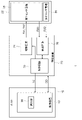
- FIG. 1 is a block diagram of the detection system 1 of the embodiment.
- the detection system 1 may detect a touch or the like on a display device such as a mobile device, or may detect a touch or the like without being combined with a display device.
- the detection system 1 comprises a host 10, a detection device 20 and a sensor 22.
- a host 10 controls a detection device 20 .
- the host 10 has a controller 12 .
- the control device 12 is, for example, a CPU and is also called a host CPU.
- the control device 12 has a selector 90 for selecting the operating mode of the detection system 1 .
- the selection unit 90 selects a first mode in which touch detection is performed or a second mode in which proximity detection is performed.
- the first mode may also be referred to as touch detection mode and the second mode may be referred to as proximity detection mode.
- the selection unit 90 selects the second mode until the proximity of an object is detected in a standby state in which no image is displayed on the display device, and selects the first mode when the proximity is detected in the second mode. do. In this case, the display device is released from the standby state and starts image display.
- the selector 90 may select the second mode when the conditions for transition to the standby state are satisfied in the first mode. Conditions for the selection unit 90 to select the first mode or the second mode can be appropriately determined according to the application of the detection system 1 . Details of the first mode and the second mode will be described later.
- the control device 12 supplies control data CD containing information on the operation mode to the detection device 20, and controls the detection device 20 based on this data.
- the sensor 22 is a sensor that detects the touch or proximity of an object to the display surface of the display device.
- Sensor 22 has a first sensor electrode 24 and a second sensor electrode 26 .
- FIG. 2 is a plan view schematically showing the sensor 22 of FIG. 1 arranged on the display device 40.
- FIG. FIG. 2 is a diagram of the display device 40 viewed from the observer side.
- the display device 40 displays an image on the display area 42 .
- the display device 40 is, for example, an out-sell type display device.
- the first sensor electrode 24 of the sensor 22 is arranged to overlap the display area 42 of the display device 40 .
- the first sensor electrodes 24 have a plurality of vertically extending first electrodes 30 and a plurality of horizontally extending second electrodes 32 .
- the plurality of first electrodes 30 are arranged horizontally at substantially equal intervals.
- the plurality of second electrodes 32 are arranged vertically at substantially equal intervals.
- the plurality of first electrodes 30 and the plurality of second electrodes 32 intersect.
- an electrode configuration of a known touch sensor can be adopted.
- the second sensor electrode 26 is arranged around the first sensor electrode 24, and is arranged below the first sensor electrode 24 in the example of FIG.
- the second sensor electrodes 26 do not overlap the display area 42 .
- the second sensor electrode 26 has a plurality of third electrodes 34 arranged horizontally.
- the second sensor electrode 26 may be arranged on the upper side, left side, or right side of the first sensor electrode 24 , or may be arranged so as to surround the first sensor electrode 24 .
- the detection device 20 is configured as an IC, for example, and performs touch detection and proximity detection using the sensor 22 according to control data CD from the host 10 .
- the detection device 20 comprises a control circuit 70 , a drive circuit 74 and a detection circuit 76 .
- the control circuit 70 is composed of, for example, a microcomputer, and controls signal generation timing of the drive circuit 74, touch or proximity detection timing of the detection circuit 76, and the like.
- the control circuit 70 controls the drive circuit 74 and the detection circuit 76 so that touch detection is performed by the mutual capacitance method in the first mode.
- a known technique can be used for touch detection.
- the drive circuit 74 Under the control of the control circuit 70, the drive circuit 74 generates the first drive signal TX1 in the first mode.
- the first drive signal TX1 can also be called a touch drive signal.
- the first drive signal TX1 may be a rectangular wave or a sine wave.
- the drive circuit 74 sequentially supplies the first drive signal TX1 to each of the plurality of second electrodes 32 of the first sensor electrodes 24 in chronological order. The drive circuit 74 does not supply the first drive signal TX1 to the first electrode 30 and the third electrode 34 in the first mode.
- the detection circuit 76 detects the touch of an object to the display device 40 in the first mode. In the first mode, the detection circuit 76, under the control of the control circuit 70, based on the first detection signal RX1 received from the first electrode 30 when the first drive signal TX1 is supplied to the second electrode 32, Detect object touches. The detection circuit 76 outputs information on the detected touch position to the control circuit 70 .
- control circuit 70 controls the drive circuit 74 and the detection circuit 76 so that proximity detection is performed by the mutual capacitance method.
- the drive circuit 74 In the second mode, the drive circuit 74 generates a second drive signal TX2 under the control of the control circuit 70, and applies the second drive signal TX2 to the first sensor electrodes 24, that is, the plurality of first electrodes 30 and the plurality of first electrodes 30 and the plurality of first electrodes 30, respectively. It is supplied to each of the two electrodes 32 .
- the drive circuit 74 does not supply the second drive signal TX2 to the second sensor electrodes 26 in the second mode.
- the waveform and amplitude of the second drive signal TX2 can be appropriately determined through experiments and simulations so as to obtain the desired proximity detection performance, and may be the same as or different from the waveform of the first drive signal TX1.
- the detection circuit 76 detects proximity of an object to the display device 40 in the second mode.
- the detection circuit 76 receives signals from the second sensor electrodes 26 when the second drive signal TX2 is supplied to the first sensor electrodes 24, that is, from the plurality of third electrodes 34 under the control of the control circuit 70. Based on the obtained second detection signal RX2, proximity of an object to a position corresponding to any third electrode 34 is detected.
- the detection circuit 76 outputs information on the detected proximity position to the control circuit 70 .
- the detection circuit 76 does not have to detect the proximity position, and may determine whether or not an object is approaching, and output information indicating that the proximity is detected to the control circuit 70 .
- the control circuit 70 derives the coordinate data TD of the touch position based on the touch position information from the detection circuit 76 and outputs the coordinate data TD to the control device 12 of the host 10 .
- the control circuit 70 derives the coordinate data TD of the proximity position based on the information of the proximity position from the detection circuit 76 and outputs the coordinate data TD to the control device 12 of the host 10 .
- the control device 12 executes various processes according to the coordinate data TD.
- the configuration of the control device 12 and the control circuit 70 can be realized by cooperation of hardware resources and software resources, or only by hardware resources.
- Analog devices, microcomputers, DSPs, ROMs, RAMs, FPGAs, and other LSIs can be used as hardware resources.
- Programs such as firmware can be used as software resources.
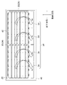
- FIG. 3 is a diagram illustrating operation of the sensor 22 of FIG. 1 in the second mode.
- the first electrode 30 and the second electrode 32 of the first sensor electrode 24 to which the second drive signal TX2 is supplied are labeled with "TX”, and the second sensor electrode 26 that outputs the second detection signal RX2 is shown as "TX”.
- the third electrode 34 is written as "RX”.
- An electric field is generated between the first sensor electrode 24 and the second sensor electrode 26 by supplying the second drive signal TX2. Schematic electric fields are indicated by arrows in FIG. Since the total area of the first sensor electrodes 24 is larger than the total area of the second sensor electrodes 26, it is possible to generate an electric field in a relatively wide area. That is, an electric field can be generated in the space on the front side of the display device 40 . Thus, objects in close proximity to the display surface will affect the electric field even if they are not in contact with the display surface.
- the second detection signal RX2 changes compared to when the object does not exist.
- the detection circuit 76 detects the proximity of the object by detecting the change. Even in the first mode, it can be detected that there is a touch even when the object does not touch the display surface and the object approaches the display surface to the extent that it causes an increase in detectable parasitic capacitance. It can detect proximity at a longer distance than the distance between the display surface and the object that can be detected in the mode.
- a known technique can be used for proximity detection using the second detection signal RX2.
- the detection circuit 76 can distinguish between the second detection signals RX2 received from the respective third electrodes 34. Therefore, in the second mode, the detection circuit 76 can detect the third electrode 34 to which an object approaches from among the plurality of third electrodes 34 . As a result, in addition to whether or not an object is approaching, it is possible to identify the approximate position where the object is approaching.
- the drive circuit 74 supplies the first sensor electrode 24 with the second drive signal TX2 having different frequencies in each of the plurality of detection periods. That is, the drive circuit 74 changes the frequency of the second drive signal TX2 every detection period.
- a plurality of detection periods can be collectively called a proximity detection period for detecting whether or not an object is approaching.
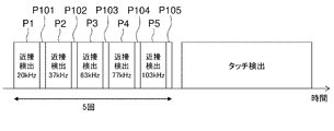
- FIG. 4 is a diagram illustrating multiple detection periods in the second mode of the detection system 1 of FIG.
- the first detection period P1, the first touch detection period P101, the second detection period P2, the second touch detection period P102, the third detection period P3, the third touch detection period P103, the fourth detection period P4, the The four touch detection periods P104, the fifth detection period P5, and the fifth touch detection period P105 are arranged in chronological order.
- a first touch detection period P101 to a fifth touch detection period P105 is a period in which proximity detection is stopped and touch detection is performed in the same manner as in the first mode. A touch is detected if an object touches the display surface even if it is not detected. When a touch is detected, touch detection in the first mode is continuously performed.
- the first touch detection period P101 to the fifth touch detection period P105 may not be provided, and in that case, the first detection period P1 to the fifth detection period P5 are arranged continuously.
- the number of detection periods is not limited to "5", and can be appropriately determined through experiments or simulations.
- the frequencies of the second drive signal TX2 supplied in each of the plurality of detection periods are different from each other by a natural number multiple.
- the frequency of the second drive signal TX2 is 20 kHz in the first detection period P1, 37 kHz in the second detection period P2, 63 kHz in the third detection period P3, 77 kHz in the fourth detection period P4, and 77 kHz in the fifth detection period. It is 103 kHz in period P5.
- the detection circuit 76 detects proximity of an object based on the second detection signal RX2 received from the second sensor electrode 26 in each of the plurality of detection periods. Specifically, the detection circuit 76 provisionally determines whether or not an object is approaching in each of a plurality of detection periods based on the second detection signal RX2 received from the second sensor electrode 26, When it is tentatively determined that an object is approaching in a number of detection periods or more, it is final determined that an object is approaching. If the detection circuit 76 does not provisionally determine that an object is approaching in a predetermined number or more of detection periods among the plurality of detection periods, the detection circuit 76 makes a final determination that an object is not approaching.
- the frequency and the predetermined number of the second drive signal TX2 can be appropriately determined through experiments and simulations so as to prevent erroneous detection of noise according to the noise in the environment in which the detection system 1 is used.
- the drive circuit 74 supplies the second drive signal TX2 in a plurality of detection periods of the next proximity detection period.
- the process of detecting proximity and the process of detecting proximity by the detection circuit 76 are executed again. That is, in the second mode, a series of provisional determinations and final determinations are repeatedly executed until it is determined that there is an approaching object.
- the detection circuit 76 uses the second detection signal RX2 received during five detection periods from the first detection period P1 to the fifth detection period P5, and detects the presence or absence of proximity when the fifth detection period P5 ends. is determined. For example, assuming that each detection period is 10 ms and each touch detection period is 2 ms, one determination of the presence or absence of proximity is completed in about 60 ms. For example, the predetermined number is "5", and when it is provisionally determined that there is proximity in each of the five detection periods, it is determined that there is proximity. In FIG. 4 , touch detection in the first mode is continuously performed after the final determination that there is proximity.
- the basic configuration of the detection system of the comparative example is the same as that of the detection system 1 of the embodiment.
- the frequency of drive signal TX2 is different from that in the embodiment.
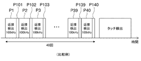
- FIG. 5 is a diagram explaining a plurality of detection periods in the second mode of the detection system of the comparative example.
- the period P39, the 39th touch detection period P139, the 40th detection period P40, and the 40th touch detection period P140 are arranged in chronological order.
- the number of detection periods is "40".
- the frequency of the second drive signal TX2 is the same in each detection period, eg, 100 kHz. Assuming that each detection period is 10 ms and each touch detection period is 2 ms as in FIG. 4, one determination of the presence or absence of proximity is completed in about 480 ms.
- the frequency of the second drive signal TX2 differs in each detection period.
- the number of detection periods tentatively determined to be present tends to be small. For example, if there is continuous noise that includes frequency components around 103 kHz and substantially no frequency components around 77 kHz, 63 kHz, 37 kHz, and 20 kHz, there is no proximity during the first detection period P1 to the fourth detection period P4. , and it can be provisionally determined that there is an approach only in the fifth detection period P5.
- the frequency of the second drive signal TX2 is 1/2, 1/4, etc.
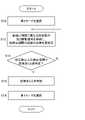
- FIG. 6 is a flow chart showing detection processing of the detection system 1 of FIG.
- the processing of FIG. 6 is started when the selection condition for the second mode is satisfied.
- the selection unit 90 selects the second mode (S10), the drive circuit 74 supplies the second drive signal TX2 having a different frequency in each detection period to the first sensor electrodes 24, and the detection circuit 76 supplies the second drive signal TX2 in each detection period. (S12). If it is not tentatively determined that there is proximity in the predetermined number of detection periods or more (N in S14), the process returns to S12. If it is provisionally determined that there is proximity in the predetermined number of detection periods or more (Y in S14), the detection circuit 76 makes a final determination that there is proximity (S16), and the selector 90 selects the first mode (S18). .
- the second drive signal TX2 having a frequency different from the previous five frequencies is applied. may be used to detect the presence or absence of proximity next time. For example, if the number of detection periods is '5', the first number may be '4' and the second number may be '5'. The first number and the second number can be appropriately determined through experiments and simulations.
- the drive circuit 74 detects the plurality of detection periods.
- the second drive signal TX2 may be supplied to the first sensor electrode 24 with a frequency different from the multiple frequencies of the second drive signal TX2 in the detection period and different in each of the next multiple detection periods. That is, the presence or absence of proximity is determined again using a frequency different from the frequency for which the provisional determination has been performed.
- the drive circuit 74 outputs the same plurality of frequencies as those of the plurality of detection periods.
- the second drive signal TX2 having a different frequency may be supplied to the first sensor electrode 24 in each of the next plurality of detection periods.
- the detection circuit 76 detects the proximity of the object based on the second detection signal RX2 received from the second sensor electrode 26 in each of the next plurality of detection periods.
- the detection circuit 76 makes a final determination that an object is approaching when it is tentatively determined that an object is approaching in a second number or more of detection periods among the plurality of detection periods.
- the drive circuit 74 detects the proximity of the object.
- the second drive signal TX2 may be supplied to the first sensor electrode 24 in each of the next plurality of detection periods at the frequency of the second drive signal TX2 in the detection period in which it is provisionally determined that there is no current.
- the frequency of 37 kHz supplied in the second detection period P2 A second drive signal TX2 is supplied in the next five detection periods.
- proximity can be detected in a shorter period of time and with higher accuracy. Further, since the frequency of the second drive signal TX2 supplied to each of the plurality of detection periods is different from each other by a natural number multiple, if there is noise including the frequency component of the second drive signal TX2, the frequency of the second drive signal TX2 may be reduced during the plurality of detection periods. Therefore, it is difficult to provisionally determine that there is proximity. Therefore, erroneous detection due to noise can be suppressed more reliably.
- touch detection using the mutual capacitance method in the first mode has been described, but touch detection may be performed using the self-capacitance method.
- an out-cell display device has been described in the embodiments, an in-cell display device may be used.
- the detection device 20 may be included in the host 10 . In these modifications, the degree of freedom in configuration of the detection system 1 can be improved.
- a detection device includes: a drive circuit that supplies a drive signal with a different frequency to the first sensor electrode in each of the plurality of detection periods; a detection circuit that detects proximity of an object based on detection signals received from second sensor electrodes arranged around the first sensor electrodes in each of the plurality of detection periods; Prepare. According to this aspect, the proximity of an object can be detected in a shorter time and with higher accuracy.
- the frequencies of the drive signals supplied to each of the plurality of detection periods may differ from each other by a natural number multiple. In this case, erroneous detection due to noise including the frequency component of the drive signal can be suppressed more reliably.
- the detection circuit is provisionally determining whether or not an object is approaching in each of the plurality of detection periods based on the detection signal received from the second sensor electrode; If it is tentatively determined that the object is approaching in a predetermined number or more of the plurality of detection periods, it may be determined that the object is approaching. In this case, the number of detection periods in which it is tentatively determined that there is proximity tends to be reduced due to noise including the frequency component of the drive signal, so erroneous detection can be suppressed.
- the detection circuit provisionally determines whether an object is approaching in each of the plurality of detection periods based on the detection signal received from the second sensor electrode; In the detection circuit, when it is provisionally determined that an object is approaching in detection periods equal to or greater than a predetermined first number and less than a predetermined second number among the plurality of detection periods, the drive circuit supplying a drive signal to the first sensor electrode in each of the next plurality of detection periods at the frequency of the drive signal in the detection period in which it was provisionally determined that there was no proximity of an object; The detection circuit may detect proximity of an object based on detection signals received from the second sensor electrodes in each of the next plurality of detection periods. In this case, when noise exists, it is easier to more reliably determine that an object is not approaching.
- the detection circuit provisionally determines whether an object is approaching in each of the plurality of detection periods based on the detection signal received from the second sensor electrode; In the detection circuit, when it is provisionally determined that an object is approaching in detection periods equal to or greater than a predetermined first number and less than a predetermined second number among the plurality of detection periods, the drive circuit supplying the first sensor electrode with a drive signal having a different frequency from the plurality of frequencies of the drive signal in the plurality of detection periods and having a different frequency in each of the next plurality of detection periods; The detection circuit may detect proximity of an object based on detection signals received from the second sensor electrodes in each of the next plurality of detection periods. In this case, when noise exists, it is easier to more reliably determine that an object is not approaching.
- the present disclosure can be used for detection devices having a proximity detection function.
Landscapes
- Engineering & Computer Science (AREA)
- General Engineering & Computer Science (AREA)
- Theoretical Computer Science (AREA)
- Human Computer Interaction (AREA)
- Physics & Mathematics (AREA)
- General Physics & Mathematics (AREA)
- Geophysics And Detection Of Objects (AREA)
- Electronic Switches (AREA)
Priority Applications (4)
| Application Number | Priority Date | Filing Date | Title |
|---|---|---|---|
| CN202180096138.4A CN117043727A (zh) | 2021-03-23 | 2021-09-29 | 检测装置 |
| DE112021007348.6T DE112021007348T5 (de) | 2021-03-23 | 2021-09-29 | Erkennungsvorrichtung, Erkennungssystem und Erkennungsverfahren |
| JP2023508441A JP7562226B2 (ja) | 2021-03-23 | 2021-09-29 | 検出装置、検出システム、および検出方法 |
| US18/371,143 US12164728B2 (en) | 2021-03-23 | 2023-09-21 | Detection device, detection system, and detection method |
Applications Claiming Priority (2)
| Application Number | Priority Date | Filing Date | Title |
|---|---|---|---|
| JP2021-048249 | 2021-03-23 | ||
| JP2021048249 | 2021-03-23 |
Related Child Applications (1)
| Application Number | Title | Priority Date | Filing Date |
|---|---|---|---|
| US18/371,143 Continuation US12164728B2 (en) | 2021-03-23 | 2023-09-21 | Detection device, detection system, and detection method |
Publications (1)
| Publication Number | Publication Date |
|---|---|
| WO2022201599A1 true WO2022201599A1 (ja) | 2022-09-29 |
Family
ID=83395256
Family Applications (1)
| Application Number | Title | Priority Date | Filing Date |
|---|---|---|---|
| PCT/JP2021/035883 Ceased WO2022201599A1 (ja) | 2021-03-23 | 2021-09-29 | 検出装置 |
Country Status (5)
| Country | Link |
|---|---|
| US (1) | US12164728B2 (enExample) |
| JP (1) | JP7562226B2 (enExample) |
| CN (1) | CN117043727A (enExample) |
| DE (1) | DE112021007348T5 (enExample) |
| WO (1) | WO2022201599A1 (enExample) |
Families Citing this family (1)
| Publication number | Priority date | Publication date | Assignee | Title |
|---|---|---|---|---|
| TW202401222A (zh) * | 2021-04-30 | 2024-01-01 | 日商阿爾卑斯阿爾派股份有限公司 | 鄰近檢測裝置 |
Citations (3)
| Publication number | Priority date | Publication date | Assignee | Title |
|---|---|---|---|---|
| JP2010015262A (ja) * | 2008-07-01 | 2010-01-21 | Seiko Instruments Inc | 静電検出装置及び静電検出方法 |
| JP2015046085A (ja) * | 2013-08-29 | 2015-03-12 | パナソニック株式会社 | タッチパネル装置 |
| JP2018060327A (ja) * | 2016-10-04 | 2018-04-12 | 株式会社ジャパンディスプレイ | 表示装置 |
Family Cites Families (5)
| Publication number | Priority date | Publication date | Assignee | Title |
|---|---|---|---|---|
| US9323398B2 (en) | 2009-07-10 | 2016-04-26 | Apple Inc. | Touch and hover sensing |
| US8816985B1 (en) * | 2012-09-20 | 2014-08-26 | Cypress Semiconductor Corporation | Methods and apparatus to detect a touch pattern |
| JP6143587B2 (ja) | 2013-07-11 | 2017-06-07 | 三菱電機株式会社 | タッチパネル、タッチパネル付き表示装置 |
| KR101859419B1 (ko) * | 2014-12-26 | 2018-05-23 | 엘지디스플레이 주식회사 | 터치 스크린 장치와 그의 구동방법 |
| JP7054618B2 (ja) | 2017-11-29 | 2022-04-14 | 株式会社ジャパンディスプレイ | 近接センサ |
-
2021
- 2021-09-29 CN CN202180096138.4A patent/CN117043727A/zh active Pending
- 2021-09-29 DE DE112021007348.6T patent/DE112021007348T5/de active Pending
- 2021-09-29 WO PCT/JP2021/035883 patent/WO2022201599A1/ja not_active Ceased
- 2021-09-29 JP JP2023508441A patent/JP7562226B2/ja active Active
-
2023
- 2023-09-21 US US18/371,143 patent/US12164728B2/en active Active
Patent Citations (3)
| Publication number | Priority date | Publication date | Assignee | Title |
|---|---|---|---|---|
| JP2010015262A (ja) * | 2008-07-01 | 2010-01-21 | Seiko Instruments Inc | 静電検出装置及び静電検出方法 |
| JP2015046085A (ja) * | 2013-08-29 | 2015-03-12 | パナソニック株式会社 | タッチパネル装置 |
| JP2018060327A (ja) * | 2016-10-04 | 2018-04-12 | 株式会社ジャパンディスプレイ | 表示装置 |
Also Published As
| Publication number | Publication date |
|---|---|
| JP7562226B2 (ja) | 2024-10-07 |
| JPWO2022201599A1 (enExample) | 2022-09-29 |
| US20240012519A1 (en) | 2024-01-11 |
| US12164728B2 (en) | 2024-12-10 |
| DE112021007348T5 (de) | 2024-01-04 |
| CN117043727A (zh) | 2023-11-10 |
Similar Documents
| Publication | Publication Date | Title |
|---|---|---|
| US20130027348A1 (en) | Touch sensing panel and device for detecting multi-touch signal | |
| US8963858B2 (en) | Use of resistive touch screen as a proximity sensor | |
| US9564894B2 (en) | Capacitive input device interference detection and operation | |
| WO2012135373A2 (en) | A dedicated user interface controller for feedback responses | |
| US20130155005A1 (en) | Touch display panel and driving method thereof | |
| JP5848589B2 (ja) | 位置検出装置および位置検出方法 | |
| US6590567B1 (en) | Coordinate input device | |
| EP2722733A1 (en) | Information processing device, information processing method, and program | |
| JP7562226B2 (ja) | 検出装置、検出システム、および検出方法 | |
| JP7117671B2 (ja) | 表示システムおよび制御方法 | |
| US9739995B2 (en) | Operating system and method for displaying an operating area | |
| JP4237741B2 (ja) | タッチパネル付き液晶型表示装置 | |
| JP5814704B2 (ja) | タッチパネルコントローラ、タッチパネルの制御方法、それを用いた入力装置および電子機器 | |
| US20160048259A1 (en) | Location based object classification | |
| JP7460871B2 (ja) | 表示システム、制御装置および制御方法 | |
| US10282021B2 (en) | Input object based increase in ground mass state | |
| JP2012128676A (ja) | タッチパネル | |
| JP7373755B2 (ja) | 表示システム、制御装置および制御方法 | |
| US20240329776A1 (en) | Input device | |
| US9134843B2 (en) | System and method for distinguishing input objects | |
| US11592925B1 (en) | Low latency input object detection under low ground mass condition | |
| US20250231639A1 (en) | Detection device | |
| US12287940B2 (en) | Noise measurements with a capacitance sensor | |
| US11921962B2 (en) | Sensor module and touch panel with first sensor array to detect non-contact touch and second sensor array to detect contacting touch | |
| US12271562B2 (en) | Multi-axis measurement with a capacitance module |
Legal Events
| Date | Code | Title | Description |
|---|---|---|---|
| 121 | Ep: the epo has been informed by wipo that ep was designated in this application |
Ref document number: 21933198 Country of ref document: EP Kind code of ref document: A1 |
|
| ENP | Entry into the national phase |
Ref document number: 2023508441 Country of ref document: JP Kind code of ref document: A |
|
| WWE | Wipo information: entry into national phase |
Ref document number: 202180096138.4 Country of ref document: CN |
|
| WWE | Wipo information: entry into national phase |
Ref document number: 112021007348 Country of ref document: DE |
|
| 122 | Ep: pct application non-entry in european phase |
Ref document number: 21933198 Country of ref document: EP Kind code of ref document: A1 |