WO2022201474A1 - 多心無反射終端部および光線路試験方法 - Google Patents
多心無反射終端部および光線路試験方法 Download PDFInfo
- Publication number
- WO2022201474A1 WO2022201474A1 PCT/JP2021/012731 JP2021012731W WO2022201474A1 WO 2022201474 A1 WO2022201474 A1 WO 2022201474A1 JP 2021012731 W JP2021012731 W JP 2021012731W WO 2022201474 A1 WO2022201474 A1 WO 2022201474A1
- Authority
- WO
- WIPO (PCT)
- Prior art keywords
- fiber
- connector
- core
- optical
- input
- Prior art date
- Legal status (The legal status is an assumption and is not a legal conclusion. Google has not performed a legal analysis and makes no representation as to the accuracy of the status listed.)
- Ceased
Links
Images


Classifications
-
- G—PHYSICS
- G02—OPTICS
- G02B—OPTICAL ELEMENTS, SYSTEMS OR APPARATUS
- G02B6/00—Light guides; Structural details of arrangements comprising light guides and other optical elements, e.g. couplings
- G02B6/24—Coupling light guides
- G02B6/36—Mechanical coupling means
- G02B6/38—Mechanical coupling means having fibre to fibre mating means
- G02B6/3807—Dismountable connectors, i.e. comprising plugs
- G02B6/381—Dismountable connectors, i.e. comprising plugs of the ferrule type, e.g. fibre ends embedded in ferrules, connecting a pair of fibres
- G02B6/3818—Dismountable connectors, i.e. comprising plugs of the ferrule type, e.g. fibre ends embedded in ferrules, connecting a pair of fibres of a low-reflection-loss type
- G02B6/3822—Dismountable connectors, i.e. comprising plugs of the ferrule type, e.g. fibre ends embedded in ferrules, connecting a pair of fibres of a low-reflection-loss type with beveled fibre ends
-
- G—PHYSICS
- G02—OPTICS
- G02B—OPTICAL ELEMENTS, SYSTEMS OR APPARATUS
- G02B6/00—Light guides; Structural details of arrangements comprising light guides and other optical elements, e.g. couplings
- G02B6/24—Coupling light guides
- G02B6/42—Coupling light guides with opto-electronic elements
- G02B6/43—Arrangements comprising a plurality of opto-electronic elements and associated optical interconnections
-
- G—PHYSICS
- G01—MEASURING; TESTING
- G01M—TESTING STATIC OR DYNAMIC BALANCE OF MACHINES OR STRUCTURES; TESTING OF STRUCTURES OR APPARATUS, NOT OTHERWISE PROVIDED FOR
- G01M11/00—Testing of optical apparatus; Testing structures by optical methods not otherwise provided for
- G01M11/30—Testing of optical devices, constituted by fibre optics or optical waveguides
- G01M11/31—Testing of optical devices, constituted by fibre optics or optical waveguides with a light emitter and a light receiver being disposed at the same side of a fibre or waveguide end-face, e.g. reflectometers
- G01M11/3109—Reflectometers detecting the back-scattered light in the time-domain, e.g. OTDR
- G01M11/3154—Details of the opto-mechanical connection, e.g. connector or repeater
-
- H—ELECTRICITY
- H04—ELECTRIC COMMUNICATION TECHNIQUE
- H04B—TRANSMISSION
- H04B10/00—Transmission systems employing electromagnetic waves other than radio-waves, e.g. infrared, visible or ultraviolet light, or employing corpuscular radiation, e.g. quantum communication
- H04B10/07—Arrangements for monitoring or testing transmission systems; Arrangements for fault measurement of transmission systems
- H04B10/071—Arrangements for monitoring or testing transmission systems; Arrangements for fault measurement of transmission systems using a reflected signal, e.g. using optical time domain reflectometers [OTDR]
-
- G—PHYSICS
- G02—OPTICS
- G02B—OPTICAL ELEMENTS, SYSTEMS OR APPARATUS
- G02B6/00—Light guides; Structural details of arrangements comprising light guides and other optical elements, e.g. couplings
- G02B6/24—Coupling light guides
- G02B6/26—Optical coupling means
- G02B6/28—Optical coupling means having data bus means, i.e. plural waveguides interconnected and providing an inherently bidirectional system by mixing and splitting signals
-
- G—PHYSICS
- G02—OPTICS
- G02B—OPTICAL ELEMENTS, SYSTEMS OR APPARATUS
- G02B6/00—Light guides; Structural details of arrangements comprising light guides and other optical elements, e.g. couplings
- G02B6/24—Coupling light guides
- G02B6/36—Mechanical coupling means
- G02B6/38—Mechanical coupling means having fibre to fibre mating means
- G02B6/3807—Dismountable connectors, i.e. comprising plugs
- G02B6/3873—Connectors using guide surfaces for aligning ferrule ends, e.g. tubes, sleeves, V-grooves, rods, pins, balls
- G02B6/3885—Multicore or multichannel optical connectors, i.e. one single ferrule containing more than one fibre, e.g. ribbon type
-
- G—PHYSICS
- G02—OPTICS
- G02B—OPTICAL ELEMENTS, SYSTEMS OR APPARATUS
- G02B6/00—Light guides; Structural details of arrangements comprising light guides and other optical elements, e.g. couplings
- G02B6/44—Mechanical structures for providing tensile strength and external protection for fibres, e.g. optical transmission cables
- G02B6/4439—Auxiliary devices
- G02B6/4471—Terminating devices ; Cable clamps
- G02B6/44715—Fan-out devices
Definitions
- the present disclosure relates to a multi-core non-reflection termination section connected to a connector section of an optical coupler attached to a tape fiber of an optical transmission system, and an optical line test method using the same.
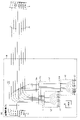
- FIGS 1 and 2 explain the configuration of the system that measures the optical fiber connecting the communication facility building and the user.
- the communication facility building 10 is configured with an OLT (Optical Line Terminal) 11 , an optical coupler 12 , an optical fiber switch 13 , an OTM (Optical Testing Module) 14 and an operation terminal 15 .
- OLT Optical Line Terminal
- OTM Optical Testing Module
- the OLT 11 and an ONU (Optical Network Unit) 21 on the user side are connected by an optical coupler 12 and a tape fiber 50 .
- the optical coupler 12 and the optical fiber switch 13 are connected by two sets of 8-core tape fibers 31 .
- the 8-core tape fiber 31 and the optical coupler 12 are collectively connected to 16-core by 16MT connectors (32a, 32b).
- the OTM 14 is composed of an OTDR (Optical Time Domain Reflectometer), a light measuring device such as a light source for contrast contrast, and a controller that controls them.
- OTDR Optical Time Domain Reflectometer
- a light measuring device such as a light source for contrast contrast
- a controller that controls them.
- the optical fiber switch 13 has a fiber array 13b in which a plurality of optical fibers are arranged in the width direction on the V-groove base 13a, and a single head fiber 13c that moves in the X-axis direction and the Y-axis direction. Connecting.
- the optical fiber switch 13 can move the head fiber 13c and select any one fiber from the optical fibers of the fiber array 13b (see Patent Documents 1 to 3, for example).
- the optical fiber switch 13 is filled with a refractive index matching material. Therefore, the optical fiber end of the fiber array 13b that is not connected to the head fiber 13c is also suppressed in reflection by the refractive index matching material, ensuring a return loss of 40 dB or more.
- the head fiber 13c of the optical fiber switch 13 moves in the X and Y directions on the V-groove base 13a to move the fiber array 13b. to the desired optical fiber.
- the optical transmission system is tested by injecting the optical fiber reference light or the OTDR test light from the OTM 14 through the optical coupler 12 into the tape fiber 50 (see, for example, Non-Patent Document 1).
- the optical fiber switch 13 and OTM 14 may not be installed in the communication facility building 10 .
- the 16MT connector 32a of the optical coupler 12 is in an open state, and the communication light from the OLT 11 or ONU 21 is reflected by the connector end face of the 16MT connector 32a of the optical coupler 12.
- the end face of the 16MT connector is polished at right angles, and the return loss of the 16MT connector may be about 15 dB.
- the reflected light generated by the 16MT connector may affect the communication quality between the OLT 11 and the ONU 21 .
- there is a risk that the communication light from the OLT 11 or the ONU 21 that is output from the end face of the 16MT connector 32a may accidentally enter the operator's eyes.
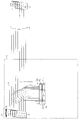
- FIG. 3 there is also known a multi-core non-reflection termination 60 that can be attached to the 16MT connector 32a and collectively suppress reflections occurring at the end faces of the 16MT connector 32a (see, for example, Patent Document 4). ).
- the non-reflection termination 60 protects the end face of the 16MT connector 32a and also prevents the communication light from the OLT 11 and ONU 21, which is output from the end face of the 16MT connector 32a, from entering the operator's eyes.
- the non-reflecting termination portion 60 when the non-reflecting termination portion 60 is attached in such a manner as to cover the entire 16MT connector 32a, the OTDR measurement for the tape fiber 50 cannot be performed. Therefore, as shown in FIG. 4, instead of attaching the non-reflective termination 60 to the 16MT connector 32a, a converter 61 is connected to convert the 16MT connector 32a into two sets of 8MT connectors 61b, and furthermore, the 8MT connector 61b FO (fan out) cord 62 is connected.
- the end portion of the 16MT connector 32a can be divided into single-core units, and reflection can be suppressed by attaching a single non-reflection terminal portion 63 to each end portion other than the end portion to be measured.
- any one of the tape fibers 50 can be measured by an OTDR or the like. Communication quality is not affected. In addition, it is possible to prevent the communication light from the OLT 11 and the ONU 21 output from the end face of the 16MT connector 32a from entering the operator's eyes.
- the converter 61, the FO cord 62, and the single-core non-reflection termination 63 are required for the configuration of FIG. In other words, in order to have the configuration of FIG. There is also a problem that a space for storage (hereinafter sometimes referred to as “storage space”) is also required.
- storage space a space for storage
- the present invention provides a multi-fiber non-reflection termination section that has little effect on an optical transmission system due to reflected light and that is composed of a small number of parts, and an optical line testing method using the same. intended to provide
- the multi-fiber non-reflection termination according to the present invention is such that the end face of the optical fiber on the side connected to the connector of the optical coupler is normally polished, but the end face on the opposite side is obliquely polished.
- the multi-core non-reflective termination according to the present invention is 2n (n is a natural number) optical fibers each having an end face that is vertically polished on one end side and an end face that is obliquely polished on the other end side; a 2n-fiber MT connector that collects 2n optical fibers and is attached to one end of the optical fibers; an n-fiber MT connector that divides the 2n optical fibers into two groups and is attached to the other end side of the optical fiber for each group; Prepare.
- This multi-fiber non-reflective termination is composed of only three parts (optical fiber, connector on the optical coupler side, connector on the anti-optical coupler side), and has a small number of components. Furthermore, since the end of the optical fiber on the anti-optical coupler side is obliquely polished, the light reflected at the end does not return to the OLT or ONU.
- the term "connector on the opposite side of the optical coupler" refers to the connector on the side of the optical fiber not connected to the optical coupler, which is the connector (73a, 73b) in FIGS. Therefore, the present invention can provide a multi-fiber non-reflection termination unit which has less influence on an optical transmission system due to reflected light and which is composed of a small number of parts.
- This multi-fiber non-reflective termination is preferably connected to the optical coupler as follows.
- the 2n-fiber MT connector is collectively connected to input/output terminals of 2n-fiber optical couplers provided on n-fiber tapes that connect n OLTs and n ONUs.
- One end of the n-fiber MT connector is connected by the 2n-fiber MT connector to the input/output terminal of the 2n-fiber input/output terminals of the optical coupler through which light can be input/output to/from the ONU.
- the other end of the n-fiber MT connector is connected by the 2n-fiber MT connector to the input/output terminal of the 2n-fiber input/output terminals of the optical coupler which can input/output light to/from the OLT. connected to the other end of the optical fiber connected to the optical fiber;
- the multi-fiber non-reflective termination according to the present invention further comprises an n-fiber FO (fan-out) code
- the FO code is an FO side n-core MT connector attached to the side where the n-cores are grouped and connected to the n-core MT connector; a single-core connector attached to each core on the branched side of the n-cores; has The end of each core is obliquely polished on both the FO side n-core MT connector side and the single-core connector side.
- the FO code can be used to perform an optical test for any route. It is desirable to use the FO code only when performing an optical test.
- the n-core MT connector of the multi-core non-reflective termination according to the present invention is characterized in that the entire connector ferrule including the other end of the optical fiber is obliquely polished.
- the multi-core non-reflection termination portion is a 2n optical coupler provided in an n-fiber tape fiber that connects n OLTs (n is a natural number) and n ONUs, respectively. and the 2n-fiber MT connector connects the one end to the input/output terminal of the 2n-fiber input/output terminals of the optical coupler that can input/output light to/from the ONU.
- One of the n-fiber MT connectors or the 2n-fiber MT connector connected to the other end of the optical fiber can input/output light to/from the OLT among the 2n-fiber input/output terminals of the optical coupler.
- An optical measuring instrument is connected to one of the other optical fibers of the n-core MT connector connected to the other end of the optical fiber whose one end is connected to the input/output end.
- optical line testing method when connecting the optical measuring instrument, connecting an FO-side n-core MT connector attached to a side of an n-core FO (fan-out) cord where the n-cores are grouped to the n-core MT connector; connecting the optical measuring instrument to one of the single-core connectors attached to each core on the side where the core is branched; characterized by
- the present invention can provide a multi-fiber non-reflection termination part that has little effect on an optical transmission system due to reflected light and is composed of a small number of parts, and an optical line test method using the same.
- FIG. 1 is a diagram illustrating the configuration of a system for measuring optical fibers connecting a communication facility building and users;
- FIG. 1 is a diagram illustrating the configuration of a system for measuring optical fibers connecting a communication facility building and users;
- FIG. 4 is a diagram for explaining a multi-fiber non-reflection terminal portion according to the present invention;
- FIG. 4 is a diagram for explaining a multi-fiber non-reflection terminal portion according to the present invention;
- FIG. 4 is a diagram for explaining a multi-fiber non-reflection terminal portion according to the present invention;
- FIG. 4 is a diagram for explaining a multi-fiber non-reflection terminal portion according to the present invention;
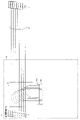
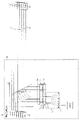
- the multi-core non-reflective termination 70 is 2n (n is a natural number) optical fibers 71 each having one end face that is vertically polished and the other end face that is obliquely polished; 2n optical fibers 71 are put together and a 2n-fiber MT connector 72 attached to one end of the optical fibers 71; 2n optical fibers 71 are divided into two groups, and n-core MT connectors (73a, 73b) attached to the other end side of the optical fibers 71 for each group; Prepare.
- the communication facility building 10 includes an OLT (Optical Line Terminal) 11 and an optical coupler 12 . Also, the OLT 11 and an ONU (Optical Network Unit) 21 on the user side are connected by an optical coupler 12 and a tape fiber 50 .
- OLT Optical Line Terminal
- ONU Optical Network Unit
- the optical coupler 12 and the multi-fiber non-reflection termination portion 70 are collectively connected with 16-fiber 16-fiber connectors (32a, 72). That is, the 2n-fiber MT connector 72 is connected to the 2n-fiber input/output end (MT connector) 32a of the optical coupler 12 provided in the n-fiber tape 50 that connects the plurality of n OLTs 11 and the plurality of n ONUs 21 respectively. Batch connection. One end of the n-core MT connector 73a is connected by the 2n-core MT connector 72 to an input/output end of the 2n-core input/output end (MT connector) 32a of the optical coupler 12 that can input/output light to/from the ONU 21.
- One end of the n-core MT connector 73b is connected by the 2n-core MT connector 72 to an input/output end of the 2n-core input/output end (MT connector) 32a of the optical coupler 12 that can input/output light to/from the OLT 11. It is connected to the other end of the optical fiber 71 .
- the communication light from the OLT 11 and the ONU 21 passes from the 16MT connector 32a of the optical coupler 12 through the 16MT-8MT conversion section (the portion from the MT connector 72 to the MT connectors (73a, 73b)), and is obliquely polished. reaches the end face of the optical fiber 71 on the 8MT connector 73 side. Since the end face is obliquely polished, even if the communication light is reflected, it does not return to the incident side, and the reflected light does not affect the communication quality between the OLT 11 and the ONU 21 .
- the angle at which the end surface of the optical fiber 71 is obliquely polished is preferably about 8 degrees.
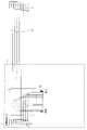
- the FO cord 82 is attached to the 8MT connector 73a explained in FIG. That is, the multi-fiber non-reflection termination unit 70 further includes an n-fiber FO cord 82, FO code 82 is an FO side n-core MT connector 81 attached to the side where the n-cores are grouped and connected to the n-core MT connector (73a or 73b); a single-core connector 83 attached to each core on the branched side of the n-cores; has The end of each core is obliquely polished on both the FO side n-core MT connector 81 side and the single-core connector 83 side.
- the FO cord 82 converts the 8MT connector 73a in which the end of the optical fiber 71 is obliquely polished into eight single-core connectors 83 in which the end is obliquely polished.
- the form shown in FIG. 5 is used. Only when measuring, the FO cord 82 can be attached as shown in FIG.
- the 8MT connector 73a having the obliquely polished end of the optical fiber 71 is simply connected to the 8MT connector 81 having the obliquely polished end.
- the polishing direction and angle of both are made to match so that a gap does not occur between the end of the optical fiber 71 and the end of the 8MT connector 81 when they are connected.
- non-reflective end portion 70 is short (for example, 5 cm or less), the storage space becomes unnecessary.
- the connector 32a of the coupler 12 is an example of a 16MT connector.
- a configuration of 16 single-fiber connectors is also possible.
- FIGS. 7 and 8 are diagrams for explaining the multi-core no-reflection termination section 70 of this embodiment.
- a cap 75 is attached to the end face of the open 8MT connector (73a, 73b).
- the cap 75 may damage the end face rather than protect it.
- the contact of the cap 75 with the end face of the optical fiber 71 changes the state of the obliquely polished end face, the communication light is reflected by the end face and returns to the incident side, and the reflected light travels between the OLT 11 and the ONU 21 . It may also affect communication quality.
- the entire connector ferrule 74 of the 8MT connector (73a, 73b) is obliquely polished. That is, the n-core MT connector (73a, 73b) is characterized in that the entire connector ferrule 74 including the other end of the optical fiber 71 is obliquely polished.
- the present embodiment can easily realize protection of the end face of the optical fiber 71 and safety measures for the operator.
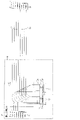
- FIG. 9 is a diagram for explaining the optical line testing method of this embodiment.
- This optical line testing method uses the multi-fiber non-reflection termination portion 70 described in Embodiment 1 as the 2n optical coupler 12 provided in the n-fiber tape fiber 50 that connects the n OLTs 11 and the n ONUs 21 respectively.
- step S01 The 2n-core input/output terminal ( one of the optical fibers 71 of the n-core MT connector 73b connected to the other end of the optical fiber 71 whose one end is connected to the input/output end capable of inputting/outputting light to/from the OLT 11 among the MT connectors 32a connecting the optical measuring instrument to (step S02) I do.
- step S02 connecting the FO-side n-core MT connector 81 attached to the side where the n-cores of the n-core FO (fan-out) cord 82 are grouped together to the n-core MT connector (73a or 73b) (step S02a; ), and connecting the optical measuring instrument to one of the single-core connectors 83 attached to the respective cores of the FO cord 82 on the side where the n-cores are branched (step S02b); is preferred.
Landscapes
- Physics & Mathematics (AREA)
- General Physics & Mathematics (AREA)
- Optics & Photonics (AREA)
- Signal Processing (AREA)
- Engineering & Computer Science (AREA)
- Computer Networks & Wireless Communication (AREA)
- Electromagnetism (AREA)
- Chemical & Material Sciences (AREA)
- Analytical Chemistry (AREA)
- Optical Communication System (AREA)
- Optical Fibers, Optical Fiber Cores, And Optical Fiber Bundles (AREA)
- Mechanical Coupling Of Light Guides (AREA)
- Optical Couplings Of Light Guides (AREA)
Priority Applications (3)
| Application Number | Priority Date | Filing Date | Title |
|---|---|---|---|
| PCT/JP2021/012731 WO2022201474A1 (ja) | 2021-03-25 | 2021-03-25 | 多心無反射終端部および光線路試験方法 |
| US18/277,753 US20240126030A1 (en) | 2021-03-25 | 2021-03-25 | Multi-center non-reflective termination and optical line test method |
| JP2023508354A JP7525053B2 (ja) | 2021-03-25 | 2021-03-25 | 多心無反射終端部および光線路試験方法 |
Applications Claiming Priority (1)
| Application Number | Priority Date | Filing Date | Title |
|---|---|---|---|
| PCT/JP2021/012731 WO2022201474A1 (ja) | 2021-03-25 | 2021-03-25 | 多心無反射終端部および光線路試験方法 |
Publications (1)
| Publication Number | Publication Date |
|---|---|
| WO2022201474A1 true WO2022201474A1 (ja) | 2022-09-29 |
Family
ID=83396644
Family Applications (1)
| Application Number | Title | Priority Date | Filing Date |
|---|---|---|---|
| PCT/JP2021/012731 Ceased WO2022201474A1 (ja) | 2021-03-25 | 2021-03-25 | 多心無反射終端部および光線路試験方法 |
Country Status (3)
| Country | Link |
|---|---|
| US (1) | US20240126030A1 (enExample) |
| JP (1) | JP7525053B2 (enExample) |
| WO (1) | WO2022201474A1 (enExample) |
Cited By (1)
| Publication number | Priority date | Publication date | Assignee | Title |
|---|---|---|---|---|
| WO2024172092A1 (ja) * | 2023-02-15 | 2024-08-22 | 住友電気工業株式会社 | 空間チャネル間クロストーク測定方法および空間チャネル間クロストーク測定装置 |
Citations (5)
| Publication number | Priority date | Publication date | Assignee | Title |
|---|---|---|---|---|
| JPH0540210A (ja) * | 1991-08-06 | 1993-02-19 | Furukawa Electric Co Ltd:The | 光分岐線路の終端装置 |
| JPH0618744A (ja) * | 1992-04-27 | 1994-01-28 | Nippon Telegr & Teleph Corp <Ntt> | 光分岐ユニット及びこのユニットに用いる導波路型光カプラモジュール |
| JP2002139631A (ja) * | 2000-11-02 | 2002-05-17 | Sumitomo Electric Ind Ltd | 多心/単心コネクタ変換装置 |
| US20110103803A1 (en) * | 2009-10-29 | 2011-05-05 | Paul Kolesar | Optical Fiber Array Connectivity System for Multiple Transceivers and/or Multiple Trunk Cables |
| JP2012530936A (ja) * | 2009-06-17 | 2012-12-06 | コーニング ケーブル システムズ リミテッド ライアビリティ カンパニー | 高速データレート伝送システム用光相互接続 |
Family Cites Families (8)
| Publication number | Priority date | Publication date | Assignee | Title |
|---|---|---|---|---|
| JP2714733B2 (ja) * | 1992-01-20 | 1998-02-16 | 日本電信電話株式会社 | 光線路試験方式 |
| JP3253472B2 (ja) * | 1994-12-09 | 2002-02-04 | 株式会社フジクラ | 光ファイバの無反射終端部 |
| JPH08327830A (ja) * | 1995-06-02 | 1996-12-13 | Sumitomo Electric Ind Ltd | 光部品収納トレイ |
| JP3042595B2 (ja) * | 1995-11-20 | 2000-05-15 | 古河電気工業株式会社 | 光線路保守システム |
| EP2296024A4 (en) * | 2008-06-18 | 2012-02-01 | Tomoegawa Co Ltd | OPTICAL TRANSMISSION MEDIUM, SLEEVE, OPTICAL CONNECTOR, OPTICAL STRUCTURE AND OPTICAL DEVICE |
| US8009959B2 (en) * | 2009-06-17 | 2011-08-30 | Corning Cable Systems Llc | Optical interconnection methods for high-speed data-rate optical transport systems |
| US20160091674A1 (en) * | 2014-09-29 | 2016-03-31 | Virtual Instruments Corporation | Angled-polished connector terminations in multimode applications |
| US20190339458A1 (en) * | 2018-05-03 | 2019-11-07 | Panduit Corp. | Angle polished multi-fiber connector |
-
2021
- 2021-03-25 JP JP2023508354A patent/JP7525053B2/ja active Active
- 2021-03-25 WO PCT/JP2021/012731 patent/WO2022201474A1/ja not_active Ceased
- 2021-03-25 US US18/277,753 patent/US20240126030A1/en active Pending
Patent Citations (5)
| Publication number | Priority date | Publication date | Assignee | Title |
|---|---|---|---|---|
| JPH0540210A (ja) * | 1991-08-06 | 1993-02-19 | Furukawa Electric Co Ltd:The | 光分岐線路の終端装置 |
| JPH0618744A (ja) * | 1992-04-27 | 1994-01-28 | Nippon Telegr & Teleph Corp <Ntt> | 光分岐ユニット及びこのユニットに用いる導波路型光カプラモジュール |
| JP2002139631A (ja) * | 2000-11-02 | 2002-05-17 | Sumitomo Electric Ind Ltd | 多心/単心コネクタ変換装置 |
| JP2012530936A (ja) * | 2009-06-17 | 2012-12-06 | コーニング ケーブル システムズ リミテッド ライアビリティ カンパニー | 高速データレート伝送システム用光相互接続 |
| US20110103803A1 (en) * | 2009-10-29 | 2011-05-05 | Paul Kolesar | Optical Fiber Array Connectivity System for Multiple Transceivers and/or Multiple Trunk Cables |
Cited By (1)
| Publication number | Priority date | Publication date | Assignee | Title |
|---|---|---|---|---|
| WO2024172092A1 (ja) * | 2023-02-15 | 2024-08-22 | 住友電気工業株式会社 | 空間チャネル間クロストーク測定方法および空間チャネル間クロストーク測定装置 |
Also Published As
| Publication number | Publication date |
|---|---|
| JPWO2022201474A1 (enExample) | 2022-09-29 |
| US20240126030A1 (en) | 2024-04-18 |
| JP7525053B2 (ja) | 2024-07-30 |
Similar Documents
| Publication | Publication Date | Title |
|---|---|---|
| Takahashi et al. | Uncoupled 4-core fibre with ultra-low loss and low inter core crosstalk | |
| EP2264420A1 (en) | Optical reflective marker adaptor for a patch cord in OTDR applications | |
| JP6636273B2 (ja) | マルチコア光ファイバの接続方法 | |
| CN104932061B (zh) | 光纤连接器 | |
| EP3887792B1 (en) | Large core apparatus for measuring optical power in multifiber cables | |
| US20220038177A1 (en) | Optical-fiber device for one-cord reference optical power loss measurement | |
| Xiong et al. | Low loss ultra-small core pitch all-fiber fan-in/fan-out device for coupled-core multicore fibers | |
| JP7525053B2 (ja) | 多心無反射終端部および光線路試験方法 | |
| Kikuchi et al. | Low insertion loss and high return loss fiber bundle fan-in/fan-out for four-core multi-core fiber | |
| Nagase | Optical connectivities for multicore fiber | |
| Grüner-Nielsen et al. | Photonic-lantern-based MDM devices | |
| Takahashi et al. | Fan-in/Fan-out for multicore fibers | |
| Asada et al. | Next generation multi-fiber ferrule using 165 micron pitch optical fiber | |
| Nagase et al. | Hollow-core fiber connector | |
| JP7476986B2 (ja) | 光クロスコネクト装置 | |
| Nagase | How to connect multicore and multimode fibers | |
| Tekippe et al. | Production, performance, and reliability of fused couplers | |
| Fukai et al. | Multi-Fiber Cylindrical Ferrule for Remote Rotary Optical Fiber Switching | |
| Yang et al. | Fused tapered fan-in/fan-out device of 6-mode 7-core fiber based on OM3 multimode fiber | |
| Dalgleish | Splices, connectors, and power couplers for field and office use | |
| Kamimura et al. | Return Loss Measurement Procedure for Multicore Fiber Connectors | |
| Sasaki et al. | High Core Density 19-Core Fiber Connector | |
| Kihara | Optical performance analysis of single-mode fiber connections | |
| Wood et al. | 3-Port Fibre Optic Beam Splitters for Space Division Multiplexed Systems | |
| Kihara et al. | Analysis on performance deterioration of optical fiber joints with mixture of refractive index matching material and air-filled gaps |
Legal Events
| Date | Code | Title | Description |
|---|---|---|---|
| 121 | Ep: the epo has been informed by wipo that ep was designated in this application |
Ref document number: 21933079 Country of ref document: EP Kind code of ref document: A1 |
|
| ENP | Entry into the national phase |
Ref document number: 2023508354 Country of ref document: JP Kind code of ref document: A |
|
| WWE | Wipo information: entry into national phase |
Ref document number: 18277753 Country of ref document: US |
|
| NENP | Non-entry into the national phase |
Ref country code: DE |
|
| 122 | Ep: pct application non-entry in european phase |
Ref document number: 21933079 Country of ref document: EP Kind code of ref document: A1 |