WO2022201381A1 - 鋼材 - Google Patents
鋼材 Download PDFInfo
- Publication number
- WO2022201381A1 WO2022201381A1 PCT/JP2021/012350 JP2021012350W WO2022201381A1 WO 2022201381 A1 WO2022201381 A1 WO 2022201381A1 JP 2021012350 W JP2021012350 W JP 2021012350W WO 2022201381 A1 WO2022201381 A1 WO 2022201381A1
- Authority
- WO
- WIPO (PCT)
- Prior art keywords
- steel material
- steel
- content
- rolling
- shaving
- Prior art date
- Legal status (The legal status is an assumption and is not a legal conclusion. Google has not performed a legal analysis and makes no representation as to the accuracy of the status listed.)
- Ceased
Links
Images


Classifications
-
- C—CHEMISTRY; METALLURGY
- C22—METALLURGY; FERROUS OR NON-FERROUS ALLOYS; TREATMENT OF ALLOYS OR NON-FERROUS METALS
- C22C—ALLOYS
- C22C38/00—Ferrous alloys, e.g. steel alloys
- C22C38/18—Ferrous alloys, e.g. steel alloys containing chromium
- C22C38/24—Ferrous alloys, e.g. steel alloys containing chromium with vanadium
-
- C—CHEMISTRY; METALLURGY
- C21—METALLURGY OF IRON
- C21D—MODIFYING THE PHYSICAL STRUCTURE OF FERROUS METALS; GENERAL DEVICES FOR HEAT TREATMENT OF FERROUS OR NON-FERROUS METALS OR ALLOYS; MAKING METAL MALLEABLE, e.g. BY DECARBURISATION OR TEMPERING
- C21D7/00—Modifying the physical properties of iron or steel by deformation
- C21D7/13—Modifying the physical properties of iron or steel by deformation by hot working
-
- C—CHEMISTRY; METALLURGY
- C21—METALLURGY OF IRON
- C21D—MODIFYING THE PHYSICAL STRUCTURE OF FERROUS METALS; GENERAL DEVICES FOR HEAT TREATMENT OF FERROUS OR NON-FERROUS METALS OR ALLOYS; MAKING METAL MALLEABLE, e.g. BY DECARBURISATION OR TEMPERING
- C21D1/00—General methods or devices for heat treatment, e.g. annealing, hardening, quenching or tempering
- C21D1/02—Hardening articles or materials formed by forging or rolling, with no further heating beyond that required for the formation
-
- C—CHEMISTRY; METALLURGY
- C21—METALLURGY OF IRON
- C21D—MODIFYING THE PHYSICAL STRUCTURE OF FERROUS METALS; GENERAL DEVICES FOR HEAT TREATMENT OF FERROUS OR NON-FERROUS METALS OR ALLOYS; MAKING METAL MALLEABLE, e.g. BY DECARBURISATION OR TEMPERING
- C21D1/00—General methods or devices for heat treatment, e.g. annealing, hardening, quenching or tempering
- C21D1/84—Controlled slow cooling
-
- C—CHEMISTRY; METALLURGY
- C21—METALLURGY OF IRON
- C21D—MODIFYING THE PHYSICAL STRUCTURE OF FERROUS METALS; GENERAL DEVICES FOR HEAT TREATMENT OF FERROUS OR NON-FERROUS METALS OR ALLOYS; MAKING METAL MALLEABLE, e.g. BY DECARBURISATION OR TEMPERING
- C21D9/00—Heat treatment, e.g. annealing, hardening, quenching or tempering, adapted for particular articles; Furnaces therefor
- C21D9/52—Heat treatment, e.g. annealing, hardening, quenching or tempering, adapted for particular articles; Furnaces therefor for wires; for strips ; for rods of unlimited length
- C21D9/525—Heat treatment, e.g. annealing, hardening, quenching or tempering, adapted for particular articles; Furnaces therefor for wires; for strips ; for rods of unlimited length for wire, for rods
-
- C—CHEMISTRY; METALLURGY
- C21—METALLURGY OF IRON
- C21D—MODIFYING THE PHYSICAL STRUCTURE OF FERROUS METALS; GENERAL DEVICES FOR HEAT TREATMENT OF FERROUS OR NON-FERROUS METALS OR ALLOYS; MAKING METAL MALLEABLE, e.g. BY DECARBURISATION OR TEMPERING
- C21D9/00—Heat treatment, e.g. annealing, hardening, quenching or tempering, adapted for particular articles; Furnaces therefor
- C21D9/52—Heat treatment, e.g. annealing, hardening, quenching or tempering, adapted for particular articles; Furnaces therefor for wires; for strips ; for rods of unlimited length
- C21D9/54—Furnaces for treating strips or wire
- C21D9/56—Continuous furnaces for strip or wire
- C21D9/573—Continuous furnaces for strip or wire with cooling
- C21D9/5732—Continuous furnaces for strip or wire with cooling of wires; of rods
-
- C—CHEMISTRY; METALLURGY
- C22—METALLURGY; FERROUS OR NON-FERROUS ALLOYS; TREATMENT OF ALLOYS OR NON-FERROUS METALS
- C22C—ALLOYS
- C22C38/00—Ferrous alloys, e.g. steel alloys
-
- C—CHEMISTRY; METALLURGY
- C22—METALLURGY; FERROUS OR NON-FERROUS ALLOYS; TREATMENT OF ALLOYS OR NON-FERROUS METALS
- C22C—ALLOYS
- C22C38/00—Ferrous alloys, e.g. steel alloys
- C22C38/001—Ferrous alloys, e.g. steel alloys containing N
-
- C—CHEMISTRY; METALLURGY
- C22—METALLURGY; FERROUS OR NON-FERROUS ALLOYS; TREATMENT OF ALLOYS OR NON-FERROUS METALS
- C22C—ALLOYS
- C22C38/00—Ferrous alloys, e.g. steel alloys
- C22C38/002—Ferrous alloys, e.g. steel alloys containing In, Mg, or other elements not provided for in one single group C22C38/001 - C22C38/60
-
- C—CHEMISTRY; METALLURGY
- C22—METALLURGY; FERROUS OR NON-FERROUS ALLOYS; TREATMENT OF ALLOYS OR NON-FERROUS METALS
- C22C—ALLOYS
- C22C38/00—Ferrous alloys, e.g. steel alloys
- C22C38/02—Ferrous alloys, e.g. steel alloys containing silicon
-
- C—CHEMISTRY; METALLURGY
- C22—METALLURGY; FERROUS OR NON-FERROUS ALLOYS; TREATMENT OF ALLOYS OR NON-FERROUS METALS
- C22C—ALLOYS
- C22C38/00—Ferrous alloys, e.g. steel alloys
- C22C38/04—Ferrous alloys, e.g. steel alloys containing manganese
-
- C—CHEMISTRY; METALLURGY
- C22—METALLURGY; FERROUS OR NON-FERROUS ALLOYS; TREATMENT OF ALLOYS OR NON-FERROUS METALS
- C22C—ALLOYS
- C22C38/00—Ferrous alloys, e.g. steel alloys
- C22C38/06—Ferrous alloys, e.g. steel alloys containing aluminium
-
- C—CHEMISTRY; METALLURGY
- C22—METALLURGY; FERROUS OR NON-FERROUS ALLOYS; TREATMENT OF ALLOYS OR NON-FERROUS METALS
- C22C—ALLOYS
- C22C38/00—Ferrous alloys, e.g. steel alloys
- C22C38/18—Ferrous alloys, e.g. steel alloys containing chromium
- C22C38/22—Ferrous alloys, e.g. steel alloys containing chromium with molybdenum or tungsten
-
- C—CHEMISTRY; METALLURGY
- C22—METALLURGY; FERROUS OR NON-FERROUS ALLOYS; TREATMENT OF ALLOYS OR NON-FERROUS METALS
- C22C—ALLOYS
- C22C38/00—Ferrous alloys, e.g. steel alloys
- C22C38/18—Ferrous alloys, e.g. steel alloys containing chromium
- C22C38/30—Ferrous alloys, e.g. steel alloys containing chromium with cobalt
-
- C—CHEMISTRY; METALLURGY
- C22—METALLURGY; FERROUS OR NON-FERROUS ALLOYS; TREATMENT OF ALLOYS OR NON-FERROUS METALS
- C22C—ALLOYS
- C22C38/00—Ferrous alloys, e.g. steel alloys
- C22C38/18—Ferrous alloys, e.g. steel alloys containing chromium
- C22C38/40—Ferrous alloys, e.g. steel alloys containing chromium with nickel
- C22C38/54—Ferrous alloys, e.g. steel alloys containing chromium with nickel with boron
-
- C—CHEMISTRY; METALLURGY
- C21—METALLURGY OF IRON
- C21D—MODIFYING THE PHYSICAL STRUCTURE OF FERROUS METALS; GENERAL DEVICES FOR HEAT TREATMENT OF FERROUS OR NON-FERROUS METALS OR ALLOYS; MAKING METAL MALLEABLE, e.g. BY DECARBURISATION OR TEMPERING
- C21D1/00—General methods or devices for heat treatment, e.g. annealing, hardening, quenching or tempering
- C21D1/18—Hardening; Quenching with or without subsequent tempering
- C21D1/25—Hardening, combined with annealing between 300 degrees Celsius and 600 degrees Celsius, i.e. heat refining ("Vergüten")
-
- C—CHEMISTRY; METALLURGY
- C21—METALLURGY OF IRON
- C21D—MODIFYING THE PHYSICAL STRUCTURE OF FERROUS METALS; GENERAL DEVICES FOR HEAT TREATMENT OF FERROUS OR NON-FERROUS METALS OR ALLOYS; MAKING METAL MALLEABLE, e.g. BY DECARBURISATION OR TEMPERING
- C21D1/00—General methods or devices for heat treatment, e.g. annealing, hardening, quenching or tempering
- C21D1/26—Methods of annealing
- C21D1/30—Stress-relieving
-
- C—CHEMISTRY; METALLURGY
- C21—METALLURGY OF IRON
- C21D—MODIFYING THE PHYSICAL STRUCTURE OF FERROUS METALS; GENERAL DEVICES FOR HEAT TREATMENT OF FERROUS OR NON-FERROUS METALS OR ALLOYS; MAKING METAL MALLEABLE, e.g. BY DECARBURISATION OR TEMPERING
- C21D2211/00—Microstructure comprising significant phases
- C21D2211/004—Dispersions; Precipitations
-
- C—CHEMISTRY; METALLURGY
- C21—METALLURGY OF IRON
- C21D—MODIFYING THE PHYSICAL STRUCTURE OF FERROUS METALS; GENERAL DEVICES FOR HEAT TREATMENT OF FERROUS OR NON-FERROUS METALS OR ALLOYS; MAKING METAL MALLEABLE, e.g. BY DECARBURISATION OR TEMPERING
- C21D2211/00—Microstructure comprising significant phases
- C21D2211/009—Pearlite
-
- C—CHEMISTRY; METALLURGY
- C21—METALLURGY OF IRON
- C21D—MODIFYING THE PHYSICAL STRUCTURE OF FERROUS METALS; GENERAL DEVICES FOR HEAT TREATMENT OF FERROUS OR NON-FERROUS METALS OR ALLOYS; MAKING METAL MALLEABLE, e.g. BY DECARBURISATION OR TEMPERING
- C21D2261/00—Machining or cutting being involved
-
- C—CHEMISTRY; METALLURGY
- C21—METALLURGY OF IRON
- C21D—MODIFYING THE PHYSICAL STRUCTURE OF FERROUS METALS; GENERAL DEVICES FOR HEAT TREATMENT OF FERROUS OR NON-FERROUS METALS OR ALLOYS; MAKING METAL MALLEABLE, e.g. BY DECARBURISATION OR TEMPERING
- C21D7/00—Modifying the physical properties of iron or steel by deformation
- C21D7/02—Modifying the physical properties of iron or steel by deformation by cold working
- C21D7/04—Modifying the physical properties of iron or steel by deformation by cold working of the surface
- C21D7/06—Modifying the physical properties of iron or steel by deformation by cold working of the surface by shot-peening or the like
-
- C—CHEMISTRY; METALLURGY
- C21—METALLURGY OF IRON
- C21D—MODIFYING THE PHYSICAL STRUCTURE OF FERROUS METALS; GENERAL DEVICES FOR HEAT TREATMENT OF FERROUS OR NON-FERROUS METALS OR ALLOYS; MAKING METAL MALLEABLE, e.g. BY DECARBURISATION OR TEMPERING
- C21D7/00—Modifying the physical properties of iron or steel by deformation
- C21D7/02—Modifying the physical properties of iron or steel by deformation by cold working
- C21D7/10—Modifying the physical properties of iron or steel by deformation by cold working of the whole cross-section, e.g. of concrete reinforcing bars
-
- C—CHEMISTRY; METALLURGY
- C21—METALLURGY OF IRON
- C21D—MODIFYING THE PHYSICAL STRUCTURE OF FERROUS METALS; GENERAL DEVICES FOR HEAT TREATMENT OF FERROUS OR NON-FERROUS METALS OR ALLOYS; MAKING METAL MALLEABLE, e.g. BY DECARBURISATION OR TEMPERING
- C21D8/00—Modifying the physical properties of ferrous metals or ferrous alloys by deformation combined with, or followed by, heat treatment
- C21D8/06—Modifying the physical properties of ferrous metals or ferrous alloys by deformation combined with, or followed by, heat treatment during manufacturing of rods or wires
-
- C—CHEMISTRY; METALLURGY
- C21—METALLURGY OF IRON
- C21D—MODIFYING THE PHYSICAL STRUCTURE OF FERROUS METALS; GENERAL DEVICES FOR HEAT TREATMENT OF FERROUS OR NON-FERROUS METALS OR ALLOYS; MAKING METAL MALLEABLE, e.g. BY DECARBURISATION OR TEMPERING
- C21D9/00—Heat treatment, e.g. annealing, hardening, quenching or tempering, adapted for particular articles; Furnaces therefor
- C21D9/02—Heat treatment, e.g. annealing, hardening, quenching or tempering, adapted for particular articles; Furnaces therefor for springs
-
- Y—GENERAL TAGGING OF NEW TECHNOLOGICAL DEVELOPMENTS; GENERAL TAGGING OF CROSS-SECTIONAL TECHNOLOGIES SPANNING OVER SEVERAL SECTIONS OF THE IPC; TECHNICAL SUBJECTS COVERED BY FORMER USPC CROSS-REFERENCE ART COLLECTIONS [XRACs] AND DIGESTS
- Y02—TECHNOLOGIES OR APPLICATIONS FOR MITIGATION OR ADAPTATION AGAINST CLIMATE CHANGE
- Y02P—CLIMATE CHANGE MITIGATION TECHNOLOGIES IN THE PRODUCTION OR PROCESSING OF GOODS
- Y02P10/00—Technologies related to metal processing
- Y02P10/20—Recycling
Definitions
- the present invention relates to a steel material, and more particularly to a steel material that is used as a material for springs such as damper springs and valve springs.
- Springs are used extensively in automobiles and general machinery.
- damper springs absorb external shocks or vibrations.
- Damper springs are used, for example, in torque converters that transmit the power of a motor vehicle to a transmission. Damper springs are required to have high fatigue strength.
- valve springs regulate the opening and closing of valves in the devices of automobiles and general machinery. Valve springs are used, for example, to control the opening and closing of intake and exhaust valves of internal combustion engines (engines) of automobiles. Therefore, like the damper spring, the valve spring is also required to have high fatigue strength.
- the manufacturing process of springs represented by damper springs and valve springs is as follows. Prepare the steel (wire rod) that will be the material of the spring. A shaving (peeling) process is performed on the steel material.
- the shaving process means a process of passing a steel material (wire material) through a shaving die and scraping off (peeling) the entire surface (peripheral surface) of the steel material. By performing a shaving treatment, surface flaws and decarburized layers of the steel material are removed.
- the steel material after the shaving process is subjected to wire drawing to make a steel wire.
- the steel wire is subjected to refining treatment (quenching and tempering).
- Cold coiling is performed on the steel wire after the temper treatment to produce a coil-shaped intermediate steel material.
- the intermediate steel material is subjected to strain relief annealing.
- Surface hardening heat treatment (nitriding treatment, etc.) is performed on the intermediate steel material after strain relief annealing, if necessary.
- the intermediate steel material is subjected to shot peening to impart compressive residual stress to the surface layer.
- a spring is manufactured by the manufacturing process described above.
- Patent Document 1 Japanese Patent Application Laid-Open No. 7-173577
- Patent Document 2 Japanese Patent Application Laid-Open No. 2007-327084
- Patent Literature 1 describes that the steel material thus has a high strength of 1900 MPa or more after quenching and tempering and has excellent corrosion resistance.
- the wire disclosed in Patent Document 2 has, in mass %, C: 0.6 to 1.1%, Si: 0.1 to 2.0%, Mn: 0.1 to 1%, P: 0.020 % or less (not including 0%), S: 0.020% or less (not including 0%), N: 0.006% or less (not including 0%), Al: 0.03% or less (0% ), O: 0.003% or less (not including 0%), and the balance consists of Fe and unavoidable impurities.
- This wire further has a pearlite structure with a second phase ferrite area ratio of 11.0% or less and a pearlite lamellar spacing of 120 ⁇ m or more. According to the patent document, due to the above configuration, this wire rod is less likely to break even though the wire drawing speed is increased and the area reduction rate is increased, and the life of the dies used for wire drawing can be extended. 2 is described.
- defects caused by shaving such as “burrs”, “pluck” and “cracks” (hereinafter referred to as “shaving-induced defects") may occur on the surface of the steel material after shaving.
- burrs are flaws caused by part of chips generated on the steel material surface during shaving treatment remaining on the steel material surface.
- a “pluck” is a flaw that occurs when a part of the steel material surface near the base of the chip is ripped off when the chip separates from the steel material surface.
- a "crack” is a flaw caused by cracking in a portion of the steel material surface near the root of the chip when the chip separates from the steel material surface.
- the surface of the steel material with shaving-induced flaws has reduced smoothness and is in a rough state.
- a spring manufactured using a steel material having a rough surface has a reduced fatigue strength. Therefore, in the steel material used as the raw material of the spring, it is required to suppress roughening of the surface of the steel material after the shaving treatment is performed.
- Patent Documents 1 and 2 do not disclose any technique for suppressing roughening of the steel material after shaving.
- An object of the present disclosure is to provide a steel material that can suppress surface roughness when shaving is performed.
- the steel material of this embodiment is The chemical composition, in mass %, C: 0.50 to 0.80%, Si: 1.20 to 2.90%, Mn: 0.25-1.00%, Cr: 0.40 to 1.90%, V: 0.05 to 0.60%, P: 0.020% or less, S: 0.020% or less, N: 0.0100% or less, Mo: 0-0.50%, Nb: 0 to 0.050%, W: 0 to 0.60%, Ni: 0 to 0.50%, Co: 0-0.30%, B: 0 to 0.0050%, Cu: 0-0.050%, Al: 0 to 0.0050%, and Ti: 0 to 0.050%, containing The balance consists of Fe and impurities, In the microstructure of the steel material, the pearlite area ratio is 90% or more, In the ferrite in the pearlite, The number density of V-based precipitates having a maximum diameter of 2 to 20 nm is 3000 to 80000/ ⁇ m 3 .
- the steel material according to the present disclosure can suppress roughening of the surface of the steel material when shaving treatment is performed.
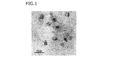
- FIG. 1 is an example of a transmission electron microscope (TEM) image of ferrite in pearlite in a thin film sample.
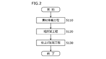
- FIG. 2 is a flow chart showing the manufacturing process of the steel material of this embodiment.
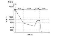
- FIG. 3 is a diagram showing an example of the temperature history of the steel material in the finish rolling process in FIG.
- FIG. 4 is a diagram showing a continuous cooling transformation curve (CCT curve) in the cooling process of the steel material of this embodiment in FIG.
- FIG. 5 is a flow chart showing the steps of manufacturing a spring using the steel material of this embodiment.
- TEM transmission electron microscope
- the inventors first studied the chemical composition and microstructure of steel materials suitable for springs such as damper springs and valve springs.
- a chemical composition that provides the fatigue strength of a spring manufactured using steel as a raw material is suitable as a steel material for spring applications.
- a structure that allows the steel material to be shaved in the shaving process (peeling) during the spring manufacturing process is suitable as the steel material for spring applications.
- the chemical composition of the steel material is, in mass%, C: 0.50 to 0.80%, Si: 1.20 to 2.90%, Mn: 0.25 to 1.00%, Cr: 0 .40-1.90%, V: 0.05-0.60%, P: 0.020% or less, S: 0.020% or less, N: 0.0100% or less, Mo: 0-0.50 %, Nb: 0-0.050%, W: 0-0.60%, Ni: 0-0.50%, Co: 0-0.30%, B: 0-0.0050%, Cu: 0 ⁇ 0.050%, Al: 0 to 0.0050%, and Ti: 0 to 0.050%, the balance being Fe and impurities, if the pearlite area ratio in the microstructure is 90% or more , thought that the steel would be suitable for spring applications.
- the present inventors investigated means for suppressing the surface roughness of the steel material after shaving in the steel material having the chemical composition and microstructure described above. As a result, the following findings were obtained.
- the shaving process is, as described above, a process of stripping (cutting) the entire surface of the steel material (wire material) using a shaving die.
- the shaving treatment since the entire surface of the steel material is peeled off, scales and decarburized layers on the surface of the steel material can be removed, and defects such as rolling flaws can be removed. As a result, the surface of the steel material becomes smooth after shaving.
- shaving-induced defects such as burrs, rips, or cracks occur on the steel material surface after the shaving process.
- Shaving-induced flaws reduce the smoothness of the surface of the steel material, forming a rough surface on the surface of the steel material. Therefore, the present inventors investigated the cutting mechanism of the steel material surface during the shaving process. As a result, the following findings were obtained.
- the surface of the steel material is cut with a shaving die.
- the cut steel portion is separated from the steel surface as chips.
- part of the chips may remain on the surface of the steel material during the shaving process, or the steel material portion near the root of the chips may The steel may be ripped off, or cracks may occur on the surface of the steel material near the root of the chips. Part of the remaining chips and rips and cracks generated at the base of the chips become flaws caused by shaving, forming rough surface on the surface of the steel material.
- the present inventors considered that if chips generated by cutting with a shaving die are easily separated from the surface of the steel material during the shaving process, the chips will be cut short. If the chips are cut short, the short chips are easily separated from the steel material surface. Therefore, it is possible to prevent a part of the chips from remaining on the steel material surface, the steel material portion near the root of the chips from being plucked, and the steel material surface near the root of the chips from cracking. As a result, the occurrence of scratches caused by shaving is suppressed, the roughening of the surface of the steel material is suppressed, and the smoothness of the surface of the steel material can be secured.
- the present inventors further investigated means for cutting chips in the shaving process into short pieces in the steel material having the above-described chemical composition and microstructure.
- MnS which is an inclusion in steel
- MnS which is an inclusion
- MnS can reduce fatigue characteristics. Therefore, the present inventors considered that it is not appropriate to utilize MnS in the steel material to suppress roughening of the surface of the steel material after shaving. Therefore, the present inventors have considered using means other than MnS to suppress roughening of the surface of the steel material after shaving.
- the inventors paid attention to the microstructure of the steel material that is the material of the spring.
- the microstructure of the steel used as the material for the spring is a pearlite-based structure with a pearlite area ratio of 90% or more.
- Pearlite is composed of ferrite and cementite. Since ferrite is softer than cementite, it is less likely to break than cementite during shaving. Therefore, the inventors of the present invention focused on ferrite in the pearlite structure and studied means for facilitating the division of ferrite.
- the present inventors considered using precipitates that precipitate in ferrite instead of inclusions such as MnS in order to facilitate the division of ferrite during shaving treatment. Then, they thought that if a large amount of nano-sized fine V-based precipitates were intentionally formed in ferrite, the ferrite would be easily split during shaving treatment.
- the fine V-based precipitates are precipitates containing V and having a maximum diameter of 2 to 20 nm in the field of observation with a TEM (transmission electron microscope) described later.
- Precipitates containing V are, for example, V carbides, V carbonitrides, and the like.
- V-based precipitates can be generated in ferrite by interphase precipitation.
- the V-based precipitates are much finer than those of MnS. Specifically, the size of MnS is about 1 ⁇ m even at the smallest size, whereas V-based precipitates can be formed with a size of about 2 to 20 nm. If the size of the precipitates is small, they are unlikely to become starting points for fatigue fracture. Therefore, the V-based precipitates are less likely to reduce the fatigue strength of the spring. On the other hand, if a large number of V-based precipitates are formed in the ferrite, the ferrite tends to be cut into short pieces by the V-based precipitates during the peeling treatment. As a result, it is considered that shaving-induced flaws such as remaining chips, plucking, and cracking are less likely to occur.
- V-based precipitates can also suppress wear of shaving dies.
- the hardness of V-based precipitates is high.
- some of the V-based precipitates contained in the chips adhere to the cutting edge of the shaving die.
- the deposited V-based precipitates enhance the wear resistance of the cutting edge of the shaving die. If the wear resistance of the cutting edge of the shaving dies is improved, the cutting power (shaving power) of the shaving dies can be maintained. Therefore, it is possible to maintain the ease of cutting chips from the surface of the steel material.
- the present inventors conducted further detailed studies on the number density of V-based precipitates in the steel that can sufficiently suppress the roughening of the steel during shaving.
- the inventors of the present invention have found that in a steel material in which the content of each element in the chemical composition is within the above range and the pearlite area ratio in the microstructure is 90% or more, the maximum diameter of ferrite in the pearlite is 2 It has been found that if the number density of V-based precipitates of up to 20 nm is 3,000 to 80,000/ ⁇ m 3 , roughening of the steel material after shaving treatment can be sufficiently suppressed.
- the steel material of this embodiment has been completed based on the above technical concept.
- the steel material according to this embodiment has the following configuration.
- [1] is steel, The chemical composition, in mass %, C: 0.50 to 0.80%, Si: 1.20 to 2.90%, Mn: 0.25-1.00%, Cr: 0.40 to 1.90%, V: 0.05 to 0.60%, P: 0.020% or less, S: 0.020% or less, N: 0.0100% or less, Mo: 0-0.50%, Nb: 0 to 0.050%, W: 0 to 0.60%, Ni: 0 to 0.50%, Co: 0-0.30%, B: 0 to 0.0050%, Cu: 0-0.050%, Al: 0 to 0.0050%, and Ti: 0 to 0.050%, containing The balance consists of Fe and impurities, In the microstructure of the steel material, the pearlite area ratio is 90% or more, In the ferrite in the pearlite, The number density of V-based precipitates with a maximum diameter of 2 to 20 nm is 3000 to 80000 / ⁇ m 3 , steel.
- C 0.50-0.80% Carbon (C) increases the fatigue strength of springs made of steel. If the C content is less than 0.50%, the above effect cannot be sufficiently obtained even if the content of other elements is within the range of the present embodiment. On the other hand, if the C content exceeds 0.80%, coarse cementite is formed even if the content of other elements is within the range of the present embodiment. Coarse cementite reduces the ductility of the steel material. Coarse cementite further reduces the fatigue strength of springs made from steel. Therefore, the C content is 0.50-0.80%.
- the lower limit of the C content is preferably 0.51%, more preferably 0.52%, still more preferably 0.53%, still more preferably 0.54%.
- the upper limit of the C content is preferably 0.79%, more preferably 0.78%, still more preferably 0.76%, still more preferably 0.74%, still more preferably 0.72 %, more preferably 0.70%, more preferably 0.68%.
- Si 1.20-2.90%
- Silicon (Si) increases the fatigue strength of springs made of steel. Si also deoxidizes the steel. Si also increases the temper softening resistance of the steel. Therefore, even after thermal refining (quenching and tempering) is performed in the manufacturing process of the spring, the fatigue strength of the spring is maintained high. If the Si content is less than 1.20%, the above effect cannot be sufficiently obtained even if the content of other elements is within the range of the present embodiment. On the other hand, if the Si content exceeds 2.90%, the ductility of the steel material, which is the raw material of the spring, is excessively lowered even if the content of other elements is within the range of the present embodiment. Furthermore, the fatigue strength of springs made of steel is reduced.
- the Si content is 1.20-2.90%.
- the lower limit of the Si content is preferably 1.25%, more preferably 1.30%, still more preferably 1.35%, still more preferably 1.40%, still more preferably 1.45 %, more preferably 1.50%, more preferably 1.55%, still more preferably 1.60%.
- the preferred upper limit of the Si content is 2.85%, more preferably 2.80%, still more preferably 2.75%, still more preferably 2.70%, still more preferably 2.65 %, more preferably 2.60%.
- Mn 0.25-1.00%
- Manganese (Mn) enhances the hardenability of steel and enhances the fatigue strength of springs made from steel. If the Mn content is less than 0.25%, the above effect cannot be sufficiently obtained even if the content of other elements is within the range of the present embodiment. On the other hand, if the Mn content exceeds 1.00%, even if the content of other elements is within the range of the present embodiment, the strength of the steel material becomes excessively high during the spring manufacturing process, and the steel material is processed. diminished sexuality. Therefore, the Mn content is 0.25-1.00%.
- the preferred lower limit of the Mn content is 0.28%, more preferably 0.30%, still more preferably 0.35%, still more preferably 0.40%, still more preferably 0.45 %, more preferably 0.50%, more preferably 0.55%.
- the preferred upper limit of the Mn content is 0.95%, more preferably 0.90%, still more preferably 0.85%, still more preferably 0.80%, still more preferably 0.75 %.
- Chromium (Cr) enhances the hardenability of steel and enhances the fatigue strength of springs made from steel. If the Cr content is less than 0.40%, the above effect cannot be sufficiently obtained even if the content of other elements is within the range of the present embodiment. On the other hand, if the Cr content exceeds 1.90%, coarse Cr carbides are excessively formed even if the content of other elements is within the range of the present embodiment. Coarse Cr carbides reduce the fatigue strength of the spring. Therefore, the Cr content is 0.40-1.90%.
- a preferable lower limit of the Cr content is 0.45%, more preferably 0.50%, still more preferably 0.55%, still more preferably 0.60%, still more preferably 0.65 %, more preferably 0.70%, more preferably 0.75%, still more preferably 0.80%.
- the upper limit of the Cr content is preferably 1.85%, more preferably 1.80%, still more preferably 1.75%, still more preferably 1.70%, still more preferably 1.65 %, more preferably 1.60%.
- V 0.05-0.60% Vanadium (V) combines with C and/or N to form V-based precipitates with a maximum diameter of 2 to 20 nm in ferrite of pearlite.
- the V-based precipitates facilitate splitting of ferrite during shaving. Therefore, the V-based precipitates make it easier to divide the chips into short pieces during the shaving process. As a result, roughening of the surface of the steel material after shaving is suppressed, and the smoothness of the surface of the steel material is enhanced. If the V content is less than 0.05%, the above effect cannot be sufficiently obtained even if the content of other elements is within the range of the present embodiment.
- the V content is 0.05-0.60%.
- the lower limit of the V content is preferably 0.06%, more preferably 0.07%, still more preferably 0.08%, still more preferably 0.10%, still more preferably 0.15 %, more preferably 0.17%, more preferably 0.18%, still more preferably 0.20%.
- the upper limit of the V content is preferably 0.58%, more preferably 0.57%, still more preferably 0.55%, still more preferably 0.53%, still more preferably 0.50 %, more preferably 0.45%, more preferably 0.40%, still more preferably 0.35%, still more preferably 0.30%.
- Phosphorus (P) is an impurity. P segregates at grain boundaries and lowers the fatigue strength of springs made of steel. Therefore, the P content is 0.020% or less.
- the upper limit of the P content is preferably 0.018%, more preferably 0.016%, still more preferably 0.014%, still more preferably 0.012%, still more preferably 0.010 %. It is preferable that the P content is as low as possible, and the most preferable P content is 0%. However, excessive reduction of the P content raises production costs. Therefore, considering normal industrial production, the preferable lower limit of the P content is more than 0%, more preferably 0.001%, more preferably 0.002%, and still more preferably 0.003%. %.
- S 0.020% or less Sulfur (S) is an impurity. Like P, S segregates at grain boundaries or combines with Mn to form MnS, thereby lowering the fatigue strength of a spring manufactured using steel. Therefore, the S content is 0.020% or less.
- the preferred upper limit of the S content is 0.018%, more preferably 0.016%, still more preferably 0.014%, still more preferably 0.012%, still more preferably 0.010 %.
- the S content is preferably as low as possible, and the S content is most preferably 0%. However, excessive reduction of the S content raises manufacturing costs. Therefore, considering normal industrial production, the preferable lower limit of the S content is more than 0%, more preferably 0.001%, still more preferably 0.002%, still more preferably 0.003%. %.
- N 0.0100% or less Nitrogen (N) is an impurity. N combines with Al or Ti to form AlN or TiN, which lowers the fatigue strength of springs made of steel. Therefore, the N content is 0.0100% or less.
- the upper limit of the N content is preferably 0.0095%, more preferably 0.0090%, still more preferably 0.0085%, still more preferably 0.0080%, still more preferably 0.0075 %, more preferably 0.0070, more preferably 0.0065%, still more preferably 0.0060%.
- the N content is preferably as low as possible, and the N content is most preferably 0%. However, excessive reduction of the N content raises manufacturing costs. Therefore, the preferred lower limit of the N content is more than 0%, more preferably 0.0001%, still more preferably 0.0003%, still more preferably 0.0005%, still more preferably 0.0005%. 0007%, more preferably 0.0010%.
- the remainder of the chemical composition of the steel material according to this embodiment consists of Fe and impurities.
- the impurities are those that are mixed from ore, scrap, or the manufacturing environment as raw materials when the steel material is industrially manufactured, and are within a range that does not adversely affect the steel material of the present embodiment. means acceptable.
- the chemical composition of the steel material according to the present embodiment may further contain one or more selected from the group consisting of Mo, Nb, W, Ni, Co and B instead of part of Fe. These elements are arbitrary elements, and all increase the fatigue strength of the spring manufactured using the steel material of this embodiment.
- Mo 0-0.50% Molybdenum (Mo) is an optional element and may not be contained. That is, the Mo content may be 0%. When contained, that is, when the Mo content is more than 0%, Mo enhances the hardenability of the steel material and enhances the fatigue strength of the spring manufactured using the steel material. Mo also increases the temper softening resistance of the steel. Therefore, the fatigue strength of the spring is maintained high even after the thermal refining process is performed in the manufacturing process of the spring. If even a little Mo is contained, the above effect can be obtained to some extent.
- the Mo content is 0-0.50%, and when Mo is included, the Mo content is greater than 0-0.50%.
- a preferable lower limit of the Mo content is 0.01%, more preferably 0.05%, and still more preferably 0.10%.
- a preferred upper limit of the Mo content is 0.45%, more preferably 0.40%, still more preferably 0.35%, still more preferably 0.30%.
- Niobium (Nb) is an optional element and may not be contained. That is, the Nb content may be 0%. When contained, that is, when the Nb content exceeds 0%, Nb combines with C and/or N to form carbides or carbonitrides (hereinafter referred to as Nb carbonitrides, etc.). Nb carbonitride or the like refines austenite grains. Therefore, the fatigue strength of the spring manufactured using steel is increased. If even a small amount of Nb is contained, the above effect can be obtained to some extent. However, if the Nb content exceeds 0.050%, coarse Nb carbonitrides and the like are formed even if the content of other elements is within the range of the present embodiment.
- the Nb content is 0-0.050%, and when Nb is included, the Nb content is greater than 0%-0.050%.
- a preferable lower limit of the Nb content is 0.001%, more preferably 0.005%, and still more preferably 0.010%.
- the preferred upper limit of the Nb content is 0.045%, more preferably 0.040%, still more preferably 0.035%, still more preferably 0.030%, still more preferably 0.025 %.
- W 0-0.60% Tungsten (W) is an optional element and may not be contained. That is, the W content may be 0%. When contained, that is, when the W content is more than 0%, W enhances the hardenability of the steel material and enhances the fatigue strength of the spring manufactured using the steel material. W also increases the temper softening resistance of the steel. Therefore, the fatigue strength of the spring manufactured using the steel material is maintained high even after the thermal refining process is performed in the manufacturing process of the spring. If even a small amount of W is contained, the above effect can be obtained to some extent.
- the W content is 0-0.60%, and when W is included, the W content is greater than 0-0.60%.
- a preferable lower limit of the W content is 0.01%, more preferably 0.05%, and still more preferably 0.10%.
- the preferred upper limit of the W content is 0.55%, more preferably 0.50%, still more preferably 0.45%, still more preferably 0.40%, still more preferably 0.35 %, more preferably 0.30%.
- Nickel (Ni) is an optional element and may not be contained. That is, the Ni content may be 0%. When contained, that is, when the Ni content is more than 0%, Ni enhances the hardenability of the steel material and enhances the fatigue strength of the spring manufactured using the steel material. If Ni is contained even in a small amount, the above effect can be obtained to some extent. However, if the Ni content exceeds 0.50%, the strength of the steel material becomes excessively high and the workability of the steel material deteriorates even if the other element contents are within the ranges of the present embodiment. Therefore, the Ni content is 0 to 0.50%, and when Ni is included, the Ni content is greater than 0 to 0.50%.
- the preferred lower limit of the Ni content is 0.01%, more preferably 0.02%, still more preferably 0.03%, still more preferably 0.05%, still more preferably 0.10 %.
- a preferable upper limit of the Ni content is 0.45%, more preferably 0.40%, and still more preferably 0.35%.
- Co is an optional element and may not be contained. That is, the Co content may be 0%. When included, that is, when the Co content is greater than 0%, Co increases the temper softening resistance of the steel. Therefore, the fatigue strength of the spring manufactured using the steel material is maintained high even after the thermal refining process is performed in the manufacturing process of the spring. If even a small amount of Co is contained, the above effect can be obtained to some extent. However, if the Co content exceeds 0.30%, the strength of the steel material becomes excessively high and the workability of the steel material deteriorates even if the contents of other elements are within the ranges of the present embodiment.
- the Co content is 0-0.30%, and when Co is included, the Co content is greater than 0-0.30%.
- the lower limit of the Co content is preferably 0.01%, more preferably 0.05%, still more preferably 0.10%.
- the upper limit of the Co content is preferably 0.28%, more preferably 0.26%, still more preferably 0.24%, still more preferably 0.22%, still more preferably 0.20 %.
- B 0 to 0.0050%
- Boron (B) is an optional element and may not be contained. That is, the B content may be 0%. When contained, that is, when the B content is more than 0%, B enhances the hardenability of the steel material and enhances the fatigue strength of the spring manufactured using the steel material. If even a small amount of B is contained, the above effect can be obtained to some extent. However, if the B content exceeds 0.0050%, the strength of the steel material becomes excessively high and the workability of the steel material deteriorates even if the contents of other elements are within the ranges of the present embodiment. Therefore, the B content is 0 to 0.0050%, and when B is included, the B content is greater than 0 to 0.0050%.
- the preferred lower limit of the B content is 0.0001%, more preferably 0.0005%, still more preferably 0.0010%, still more preferably 0.0015%, still more preferably 0.0020 %.
- the preferred upper limit of the B content is 0.0049%, more preferably 0.0048%, still more preferably 0.0047%, still more preferably 0.0045%, still more preferably 0.0043 %, more preferably 0.0040%.
- the chemical composition of the steel material according to the present embodiment may further contain one or more impurities selected from the group consisting of Cu, Al and Ti instead of part of Fe. If the contents of these elements are within the ranges described below, the above-described effects of the steel material according to the present embodiment can be sufficiently obtained.
- Cu is an impurity and is preferably not contained. That is, the Cu content may be 0%. If the Cu content exceeds 0.050%, the workability of the steel is remarkably lowered even if the content of other elements is within the range of the present embodiment. Therefore, the Cu content is 0-0.050%.
- a preferred upper limit of the Cu content is 0.045%, more preferably 0.040%, still more preferably 0.038%, still more preferably 0.036%. As described above, the Cu content is preferably as low as possible. However, excessive reduction of Cu content raises manufacturing costs. Therefore, the preferred lower limit of the Cu content is over 0%, more preferably 0.001%, still more preferably 0.002%.
- Al is an impurity and is preferably not contained. That is, the Al content may be 0%. Al forms coarse non-metallic inclusions and lowers the fatigue strength of springs made of steel. If the Al content exceeds 0.0050%, the fatigue strength of the spring is remarkably lowered even if the content of other elements is within the range of the present embodiment. Therefore, the Al content is 0-0.0050%.
- the preferred upper limit of the Al content is 0.0045%, more preferably 0.0040%, still more preferably 0.0035%, still more preferably 0.0032%, still more preferably 0.0030 %. As described above, the lower the Al content is, the better. However, excessive reduction of Al content raises production costs. Therefore, the preferred lower limit of the Al content is over 0%, more preferably 0.0001%, still more preferably 0.0005%.
- Titanium (Ti) is an impurity and is preferably not contained. That is, the Ti content may be 0%. Ti forms coarse TiN. TiN tends to be a starting point of fracture. Therefore, TiN lowers the fatigue strength of springs made of steel. If the Ti content exceeds 0.050%, the fatigue strength of the spring is significantly lowered even if the content of other elements is within the range of the present embodiment. Therefore, the Ti content is 0-0.050%.
- the upper limit of the Ti content is preferably 0.045%, more preferably 0.040%, still more preferably 0.035%, still more preferably 0.032%, still more preferably 0.030 %. As described above, the Ti content is preferably as low as possible. However, excessive reduction of Ti content raises production costs. Therefore, the lower limit of the Ti content is preferably over 0%, more preferably 0.001%, still more preferably 0.003%, still more preferably 0.005%.
- the microstructure of the steel material of this embodiment is a pearlite-based structure.
- the microstructure is a pearlite-based structure
- the microstructure has a pearlite area ratio of 90% or more.
- Phases other than pearlite are, for example, precipitates, inclusions, ferrite, and hard phases (martensite and/or bainite). The area ratios of precipitates and inclusions are so small that they can be ignored compared to other phases.
- the pearlite area ratio can be obtained by the following method.
- the observation surface is the cross section (surface) cut in the direction perpendicular to the longitudinal direction of the steel material, that is, the wire diameter direction of the steel material. Polish the viewing surface to a mirror finish.
- the mirror-polished viewing surface is etched with 5% picric acid alcohol (picral etchant).
- picral etchant 5% picric acid alcohol
- the observation field is defined as the depth position of 1/4 of the diameter in the radial direction from the surface of the steel material (periphery of the observation surface).
- Ten observation fields are observed using a scanning electron microscope (SEM) at a magnification of 2000 to generate photographic images of the ten observation fields.
- the size of each field of view is 40 ⁇ m ⁇ 60 ⁇ m.
- each phase such as pearlite, ferrite, hard phase, precipitates, and inclusions differs in contrast and phase morphology. Therefore, perlite is identified based on contrast and morphology. Pearlite is in the form of alternating layers of cementite and ferrite. Therefore, one skilled in the art can readily distinguish perlite from other phases by contrast and morphology.
- the total perlite area ( ⁇ m 2 ) in each observation field is determined.
- the ratio of the total area of pearlite in all observation fields to the total area (24000 ⁇ m 2 ) of all observation fields is defined as pearlite area ratio (%).
- the pearlite area ratio is a value (that is, an integer) obtained by rounding off the value to the first decimal place.
- the pearlite area ratio in the microstructure of the steel material of this embodiment is 90% or more. Therefore, compared with steel materials mainly composed of hard phases (martensite and/or bainite), the surface of steel materials can be easily ground in shaving treatment, and cold workability is also high. As described above, in the spring manufacturing process, the steel material is subjected to a shaving process and then to a wire drawing process. Therefore, the steel material of this embodiment is suitable for manufacturing springs. In addition, in the steel material of this embodiment, the preferable lower limit of the pearlite area ratio is 91%, and more preferably 92%.
- the number density of V-based precipitates having a maximum diameter of 2 to 20 nm in ferrite in pearlite is 3000 to 80000/ ⁇ m 3 .
- the number density of V-based precipitates means the number of V-based precipitates per unit area (1 ⁇ m 3 in this specification).
- V-based precipitates are precipitates containing V.
- the V-based precipitates may contain Cr as well as V.
- V-based precipitates are, for example, V-carbides and V-carbonitrides.
- the V-based precipitates may be composite precipitates containing V carbide and elements other than V, Cr, and C, or V carbonitrides and elements other than V, Cr, C, and N. It may be a composite precipitate containing and.
- the V-based precipitates are extremely fine compared to Fe carbides such as cementite. Therefore, it can be easily distinguished from Fe carbides such as cementite, and the V-based precipitates can be identified.
- V or V and Cr are detected by elemental analysis with an energy dispersive X-ray spectroscopy (EDS), and a nanobeam diffraction pattern ( Analysis using Nano Beam Electron Diffraction (NBD) revealed that the crystal structure was cubic, and the lattice constants a, b, and c were all 0.4167 nm ⁇ 5% (ICDD (International Center for Diffraction Data) No. 065-8822).
- EDS energy dispersive X-ray spectroscopy
- NBD Nano Beam Electron Diffraction
- a large number of fine V-based precipitates with a maximum diameter of 2 to 20 nm are precipitated in ferrite in pearlite.
- these fine V-based precipitates facilitate the division of ferrite in chips generated from the surface of the steel material by shaving treatment. As a result, chips are easily cut short. As a result, it is possible to prevent a part of the chips from remaining on the steel material surface, the steel material portion near the root of the chips from being plucked, and the steel material surface near the root of the chips from cracking. That is, the occurrence of shaving-induced flaws is suppressed, and the roughening of the surface of the steel material is suppressed.
- the number density of V-based precipitates having a maximum diameter of 2 to 20 nm in ferrite in pearlite is less than 3000/ ⁇ m 3 , the number density of V-based precipitates is insufficient. In this case, roughening of the surface of the steel material after shaving cannot be sufficiently suppressed. If the number density of V-based precipitates having a maximum diameter of 2 to 20 nm in ferrite in pearlite is 3000/ ⁇ m 3 or more, the number density of V-based precipitates in ferrite in pearlite is sufficiently high.
- the number density of V-based precipitates having a maximum diameter of 2 to 20 nm in ferrite in pearlite is 3000 It is 3 or more pieces/ ⁇ m.
- a preferable lower limit of the number density of V-based precipitates having a maximum diameter of 2 to 20 nm in ferrite in pearlite is 3500/ ⁇ m3 , more preferably 4000/ ⁇ m3 , and still more preferably 4500/ ⁇ m3 . , more preferably 5000/ ⁇ m3 , more preferably 5500/ ⁇ m3 , still more preferably 6000/ ⁇ m3 , still more preferably 6500/ ⁇ m3 , still more preferably 7000 / ⁇ m 3 , more preferably 8,000/ ⁇ m 3 , more preferably 9,000/ ⁇ m 3 , still more preferably 10,000/ ⁇ m 3 , still more preferably 15,000/ ⁇ m 3 .
- the upper limit of the number density of V-based precipitates having a maximum diameter of 2 to 20 nm is not particularly limited. However, when the content of each element in the chemical composition of the steel is within the range of this embodiment, the upper limit of the number density of V-based precipitates with a maximum diameter of 2 to 20 nm in ferrite in pearlite is 80000/ ⁇ m 3 .
- the upper limit of the number density of V-based precipitates having a maximum diameter of 2 to 20 nm in ferrite in pearlite is preferably 75,000/ ⁇ m 3 , more preferably 72,000/ ⁇ m 3 .
- the number density (pieces/ ⁇ m 3 ) of V-based precipitates having a maximum diameter of 2 to 20 nm in ferrite in pearlite can be obtained by the following method.
- the steel material (wire material) according to the present embodiment is cut in the wire diameter direction.
- a disc having a cross section in the direction of the wire diameter and a thickness of 0.5 mm in the direction of the central axis of the steel material is sampled.
- the disk is ground and polished from both sides to a thickness of 60 ⁇ m.
- a sample of 3 mm diameter is then taken from the disc.
- the sample is immersed in a 10% perchloric acid-glacial acetic acid solution and subjected to electropolishing to prepare a thin film sample with a thickness of 100 nm.
- perlite can be easily distinguished from other phases by contrast and morphology.
- pearlite can be identified as a lamellar structure that is a striped pattern of white regions and black regions.
- the white regions are ferrite and the black regions are cementite. Therefore, the contrast allows the ferrite in the pearlite to be easily distinguished and identified from the cementite in the pearlite. Therefore, based on the contrast, five observation fields are selected in the ferrite in the pearlite.
- precipitates can be identified by contrast. Therefore, among the specified plurality of precipitates, precipitates having a maximum diameter of 2 to 20 nm are specified.
- the maximum diameter is the maximum line segment length when two arbitrary points on the interface between the precipitate and the matrix are selected and the entire line segment connecting the two points is included in the precipitate.
- precipitates with a maximum diameter of 2 to 20 nm are V-based precipitates. Therefore, precipitates with a maximum diameter of 2 to 20 nm are identified as V-based precipitates. It can be confirmed by using EDS and NBD that the precipitates with a maximum diameter of 2 to 20 nm are V-based precipitates. Specifically, each precipitate having a maximum diameter of 2 to 20 nm is irradiated with a beam to detect characteristic X-rays, and an elemental analysis in the precipitate is performed. Furthermore, a nanobeam diffraction pattern (NBD) is obtained by nanobeam diffraction (microelectron diffraction) for each precipitate with a maximum diameter of 2 to 20 nm.
- NBD nanobeam diffraction pattern
- the obtained nanobeam diffraction pattern is analyzed to determine the crystal structure and lattice constant of the precipitate. If V or V and Cr are detected by EDS, and further, as a result of analyzing NBD, the crystal structure is cubic and lattice constants a, b, and c are all 0.4167 nm ⁇ 5%, The precipitates are V-based precipitates.
- Fig. 1 is an example of a TEM image of ferrite in pearlite of a thin film sample.
- reference numeral 10 denotes V-based precipitates.
- the total number of V-based precipitates with a maximum diameter of 2 to 20 nm is determined in five observation fields. Based on the obtained total number of V-based precipitates and the total volume of the five observation fields, the number density (number/ ⁇ m 3 ) of V-based precipitates with a maximum diameter of 2 to 20 nm is obtained.
- the steel material of the present embodiment has a chemical composition in which the content of each element is within the range of the present embodiment, and the pearlite area ratio in the microstructure is 90% or more. Furthermore, in ferrite in pearlite, the number density of V-based precipitates having a maximum diameter of 2 to 20 nm is 3000 to 80000/ ⁇ m 3 . Therefore, the steel material of the present embodiment can sufficiently suppress the occurrence of shaving-induced flaws such as burrs, rips, and cracks on the surface of the steel material after the shaving process in the shaving process during the manufacturing process of the spring. As a result, roughening of the steel material surface after shaving treatment can be sufficiently suppressed, and the smoothness of the steel material surface can be sufficiently improved.
- FIG. 2 is a flow chart showing an example of the manufacturing process of the steel material of this embodiment.
- the steel manufacturing method of the present embodiment includes a material preparation step (S110), a rough rolling step (S120), and a finish rolling step (S130). Each step will be described in detail below.
- molten steel having a chemical composition in which the content of each element is within the range of the present embodiment is produced by a well-known refining method.
- a raw material (bloom or ingot) is manufactured using the manufactured molten steel. Specifically, the bloom is produced by a continuous casting method using molten steel. Alternatively, an ingot is produced by an ingot casting method using molten steel.
- the raw material is hot rolled to produce a billet.
- the material is first heated in the rough rolling step (S120).
- a heating furnace or soaking furnace is used to heat the material.
- the material is heated to 1200-1300° C. in a heating furnace or soaking furnace.
- the material is held at a furnace temperature of 1200-1300° C. for 1.5-50.0 hours.
- the material after heating is extracted from the heating furnace or the soaking furnace, and hot rolling is performed.
- a blooming mill is used for hot rolling in the rough rolling step (S120.
- the material is bloomed by a blooming mill to produce a billet.
- a continuous rolling mill When a continuous rolling mill is installed downstream of the blooming mill, the billet after blooming is further hot-rolled using the continuous rolling mill to produce a smaller billet.
- rolling stands having a pair of horizontal rolls (horizontal stands) and rolling stands having a pair of vertical rolls (vertical stands) are alternately arranged in a row.
- the raw material (bloom or ingot) is manufactured into a billet.
- the heating temperature in the heating furnace in the finish rolling process shall be 1050° C. or higher.
- the holding time at the heating temperature of 1050° C. or higher is, for example, 0.5 to 5.0 hours.
- V-based precipitates may be generated in the billet due to cooling after hot rolling. If finish rolling is performed on a billet in which V-based precipitates remain in the billet, coarse V-based precipitates are excessively generated in the ferrite in the pearlite of the steel material after the finish rolling process. As a result, the number density of V-based precipitates having a maximum diameter of 2 to 20 nm in ferrite in pearlite is less than 3000/ ⁇ m 3 .
- the heating temperature in the finish rolling step (S130) is 1050° C. or higher, the V-based precipitates that may remain in the billet after the rough rolling step (S120) can be sufficiently dissolved. . Therefore, on the premise that other manufacturing conditions are satisfied, the formation of coarse V-based precipitates with a maximum diameter exceeding 20 nm is suppressed, and the maximum diameter of ferrite in the pearlite of the steel material after the finish rolling process is 2 to 20 nm.
- the number density of V-based precipitates is 3000 pieces/ ⁇ m 3 or more.
- the heated billet is subjected to hot rolling (finish rolling) using a row of finishing rolling mills to produce a wire rod, which is a steel material.
- finish rolling hot rolling
- the outer diameter of the wire is not particularly limited, the outer diameter of the wire is, for example, 5 to 10 mm.
- the outer diameter of the steel material (wire material) is determined based on the wire diameter of the spring, which is the final product.
- a finishing mill train includes a plurality of rolling stands arranged in a row from upstream to downstream. Each stand includes multiple rolls arranged around the pass line. The rolling rolls of each stand are formed with grooves. A billet is passed through a groove formed by a plurality of rolls of each stand and subjected to hot rolling to gradually reduce the cross section of the billet to produce a steel material (wire material).
- a group of rolling stands arranged continuously from the most upstream rolling stand is called a "row of roughing mills.”
- a group of rolling stands arranged downstream of the row of roughing mills and arranged in succession is called an "intermediate rolling mill row”.
- a group of rolling stands arranged downstream of the intermediate rolling mill train and arranged one or in succession is referred to as a "last rolling mill train”.
- the finishing rolling mill line is divided into three rolling stand groups from upstream to downstream: a roughing rolling mill line, an intermediate rolling mill line, and a final rolling mill line.
- the number of rolling stands in the roughing mill train, the number of rolling stands in the intermediate rolling mill train, and the number of rolling stands in the final rolling mill train are not particularly limited.
- the row of finishing rolling mills is divided into three rolling stand groups (a row of rough rolling mills, a row of intermediate rolling mills, and a row of final rolling mills) for convenience.
- Water cooling devices for cooling the steel material are arranged between several rolling stands of the row of rough rolling mills, the row of intermediate rolling mills, and the row of final rolling mills.
- the water cooling device performs water cooling on the steel material that exits the preceding rolling stand and enters the subsequent rolling stand, which is the next rolling stand, that is, the steel material portion between the preceding rolling stand and the subsequent rolling stand. to lower the steel temperature.
- FIG. 3 is a schematic diagram of the temperature history of steel during finish rolling.
- section S131 is the temperature history of the steel material during the time until the steel material extracted from the heating furnace reaches the top rolling stand of the roughing mill line of the finishing mill line.
- Section S132 is the temperature history of the steel material in the row of roughing mills.
- Section S133 is the temperature history of the steel material in the intermediate rolling mill train.
- Section S134 is the temperature history of the steel material in the final rolling mill train.
- Interval S135 is the temperature history of the steel material after leaving the rolling stand at the end of the last row of rolling mills.
- the steel material of the present embodiment is manufactured through the temperature history of S131 to S135 shown in FIG. Each section S131 to S135 will be described below.
- the steel material temperature rises in the steel material in which processing heat is generated. Therefore, in normal finish rolling, the temperature of the steel material rises again during rolling in the rolling stands downstream of the row of roughing mills or during rolling in the row of intermediate rolling mills. The steel material temperature continues to rise even in the final rolling mill train.
- the temperature history of the steel material during the finish rolling is changed. Adjust as follows.
- the period during which the billet surface temperature is continuously maintained at 950 to 850° C. during finish rolling (referred to as specific temperature residence time) is set to 5 to 100 seconds.
- the specific temperature residence time affects the number density of V-based precipitates with a maximum diameter of 2 to 20 nm in ferrite in pearlite of the steel material after the finish rolling step (S130). Specifically, if the specific temperature residence time during finish rolling is 5 to 100 seconds, and on the premise that other manufacturing conditions are satisfied, the maximum diameter of ferrite in the pearlite of the steel material after the finish rolling process is 2.
- the number density of V-based precipitates up to 20 nm is 3,000 to 80,000/ ⁇ m 3 .
- V atoms or clusters of V atoms and Cr atoms are formed in the billet during finish rolling, provided other manufacturing conditions are met.
- V atoms or clusters of V atoms and Cr atoms (hereinafter also simply referred to as clusters) refer to aggregates of atoms generated in the previous stage of the generation of V-based precipitates.
- the number of V-based precipitates with a maximum diameter of 2 to 20 nm is 3,000 to 80,000/ ⁇ m 3 in the ferrite in the pearlite of the steel material.
- the temperature range (950 to 850° C.) of the specific temperature residence time described above is just below the solution temperature range (about 1000 to 1150° C.) of V-based precipitates. Therefore, in the temperature range (950 to 850 ° C.) of the specific temperature residence time, the driving force for generating the nuclei of the V-based precipitates is smaller than in the solution treatment temperature range, and the nuclei of the V-based precipitates are generated. Hateful. On the other hand, V atoms and/or Cr atoms dissolved in the billet are sufficiently diffused into the billet. As a result, clusters are formed, which is a precursor to the nucleation of V-based precipitates.
- a large number of clusters can be generated by securing a specific temperature residence time of 5 to 100 seconds.
- the number density of V-based precipitates with a maximum diameter of 2 to 20 nm in the ferrite in the pearlite of the steel material after the cooling treatment in the finish rolling step (S130) is 3000 to 80000/ ⁇ m 3 .
- the above mechanism is presumed. However, even if a different mechanism is acting, if the specific temperature residence time is 5 to 100 seconds, the maximum diameter of the ferrite in the pearlite of the steel material after the cooling treatment in the finish rolling step (S130) is 2 to 2. Examples described later prove that the number density of 20 nm V-based precipitates is 3,000 to 80,000/ ⁇ m 3 .
- the specific temperature residence time is less than 5 seconds, cluster generation will be insufficient.
- the number density of V-based precipitates with a maximum diameter of 2 to 20 nm in the ferrite in the pearlite of the steel material after the cooling treatment in the finish rolling step (S130) is less than 3000/ ⁇ m 3 .
- the specified temperature residence time exceeds 100 seconds, precipitates are generated from the clusters. Therefore, the V-based precipitates after the finish rolling process become coarse, and a large amount of V-based precipitates having a maximum diameter of more than 20 nm are generated.
- the specified temperature residence time is set to 5 to 100 seconds.
- the preferred lower limit of the specific temperature residence time is 8 seconds, more preferably 10 seconds, and even more preferably 12 seconds.
- a preferable upper limit of the specific temperature residence time is 90 seconds, more preferably 80 seconds, still more preferably 70 seconds, still more preferably 60 seconds.
- the billet during rolling in the intermediate rolling mill train is water-cooled to lower the billet surface temperature.
- the billet portion passing between the rolling stands is water-cooled by a water cooling device arranged between the rolling stands of the intermediate rolling mill row.
- the specified temperature residence time is secured for 5 to 100 seconds.
- the method for adjusting the specific temperature residence time during finish rolling is not limited to the above method.
- the surface temperature of the billet during the rolling period (S132) in the rough rolling mill train may be adjusted by water cooling or the like, or the billet surface temperature during the rolling period (S134) in the final rolling mill train may be adjusted by water cooling or the like.
- the residence time (specified temperature residence time) when the surface temperature of the billet is 950 to 850 ° C. is, as described above, a state in which the surface temperature of the billet is continuously 950 to 850 ° C. means the time of
- finish rolling temperature the surface temperature of the steel material on the delivery side of the rolling stand that rolls down last in the final row of rolling mills.
- the finish rolling temperature is less than 1000°C. If the finish rolling temperature is 1000° C. or higher, the austenite grains in the steel are coarsened. In this case, a large amount of fine V-based precipitates having a maximum diameter of less than 2 nm is generated as described later in the cooling treatment. As a result, the number density of V-based precipitates with a maximum diameter of 2 to 20 nm in the ferrite in the pearlite of the steel material after the finish rolling step (S130) is less than 3000/ ⁇ m 3 .
- the specific temperature residence time is 5 to 100 seconds, and the rolling at the end of the intermediate rolling mill row
- the finish rolling temperature in the rolling period (S134) of the final rolling mill train may be suppressed to less than 1000°C.
- the billet surface may be cooled during the rolling period (S134) of the final rolling mill train to set the finish rolling temperature to less than 1000°C.
- the preferred lower limit of the finish rolling temperature is 900°C.
- the temperature of the steel material (surface temperature of the steel material) is maintained at less than 1000°C from the elapse of the specific temperature residence time until the completion of rolling in the final rolling mill row.
- the entire rolling period in the intermediate rolling mill row is included in the specific temperature residence time.
- the specified temperature residence time is not limited to this. Part of the rolling period in the intermediate rolling mill train may correspond to the specific temperature residence time.
- the specific temperature residence time is not limited to the rolling period in the intermediate rolling mill train. In short, the period during which the temperature of the steel material is continuously 950° C. to 850° C. (specific temperature residence time) during finish rolling is 5 to 100 seconds, and the finish rolling temperature should be less than 1000° C.
- the temperature history of the steel material during finish rolling can be measured, for example, by the following method.
- Thermometers capable of measuring the surface temperature of steel materials are arranged on the entrance side or exit side of each stand of the finishing rolling mill row (rough rolling mill row, intermediate rolling mill row, and final rolling mill row). Based on the measurement results of these thermometers, the temperature history of the steel material during finish rolling can be determined.
- a cooling process is performed on the steel material immediately after completion of finish rolling in the row of finishing rolling mills (row of rough rolling mills, row of intermediate rolling mills, row of final rolling mills) (S135).
- a rapid cooling treatment RC is performed, and then a slow cooling treatment SC is performed.
- the number density of V-based precipitates with a maximum diameter of 2 to 20 nm in the ferrite in the pearlite of the steel material after the finish rolling step (S130) is set to 3000 to 80000/ ⁇ m 3 by the cooling treatment.
- the rapid cooling treatment RC and the slow cooling treatment SC will be described below.
- the steel material after finishing rolling and having a surface temperature in the temperature range of 950 to 800° C. is quenched.
- the average cooling rate at a surface temperature of 950 to 800° C. is set to more than 1.0° C. second. If the average cooling rate is 1.0° C./sec or less when the surface temperature of the steel is 950 to 800° C., the austenite grains in the steel coarsen even if other manufacturing conditions are satisfied. In this case, a large amount of V-based precipitates of less than 2 nm are produced.
- the number density of V-based precipitates with a maximum diameter of 2 to 20 nm in the ferrite in the pearlite of the steel material after the finish rolling step (S130) is less than 3000/ ⁇ m 3 .
- the steel after the finish rolling step (S130)
- the number density of V-based precipitates having a maximum diameter of 2 to 20 nm in ferrite in pearlite is 3000 to 80000/ ⁇ m 3 .
- FIG. 4 is a continuous cooling transformation curve (CCT curve) during the cooling treatment period (S135) of the steel material of this embodiment.
- CCT curve continuous cooling transformation curve
- the solid curve in the graph in FIG. 4 indicates the temperature change of the steel material with respect to the cooling time.
- a dashed curve Ps (curves Ps1 and Ps2) in FIG. 4 indicates the transformation start temperature of pearlite. If the austenite grains in the steel material are fine, the curve Ps shifts to the short time side (left side in the figure) (corresponding to the curve Ps1 in FIG. 4). If the curve Ps shifts to the short time side, the pearlite transformation starts at a temperature higher than the pearlite nose PN in the slow cooling treatment (SC) after the rapid cooling treatment (RC).
- SC slow cooling treatment
- RC rapid cooling treatment
- V-based precipitates are precipitated at the interphase boundary in the ferrite of the pearlite.
- V-based precipitates are formed on the higher temperature side than the pearlite nose PN. Therefore, the generated V precipitate grows to some extent.
- the number density of V-based precipitates having a maximum diameter of 2 to 20 nm in ferrite in pearlite can be 3000 to 80000/ ⁇ m 3 .
- the slow cooling treatment (SC) is performed immediately after the rapid cooling treatment (RC).
- the steel is cooled so that the average cooling rate is less than 2.00°C/sec when the surface temperature of the steel is less than 800°C to 600°C. If the average cooling rate is 2.00° C./second or more when the surface temperature of the steel material is less than 800° C. to 600° C., the pearlite transformation will be insufficient even if other manufacturing conditions are satisfied. As a result, the pearlite area ratio becomes less than 90%. Furthermore, since the pearlite transformation is insufficient, the interphase precipitation of V-based precipitates is also insufficient. As a result, the number density of V-based precipitates having a maximum diameter of 2 to 20 nm in ferrite in pearlite is less than 3000/ ⁇ m 3 .
- the average cooling rate is less than 2.00°C/sec when the surface temperature of the steel material is less than 800°C to 600°C
- the pearlite transformation is sufficiently accelerated.
- the pearlite area ratio becomes 90% or more.
- the number density of V-based precipitates having a maximum diameter of 2 to 20 nm in ferrite in pearlite is 3000 to 80000/ ⁇ m 3 .
- the steel material (wire rod) of the present embodiment can be manufactured by the manufacturing process described above.
- the above-mentioned manufacturing method is an example for manufacturing the steel material of this embodiment. Therefore, the content of each element in the chemical composition of the steel material is within the range of the present embodiment, the pearlite area ratio in the microstructure is 90% or more, and the maximum diameter of ferrite in the pearlite is 2 to 20 nm.
- the steel material manufacturing method of the present embodiment is not limited to the above manufacturing method.
- Springs made of steel according to the present embodiment are springs used in automobiles and general machinery, for example.
- Springs used in automobiles and general machinery are, for example, damper springs or valve springs.
- the spring made of the steel material of this embodiment is manufactured by a well-known manufacturing method.
- a spring made of the steel material of this embodiment is manufactured by the following method.
- FIG. 5 is a flow diagram showing an example of a spring manufacturing method using the steel material of this embodiment.
- the spring made of steel according to the present embodiment includes a steel wire preparation step (S200) and a spring manufacturing step (S300).
- steel wires for springs are manufactured using the steel material of this embodiment.
- the steel wire means a steel material obtained by performing wire drawing one or more times on a steel material (wire material) which is a hot-rolled material.
- the steel wire preparation step (S200) includes a shaving treatment step (S210), an annealing treatment step (S220), a wire drawing step (S230), and a refining treatment step (S240).
- the shaving treatment step (S210) In the shaving treatment step (S210), the entire surface (surrounding surface) of the steel material is peeled off (shaving treatment). It is sufficient to carry out the shaving process by a well-known method.
- a steel material wire material
- the shaving process removes surface flaws and decarburized layers of the steel material.
- Annealing treatment step (S220) In the annealing treatment step (S220), the steel material after the shaving treatment step (S210) is annealed to remove strain in the steel material generated by the shaving treatment. Annealing treatment is sufficient if it is implemented by a well-known method.
- the temperature of the annealing treatment is, for example, 300° C. or higher.
- wire drawing process (S230) In the wire drawing step (S230), wire drawing is performed on the steel material after the annealing treatment step (S220). A steel wire having a desired outer diameter is manufactured by drawing.
- the wire drawing step (S230) may be performed by a well-known method. Specifically, the steel is lubricated to form a lubricating coating, typically a phosphate coating or a metallic soap layer, on the surface of the steel. Wire drawing is performed at room temperature on the lubricated steel material.
- a wire drawing machine having a well-known configuration is used. A wire drawing machine includes a die for drawing a steel material.
- the tempering treatment step (S240) includes a quenching treatment step and a tempering treatment step.
- the steel wire is first heated above the Ac 3 transformation point.
- a high-frequency induction heating device is used. Quench the heated steel wire.
- the quenching method may be water cooling or oil cooling. The quenching process makes the microstructure of the steel wire mainly composed of martensite.
- the spring manufacturing process (S300) includes a cold coiling process (S310), a strain relief annealing process (S320), a nitriding process (S330) performed as necessary, and a shot peening process (S340). .
- the coiling device includes, for example, a plurality of conveying roller sets, a wire guide, a plurality of coil forming jigs (coiling pins), and a core bar having a semicircular cross section.
- the transport roller set includes a pair of rollers facing each other. A plurality of transport roller sets are arranged in a row. Each transport roller set sandwiches the steel material between a pair of rollers and transports the steel wire in the wire guide direction.
- a steel wire passes through a wire guide.
- a steel wire coming out of the wire guide is bent into an arc shape by a plurality of coiling pins and a core bar, and formed into a coil-shaped intermediate steel material.
- the strain relief annealing step (S320) is an essential step. In the strain relief annealing step (S320), annealing is performed to remove residual stress generated in the intermediate steel material by the cold coiling step (S310).
- the treatment temperature (annealing temperature) in the annealing treatment is, for example, 400-500.degree.
- the holding time at the annealing temperature is not particularly limited, it is, for example, 10 to 50 minutes. After the holding time has elapsed, the intermediate steel material is allowed to cool or slowly cools to room temperature.
- the nitriding step (S330) is an optional step and not an essential step. That is, the nitriding step (S330) may or may not be performed.
- nitriding treatment is performed on the intermediate steel material formed in the cold coiling step (S310) and subjected to the strain relief annealing treatment step (S320).
- the nitriding treatment referred to here also includes soft nitriding treatment.
- nitrogen is introduced into the surface layer of the intermediate steel material to form a nitrided layer (hardened layer) on the surface layer of the intermediate steel material through solid solution strengthening due to dissolved nitrogen and precipitation strengthening due to nitride formation.
- the nitriding treatment is performed at a treatment temperature (nitriding temperature) equal to or lower than the Ac1 transformation point.
- the nitriding temperature is, for example, 400-550.degree.
- the holding time at the nitriding temperature is 1.0 to 5.0 hours.
- the atmosphere in the furnace in which the nitriding treatment is performed is not particularly limited as long as it is an atmosphere in which the chemical potential of nitrogen is sufficiently high.
- the atmosphere in the furnace for nitriding treatment may be, for example, an atmosphere mixed with a carburizing gas (such as RX gas) as in soft nitriding treatment.
- the shot peening step (S340) is an essential step.
- shot peening is performed on the surface of the intermediate steel material after the nitriding step (S330). Thereby, compressive residual stress is applied to the surface layer of the spring, and the fatigue limit of the spring can be further increased.
- Shot peening may be performed by a well-known method.
- a blast material with a diameter of 0.01 to 1.5 mm is used.
- the projection material is, for example, steel shots, steel beads, etc., and well-known materials may be used.
- the compressive residual stress applied to the spring is adjusted according to the diameter of the blast material, the blast speed, the blast time, and the amount of blast to a unit area per unit time.
- a spring made from the steel material of this embodiment is manufactured by the above manufacturing process.
- the effects of the steel material of this embodiment will be described more specifically by way of examples.
- the conditions in the following examples are examples of conditions adopted for confirming the feasibility and effect of the steel material of this embodiment. Therefore, the steel material of this embodiment is not limited to this one condition example.
- a blank part in Table 1 means that the content of the corresponding element was below the detection limit.
- a bloom was produced by a continuous casting method using the above molten steel.
- a rough rolling step (S120) was performed on the bloom. Specifically, after heating the bloom, it was bloomed and then rolled by a continuous rolling mill to produce a billet with a cross section perpendicular to the longitudinal direction of 162 mm ⁇ 162 mm.
- the heating temperature in the rough rolling step (S120) was 1200 to 1250° C., and the holding time at the heating temperature was 2.0 hours.
- the finish rolling step (S130) was performed to manufacture a steel material (wire rod) with a diameter of 6.5 mm.
- the heating temperature in the finish rolling process (S130) was the temperature shown in the “heating temperature (°C)” column of the “finish rolling process” column in Table 2.
- the holding time at the heating temperature was 1.5 hours for all test numbers.
- the specific temperature residence time (continuous residence time within the range of 950 to 850 ° C.) during finish rolling is the time shown in the "Specific temperature residence time (seconds)" column in the "Finish rolling process” column of Table 2. rice field.
- the finish rolling temperature (°C) in the finish rolling process was the temperature shown in the column “finish rolling temperature (°C)” in the column “finish rolling process” in Table 2.
- the temperature of the steel material after the elapse of the specific temperature residence time was lower than the finish rolling temperature until the finish rolling was completed in any test number.
- the steel material after finish rolling was subjected to rapid cooling (RC), followed by slow cooling (SC).
- the average cooling rate in the steel material surface temperature range of 950 to 800 ° C in the rapid cooling treatment (RC) is the average cooling rate (° C. / sec).
- the average cooling rate in the steel material surface temperature range of less than 800 ° C. to 600 ° C. in the slow cooling treatment (SC) is the average shown in the column "Average cooling rate in slow cooling treatment (° C./sec)" in Table 2. was the cooling rate (°C/sec).
- the steel material was manufactured through the above manufacturing process.
- the pearlite area ratio (%) in the microstructure of the steel material of each test number was measured by the following method.
- a cross section (surface) cut in the wire diameter direction of the steel material of each test number was used as an observation surface.
- the observation surface was mirror-polished.
- the mirror-polished observation surface was etched with 5% picric acid alcohol (picral etchant).
- picral etchant 5% picric acid alcohol
- the observation field was defined as the depth position of 1/4 of the diameter in the radial direction from the surface of the steel material (periphery of the observation surface).
- Ten observation fields were observed using a scanning electron microscope (SEM) at a magnification of 2000 to generate photographic images of the ten observation fields.
- the size of each visual field was 40 ⁇ m ⁇ 60 ⁇ m.
- Perlite was identified based on contrast and phase morphology. The total perlite area ( ⁇ m 2 ) in each field of view was determined. The ratio of the total area of pearlite in all observation fields to the total area (24000 ⁇ m 2 ) of all observation fields was defined as the pearlite area ratio (%). The obtained pearlite area ratio is shown in the column of "perlite area ratio (%)" in Table 2.
- the created thin film sample was observed with a transmission electron microscope (TEM). Specifically, five points (observation fields) on the surface (observation surface) of the thin film sample in the radial direction were observed at an observation magnification of 200,000 times and an acceleration voltage of 200 kV. At this time, the observation field was selected within the ferrite in the pearlite. Each observation field was 0.09 ⁇ m ⁇ 0.09 ⁇ m.
- Precipitates were identified by contrast in each observation field. Furthermore, among the identified plurality of precipitates, precipitates with a maximum diameter of 2 to 20 nm were identified.
- the maximum diameter is the maximum line segment length when two arbitrary points on the interface between the precipitate and the matrix are selected and the entire line segment connecting the two points is included in the precipitate. .
- Precipitates with a maximum diameter of 2 to 20 nm were identified as V-based precipitates.
- the precipitates with a maximum diameter of 2 to 20 nm were V-based precipitates.
- the total number of V-based precipitates with a maximum diameter of 2 to 20 nm was obtained in five observation fields. Based on the obtained total number of V-based precipitates and the total volume of the five observation fields, the number density (number/ ⁇ m 3 ) of V-based precipitates having a maximum diameter of 2 to 20 nm was determined. The obtained number density of the V-based precipitates is shown in the "V-based precipitate number density (pieces/ ⁇ m 3 )" column in Table 2.
- Table 2 shows the test results.
- Test Nos. 1 to 15 had an appropriate chemical composition and an appropriate manufacturing process. Therefore, in the microstructure of the steel material of each test number, the pearlite area ratio was 90% or more. Furthermore, the number density of V-based precipitates with a maximum diameter of 2 to 20 nm was 3000 to 80000/ ⁇ m 3 . Therefore, even when the steel materials of test numbers 1 to 16 were subjected to the shaving process, the surface roughness of the steel materials was 5.0 ⁇ m or less, and the rough surface after the shaving process could be sufficiently suppressed.
- test numbers 16 and 22 the heating temperature during finish rolling was too low. Therefore, the number density of V-based precipitates with a maximum diameter of 2 to 20 nm was less than 3000/ ⁇ m 3 . As a result, the surface roughness of the steel material exceeded 5.0 ⁇ m, and rough skin after shaving could not be sufficiently suppressed.
- Test numbers 17 and 23 had too long a specific temperature residence time. Therefore, the number density of V-based precipitates with a maximum diameter of 2 to 20 nm was less than 3000/ ⁇ m 3 . As a result, the surface roughness (ten-point average roughness Rz) of the steel material exceeded 5.0 ⁇ m, and rough skin after shaving could not be sufficiently suppressed.
- Test numbers 18 and 24 had too short a specific temperature residence time. Therefore, the number density of V-based precipitates with a maximum diameter of 2 to 20 nm was less than 3000/ ⁇ m 3 . As a result, the surface roughness of the steel material exceeded 5.0 ⁇ m, and rough skin after shaving could not be sufficiently suppressed.
Landscapes
- Chemical & Material Sciences (AREA)
- Engineering & Computer Science (AREA)
- Mechanical Engineering (AREA)
- Materials Engineering (AREA)
- Metallurgy (AREA)
- Organic Chemistry (AREA)
- Crystallography & Structural Chemistry (AREA)
- Physics & Mathematics (AREA)
- Thermal Sciences (AREA)
- Heat Treatment Of Steel (AREA)
- Heat Treatment Of Articles (AREA)
Abstract
Description
化学組成が、質量%で、
C:0.50~0.80%、
Si:1.20~2.90%、
Mn:0.25~1.00%、
Cr:0.40~1.90%、
V:0.05~0.60%、
P:0.020%以下、
S:0.020%以下、
N:0.0100%以下、
Mo:0~0.50%、
Nb:0~0.050%、
W:0~0.60%、
Ni:0~0.50%、
Co:0~0.30%、
B:0~0.0050%、
Cu:0~0.050%、
Al:0~0.0050%、及び、
Ti:0~0.050%、を含有し、
残部がFe及び不純物からなり、
前記鋼材のミクロ組織において、パーライト面積率が90%以上であり、
前記パーライト中のフェライトにおいて、
最大径が2~20nmのV系析出物の数密度が3000~80000個/μm3である。
鋼材であって、
化学組成が、質量%で、
C:0.50~0.80%、
Si:1.20~2.90%、
Mn:0.25~1.00%、
Cr:0.40~1.90%、
V:0.05~0.60%、
P:0.020%以下、
S:0.020%以下、
N:0.0100%以下、
Mo:0~0.50%、
Nb:0~0.050%、
W:0~0.60%、
Ni:0~0.50%、
Co:0~0.30%、
B:0~0.0050%、
Cu:0~0.050%、
Al:0~0.0050%、及び、
Ti:0~0.050%、を含有し、
残部がFe及び不純物からなり、
前記鋼材のミクロ組織において、パーライト面積率が90%以上であり、
前記パーライト中のフェライトにおいて、
最大径が2~20nmのV系析出物の数密度が3000~80000個/μm3である、
鋼材。
[1]に記載の鋼材であって、
前記化学組成において、
Mo:0.01~0.50%、
Nb:0.001~0.050%、
W:0.01~0.60%、
Ni:0.01~0.50%、
Co:0.01~0.30%、及び、
B:0.0001~0.0050%からなる群から選択される1種以上を含有する、
鋼材。
鋼材の化学組成は、次の元素を含有する。
炭素(C)は、鋼材を素材として製造されたばねの疲労強度を高める。C含有量が0.50%未満であれば、他の元素含有量が本実施形態の範囲内であっても、上記効果が十分に得られない。一方、C含有量が0.80%を超えれば、他の元素含有量が本実施形態の範囲内であっても、粗大なセメンタイトが生成する。粗大なセメンタイトは、鋼材の延性を低下する。粗大なセメンタイトはさらに、鋼材を素材として製造されたばねの疲労強度を低下する。したがって、C含有量は0.50~0.80%である。C含有量の好ましい下限は0.51%であり、さらに好ましくは0.52%であり、さらに好ましくは0.53%であり、さらに好ましくは0.54%である。C含有量の好ましい上限は0.79%であり、さらに好ましくは0.78%であり、さらに好ましくは0.76%であり、さらに好ましくは0.74%であり、さらに好ましくは0.72%であり、さらに好ましくは0.70%であり、さらに好ましくは0.68%である。
シリコン(Si)は、鋼材を素材として製造されたばねの疲労強度を高める。Siはさらに、鋼を脱酸する。Siはさらに、鋼材の焼戻し軟化抵抗を高める。そのため、ばねの製造工程において調質処理(焼入れ及び焼戻し処理)を実施した後であっても、ばねの疲労強度が高く維持される。Si含有量が1.20%未満であれば、他の元素含有量が本実施形態の範囲内であっても、上記効果が十分に得られない。一方、Si含有量が2.90%を超えれば、他の元素含有量が本実施形態の範囲内であっても、ばねの素材となる鋼材の延性が過剰に低下する。さらに、鋼材を素材として製造されたばねの疲労強度が低下する。したがって、Si含有量は1.20~2.90%である。Si含有量の好ましい下限は1.25%であり、さらに好ましくは1.30%であり、さらに好ましくは1.35%であり、さらに好ましくは1.40%であり、さらに好ましくは1.45%であり、さらに好ましくは1.50%であり、さらに好ましくは1.55%であり、さらに好ましくは1.60%である。Si含有量の好ましい上限は2.85%であり、さらに好ましくは2.80%であり、さらに好ましくは2.75%であり、さらに好ましくは2.70%であり、さらに好ましくは2.65%であり、さらに好ましくは2.60%である。
マンガン(Mn)は、鋼材の焼入れ性を高め、鋼材を素材として製造されたばねの疲労強度を高める。Mn含有量が0.25%未満であれば、他の元素含有量が本実施形態の範囲内であっても、上記効果が十分に得られない。一方、Mn含有量が1.00%を超えれば、他の元素含有量が本実施形態の範囲内であっても、ばねの製造工程中において、鋼材の強度が過剰に高くなり、鋼材の加工性が低下する。したがって、Mn含有量は0.25~1.00%である。Mn含有量の好ましい下限は0.28%であり、さらに好ましくは0.30%であり、さらに好ましくは0.35%であり、さらに好ましくは0.40%であり、さらに好ましくは0.45%であり、さらに好ましくは0.50%であり、さらに好ましくは0.55%である。Mn含有量の好ましい上限は0.95%であり、さらに好ましくは0.90%であり、さらに好ましくは0.85%であり、さらに好ましくは0.80%であり、さらに好ましくは0.75%である。
クロム(Cr)は、鋼材の焼入れ性を高め、鋼材を素材として製造されたばねの疲労強度を高める。Cr含有量が0.40%未満であれば、他の元素含有量が本実施形態の範囲内であっても、上記効果が十分に得られない。一方、Cr含有量が1.90%を超えれば、他の元素含有量が本実施形態の範囲内であっても、粗大なCr炭化物が過剰に生成する。粗大なCr炭化物は、ばねの疲労強度を低下する。したがって、Cr含有量は0.40~1.90%である。Cr含有量の好ましい下限は0.45%であり、さらに好ましくは0.50%であり、さらに好ましくは0.55%であり、さらに好ましくは0.60%であり、さらに好ましくは0.65%であり、さらに好ましくは0.70%であり、さらに好ましくは0.75%であり、さらに好ましくは0.80%である。Cr含有量の好ましい上限は1.85%であり、さらに好ましくは1.80%であり、さらに好ましくは1.75%であり、さらに好ましくは1.70%であり、さらに好ましくは1.65%であり、さらに好ましくは1.60%である。
バナジウム(V)は、C及び/又はNと結合して最大径が2~20nmのV系析出物をパーライトのフェライト中に形成する。V系析出物は、シェービング処理時において、フェライトを分断しやすくする。そのため、V系析出物は、シェービング処理時において切り屑を短く分断しやすくする。その結果、シェービング処理後の鋼材表面の肌荒れが抑制され、鋼材表面の平滑性が高まる。V含有量が0.05%未満であれば、他の元素含有量が本実施形態の範囲内であっても、上記効果が十分に得られない。一方、V含有量が0.60%を超えれば、他の元素含有量が本実施形態の範囲内であっても、最大径が20nmを超える粗大なV系析出物が鋼材中に多数生成する。粗大なV系析出物は、ばねの疲労強度を低下する。したがって、V含有量は0.05~0.60%である。V含有量の好ましい下限は0.06%であり、さらに好ましくは0.07%であり、さらに好ましくは0.08%であり、さらに好ましくは0.10%であり、さらに好ましくは0.15%であり、さらに好ましくは0.17%であり、さらに好ましくは0.18%であり、さらに好ましくは0.20%である。V含有量の好ましい上限は0.58%であり、さらに好ましくは0.57%であり、さらに好ましくは0.55%であり、さらに好ましくは0.53%であり、さらに好ましくは0.50%であり、さらに好ましくは0.45%であり、さらに好ましくは0.40%であり、さらに好ましくは0.35%であり、さらに好ましくは0.30%である。
リン(P)は不純物である。Pは粒界に偏析して、鋼材を素材として製造されたばねの疲労強度を低下する。したがって、P含有量は0.020%以下である。P含有量の好ましい上限は0.018%であり、さらに好ましくは0.016%であり、さらに好ましくは0.014%であり、さらに好ましくは0.012%であり、さらに好ましくは0.010%である。P含有量はなるべく低い方が好ましく、P含有量は0%が最も好ましい。しかしながら、P含有量の過剰な低減は製造コストを引き上げる。したがって、通常の工業生産を考慮すれば、P含有量の好ましい下限は0%超であり、さらに好ましくは0.001%であり、さらに好ましくは0.002%であり、さらに好ましくは0.003%である。
硫黄(S)は不純物である。SはPと同様に粒界に偏析したり、Mnと結合してMnSを形成したりして、鋼材を用いて製造されたばねの疲労強度を低下する。したがって、S含有量は0.020%以下である。S含有量の好ましい上限は0.018%であり、さらに好ましくは0.016%であり、さらに好ましくは0.014%であり、さらに好ましくは0.012%であり、さらに好ましくは0.010%である。S含有量はなるべく低い方が好ましく、S含有量は0%が最も好ましい。しかしながら、S含有量の過剰な低減は製造コストを引き上げる。したがって、通常の工業生産を考慮すれば、S含有量の好ましい下限は0%超であり、さらに好ましくは0.001%であり、さらに好ましくは0.002%であり、さらに好ましくは0.003%である。
窒素(N)は不純物である。Nは、Al又はTiと結合してAlNやTiNを形成し、鋼材を用いて製造されたばねの疲労強度を低下する。したがって、N含有量は0.0100%以下である。N含有量の好ましい上限は0.0095%であり、さらに好ましくは0.0090%であり、さらに好ましくは0.0085%であり、さらに好ましくは0.0080%であり、さらに好ましくは0.0075%であり、さらに好ましくは0.0070であり、さらに好ましくは0.0065%であり、さらに好ましくは0.0060%である。N含有量はなるべく低い方が好ましく、N含有量は0%が最も好ましい。しかしながら、N含有量の過剰な低減は製造コストを引き上げる。したがって、N含有量の好ましい下限は0%超であり、さらに好ましくは0.0001%であり、さらに好ましくは0.0003%であり、さらに好ましくは0.0005%であり、さらに好ましくは0.0007%であり、さらに好ましくは0.0010%である。
本実施形態による鋼材の化学組成はさらに、Feの一部に代えて、Mo、Nb、W、Ni、Co及びBからなる群から選択される1種以上を含有してもよい。これらの元素は任意元素であり、いずれも、本実施形態の鋼材を用いて製造されたばねの疲労強度を高める。
モリブデン(Mo)は任意元素であり、含有されなくてもよい。つまり、Mo含有量は0%であってもよい。含有される場合、つまり、Mo含有量が0%超である場合、Moは鋼材の焼入れ性を高めて、鋼材を素材として製造されたばねの疲労強度を高める。Moはさらに、鋼材の焼戻し軟化抵抗を高める。そのため、ばねの製造工程において調質処理を実施した後であっても、ばねの疲労強度が高く維持される。Moが少しでも含有されれば、上記効果がある程度得られる。しかしながら、Mo含有量が0.50%を超えれば、他の元素含有量が本実施形態の範囲内であっても、ばねの素材となる鋼材の強度が過剰に高くなり、鋼材の加工性が低下する。したがって、Mo含有量は0~0.50%であり、Moが含有される場合、Mo含有量は0超~0.50%である。Mo含有量の好ましい下限は0.01%であり、さらに好ましくは0.05%であり、さらに好ましくは0.10%である。Mo含有量の好ましい上限は0.45%であり、さらに好ましくは0.40%であり、さらに好ましくは0.35%であり、さらに好ましくは0.30%である。
ニオブ(Nb)は任意元素であり、含有されなくてもよい。つまり、Nb含有量は0%であってもよい。含有される場合、つまり、Nb含有量が0%超である場合、NbはC及び/又はNと結合して炭化物又は炭窒化物(以下、Nb炭窒化物等という)を生成する。Nb炭窒化物等は、オーステナイト結晶粒を微細化する。そのため、鋼材を用いて製造されたばねの疲労強度が高まる。Nbが少しでも含有されれば、上記効果がある程度得られる。しかしながら、Nb含有量が0.050%を超えれば、他の元素含有量が本実施形態の範囲内であっても、粗大なNb炭窒化物等が生成する。粗大なNb炭窒化物等は、ばねの疲労強度を低下する。したがって、Nb含有量は0~0.050%であり、Nbが含有される場合、Nb含有量は0%超~0.050%である。Nb含有量の好ましい下限は0.001%であり、さらに好ましくは0.005%であり、さらに好ましくは0.010%である。Nb含有量の好ましい上限は0.045%であり、さらに好ましくは0.040%であり、さらに好ましくは0.035%であり、さらに好ましくは0.030%であり、さらに好ましくは0.025%である。
タングステン(W)は任意元素であり、含有されなくてもよい。つまり、W含有量は0%であってもよい。含有される場合、つまり、W含有量が0%超である場合、Wは鋼材の焼入れ性を高めて、鋼材を用いて製造されたばねの疲労強度を高める。Wはさらに、鋼材の焼戻し軟化抵抗を高める。そのため、ばねの製造工程において調質処理を実施した後であっても、鋼材を用いて製造されたばねの疲労強度が高く維持される。Wが少しでも含有されれば、上記効果がある程度得られる。しかしながら、W含有量が0.60%を超えれば、他の元素含有量が本実施形態の範囲内であっても、鋼材の強度が過剰に高くなり、鋼材の加工性が低下する。したがって、W含有量は0~0.60%であり、Wが含有される場合、W含有量は0超~0.60%である。W含有量の好ましい下限は0.01%であり、さらに好ましくは0.05%であり、さらに好ましくは0.10%である。W含有量の好ましい上限は0.55%であり、さらに好ましくは0.50%であり、さらに好ましくは0.45%であり、さらに好ましくは0.40%であり、さらに好ましくは0.35%であり、さらに好ましくは0.30%である。
ニッケル(Ni)は任意元素であり、含有されなくてもよい。つまり、Ni含有量は0%であってもよい。含有される場合、つまり、Ni含有量が0%超である場合、Niは鋼材の焼入れ性を高めて、鋼材を用いて製造されたばねの疲労強度を高める。Niが少しでも含有されれば、上記効果がある程度得られる。しかしながら、Ni含有量が0.50%を超えれば、他の元素含有量が本実施形態の範囲内であっても、鋼材の強度が過剰に高くなり、鋼材の加工性が低下する。したがって、Ni含有量は0~0.50%であり、Niを含有する場合、Ni含有量は0超~0.50%である。Ni含有量の好ましい下限は0.01%であり、さらに好ましくは0.02%であり、さらに好ましくは0.03%であり、さらに好ましくは0.05%であり、さらに好ましくは0.10%である。Ni含有量の好ましい上限は0.45%であり、さらに好ましくは0.40%であり、さらに好ましくは0.35%である。
コバルト(Co)は任意元素であり、含有されなくてもよい。つまり、Co含有量は0%であってもよい。含有される場合、つまり、Co含有量が0%超である場合、Coは鋼材の焼戻し軟化抵抗を高める。そのため、ばねの製造工程において調質処理を実施した後であっても、鋼材を用いて製造されたばねの疲労強度が高く維持される。Coが少しでも含有されれば、上記効果がある程度得られる。しかしながら、Co含有量が0.30%を超えれば、他の元素含有量が本実施形態の範囲内であっても、鋼材の強度が過剰に高くなり、鋼材の加工性が低下する。したがって、Co含有量は0~0.30%であり、Coを含有する場合、Co含有量は0超~0.30%である。Co含有量の好ましい下限は0.01%であり、さらに好ましくは0.05%であり、さらに好ましくは0.10%である。Co含有量の好ましい上限は0.28%であり、さらに好ましくは0.26%であり、さらに好ましくは0.24%であり、さらに好ましくは0.22%であり、さらに好ましくは0.20%である。
ボロン(B)は任意元素であり、含有されなくてもよい。つまり、B含有量は0%であってもよい。含有される場合、つまり、B含有量が0%超である場合、Bは鋼材の焼入れ性を高めて、鋼材を用いて製造されたばねの疲労強度を高める。Bが少しでも含有されれば、上記効果がある程度得られる。しかしながら、B含有量が0.0050%を超えれば、他の元素含有量が本実施形態の範囲内であっても、鋼材の強度が過剰に高くなり、鋼材の加工性が低下する。したがって、B含有量は0~0.0050%であり、Bを含有する場合、B含有量は0超~0.0050%である。B含有量の好ましい下限は0.0001%であり、さらに好ましくは0.0005%であり、さらに好ましくは0.0010%であり、さらに好ましくは0.0015%であり、さらに好ましくは0.0020%である。B含有量の好ましい上限は0.0049%であり、さらに好ましくは0.0048%であり、さらに好ましくは0.0047%であり、さらに好ましくは0.0045%であり、さらに好ましくは0.0043%であり、さらに好ましくは0.0040%である。
なお、本実施形態による鋼材の化学組成はさらに、不純物として、Feの一部に代えて、Cu、Al及びTiからなる群から選択される1種以上を含有していてもよい。これらの元素含有量が以下に記載の範囲内であれば、本実施形態による鋼材の上述の効果は十分に得られる。
銅(Cu)は不純物であり、含有されない方が好ましい。つまり、Cu含有量は0%であってもよい。Cu含有量が0.050%を超えれば、他の元素含有量が本実施形態の範囲内であっても、鋼材の加工性が顕著に低下する。したがって、Cu含有量は0~0.050%である。Cu含有量の好ましい上限は0.045%であり、さらに好ましくは0.040%であり、さらに好ましくは0.038%であり、さらに好ましくは0.036%である。上述のとおり、Cu含有量はなるべく低い方が好ましい。しかしながら、Cu含有量の過剰な低減は製造コストを引き上げる。したがって、Cu含有量の好ましい下限は0%超であり、さらに好ましくは0.001%であり、さらに好ましくは0.002%である。
アルミニウム(Al)は不純物であり、含有されない方が好ましい。つまり、Al含有量は0%であってもよい。Alは粗大な非金属介在物を形成して、鋼材を用いて製造されたばねの疲労強度を低下する。Al含有量が0.0050%を超えれば、他の元素含有量が本実施形態の範囲内であっても、ばねの疲労強度が顕著に低下する。したがって、Al含有量は0~0.0050%である。Al含有量の好ましい上限は0.0045%であり、さらに好ましくは0.0040%であり、さらに好ましくは0.0035%であり、さらに好ましくは0.0032%であり、さらに好ましくは0.0030%である。上述のとおり、Al含有量はなるべく低い方が好ましい。しかしながら、Al含有量の過剰な低減は製造コストを引き上げる。したがって、Al含有量の好ましい下限は0%超であり、さらに好ましくは0.0001%であり、さらに好ましくは0.0005%である。
チタン(Ti)は不純物であり、含有されない方が好ましい。つまり、Ti含有量は0%であってもよい。Tiは粗大なTiNを形成する。TiNは破壊の起点となりやすい。そのため、TiNは鋼材を用いて製造されたばねの疲労強度を低下する。Ti含有量が0.050%を超えれば、他の元素含有量が本実施形態の範囲内であっても、ばねの疲労強度が顕著に低下する。したがって、Ti含有量は0~0.050%である。Ti含有量の好ましい上限は0.045%であり、さらに好ましくは0.040%であり、さらに好ましくは0.035%であり、さらに好ましくは0.032%であり、さらに好ましくは0.030%である。上述のとおり、Ti含有量はなるべく低い方が好ましい。しかしながら、Ti含有量の過剰な低減は製造コストを引き上げる。したがって、Ti含有量の好ましい下限は0%超であり、さらに好ましくは0.001%であり、さらに好ましくは0.003%であり、さらに好ましくは0.005%である。
本実施形態の鋼材のミクロ組織は、パーライト主体の組織である。ここで、「ミクロ組織がパーライト主体の組織である」とは、ミクロ組織において、パーライト面積率が90%以上であることを意味する。なお、パーライト以外の相はたとえば、析出物、介在物、フェライト、硬質相(マルテンサイト及び/又はベイナイト)である。なお、析出物及び介在物の面積率は、他の相と比較すると、無視できるほど小さい。
パーライト面積率は、次の方法により求めることができる。
本実施形態の鋼材では、パーライト中のフェライトにおいて、最大径が2~20nmであるV系析出物の数密度が3000~80000個/μm3である。本明細書において、V系析出物の数密度とは、単位面積(本明細書では1μm3)当たりのV系析出物の個数を意味する。
パーライト中のフェライトにおける、最大径が2~20nmのV系析出物の数密度(個/μm3)は、次の方法で求めることができる。本実施形態による鋼材(線材)の線径方向に切断する。線径方向の断面を有し、鋼材の中心軸方向の厚さが0.5mmの円板を採取する。エメリー紙を用いて、円板の両側から研削研磨を行い、円板の厚さを60μmとする。その後、円板から直径3mmのサンプルを採取する。サンプルを10%過塩素酸-氷酢酸溶液中に浸漬して、電解研磨を実施して、厚さ100nmの薄膜試料を作成する。
以下、本実施形態の鋼材の製造方法の一例を説明する。なお、本実施形態の鋼材は、上記構成を有すれば、製造方法は以下の製造方法に限定されない。ただし、以下に説明する製造方法は、本実施形態の鋼材を製造する好適な一例である。
素材準備工程(S110)では、上述の化学組成を有する素材を製造する。ここでいう素材はブルーム又はインゴットである。素材準備工程(S110)では初めに、化学組成中の各元素含有量が本実施形態の範囲内である溶鋼を、周知の精錬方法により製造する。製造された溶鋼を用いて、素材(ブルーム又はインゴット)を製造する。具体的には、溶鋼を用いて連続鋳造法によりブルームを製造する。又は、溶鋼を用いて造塊法によりインゴットを製造する。
粗圧延工程(S120)では、素材を熱間圧延してビレットを製造する。具体的には、粗圧延工程(S120)では初めに、素材を加熱する。素材の加熱には、加熱炉又は均熱炉を用いる。加熱炉又は均熱炉により、素材を1200~1300℃に加熱する。たとえば、1200~1300℃の炉温にて、1.5~50.0時間、素材を保持する。加熱後の素材を加熱炉又は均熱炉から抽出して、熱間圧延を実施する。粗圧延工程(S120)での熱間圧延はたとえば、分塊圧延機を用いる。分塊圧延機により素材に対して分塊圧延を実施して、ビレットを製造する。分塊圧延機の下流に連続圧延機が設置されている場合、分塊圧延後のビレットに対してさらに、連続圧延機を用いて熱間圧延を実施して、さらにサイズの小さいビレットを製造してもよい。連続圧延機では、一対の水平ロールを有する圧延スタンド(水平スタンド)と、一対の垂直ロールを有する圧延スタンド(垂直スタンド)とが交互に一列に配列される。以上の工程により、粗圧延工程(S120)では、素材(ブルーム又はインゴット)をビレットに製造する。
仕上げ圧延工程(S130)では、ビレットを熱間圧延して鋼材(線材)を製造する。仕上げ圧延工程(S130)では、初めに、加熱炉を用いて、粗圧延工程(S120)後のビレットを加熱する。
仕上げ圧延工程での加熱炉での加熱温度は、1050℃以上とする。加熱温度が1050℃以上での保持時間は、たとえば、0.5~5.0時間とする。
加熱後のビレットに対して、仕上げ圧延機列を用いた熱間圧延(仕上げ圧延)を実施して、鋼材である線材を製造する。線材の外径は特に限定されないが、たとえば、線材の外径は、5~10mmである。最終製品であるばねの線径に基づいて、鋼材(線材)の外径が決定される。以下、仕上げ圧延機列、及び、仕上げ圧延機列を用いた熱間圧延について詳述する。
仕上げ圧延機列は、上流から下流に向かって一列に配列された複数の圧延スタンドを含む。各スタンドは、パスライン周りに配置された複数のロールを含む。各スタンドの圧延ロールには、孔型が形成されている。各スタンドの複数のロールにより形成された孔型にビレットを通して熱間圧延を実施して、ビレットの断面を段階的に小さくして、鋼材(線材)を製造する。
図3は、仕上げ圧延中の鋼材の温度履歴の模式図である。図3を参照して、区間S131は、加熱炉から抽出された鋼材が仕上げ圧延機列の粗圧延機列の先頭の圧延スタンドに到達するまでの時間中の鋼材の温度履歴である。区間S132は、粗圧延機列中の鋼材の温度履歴である。区間S133は、中間圧延機列中の鋼材の温度履歴である。区間S134は、最終圧延機列中の鋼材の温度履歴である。区間S135は、最終圧延機列の末尾の圧延スタンドを出た後の鋼材の温度履歴である。仕上げ圧延工程では、図3に示すS131~S135の温度履歴を経て、本実施形態の鋼材が製造される。以下、各区間S131~S135について説明する。
最終圧延機列での圧延期間(S134)では、加工発熱によりビレットの表面温度が上がりやすい。ここで、最終圧延機列において最後に圧下する圧延スタンドの出側での鋼材の表面温度を「仕上げ圧延温度」(℃)と定義する。本実施形態では、仕上げ圧延温度を1000℃未満とする。仕上げ圧延温度が1000℃以上であれば、鋼材中のオーステナイト粒が粗大化する。この場合、後述の冷却処理でも説明のとおり、最大径が2nm未満の微細なV系析出物が多量に生成する。その結果、仕上げ圧延工程(S130)後の鋼材のパーライト中のフェライトにおける、最大径が2~20nmのV系析出物の数密度が3000個/μm3未満となる。
仕上げ圧延機列(粗圧延機列、中間圧延機列、最終圧延機列)での仕上げ圧延を完了した直後の鋼材に対して、冷却処理を実施する(S135)。冷却処理区間(S135)では、急冷処理RCを実施し、次いで、徐冷処理SCを実施する。冷却処理により、仕上げ圧延工程(S130)後の鋼材のパーライト中のフェライトにおける、最大径が2~20nmのV系析出物の数密度が3000~80000個/μm3とする。以下、急冷処理RC及び徐冷処理SCについて説明する。
急冷工程(RC)では、仕上げ圧延完了後の鋼材であって、表面温度が950~800℃の温度域の鋼材に対して急冷を実施する。具体的には、仕上げ圧延完了後のビレットにおいて、表面温度が950~800℃での平均冷却速度を1.0℃秒超とする。鋼材の表面温度が950~800℃である場合の平均冷却速度を1.0℃/秒以下であれば、他の製造条件が満たされていても、鋼材中のオーステナイト結晶粒が粗大化する。この場合、2nm未満のV系析出物が多量に生成する。その結果、仕上げ圧延工程(S130)後の鋼材のパーライト中のフェライトにおける、最大径が2~20nmのV系析出物の数密度が3000個/μm3未満となる。
徐冷処理(SC)は急冷処理(RC)後に速やかに実施される。徐冷処理(SC)では、鋼材の表面温度が800℃未満~600℃である場合の平均冷却速度が2.00℃/秒未満となるように、鋼材を冷却する。鋼材の表面温度が800℃未満~600℃である場合の平均冷却速度が2.00℃/秒以上であれば、他の製造条件が満たされていても、パーライト変態が不足する。その結果、パーライト面積率が90%未満となる。さらに、パーライト変態が不足するため、V系析出物の相界面析出も不足する。その結果、パーライト中のフェライトにおける最大径が2~20nmのV系析出物の数密度が3000個/μm3未満になる。
本実施形態の鋼材を素材とするばねは、例えば、自動車及び一般機械に使用されるばねである。自動車及び一般機械に使用されるばねは、例えば、ダンパーばね又は弁ばね等である。
本実施形態の鋼材を素材とするばねは、周知の製造方法で製造される。例えば、次の方法により、本実施形態の鋼材を素材としたばねが製造される。
シェービング処理工程(S210)では、鋼材の表面(周面)の全体を皮むき(シェービング処理)する。シェービング処理は周知の方法で実施すれば足りる。シェービング処理では、鋼材(線材)をシェービングダイスに通して、鋼材表面を削り取る(皮むきする)。シェービング処理により、鋼材の表面の疵や脱炭層を除去する。
焼鈍処理工程(S220)では、シェービング処理工程(S210)後の鋼材に対して焼鈍処理を実施して、シェービング処理により生成した鋼材中の歪を除去する。焼鈍処理は周知の方法で実施すれば足りる。焼鈍処理の温度はたとえば、300℃以上である。
伸線加工工程(S230)では、焼鈍処理工程(S220)後の鋼材に対して、伸線加工を実施する。伸線加工を実施することにより、所望の外径を有する鋼線を製造する。伸線加工工程(S230)は周知の方法で実施すればよい。具体的には、鋼材に対して潤滑処理を実施して、リン酸塩皮膜や金属石鹸層に代表される潤滑被膜を鋼材の表面に形成する。潤滑処理後の鋼材に対して、常温にて、伸線加工を実施する。伸線加工では、周知の構成を有する伸線機を用いる。伸線機は、鋼材を伸線加工するためのダイスを備える。
調質処理工程(S240)では、伸線加工工程(S230)後の鋼線に対して、調質処理を実施する。調質処理工程(S240)では、焼入れ処理工程と、焼戻し処理工程とを含む。焼入れ処理工程では初めに、鋼線をAc3変態点以上に加熱する。加熱にはたとえば、高周波誘導加熱装置を用いる。加熱された鋼線を急冷する。急冷方法は水冷であってもよいし、油冷であってもよい。焼入れ処理工程により、鋼線のミクロ組織をマルテンサイト主体の組織とする。
冷間コイリング工程(S310)では、鋼線準備工程(S200)により製造された鋼線に対して、冷間コイリングを実施して、ばねの中間鋼材を製造する。冷間コイリングは周知のコイリング装置を用いて製造する。コイリング装置はたとえば、複数の搬送ローラーセットと、ワイヤーガイドと、複数のコイル成形治具(コイリングピン)と、横断面が半円状の芯金とを備える。搬送ローラーセットは、互いに対向する一対のローラーを含む。複数の搬送ローラーセットは、一列に配列される。各搬送ローラーセットは、一対のローラー間に鋼材を挟み、鋼線をワイヤーガイド方向に搬送する。鋼線はワイヤーガイドを通る。ワイヤーガイドから出た鋼線は、複数のコイリングピン及び芯金により円弧状に曲げられ、コイル状の中間鋼材に成形される。
歪取り焼鈍処理工程(S320)は必須の工程である。歪取り焼鈍処理工程(S320)では、冷間コイリング工程(S310)により中間鋼材に生じる残留応力を除去するために、焼鈍処理を実施する。焼鈍処理における処理温度(焼鈍温度)はたとえば、400~500℃とする。焼鈍温度での保持時間は特に限定されないが、たとえば10~50分である。保持時間経過後、中間鋼材を常温まで放冷又は徐冷する。
窒化処理工程(S330)は任意の工程であって、必須の工程ではない。つまり、窒化処理工程(S330)は実施してもよいし、実施しなくてもよい。実施する場合、窒化処理工程(S330)では、冷間コイリング工程(S310)により成型され、歪取り焼鈍処理工程(S320)を実施した中間鋼材に対して、窒化処理を実施する。ここでいう窒化処理は、軟窒化処理も含む。窒化処理では、中間鋼材の表層に窒素を侵入させて、固溶窒素による固溶強化や、窒化物生成による析出強化により、中間鋼材の表層に窒化層(硬化層)を形成する。
ショットピーニング工程(S340)は必須の工程である。ショットピーニング工程(S340)では、窒化処理工程(S330)後の中間鋼材の表面に対してショットピーニングを実施する。これにより、ばねの表層に圧縮残留応力が付与され、ばねの疲労限度をさらに高めることができる。ショットピーニングは周知の方法で実施すればよい。ショットピーニングにはたとえば、直径が0.01~1.5mmの投射材を用いる。投射材はたとえば、スチールショット、スチールビーズ等であり、周知のものを利用すればよい。投射材の直径、投射速度、投射時間、及び、単位時間当たりの単位面積への投射量に応じて、ばねに付与する圧縮残留応力を調整する。

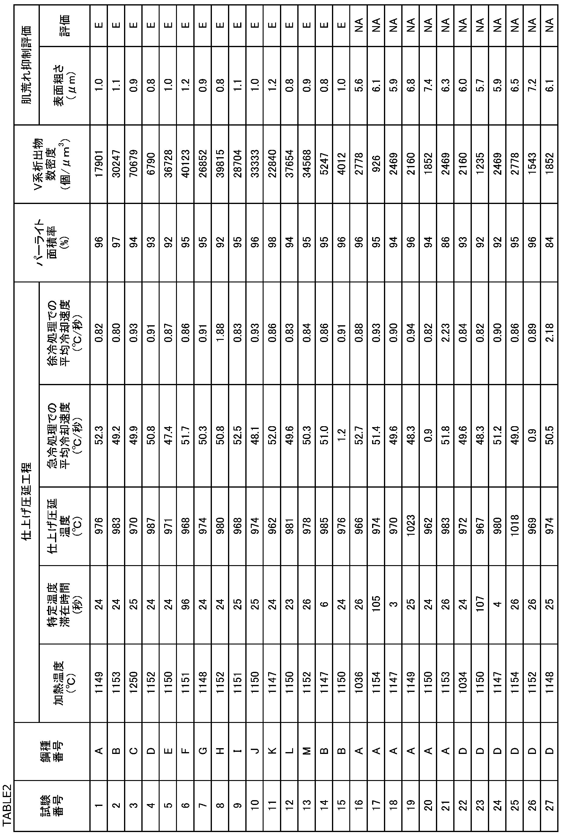
製造された各試験番号の鋼材に対して、ミクロ組織観察試験、V系析出物の数密度測定試験、及び、シェービング処理後肌荒れ評価試験を実施した。
各試験番号の鋼材のミクロ組織中のパーライト面積率(%)を次の方法で測定した。各試験番号の鋼材の線径方向で切断した断面(表面)を観察面とした。観察面を鏡面研磨した。鏡面研磨された観察面に対して、5%ピクリン酸アルコール(ピクラール腐食液)によるエッチングを実施した。エッチングされた観察面のうち、鋼材表面(観察面の外周)から径方向に直径の1/4深さ位置を観察視野とした。10箇所の観察視野を2000倍の走査型電子顕微鏡(SEM)を用いて観察し、10観察視野の写真画像を生成した。各視野のサイズは40μm×60μmとした。
各試験番号の鋼材において、最大径が2~20nmのV系析出物の個数密度(個/μm3)を次の方法で測定した。各試験番号の鋼材(線材)を線径方向に切断した。そして、線径方向の断面を有し、鋼材の中心軸方向の厚さが0.5mmの円板を採取した。エメリー紙を用いて、円板の両側から研削研磨を行い、円板の厚さを60μmとした。その後、円板から直径3mmのサンプルを採取した。サンプルを10%過塩素酸-氷酢酸溶液中に浸漬して、電解研磨を実施して、厚さ100nmの薄膜試料を作成した。
各試験番号の鋼材に対して、シェービング処理工程を実施した。シェービング処理工程では、シェービングダイスを用いてシェービング処理を実施し、鋼材の表面を0.15mm深さまで皮むきした。シェービング処理後の鋼材(以下、試験片という)の表面粗さを測定した。具体的には、JIS B 0601(2013)に規定された十点平均粗さRzを求めた。評価長さは、基準長さ(カットオフ波長)の5倍とした。十点平均粗さRzの測定は、触針式の粗さ計を用いて行った。測定速度は、0.5mm/secとした。測定結果を表2の「表面粗さ(μm)」欄に示す。十点平均粗さRzが5.0μm以下であれば、シェービング処理後の鋼材表面の肌荒れを十分に抑制できたと判断した(表2中の「肌荒れ抑制評価」の「評価」欄で「E」で表記)。一方、十点平均粗さRzが5.0μmを超えれば、シェービング処理後の鋼材表面の肌荒れを十分に抑制できなかったと判断した(表2中の「肌荒れ抑制評価」の「評価」欄で「NA」で表記)。
表2に試験結果を示す。表2を参照して、試験番号1~15は、化学組成が適切であり、かつ、製造工程も適切であった。そのため、各試験番号の鋼材のミクロ組織では、パーライト面積率が90%以上であった。さらに、最大径が2~20nmのV系析出物の数密度はいずれも3000~80000個/μm3であった。そのため、試験番号1~16の鋼材に対して、シェービング処理工程を実施した場合でも、鋼材の表面粗さは5.0μm以下であり、シェービング処理後の肌荒れを十分に抑制することができた。
Claims (2)
- 鋼材であって、
化学組成が、質量%で、
C:0.50~0.80%、
Si:1.20~2.90%、
Mn:0.25~1.00%、
Cr:0.40~1.90%、
V:0.05~0.60%、
P:0.020%以下、
S:0.020%以下、
N:0.0100%以下、
Mo:0~0.50%、
Nb:0~0.050%、
W:0~0.60%、
Ni:0~0.50%、
Co:0~0.30%、
B:0~0.0050%、
Cu:0~0.050%、
Al:0~0.0050%、及び、
Ti:0~0.050%、を含有し、
残部がFe及び不純物からなり、
前記鋼材のミクロ組織において、パーライト面積率が90%以上であり、
前記パーライト中のフェライトにおいて、
最大径が2~20nmのV系析出物の数密度が3000~80000個/μm3である、
鋼材。 - 請求項1に記載の鋼材であって、
前記化学組成は、
Mo:0.01~0.50%、
Nb:0.001~0.050%、
W:0.01~0.60%、
Ni:0.01~0.50%、
Co:0.01~0.30%、及び、
B:0.0001~0.0050%、からなる群から選択される1種以上を含有する、
鋼材。
Priority Applications (5)
| Application Number | Priority Date | Filing Date | Title |
|---|---|---|---|
| DE112021007366.4T DE112021007366T5 (de) | 2021-03-24 | 2021-03-24 | Stahlmaterial |
| JP2023508277A JP7445184B2 (ja) | 2021-03-24 | 2021-03-24 | 鋼材 |
| CN202180096210.3A CN117043372B (zh) | 2021-03-24 | 2021-03-24 | 钢材 |
| US18/548,952 US20240150878A1 (en) | 2021-03-24 | 2021-03-24 | Steel material |
| PCT/JP2021/012350 WO2022201381A1 (ja) | 2021-03-24 | 2021-03-24 | 鋼材 |
Applications Claiming Priority (1)
| Application Number | Priority Date | Filing Date | Title |
|---|---|---|---|
| PCT/JP2021/012350 WO2022201381A1 (ja) | 2021-03-24 | 2021-03-24 | 鋼材 |
Publications (1)
| Publication Number | Publication Date |
|---|---|
| WO2022201381A1 true WO2022201381A1 (ja) | 2022-09-29 |
Family
ID=83396642
Family Applications (1)
| Application Number | Title | Priority Date | Filing Date |
|---|---|---|---|
| PCT/JP2021/012350 Ceased WO2022201381A1 (ja) | 2021-03-24 | 2021-03-24 | 鋼材 |
Country Status (5)
| Country | Link |
|---|---|
| US (1) | US20240150878A1 (ja) |
| JP (1) | JP7445184B2 (ja) |
| CN (1) | CN117043372B (ja) |
| DE (1) | DE112021007366T5 (ja) |
| WO (1) | WO2022201381A1 (ja) |
Citations (5)
| Publication number | Priority date | Publication date | Assignee | Title |
|---|---|---|---|---|
| JP2002180200A (ja) * | 2000-12-20 | 2002-06-26 | Kobe Steel Ltd | 硬引きばね用鋼線材、硬引きばね用伸線材および硬引きばね並びに硬引きばねの製造方法 |
| JP2002180199A (ja) * | 2000-12-20 | 2002-06-26 | Kobe Steel Ltd | 耐へたり性に優れたばね用鋼およびばね用鋼線並びにばね |
| JP2014208900A (ja) * | 2013-03-25 | 2014-11-06 | 株式会社神戸製鋼所 | 伸線加工性、および伸線加工後の曲げ加工性に優れた高強度ばね用鋼線材、およびその製造方法、並びに高強度ばね、およびその製造方法 |
| JP2017179524A (ja) * | 2016-03-31 | 2017-10-05 | 株式会社神戸製鋼所 | 鋼線材ならびに鋼線材および鋼線の製造方法 |
| KR20180073389A (ko) * | 2016-12-22 | 2018-07-02 | 주식회사 포스코 | 신선가공성이 우수한 고강도 선재, 열처리 선재 및 이들의 제조방법 |
Family Cites Families (11)
| Publication number | Priority date | Publication date | Assignee | Title |
|---|---|---|---|---|
| JP2932943B2 (ja) * | 1993-11-04 | 1999-08-09 | 株式会社神戸製鋼所 | 高耐食性高強度ばね用鋼材 |
| DE60129463T2 (de) * | 2000-12-20 | 2008-04-17 | Kabushiki Kaisha Kobe Seiko Sho, Kobe | Walzdraht für hartgezogene feder, gezogener draht für hartgezogene feder und hartgezogene feder und verfahren zur herstellung von hartgezogenen federn |
| JP2007327084A (ja) | 2006-06-06 | 2007-12-20 | Kobe Steel Ltd | 伸線加工性に優れた線材およびその製造方法 |
| CN102181786A (zh) * | 2011-04-25 | 2011-09-14 | 江苏省沙钢钢铁研究院有限公司 | 1670MPa级桥梁缆索镀锌钢丝用盘条及其制备方法 |
| JP6208611B2 (ja) * | 2014-03-31 | 2017-10-04 | 株式会社神戸製鋼所 | 疲労特性に優れた高強度鋼材 |
| CN108350537B (zh) * | 2015-09-04 | 2021-01-08 | 日本制铁株式会社 | 弹簧用钢线及弹簧 |
| US11098394B2 (en) * | 2016-07-05 | 2021-08-24 | Nippon Steel Corporation | Rolled wire rod |
| CN106191655A (zh) * | 2016-08-17 | 2016-12-07 | 安徽红桥金属制造有限公司 | 一种耐磨损抗氧化合金弹簧钢及其热处理工艺 |
| US11952650B2 (en) * | 2019-10-16 | 2024-04-09 | Nippon Steel Corporation | Steel wire |
| CN114555850B (zh) * | 2019-10-16 | 2022-11-01 | 日本制铁株式会社 | 减震器弹簧 |
| US12612675B2 (en) * | 2020-02-21 | 2026-04-28 | Nippon Steel Corporation | Steel wire |
-
2021
- 2021-03-24 WO PCT/JP2021/012350 patent/WO2022201381A1/ja not_active Ceased
- 2021-03-24 JP JP2023508277A patent/JP7445184B2/ja active Active
- 2021-03-24 CN CN202180096210.3A patent/CN117043372B/zh active Active
- 2021-03-24 DE DE112021007366.4T patent/DE112021007366T5/de active Pending
- 2021-03-24 US US18/548,952 patent/US20240150878A1/en active Pending
Patent Citations (5)
| Publication number | Priority date | Publication date | Assignee | Title |
|---|---|---|---|---|
| JP2002180200A (ja) * | 2000-12-20 | 2002-06-26 | Kobe Steel Ltd | 硬引きばね用鋼線材、硬引きばね用伸線材および硬引きばね並びに硬引きばねの製造方法 |
| JP2002180199A (ja) * | 2000-12-20 | 2002-06-26 | Kobe Steel Ltd | 耐へたり性に優れたばね用鋼およびばね用鋼線並びにばね |
| JP2014208900A (ja) * | 2013-03-25 | 2014-11-06 | 株式会社神戸製鋼所 | 伸線加工性、および伸線加工後の曲げ加工性に優れた高強度ばね用鋼線材、およびその製造方法、並びに高強度ばね、およびその製造方法 |
| JP2017179524A (ja) * | 2016-03-31 | 2017-10-05 | 株式会社神戸製鋼所 | 鋼線材ならびに鋼線材および鋼線の製造方法 |
| KR20180073389A (ko) * | 2016-12-22 | 2018-07-02 | 주식회사 포스코 | 신선가공성이 우수한 고강도 선재, 열처리 선재 및 이들의 제조방법 |
Also Published As
| Publication number | Publication date |
|---|---|
| JP7445184B2 (ja) | 2024-03-07 |
| CN117043372B (zh) | 2025-11-11 |
| CN117043372A (zh) | 2023-11-10 |
| US20240150878A1 (en) | 2024-05-09 |
| DE112021007366T5 (de) | 2024-02-15 |
| JPWO2022201381A1 (ja) | 2022-09-29 |
Similar Documents
| Publication | Publication Date | Title |
|---|---|---|
| JP6160783B2 (ja) | 鋼板及びその製造方法 | |
| JP4872846B2 (ja) | 窒化歯車用粗形品および窒化歯車 | |
| EP3282032A1 (en) | Steel sheet with excellent cold workability during forming, and process for producing same | |
| CN109477179B (zh) | 高频淬火用钢 | |
| JP4008320B2 (ja) | 軸受用圧延線材および伸線材 | |
| JP7444097B2 (ja) | 熱延鋼板およびその製造方法 | |
| US12181012B2 (en) | Damper spring | |
| WO2013187409A1 (ja) | 中空ばね用シームレス鋼管 | |
| US11952650B2 (en) | Steel wire | |
| JP2016216809A (ja) | 冷間成形性と熱処理後靭性に優れた低炭素鋼板及び製造方法 | |
| CN113646448B (zh) | 钢轴部件 | |
| WO2022071420A1 (ja) | 鋼材 | |
| JP7445184B2 (ja) | 鋼材 | |
| JP6801721B2 (ja) | 軟磁性部品用鋼材、軟磁性部品、及び、軟磁性部品の製造方法 | |
| JP7334868B2 (ja) | 鋼製部品 | |
| US12612675B2 (en) | Steel wire | |
| CN107429359B (zh) | 热轧棒线材、部件及热轧棒线材的制造方法 | |
| WO2022071419A1 (ja) | 鋼材 | |
| US12338516B2 (en) | Damper spring | |
| JP7321354B2 (ja) | 弁ばね | |
| US12006994B2 (en) | Valve spring | |
| JP7444096B2 (ja) | 熱延鋼板およびその製造方法 |
Legal Events
| Date | Code | Title | Description |
|---|---|---|---|
| 121 | Ep: the epo has been informed by wipo that ep was designated in this application |
Ref document number: 21932991 Country of ref document: EP Kind code of ref document: A1 |
|
| WWE | Wipo information: entry into national phase |
Ref document number: 2023508277 Country of ref document: JP |
|
| WWE | Wipo information: entry into national phase |
Ref document number: 18548952 Country of ref document: US |
|
| WWE | Wipo information: entry into national phase |
Ref document number: 202180096210.3 Country of ref document: CN |
|
| WWE | Wipo information: entry into national phase |
Ref document number: 112021007366 Country of ref document: DE |
|
| 122 | Ep: pct application non-entry in european phase |
Ref document number: 21932991 Country of ref document: EP Kind code of ref document: A1 |