WO2022201298A1 - Drill head, tip-interchangeable drill, and drill - Google Patents
Drill head, tip-interchangeable drill, and drill Download PDFInfo
- Publication number
- WO2022201298A1 WO2022201298A1 PCT/JP2021/011958 JP2021011958W WO2022201298A1 WO 2022201298 A1 WO2022201298 A1 WO 2022201298A1 JP 2021011958 W JP2021011958 W JP 2021011958W WO 2022201298 A1 WO2022201298 A1 WO 2022201298A1
- Authority
- WO
- WIPO (PCT)
- Prior art keywords
- cutting edge
- thinning
- central axis
- flank
- tip
- Prior art date
Links
- 230000002093 peripheral effect Effects 0.000 claims description 38
- 238000010586 diagram Methods 0.000 description 4
- 230000000694 effects Effects 0.000 description 4
- 238000012986 modification Methods 0.000 description 2
- 230000004048 modification Effects 0.000 description 2
- 229910000831 Steel Inorganic materials 0.000 description 1
- 239000000463 material Substances 0.000 description 1
- 239000007787 solid Substances 0.000 description 1
- 239000010959 steel Substances 0.000 description 1
Images


Classifications
-
- B—PERFORMING OPERATIONS; TRANSPORTING
- B23—MACHINE TOOLS; METAL-WORKING NOT OTHERWISE PROVIDED FOR
- B23B—TURNING; BORING
- B23B51/00—Tools for drilling machines
- B23B51/02—Twist drills
-
- B—PERFORMING OPERATIONS; TRANSPORTING
- B23—MACHINE TOOLS; METAL-WORKING NOT OTHERWISE PROVIDED FOR
- B23B—TURNING; BORING
- B23B51/00—Tools for drilling machines
- B23B51/0002—Drills with connected cutting heads, e.g. with non-exchangeable cutting heads; Drills with a single insert extending across the rotational axis and having at least two radially extending cutting edges in the working position
- B23B51/0003—Drills with connected cutting heads, e.g. with non-exchangeable cutting heads; Drills with a single insert extending across the rotational axis and having at least two radially extending cutting edges in the working position with exchangeable heads or inserts
- B23B51/0004—Drills with connected cutting heads, e.g. with non-exchangeable cutting heads; Drills with a single insert extending across the rotational axis and having at least two radially extending cutting edges in the working position with exchangeable heads or inserts with cutting heads or inserts attached by screw means
-
- B—PERFORMING OPERATIONS; TRANSPORTING
- B23—MACHINE TOOLS; METAL-WORKING NOT OTHERWISE PROVIDED FOR
- B23B—TURNING; BORING
- B23B2251/00—Details of tools for drilling machines
- B23B2251/04—Angles, e.g. cutting angles
-
- B—PERFORMING OPERATIONS; TRANSPORTING
- B23—MACHINE TOOLS; METAL-WORKING NOT OTHERWISE PROVIDED FOR
- B23B—TURNING; BORING
- B23B2251/00—Details of tools for drilling machines
- B23B2251/08—Side or plan views of cutting edges
- B23B2251/082—Curved cutting edges
-
- B—PERFORMING OPERATIONS; TRANSPORTING
- B23—MACHINE TOOLS; METAL-WORKING NOT OTHERWISE PROVIDED FOR
- B23B—TURNING; BORING
- B23B2251/00—Details of tools for drilling machines
- B23B2251/14—Configuration of the cutting part, i.e. the main cutting edges
-
- B—PERFORMING OPERATIONS; TRANSPORTING
- B23—MACHINE TOOLS; METAL-WORKING NOT OTHERWISE PROVIDED FOR
- B23B—TURNING; BORING
- B23B2251/00—Details of tools for drilling machines
- B23B2251/18—Configuration of the drill point
- B23B2251/182—Web thinning
Definitions
- the present disclosure relates to drill heads, replaceable tip drills and drills.
- Patent Document 1 describes a drill.
- the drill described in Patent Literature 1 is rotated around its axis.
- the drill described in Patent Document 1 has an outer peripheral surface, a discharge groove, a first flank, a second flank, a cutting edge, a thinning edge, and a gash portion.
- the discharge groove is formed on the outer peripheral surface.
- the discharge groove extends spirally around the axis from the tip end side of the drill toward the rear end side of the drill.
- the discharge groove has an inner surface facing in the direction of rotation of the drill.
- the cutting edge is provided on the ridge between the inner surface of the discharge groove and the first flank.
- the second flank is opposite the first flank across the discharge groove.
- a thinning edge extends from the inner end of the cutting edge toward the chisel.
- the gash portion is connected to the discharge groove.
- the gash portion has a thinning surface connected to the thinning blade from the side opposite to the first flank, and a gash surface connected to the second flank.
- the ridgeline between the gash surface and the second flank is arcuate in an end view viewed along the axial direction from the tip side of the drill.
- the drill head of the present disclosure is rotated around its central axis.
- the drill head has a mounting surface that is an end surface in the direction of the central axis, a tip surface that is the opposite surface to the mounting surface in the direction of the central axis, an outer peripheral surface that is continuous with the mounting surface and the tip surface, and a tip surface that extends from the outer peripheral surface to the center.
- a cutting edge extending toward the axis, a flute formed on the outer peripheral surface and extending spirally around the central axis so as to reach the mounting surface from the tip surface, and a thinning surface connecting to the tip surface and the flute.
- the tip face has a first flank that continues to the cutting edge and a second flank that is opposite to the first flank across the flute.
- the cutting edge has a main cutting edge continuous with the outer peripheral surface and a thinning cutting edge continuous with the main cutting edge and located closer to the central axis than the main cutting edge.
- the main cutting edge includes a first end, which is the end on the outer peripheral surface side, and a second end, which is the end on the thinning cutting edge side.
- the thinning face has a thinning rake face that continues to the thinning cutting edge from the side opposite to the first flank face, and a thinning heel face that connects to the second flank face.
- the recess amount of the main cutting edge with respect to the imaginary straight line connecting the first end and the second end is -0.01 of the diameter of the circumscribed circle of the drill head. It is more than twice and less than 0.02 times.
- the ridge between the thinning heel surface and the second flank is arcuate with a radius of 0.10 to 0.30 times the diameter.
- FIG. 1 is a perspective view of a drill 100.
- FIG. FIG. 2 is a perspective view of the drill head 10.
- FIG. FIG. 3 is a front view of the drill head 10.
- FIG. FIG. 4 is a rear view of the drill head 10.
- FIG. 5 is a schematic diagram for explaining the recess amount of the main cutting edge 15a.
- FIG. 6 is a schematic diagram for explaining the radial rake angle ⁇ 1 of the main cutting edge 15a.
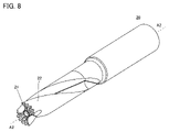
- FIG. 7 is a cross-sectional view along VII-VII in FIG. 8 is a perspective view of the holder 20.
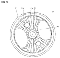
- FIG. FIG. 9 is a front view of the holder 20.
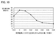
- FIG. FIG. 10 is a graph showing the results of the first cutting test.
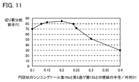
- FIG. 11 is a graph showing the results of the second cutting test.
- FIG. 12 is a graph showing the results of the third cutting test.
- the present disclosure has been made in view of the problems of the prior art as described above. More specifically, the present disclosure provides a drill head that tends to break chips.
- the drill head of the present disclosure facilitates breakage of chips.
- the drill head according to the embodiment is rotated around the central axis.
- the drill head has a mounting surface that is an end surface in the direction of the central axis, a tip surface that is the opposite surface to the mounting surface in the direction of the central axis, an outer peripheral surface that is continuous with the mounting surface and the tip surface, and a tip surface that extends from the outer peripheral surface to the center.
- a cutting edge extending toward the axis, a flute formed on the outer peripheral surface and extending spirally around the central axis so as to reach the mounting surface from the tip surface, and a thinning surface connecting to the tip surface and the flute.
- the tip face has a first flank that continues to the cutting edge and a second flank that is opposite to the first flank across the flute.
- the cutting edge has a main cutting edge continuous with the outer peripheral surface and a thinning cutting edge continuous with the main cutting edge and located closer to the central axis than the main cutting edge.
- the main cutting edge includes a first end, which is the end on the outer peripheral surface side, and a second end, which is the end on the thinning cutting edge side.
- the thinning face has a thinning rake face that continues to the thinning cutting edge from the side opposite to the first flank face, and a thinning heel face that connects to the second flank face.
- the recess amount of the main cutting edge with respect to the imaginary straight line connecting the first end and the second end is -0.01 of the diameter of the circumscribed circle of the drill head. It is more than twice and less than 0.02 times.
- the ridge between the thinning heel surface and the second flank is arcuate with a radius of 0.10 to 0.30 times the diameter.
- the recess amount of the main cutting edge with respect to the imaginary straight line connecting the first end and the second end is It may be 0.00 to 0.01 times the diameter of the drill head.
- the radius of the ridge between the arc-shaped thinning heel surface and the second flank is 0.13 to 0.24 times the diameter of the drill head. There may be.
- the difference between the maximum value and the minimum value of the radial rake angle of the main cutting edge may be 20° or less.
- the angle between the direction of the central axis and the thinning heel surface may be 28° or more and 32° or less.
- the thinning cutting edge may extend linearly in an end view viewed from the tip side along the direction of the central axis.
- a tip replaceable drill includes the drill head of (1) to (6) above and a holder attached to an attachment surface.
- the drill according to the embodiment is rotated around the central axis.
- the drill has a tip and a rear end, which are ends in the direction of the central axis, a tip surface at the tip, an outer peripheral surface connected to the tip surface, a cutting edge extending from the outer peripheral surface toward the central axis at the tip surface,
- a flute is formed on the outer peripheral surface and extends spirally around the central axis from the front end surface toward the rear end side, and a thinning surface is provided that continues to the front end surface and the flute.
- the tip face has a first flank that continues to the cutting edge and a second flank that is opposite to the first flank across the flute.
- the cutting edge has a main cutting edge continuous with the outer peripheral surface and a thinning cutting edge continuous with the main cutting edge and located closer to the central axis than the main cutting edge.
- the main cutting edge includes a first end, which is the end on the outer peripheral surface side, and a second end, which is the end on the thinning cutting edge side.
- the thinning face has a thinning rake face that continues to the thinning cutting edge from the side opposite to the first flank face, and a thinning heel face that connects to the second flank face.
- the recess amount of the main cutting edge with respect to the imaginary straight line connecting the first end and the second end is -0.01 times the diameter of the circumscribed circle of the drill. 0.02 times or less.
- the ridge between the thinning heel surface and the second flank is arcuate with a radius of 0.10 to 0.30 times the diameter.
- drill 100 A drill according to an embodiment (hereinafter referred to as "drill 100") will be described.
- the drill 100 is a replaceable tip type drill.
- FIG. 1 is a perspective view of the drill 100.
- the drill 100 is rotated about a central axis A as shown in FIG.
- Drill 100 has a leading end 100a and a trailing end 100b.
- the trailing end 100b is the opposite end in the direction of the central axis A from the leading end 100a.
- Leading edge 100a and trailing edge 100b are the ends of drill 100 in the direction of central axis A. As shown in FIG.
- the drill 100 has a drill head 10, a holder 20 and a fixing member 30.
- the drill head 10 is on the tip 100a side of the drill 100 .
- the holder 20 is on the rear end 100b side of the drill 100 .
- FIG. 10 is made of cemented carbide, for example.
- FIG. 2 is a perspective view of the drill head 10.
- FIG. 3 is a front view of the drill head 10.
- FIG. 4 is a rear view of the drill head 10.
- the drill head 10 is rotated around a central axis A1.
- the central axis A1 is on the same straight line as the central axis A.
- the drill head 10 has a mounting surface 11, a tip surface 12, and an outer peripheral surface 13.
- the mounting surface 11 and the tip surface 12 are end surfaces of the drill head 10 in the direction of the central axis A1.
- the mounting surface 11 faces the holder 20 side.
- the tip surface 12 is the opposite surface of the mounting surface 11 in the direction of the central axis A1.
- the tip face 12 is at the tip 100a.
- the outer peripheral surface 13 continues to the mounting surface 11 and the tip surface 12 .
- a plurality of grooves 11a are formed on the mounting surface 11.
- the mounting surface 11 is recessed toward the tip surface 12 in the groove 11a.
- the groove 11a extends from the central portion of the mounting surface 11 toward the outer peripheral surface 13 along the direction orthogonal to the central axis A1.
- the diameter of the circumscribed circle of the drill head 10 be the outer diameter D1 in the end view seen from the tip surface 12 side along the direction of the central axis A1. In FIG. 3, this circumscribed circle is indicated by a dotted line.
- the outer diameter D1 is, for example, 12 mm or more.
- the outer diameter D1 may be 10 mm or more.
- Two flutes 14 are formed on the outer peripheral surface 13 .
- the flute 14 is spirally formed around the central axis A ⁇ b>1 so as to reach the attachment surface 11 from the tip surface 12 . From another point of view, the flute 14 extends spirally around the central axis A1 from the front end surface 12 toward the rear end 100b.
- One flute 14 is positioned symmetrically to the other flute 14 with respect to the central axis A1 in an end view viewed from the tip surface 12 along the direction of the central axis A1.
- the drill head 10 has two cutting edges 15.
- the cutting edge 15 extends from the outer peripheral surface 13 toward the central axis A1 on the tip surface 12 .
- the cutting edge 15 has a main cutting edge 15a and a thinning cutting edge 15b.
- the thinning cutting edge 15b is closer to the central axis A1 than the main cutting edge 15a.
- One cutting edge 15 is located symmetrically with respect to the other cutting edge 15 and the central axis A1 in an end view viewed from the tip surface 12 along the direction of the central axis A1.
- the main cutting edge 15a has a first end 15aa and a second end 15ab.
- the first end 15aa is the end on the outer peripheral surface 13 side.
- the second end 15ab is the end opposite to the first end 15aa.
- the main cutting edge 15a continues to the thinning cutting edge 15b at the second end 15ab.
- the main cutting edge 15a extends substantially linearly along the direction of the central axis A1 in an end view viewed from the tip end face 12 side.
- the thinning cutting edge 15b preferably extends linearly in an end view viewed from the tip surface 12 along the direction of the central axis A1.
- FIG. 5 is a schematic diagram for explaining the recess amount of the main cutting edge 15a.
- FIG. 5 shows the shape of the main cutting edge 15a when the tip surface 12 is viewed in the direction from the tip 100a to the rear end 100b.
- the direction substantially perpendicular to the main cutting edge 15a is shown enlarged from the direction substantially parallel to the main cutting edge 15a.
- a virtual straight line connecting the first end 15aa and the second end 15ab is defined as a virtual straight line L1.
- the distance between the imaginary straight line L1 and the main cutting edge 15a is defined as the distance DIS.
- the maximum value of the distance DIS is the amount of depression of the main cutting edge 15a with respect to the imaginary straight line L1.
- the amount of recession of the main cutting edge 15a with respect to the imaginary straight line L1 is -0.01 times or more and 0.02 times or less of the outer diameter D1.
- the recess amount of the main cutting edge 15a with respect to the imaginary straight line L1 is 0.00 to 0.01 times the outer diameter D1. Note that when the main cutting edge 15a protrudes with respect to the straight line L, the recess amount of the main cutting edge 15a becomes a negative value. Further, when the main cutting edge 15a is recessed from the straight line L, the recess amount of the main cutting edge 15a becomes a positive value.
- the amount of recession of the main cutting edge 15a shown in FIG. 5 with respect to the imaginary straight line L1 is a positive value.
- FIG. 6 is a schematic diagram for explaining the radial rake angle ⁇ 1 of the main cutting edge 15a.
- FIG. 6 shows the shape of the main cutting edge 15a when the tip surface 12 is viewed in the direction from the tip 100a to the rear end 100b.
- the direction substantially perpendicular to the main cutting edge 15a is shown enlarged from the direction substantially parallel to the main cutting edge 15a.
- a specific position on the main cutting edge 15a is defined as position P1.
- a virtual straight line connecting the central axis A1 and the position P1 is assumed to be a virtual straight line L2.
- the angle formed by the tangent to the main cutting edge 15a at the position P1 and the imaginary straight line L2 is the radial rake angle ⁇ 1 of the main cutting edge 15a.
- the difference between the maximum value and the minimum value of the radial rake angle ⁇ 1 of the main cutting edge 15a is preferably 20° or less.
- the tip surface 12 has two first flanks 12a and two second flanks 12b.
- the first flank 12a continues to the cutting edge 15 (main cutting edge 15a and thinning cutting edge 15b).
- One first flank 12a is symmetrical to the other first flank 12a with respect to the central axis A1.
- the flute 14 continues from the side opposite to the first flank 12a to the main cutting edge 15a. That is, the main cutting edge 15a is located on the ridge line between the first flank 12a and the flute 14.
- the second flank 12b is on the opposite side of the flute 14 from the first flank 12a.
- One of the second flanks 12b is symmetrical to the other of the second flanks 12b with respect to the central axis A1.
- the drill head 10 has a thinning surface 16 as shown in FIG.
- the thinning surface 16 is continuous with the tip surface 12 and the flutes 14 .
- the thinning surface 16 has a thinning rake surface 16a and a thinning heel surface 16b.
- the thinning rake face 16a continues to the thinning cutting edge 15b from the side opposite to the first flank face 12a. That is, the thinning cutting edge 15b is located on the ridge between the first flank 12a and the thinning rake face 16a.
- the thinning heel surface 16b continues to the second flank 12b. As shown in FIG. 3, in an end view viewed from the tip end surface 12 side along the direction of the central axis A1, the ridgeline between the thinning heel surface 16b and the second flank surface 12b is arcuate.
- This arc has a radius of curvature corresponding to a given point on the arc.
- the arc may have substantially the same radius of curvature for all points of the arc.
- the arc shape may have different radii of curvature corresponding to points on the arc.
- the “radius” of an arc means the range of values of radius of curvature corresponding to all points of the arc.
- the radius of this circular arc is 0.10 to 0.30 times the outer diameter D1.
- the radius of this circular arc is preferably 0.13 to 0.24 times the outer diameter D1.
- a ridge line between the thinning heel surface 16 b and the second flank surface 12 b may be divided by the through hole 17 .
- the shape of the portion of the ridgeline between the thinning heel surface 16b and the second flank surface 12b on the side closer to the central axis A1. may be arc-shaped.
- the radius of this circular arc is 0.10 to 0.30 times the outer diameter D1.
- the radius of this circular arc is preferably 0.13 to 0.24 times the outer diameter D1.
- FIG. 7 is a cross-sectional view along VII-VII in FIG.
- FIG. 7 shows a cross section of the drill head 10 parallel to the thinning rake face 16a.
- the angle formed by the thinning heel surface 16b and the central axis A1 is defined as an angle ⁇ 2.
- the angle ⁇ 2 is preferably 28° or more and 32° or less.
- the drill head 10 has two through holes 17 formed therein.
- the through hole 17 penetrates the drill head 10 along the direction of the central axis A1.
- One through hole 17 is located symmetrically with the other through hole 17 with respect to the central axis A1.
- the end of the through hole 17 on the side of the tip surface 12 opens at the second flank 12b.
- the holder 20 is made of steel, for example. 8 is a perspective view of the holder 20.
- FIG. FIG. 9 is a front view of the holder 20.
- the central axis A2 is on the same straight line as the central axis A1.
- the holder 20 has a mounting surface 21 and an outer peripheral surface 22 .
- the mounting surface 21 is an end surface of the holder 20 in the direction of the central axis A2 and faces the drill head 10 side.
- the outer peripheral surface 22 continues to the mounting surface 21 .
- a plurality of ridges 21 a are formed on the mounting surface 21 .
- the mounting surface 21 protrudes toward the drill head 10 at the protruding line 21a.
- the ridge 21a extends from the central portion of the mounting surface 21 toward the outer peripheral surface 22 along the direction perpendicular to the central axis A2.
- the mounting surface 21 is formed with two screw holes 21b.
- the screw hole 21b extends from the mounting surface 21 toward the rear end 100b.
- One screw hole 21b is located symmetrically to the other screw hole 21b with respect to the central axis A2.
- the ridge 21a is fitted into the groove 11a.
- the screw hole 21b is positioned so as to overlap the through hole 17 when the ridge 21a is fitted in the groove 11a.
- the fixing member 30 is, for example, a screw. The fixing member 30 fastens the drill head 10 to the holder 20 by being passed through the through hole 17 and screwed into the screw hole 21b. Thus, the holder 20 is attached to the drill head 10 (attachment surface 11).
- the main cutting edge 15a extends substantially linearly. That is, in the drill 100, the recess amount of the main cutting edge 15a with respect to the imaginary straight line L1 is -0.01 times or more and 0.02 times or less of the outer diameter D1. Therefore, in the drill 100, the distortion of the chip portion generated by the main cutting edge 15a is small, and the crack generated in the chip portion generated by the thinning cutting edge 15b is reduced to the chip generated by the main cutting edge 15a. It is easy to progress to the part of
- the ridgeline between the thinning heel surface 16b and the second flank surface 12b is arcuate with a radius of 0.10 to 0.30 times the outer diameter D1. Therefore, in the drill 100, the chip portion generated by the thinning cutting edge 15b is likely to be curved by the thinning heel surface 16b, and cracks are likely to occur in the chip portion generated by the thinning cutting edge 15b.
- the angle ⁇ 2 When the angle ⁇ 2 is large, chips may remain in the thinning, and cracks may be less likely to occur in the chips generated by the thinning cutting edge 15b. On the other hand, when the angle ⁇ 2 is small, it becomes difficult for the chips generated by the thinning cutting edge 15b to bend (hardly crack) due to contact with the thinning heel surface 16b. Therefore, by optimizing the range of the angle ⁇ 2 (more specifically, the angle ⁇ 2 is set to 28° or more and 32° or less), chips are more likely to be divided.
- the thinning cutting edge 15b extends linearly in an end view viewed from the tip surface 12 side along the direction of the central axis A1
- the distortion of the chip portion generated by the thinning cutting edge 15b is reduced, and generation It becomes easy for the generated cracks to propagate through the chips generated by the thinning cutting edge 15b. Therefore, in this case, chips are more likely to be divided.
- ⁇ Cutting test> In order to confirm the effect of the drill 100, a first cutting test, a second cutting test and a third cutting test were conducted.
- drills 100 with sample numbers 1-1 to 1-7 were used.
- the radius of the ridge line between the arc-shaped thinning heel surface 16b and the second flank surface 12b was set to 0.20 times the outer diameter D1, and the angle ⁇ 2 was set to 30°.
- the recess amount of the main cutting edge 15a with respect to the virtual straight line L1 was changed within a range of -0.01 times or more and 0.06 times or less of the outer diameter D1.
- drills 100 with sample numbers 2-1 to 2-8 were used.
- the recess amount of the main cutting edge 15a with respect to the virtual straight line L1 was set to 0.00 times the outer diameter D1
- the angle ⁇ 2 was set to 30°.
- the radius of the ridge line between the arc-shaped thinning heel surface 16b and the second flank surface 12b was changed within the range of 0.10 times or more and 0.40 times or less as large as the outer diameter D1.
- FIG. 10 is a graph showing the results of the first cutting test.
- the horizontal axis in FIG. 10 is the value obtained by dividing the recess amount of the main cutting edge 15a with respect to the imaginary straight line L1 by the outer diameter D1
- the vertical axis in FIG. 10 is the chip splitting ratio (unit: percent). Chip Break Percentage is the weight of chips broken by one curl divided by the total weight of chips produced.
- FIG. 11 is a graph showing the results of the second cutting test.
- the horizontal axis in FIG. 11 is the value obtained by dividing the radius of the ridgeline between the arc-shaped thinning heel surface 16b and the second flank surface 12b by the outer diameter D1
- the vertical axis in FIG. 11 is the chip splitting ratio.
- the chip splitting ratio is 50%. That was it.
- the chip splitting ratio was less than 50%.
- the amount of recession of the main cutting edge 15a with respect to the imaginary straight line L1 is within the range of -0.01 times or more and 0.02 times or less of the outer diameter D1, and the arc-shaped thinning heel surface 16b and the second relief It has also been experimentally clarified that when the radius of the ridgeline with the surface 12b is in the range of 0.10 to 0.30 times the outer diameter D1, chips are easily split.
- the chip splitting ratio was 77% or more. From this, it is experimentally confirmed that chips are more likely to be broken when the recess amount of the main cutting edge 15a with respect to the virtual straight line L1 is in the range of 0.00 to 0.01 times the outer diameter D1. was also revealed.
- the chip splitting ratio is 80% or more. had become Therefore, the chips are further divided by setting the radius of the ridgeline between the arc-shaped thinning heel surface 16b and the second flank surface 12b to be in the range of 0.13 to 0.24 times the outer diameter D1. It has also been found experimentally to be easier.
- drills 100 with sample numbers 3-1 to 3-7 were used.
- the amount of recession of the main cutting edge 15a with respect to the virtual straight line L1 was set to 0.00 times the outer diameter D1
- the radius of the ridgeline between the arc-shaped thinning heel surface 16b and the second flank surface 12b was set to the outer diameter. 0.20 times D1.
- the angle ⁇ 2 was changed within the range of 25° or more and 45° or less.
- FIG. 12 is a graph showing the results of the third cutting test.
- the horizontal axis in FIG. 12 is the angle ⁇ 2 (unit:°).
- the vertical axis in FIG. 12 is the chip splitting rate (unit: percent).
- the angle .theta.2 is in the range of 28.degree. to 32.degree. From this, it has been experimentally clarified that chips are more likely to be split when the angle ⁇ 2 is in the range of 28° or more and 32° or less.
- the drill 100 is an indexable drill in the above description, the drill 100 may be a solid drill. That is, the drill 100 does not have to be divided into the drill head 10 and the holder 20 .
- 10 drill head 11 mounting surface, 11a groove, 12 tip surface, 12a first flank, 12b second flank, 13 outer peripheral surface, 14 flute, 15 cutting edge, 15a main cutting edge, 15aa first end, 15ab third 2 ends, 15b thinning cutting edge, 16 thinning surface, 16a thinning rake surface, 16b thinning heel surface, 17 through hole, 20 holder, 21 mounting surface, 21a ridge, 21b screw hole, 22 outer peripheral surface, 30 fixing member, 100 Drill, 100a tip, 100b rear end, A, A1, A2 central axis, D1, D2 outside diameter, DIS distance, L straight line, L1, L2 imaginary straight line, P1 position, ⁇ 1 radial rake angle, ⁇ 2 angle.
Abstract
Description
特許文献1に記載のドリルでは、ドリルの先端側から軸心の方向に沿って見た端面視において、切れ刃が円弧状に延びている。そのため、特許文献1に記載のドリルでは、切れ刃から切り出された切り屑が湾曲し、分断されがたい。 [Problems to be Solved by the Present Disclosure]
In the drill described in
本開示のドリルヘッドによると、切り屑が分断されやすくなる。 [Effect of the present disclosure]
The drill head of the present disclosure facilitates breakage of chips.
まず、本開示の実施形態を列挙して説明する。 [Description of Embodiments of the Present Disclosure]
First, embodiments of the present disclosure will be enumerated and described.
(2)上記(1)のドリルヘッドでは、中心軸の方向に沿って先端面側から見た端面視において、第1端及び第2端を結んだ仮想直線に対する主切れ刃の凹み量が、ドリルヘッドの直径の0.00倍以上0.01倍以下であってもよい。 According to the drill head of (1) above, chips are easily broken.
(2) In the drill head of (1) above, in an end view viewed from the tip surface side along the direction of the central axis, the recess amount of the main cutting edge with respect to the imaginary straight line connecting the first end and the second end is It may be 0.00 to 0.01 times the diameter of the drill head.
(4)上記(1)から(3)のドリルヘッドでは、主切れ刃の半径方向すくい角の最大値と最小値との差が、20°以下であってもよい。 According to the drill head of (3) above, chips are more likely to be divided.
(4) In the drill heads (1) to (3) above, the difference between the maximum value and the minimum value of the radial rake angle of the main cutting edge may be 20° or less.
(6)上記(1)から(5)のドリルヘッドでは、中心軸の方向に沿って先端面側から見た端面視において、シンニング切れ刃が、直線状に延びていてもよい。 According to the drill head of (5) above, chips are more likely to be divided.
(6) In the drill heads (1) to (5) above, the thinning cutting edge may extend linearly in an end view viewed from the tip side along the direction of the central axis.
(7)実施形態に係る先端交換式ドリルは、上記(1)から(6)のドリルヘッドと、取り付け面に取り付けられているホルダとを備える。 According to the drill head of (6) above, chips are more likely to be divided.
(7) A tip replaceable drill according to an embodiment includes the drill head of (1) to (6) above and a holder attached to an attachment surface.
[本開示の実施態様の詳細]
本開示の実施形態の詳細を、図面を参照しながら説明する。以下の図面では、同一又は相当する部分に同一の参照符号を付し、重複する説明は繰り返さない。 According to the drill of (8) above, chips are easily divided.
[Details of Embodiments of the Present Disclosure]
Details of embodiments of the present disclosure will be described with reference to the drawings. In the drawings below, the same or corresponding parts are denoted by the same reference numerals, and redundant description will not be repeated.
以下に、ドリル100の構成を説明する。 (Configuration of drill 100)
The configuration of the
ドリルヘッド10は、例えば、超硬合金により形成されている。図2は、ドリルヘッド10の斜視図である。図3は、ドリルヘッド10の正面図である。図4は、ドリルヘッド10の背面図である。図2、図3及び図4に示されるように、ドリルヘッド10は、中心軸A1の回りに回転される。中心軸A1は、中心軸Aと同一直線上にある。 <Detailed Configuration of
The
ホルダ20は、例えば鋼により形成されている。図8は、ホルダ20の斜視図である。図9は、ホルダ20の正面図である。図8及び図9に示されるように、ホルダ20は、中心軸A2の回りに回転される。中心軸A2は、中心軸A1と同一直線上にある。ホルダ20は、取り付け面21と外周面22とを有している。取り付け面21は、中心軸A2の方向におけるホルダ20の端面であり、ドリルヘッド10側を向いている。外周面22は、取り付け面21に連なっている。 <Detailed Configuration of
The
以下に、ドリル100の効果を説明する。 (Effect of drill 100)
The effects of the
ドリル100の効果を確認するために、第1切削試験、第2切削試験及び第3切削試験を行った。 <Cutting test>
In order to confirm the effect of the


上記においては、ドリル100が刃先交換式のドリルである例を説明したが、ドリル100は、ソリッドドリルであってもよい。すなわち、ドリル100は、ドリルヘッド10及びホルダ20に分割されていなくてもよい。 (Modification)
Although the
Claims (8)
- 中心軸の回りに回転されるドリルヘッドであって、
前記中心軸の方向における端面である取り付け面と、
前記中心軸の方向における前記取り付け面の反対面である先端面と、
前記取り付け面及び前記先端面に連なる外周面と、
前記先端面において前記外周面から前記中心軸に向かって延びている切れ刃と、
前記外周面に形成され、かつ前記先端面から前記取り付け面に達するように前記中心軸回りの螺旋状に延びているフルートと、
前記先端面及び前記フルートに連なるシンニング面とを備え、
前記先端面は、前記切れ刃に連なる第1逃げ面と、前記フルートを挟んで前記第1逃げ面とは反対側にある第2逃げ面とを有し、
前記切れ刃は、前記外周面に連なる主切れ刃と、前記主切れ刃に連なり、かつ前記主切れ刃よりも前記中心軸側にあるシンニング切れ刃とを有し、
前記主切れ刃は、前記外周面側の端である第1端と、前記シンニング切れ刃側の端である第2端とを含み、
前記シンニング面は、前記第1逃げ面とは反対側から前記シンニング切れ刃に連なるシンニングすくい面と、前記第2逃げ面に連なるシンニングヒール面とを有し、
前記中心軸の方向に沿って前記先端面側から見た端面視において、前記第1端及び前記第2端を結んだ仮想直線に対する前記主切れ刃の凹み量は、前記ドリルヘッドの外接円の直径の-0.01倍以上0.02倍以下であり、
前記端面視において、前記シンニングヒール面と前記第2逃げ面との稜線は、半径が前記直径の0.10倍以上0.30倍以下の円弧状である、ドリルヘッド。 A drill head rotated about a central axis,
a mounting surface that is an end surface in the direction of the central axis;
a tip surface opposite to the mounting surface in the direction of the central axis;
an outer peripheral surface continuous with the mounting surface and the tip surface;
A cutting edge extending from the outer peripheral surface toward the central axis on the tip surface;
a flute formed on the outer peripheral surface and extending spirally around the central axis so as to reach the mounting surface from the tip end surface;
A thinning surface connected to the tip surface and the flute,
The tip surface has a first flank that continues to the cutting edge and a second flank that is opposite to the first flank across the flute,
The cutting edge has a main cutting edge connected to the outer peripheral surface and a thinning cutting edge connected to the main cutting edge and located closer to the central axis than the main cutting edge,
The main cutting edge includes a first end that is the end on the outer peripheral surface side and a second end that is the end on the thinning cutting edge side,
The thinning face has a thinning rake face continuous with the thinning cutting edge from the side opposite to the first flank, and a thinning heel face continuous with the second flank,
In an end view viewed from the tip end side along the direction of the central axis, the recess amount of the main cutting edge with respect to the imaginary straight line connecting the first end and the second end is the circumscribed circle of the drill head. -0.01 times or more and 0.02 times or less of the diameter,
The drill head, wherein, in the end view, a ridgeline between the thinning heel surface and the second flank surface is arcuate with a radius of 0.10 to 0.30 times the diameter. - 前記端面視において、前記凹み量は前記直径の0.00倍以上0.01倍以下である、請求項1に記載のドリルヘッド。 The drill head according to claim 1, wherein the recess amount is 0.00 to 0.01 times the diameter in the end view.
- 前記半径は、前記直径の0.13倍以上0.24倍以下である、請求項1又は請求項2に記載のドリルヘッド。 The drill head according to claim 1 or claim 2, wherein said radius is 0.13 times or more and 0.24 times or less of said diameter.
- 前記主切れ刃の半径方向すくい角は、最大値と最小値との差が20°以下である、請求項1から請求項3のいずれか1項に記載のドリルヘッド。 The drill head according to any one of claims 1 to 3, wherein the difference between the maximum value and the minimum value of the radial rake angle of the main cutting edge is 20° or less.
- 前記中心軸の方向と前記シンニングヒール面との間の角度は、28°以上32°以下である、請求項1から請求項4のいずれか1項に記載のドリルヘッド。 The drill head according to any one of claims 1 to 4, wherein the angle between the direction of the central axis and the thinning heel surface is 28° or more and 32° or less.
- 前記端面視において、前記シンニング切れ刃は、直線状に延びている、請求項1から請求項5のいずれか1項に記載のドリルヘッド。 The drill head according to any one of claims 1 to 5, wherein the thinning cutting edge extends linearly in the end view.
- 請求項1から請求項6のいずれか1項に記載の前記ドリルヘッドと、
前記取り付け面に取り付けられているホルダとを備える、先端交換式ドリル。 The drill head according to any one of claims 1 to 6;
and a holder attached to the mounting surface. - 中心軸の回りに回転されるドリルであって、
前記中心軸の方向における端である先端及び後端と、
前記先端にある先端面と、
前記先端面に連なる外周面と、
前記先端面において前記外周面から前記中心軸に向かって延びている切れ刃と、
前記外周面に形成され、かつ前記先端面から前記後端側に向かって前記中心軸回りの螺旋状に延びているフルートと、
前記先端面及び前記フルートに連なるシンニング面とを備え、
前記先端面は、前記切れ刃に連なる第1逃げ面と、前記フルートを挟んで前記第1逃げ面とは反対側にある第2逃げ面とを有し、
前記切れ刃は、前記外周面に連なる主切れ刃と、前記主切れ刃に連なり、かつ前記主切れ刃よりも前記中心軸側にあるシンニング切れ刃とを有し、
前記主切れ刃は、前記外周面側の端である第1端と、前記シンニング切れ刃側の端である第2端とを含み、
前記シンニング面は、前記第1逃げ面とは反対側から前記シンニング切れ刃に連なるシンニングすくい面と、前記第2逃げ面に連なるシンニングヒール面とを有し、
前記中心軸の方向に沿って前記先端面側から見た端面視において、前記第1端及び前記第2端を結んだ仮想直線に対する前記主切れ刃の凹み量は、前記ドリルの外接円の直径の-0.01倍以上0.02倍以下であり、
前記端面視において、前記シンニングヒール面と前記第2逃げ面との稜線は、半径が前記直径の0.10倍以上0.30倍以下の円弧状である、ドリル。 A drill rotated about a central axis,
a leading end and a trailing end, which are ends in the direction of the central axis;
a tip surface at the tip;
an outer peripheral surface continuous with the tip surface;
A cutting edge extending from the outer peripheral surface toward the central axis on the tip surface;
a flute formed on the outer peripheral surface and extending spirally around the central axis from the front end surface toward the rear end;
A thinning surface connected to the tip surface and the flute,
The tip surface has a first flank that continues to the cutting edge and a second flank that is opposite to the first flank across the flute,
The cutting edge has a main cutting edge connected to the outer peripheral surface and a thinning cutting edge connected to the main cutting edge and located closer to the central axis than the main cutting edge,
The main cutting edge includes a first end that is the end on the outer peripheral surface side and a second end that is the end on the thinning cutting edge side,
The thinning face has a thinning rake face continuous with the thinning cutting edge from the side opposite to the first flank, and a thinning heel face continuous with the second flank,
In an end view viewed from the tip end side along the direction of the central axis, the recess amount of the main cutting edge with respect to the imaginary straight line connecting the first end and the second end is the diameter of the circumscribed circle of the drill. -0.01 times or more and 0.02 times or less of
The drill, wherein a ridgeline between the thinning heel surface and the second flank surface is arcuate with a radius of 0.10 times or more and 0.30 times or less as large as the diameter in the end view.
Priority Applications (4)
| Application Number | Priority Date | Filing Date | Title |
|---|---|---|---|
| PCT/JP2021/011958 WO2022201298A1 (en) | 2021-03-23 | 2021-03-23 | Drill head, tip-interchangeable drill, and drill |
| EP21932908.3A EP4316710A1 (en) | 2021-03-23 | 2021-03-23 | Drill head, tip-interchangeable drill, and drill |
| CN202180081811.7A CN116615298A (en) | 2021-03-23 | 2021-03-23 | Bit head, front end replacement type bit and bit |
| JP2021576418A JP7095832B1 (en) | 2021-03-23 | 2021-03-23 | Drill head, replaceable tip drill and drill |
Applications Claiming Priority (1)
| Application Number | Priority Date | Filing Date | Title |
|---|---|---|---|
| PCT/JP2021/011958 WO2022201298A1 (en) | 2021-03-23 | 2021-03-23 | Drill head, tip-interchangeable drill, and drill |
Publications (1)
| Publication Number | Publication Date |
|---|---|
| WO2022201298A1 true WO2022201298A1 (en) | 2022-09-29 |
Family
ID=82308085
Family Applications (1)
| Application Number | Title | Priority Date | Filing Date |
|---|---|---|---|
| PCT/JP2021/011958 WO2022201298A1 (en) | 2021-03-23 | 2021-03-23 | Drill head, tip-interchangeable drill, and drill |
Country Status (4)
| Country | Link |
|---|---|
| EP (1) | EP4316710A1 (en) |
| JP (1) | JP7095832B1 (en) |
| CN (1) | CN116615298A (en) |
| WO (1) | WO2022201298A1 (en) |
Citations (12)
| Publication number | Priority date | Publication date | Assignee | Title |
|---|---|---|---|---|
| US4756650A (en) * | 1986-11-26 | 1988-07-12 | Kabushiki Kaisha Kobe Seiko Sho | Twist drill |
| JPH0263912U (en) * | 1988-11-02 | 1990-05-14 | ||
| JPH1058291A (en) * | 1996-08-19 | 1998-03-03 | O S G Kk | Drill grinding method and drill |
| JP2006231468A (en) * | 2005-02-25 | 2006-09-07 | Osg Corp | Nonferrous metal machining twist drill |
| JP2013215857A (en) * | 2012-04-11 | 2013-10-24 | Sumitomo Electric Hardmetal Corp | Cutting edge replaceable drill |
| JP2014087873A (en) * | 2012-10-30 | 2014-05-15 | Sumitomo Electric Hardmetal Corp | Two-blade double margin drill |
| JP2017042879A (en) * | 2015-08-27 | 2017-03-02 | 三菱マテリアル株式会社 | drill |
| JP2017077597A (en) * | 2015-10-20 | 2017-04-27 | 日進工具株式会社 | drill |
| WO2019049257A1 (en) | 2017-09-07 | 2019-03-14 | オーエスジー株式会社 | Drill |
| JP2019171493A (en) * | 2018-03-27 | 2019-10-10 | 三菱マテリアル株式会社 | Drill |
| JP6750790B1 (en) * | 2019-10-15 | 2020-09-02 | 住友電工ハードメタル株式会社 | Drill |
| JP2021011013A (en) * | 2019-07-08 | 2021-02-04 | 三菱マテリアル株式会社 | Drill |
Family Cites Families (5)
| Publication number | Priority date | Publication date | Assignee | Title |
|---|---|---|---|---|
| JP3515168B2 (en) * | 1994-05-13 | 2004-04-05 | 三菱マテリアル株式会社 | Drill |
| JP2012030306A (en) * | 2010-07-29 | 2012-02-16 | Hitachi Tool Engineering Ltd | Drill and drilling method using the same |
| JP5927671B2 (en) * | 2012-10-25 | 2016-06-01 | 住友電工ハードメタル株式会社 | Small diameter drill |
| JP7352106B2 (en) * | 2018-03-16 | 2023-09-28 | 株式会社Moldino | Drill |
| US11865626B2 (en) * | 2019-08-30 | 2024-01-09 | Osg Corporation | Drill |
-
2021
- 2021-03-23 CN CN202180081811.7A patent/CN116615298A/en active Pending
- 2021-03-23 EP EP21932908.3A patent/EP4316710A1/en active Pending
- 2021-03-23 WO PCT/JP2021/011958 patent/WO2022201298A1/en active Application Filing
- 2021-03-23 JP JP2021576418A patent/JP7095832B1/en active Active
Patent Citations (12)
| Publication number | Priority date | Publication date | Assignee | Title |
|---|---|---|---|---|
| US4756650A (en) * | 1986-11-26 | 1988-07-12 | Kabushiki Kaisha Kobe Seiko Sho | Twist drill |
| JPH0263912U (en) * | 1988-11-02 | 1990-05-14 | ||
| JPH1058291A (en) * | 1996-08-19 | 1998-03-03 | O S G Kk | Drill grinding method and drill |
| JP2006231468A (en) * | 2005-02-25 | 2006-09-07 | Osg Corp | Nonferrous metal machining twist drill |
| JP2013215857A (en) * | 2012-04-11 | 2013-10-24 | Sumitomo Electric Hardmetal Corp | Cutting edge replaceable drill |
| JP2014087873A (en) * | 2012-10-30 | 2014-05-15 | Sumitomo Electric Hardmetal Corp | Two-blade double margin drill |
| JP2017042879A (en) * | 2015-08-27 | 2017-03-02 | 三菱マテリアル株式会社 | drill |
| JP2017077597A (en) * | 2015-10-20 | 2017-04-27 | 日進工具株式会社 | drill |
| WO2019049257A1 (en) | 2017-09-07 | 2019-03-14 | オーエスジー株式会社 | Drill |
| JP2019171493A (en) * | 2018-03-27 | 2019-10-10 | 三菱マテリアル株式会社 | Drill |
| JP2021011013A (en) * | 2019-07-08 | 2021-02-04 | 三菱マテリアル株式会社 | Drill |
| JP6750790B1 (en) * | 2019-10-15 | 2020-09-02 | 住友電工ハードメタル株式会社 | Drill |
Also Published As
| Publication number | Publication date |
|---|---|
| CN116615298A (en) | 2023-08-18 |
| JP7095832B1 (en) | 2022-07-05 |
| JPWO2022201298A1 (en) | 2022-09-29 |
| EP4316710A1 (en) | 2024-02-07 |
Similar Documents
| Publication | Publication Date | Title |
|---|---|---|
| JP5365298B2 (en) | Drill inserts and insert drills | |
| JP5266813B2 (en) | End mill | |
| US8845241B2 (en) | Radius end mill and cutting insert | |
| WO2010050391A1 (en) | Ball end mill | |
| US8277152B2 (en) | End mill | |
| US20130017025A1 (en) | End mill | |
| EP2258505A1 (en) | Radius end mill and cutting insert | |
| US10220451B2 (en) | End mill and method for manufacturing machined product | |
| JP2007136627A (en) | End mill | |
| JPH05116019A (en) | Throw-away tip | |
| WO2019188135A1 (en) | End mill main body and end mill | |
| JP5956705B1 (en) | End mill | |
| JPH07237027A (en) | Throwaway tip and cutting tool | |
| WO2022201298A1 (en) | Drill head, tip-interchangeable drill, and drill | |
| JP4961061B2 (en) | Ball end mill | |
| JP7447707B2 (en) | Drill | |
| JP6994166B1 (en) | Cutting tools | |
| WO2021074958A1 (en) | Drill | |
| WO2023132056A1 (en) | Ball end mill | |
| JP2022016103A (en) | Ball-end mill | |
| JP7409244B2 (en) | ball end mill | |
| WO2024004075A1 (en) | Drill and cutting method | |
| WO2022049659A1 (en) | Cutting insert for rotational cutting tool and rotational cutting tool | |
| JP2023140813A (en) | end mill | |
| JP2023140443A (en) | end mill |
Legal Events
| Date | Code | Title | Description |
|---|---|---|---|
| ENP | Entry into the national phase |
Ref document number: 2021576418 Country of ref document: JP Kind code of ref document: A |
|
| WWE | Wipo information: entry into national phase |
Ref document number: 17772625 Country of ref document: US |
|
| 121 | Ep: the epo has been informed by wipo that ep was designated in this application |
Ref document number: 21932908 Country of ref document: EP Kind code of ref document: A1 |
|
| WWE | Wipo information: entry into national phase |
Ref document number: 202180081811.7 Country of ref document: CN |
|
| WWE | Wipo information: entry into national phase |
Ref document number: 2021932908 Country of ref document: EP |
|
| NENP | Non-entry into the national phase |
Ref country code: DE |
|
| ENP | Entry into the national phase |
Ref document number: 2021932908 Country of ref document: EP Effective date: 20231023 |