WO2022200907A1 - 蓄電池管理システム、車両およびサーバ装置 - Google Patents
蓄電池管理システム、車両およびサーバ装置 Download PDFInfo
- Publication number
- WO2022200907A1 WO2022200907A1 PCT/IB2022/052187 IB2022052187W WO2022200907A1 WO 2022200907 A1 WO2022200907 A1 WO 2022200907A1 IB 2022052187 W IB2022052187 W IB 2022052187W WO 2022200907 A1 WO2022200907 A1 WO 2022200907A1
- Authority
- WO
- WIPO (PCT)
- Prior art keywords
- battery
- vehicle
- soc
- server device
- data
- Prior art date
Links
- 238000003860 storage Methods 0.000 claims description 134
- 238000000034 method Methods 0.000 claims description 75
- 230000006870 function Effects 0.000 claims description 66
- 230000004044 response Effects 0.000 claims description 45
- 238000004422 calculation algorithm Methods 0.000 claims description 25
- 230000006403 short-term memory Effects 0.000 claims description 4
- 238000007599 discharging Methods 0.000 abstract description 19
- 230000005540 biological transmission Effects 0.000 abstract description 9
- 230000007774 longterm Effects 0.000 abstract 1
- 210000004027 cell Anatomy 0.000 description 155
- 239000007774 positive electrode material Substances 0.000 description 104
- 239000000463 material Substances 0.000 description 52
- -1 quaternary ammonium cations Chemical class 0.000 description 46
- PXHVJJICTQNCMI-UHFFFAOYSA-N nickel Substances [Ni] PXHVJJICTQNCMI-UHFFFAOYSA-N 0.000 description 45
- 229910052744 lithium Inorganic materials 0.000 description 42
- 239000007773 negative electrode material Substances 0.000 description 41
- WHXSMMKQMYFTQS-UHFFFAOYSA-N Lithium Chemical compound [Li] WHXSMMKQMYFTQS-UHFFFAOYSA-N 0.000 description 40
- 239000007784 solid electrolyte Substances 0.000 description 40
- 239000010410 layer Substances 0.000 description 32
- OKTJSMMVPCPJKN-UHFFFAOYSA-N Carbon Chemical compound [C] OKTJSMMVPCPJKN-UHFFFAOYSA-N 0.000 description 31
- 239000002245 particle Substances 0.000 description 31
- 239000013078 crystal Substances 0.000 description 30
- 238000006243 chemical reaction Methods 0.000 description 28
- 238000004891 communication Methods 0.000 description 27
- 229910052731 fluorine Inorganic materials 0.000 description 27
- 239000011737 fluorine Substances 0.000 description 27
- YCKRFDGAMUMZLT-UHFFFAOYSA-N Fluorine atom Chemical compound [F] YCKRFDGAMUMZLT-UHFFFAOYSA-N 0.000 description 26
- 150000001875 compounds Chemical class 0.000 description 26
- 229910052759 nickel Inorganic materials 0.000 description 26
- 239000007864 aqueous solution Substances 0.000 description 24
- XLYOFNOQVPJJNP-UHFFFAOYSA-N water Substances O XLYOFNOQVPJJNP-UHFFFAOYSA-N 0.000 description 24
- 229910052782 aluminium Inorganic materials 0.000 description 23
- 230000008569 process Effects 0.000 description 23
- 229910052723 transition metal Inorganic materials 0.000 description 23
- 150000003624 transition metals Chemical class 0.000 description 23
- XAGFODPZIPBFFR-UHFFFAOYSA-N aluminium Chemical compound [Al] XAGFODPZIPBFFR-UHFFFAOYSA-N 0.000 description 22
- 239000011572 manganese Substances 0.000 description 21
- 238000012545 processing Methods 0.000 description 21
- 238000010586 diagram Methods 0.000 description 20
- 239000003792 electrolyte Substances 0.000 description 20
- 229910052748 manganese Inorganic materials 0.000 description 20
- 238000010438 heat treatment Methods 0.000 description 19
- 239000000243 solution Substances 0.000 description 19
- 238000013528 artificial neural network Methods 0.000 description 18
- 229910017052 cobalt Inorganic materials 0.000 description 18
- 239000010941 cobalt Substances 0.000 description 18
- HBBGRARXTFLTSG-UHFFFAOYSA-N Lithium ion Chemical compound [Li+] HBBGRARXTFLTSG-UHFFFAOYSA-N 0.000 description 17
- 239000011230 binding agent Substances 0.000 description 17
- GUTLYIVDDKVIGB-UHFFFAOYSA-N cobalt atom Chemical compound [Co] GUTLYIVDDKVIGB-UHFFFAOYSA-N 0.000 description 17
- 229910001416 lithium ion Inorganic materials 0.000 description 17
- 239000000654 additive Substances 0.000 description 16
- 239000002131 composite material Substances 0.000 description 16
- 230000000996 additive effect Effects 0.000 description 15
- 238000004519 manufacturing process Methods 0.000 description 15
- 230000006866 deterioration Effects 0.000 description 14
- PWHULOQIROXLJO-UHFFFAOYSA-N Manganese Chemical compound [Mn] PWHULOQIROXLJO-UHFFFAOYSA-N 0.000 description 13
- 229910052733 gallium Inorganic materials 0.000 description 13
- 229910052738 indium Inorganic materials 0.000 description 13
- 238000010298 pulverizing process Methods 0.000 description 13
- CSCPPACGZOOCGX-UHFFFAOYSA-N Acetone Chemical compound CC(C)=O CSCPPACGZOOCGX-UHFFFAOYSA-N 0.000 description 12
- GYHNNYVSQQEPJS-UHFFFAOYSA-N Gallium Chemical compound [Ga] GYHNNYVSQQEPJS-UHFFFAOYSA-N 0.000 description 12
- WMFOQBRAJBCJND-UHFFFAOYSA-M Lithium hydroxide Chemical compound [Li+].[OH-] WMFOQBRAJBCJND-UHFFFAOYSA-M 0.000 description 12
- 239000006229 carbon black Substances 0.000 description 12
- 239000003575 carbonaceous material Substances 0.000 description 12
- 230000008859 change Effects 0.000 description 12
- APFVFJFRJDLVQX-UHFFFAOYSA-N indium atom Chemical compound [In] APFVFJFRJDLVQX-UHFFFAOYSA-N 0.000 description 12
- 229910052751 metal Inorganic materials 0.000 description 12
- 239000002184 metal Substances 0.000 description 12
- LIVNPJMFVYWSIS-UHFFFAOYSA-N silicon monoxide Chemical compound [Si-]#[O+] LIVNPJMFVYWSIS-UHFFFAOYSA-N 0.000 description 12
- 239000011149 active material Substances 0.000 description 11
- 229910002804 graphite Inorganic materials 0.000 description 11
- 239000010439 graphite Substances 0.000 description 11
- 239000012535 impurity Substances 0.000 description 11
- 239000011148 porous material Substances 0.000 description 11
- 239000004065 semiconductor Substances 0.000 description 11
- 235000002639 sodium chloride Nutrition 0.000 description 11
- 230000000694 effects Effects 0.000 description 10
- 229910021389 graphene Inorganic materials 0.000 description 10
- 150000004677 hydrates Chemical class 0.000 description 10
- 229920000642 polymer Polymers 0.000 description 10
- UCKMPCXJQFINFW-UHFFFAOYSA-N Sulphide Chemical compound [S-2] UCKMPCXJQFINFW-UHFFFAOYSA-N 0.000 description 9
- 239000012670 alkaline solution Substances 0.000 description 9
- 239000000203 mixture Substances 0.000 description 9
- 238000012544 monitoring process Methods 0.000 description 9
- 239000002002 slurry Substances 0.000 description 9
- 239000002904 solvent Substances 0.000 description 9
- 239000002344 surface layer Substances 0.000 description 9
- DHMQDGOQFOQNFH-UHFFFAOYSA-N Glycine Chemical compound NCC(O)=O DHMQDGOQFOQNFH-UHFFFAOYSA-N 0.000 description 8
- 239000002253 acid Substances 0.000 description 8
- 239000002738 chelating agent Substances 0.000 description 8
- 150000002500 ions Chemical class 0.000 description 8
- 238000005259 measurement Methods 0.000 description 8
- 238000002156 mixing Methods 0.000 description 8
- 239000011163 secondary particle Substances 0.000 description 8
- ZOXJGFHDIHLPTG-UHFFFAOYSA-N Boron Chemical compound [B] ZOXJGFHDIHLPTG-UHFFFAOYSA-N 0.000 description 7
- XUIMIQQOPSSXEZ-UHFFFAOYSA-N Silicon Chemical compound [Si] XUIMIQQOPSSXEZ-UHFFFAOYSA-N 0.000 description 7
- 229910052796 boron Inorganic materials 0.000 description 7
- 239000013522 chelant Substances 0.000 description 7
- 239000006258 conductive agent Substances 0.000 description 7
- 239000008151 electrolyte solution Substances 0.000 description 7
- XEEYBQQBJWHFJM-UHFFFAOYSA-N iron Substances [Fe] XEEYBQQBJWHFJM-UHFFFAOYSA-N 0.000 description 7
- 239000011164 primary particle Substances 0.000 description 7
- 239000000523 sample Substances 0.000 description 7
- 229910052710 silicon Inorganic materials 0.000 description 7
- 239000010703 silicon Substances 0.000 description 7
- LFQSCWFLJHTTHZ-UHFFFAOYSA-N Ethanol Chemical compound CCO LFQSCWFLJHTTHZ-UHFFFAOYSA-N 0.000 description 6
- SECXISVLQFMRJM-UHFFFAOYSA-N N-Methylpyrrolidone Chemical compound CN1CCCC1=O SECXISVLQFMRJM-UHFFFAOYSA-N 0.000 description 6
- KWYUFKZDYYNOTN-UHFFFAOYSA-M Potassium hydroxide Chemical compound [OH-].[K+] KWYUFKZDYYNOTN-UHFFFAOYSA-M 0.000 description 6
- HEMHJVSKTPXQMS-UHFFFAOYSA-M Sodium hydroxide Chemical compound [OH-].[Na+] HEMHJVSKTPXQMS-UHFFFAOYSA-M 0.000 description 6
- RTAQQCXQSZGOHL-UHFFFAOYSA-N Titanium Chemical compound [Ti] RTAQQCXQSZGOHL-UHFFFAOYSA-N 0.000 description 6
- MCMNRKCIXSYSNV-UHFFFAOYSA-N Zirconium dioxide Chemical compound O=[Zr]=O MCMNRKCIXSYSNV-UHFFFAOYSA-N 0.000 description 6
- 229920003235 aromatic polyamide Polymers 0.000 description 6
- 239000002041 carbon nanotube Substances 0.000 description 6
- 229910021393 carbon nanotube Inorganic materials 0.000 description 6
- 239000010949 copper Substances 0.000 description 6
- 150000004820 halides Chemical class 0.000 description 6
- 239000007788 liquid Substances 0.000 description 6
- AMXOYNBUYSYVKV-UHFFFAOYSA-M lithium bromide Chemical compound [Li+].[Br-] AMXOYNBUYSYVKV-UHFFFAOYSA-M 0.000 description 6
- 239000000126 substance Substances 0.000 description 6
- 229910052719 titanium Inorganic materials 0.000 description 6
- 239000010936 titanium Substances 0.000 description 6
- 229920003171 Poly (ethylene oxide) Polymers 0.000 description 5
- VYPSYNLAJGMNEJ-UHFFFAOYSA-N Silicium dioxide Chemical compound O=[Si]=O VYPSYNLAJGMNEJ-UHFFFAOYSA-N 0.000 description 5
- 229910045601 alloy Inorganic materials 0.000 description 5
- 239000000956 alloy Substances 0.000 description 5
- 238000004458 analytical method Methods 0.000 description 5
- 150000001450 anions Chemical class 0.000 description 5
- 239000004760 aramid Substances 0.000 description 5
- 229910021383 artificial graphite Inorganic materials 0.000 description 5
- 238000013473 artificial intelligence Methods 0.000 description 5
- 230000008901 benefit Effects 0.000 description 5
- 150000001869 cobalt compounds Chemical class 0.000 description 5
- 239000004020 conductor Substances 0.000 description 5
- 238000013527 convolutional neural network Methods 0.000 description 5
- 238000001914 filtration Methods 0.000 description 5
- 229910052742 iron Inorganic materials 0.000 description 5
- 150000002642 lithium compounds Chemical class 0.000 description 5
- 239000004570 mortar (masonry) Substances 0.000 description 5
- TWNQGVIAIRXVLR-UHFFFAOYSA-N oxo(oxoalumanyloxy)alumane Chemical compound O=[Al]O[Al]=O TWNQGVIAIRXVLR-UHFFFAOYSA-N 0.000 description 5
- 238000003756 stirring Methods 0.000 description 5
- YXIWHUQXZSMYRE-UHFFFAOYSA-N 1,3-benzothiazole-2-thiol Chemical compound C1=CC=C2SC(S)=NC2=C1 YXIWHUQXZSMYRE-UHFFFAOYSA-N 0.000 description 4
- RTZKZFJDLAIYFH-UHFFFAOYSA-N Diethyl ether Chemical compound CCOCC RTZKZFJDLAIYFH-UHFFFAOYSA-N 0.000 description 4
- 239000004471 Glycine Substances 0.000 description 4
- UQSXHKLRYXJYBZ-UHFFFAOYSA-N Iron oxide Chemical compound [Fe]=O UQSXHKLRYXJYBZ-UHFFFAOYSA-N 0.000 description 4
- FAPWRFPIFSIZLT-UHFFFAOYSA-M Sodium chloride Chemical compound [Na+].[Cl-] FAPWRFPIFSIZLT-UHFFFAOYSA-M 0.000 description 4
- PNEYBMLMFCGWSK-UHFFFAOYSA-N aluminium oxide Inorganic materials [O-2].[O-2].[O-2].[Al+3].[Al+3] PNEYBMLMFCGWSK-UHFFFAOYSA-N 0.000 description 4
- 238000004364 calculation method Methods 0.000 description 4
- 238000000975 co-precipitation Methods 0.000 description 4
- 229910052802 copper Inorganic materials 0.000 description 4
- 238000009826 distribution Methods 0.000 description 4
- 238000005265 energy consumption Methods 0.000 description 4
- 239000007789 gas Substances 0.000 description 4
- 239000011521 glass Substances 0.000 description 4
- KLRHPHDUDFIRKB-UHFFFAOYSA-M indium(i) bromide Chemical compound [Br-].[In+] KLRHPHDUDFIRKB-UHFFFAOYSA-M 0.000 description 4
- 230000010354 integration Effects 0.000 description 4
- 238000009830 intercalation Methods 0.000 description 4
- KWGKDLIKAYFUFQ-UHFFFAOYSA-M lithium chloride Chemical compound [Li+].[Cl-] KWGKDLIKAYFUFQ-UHFFFAOYSA-M 0.000 description 4
- PQXKHYXIUOZZFA-UHFFFAOYSA-M lithium fluoride Chemical compound [Li+].[F-] PQXKHYXIUOZZFA-UHFFFAOYSA-M 0.000 description 4
- 239000002931 mesocarbon microbead Substances 0.000 description 4
- 239000007769 metal material Substances 0.000 description 4
- 239000005543 nano-size silicon particle Substances 0.000 description 4
- 150000004767 nitrides Chemical class 0.000 description 4
- 150000007524 organic acids Chemical class 0.000 description 4
- 229920002647 polyamide Polymers 0.000 description 4
- 239000002244 precipitate Substances 0.000 description 4
- 239000002243 precursor Substances 0.000 description 4
- 238000003672 processing method Methods 0.000 description 4
- 229920005989 resin Polymers 0.000 description 4
- 239000011347 resin Substances 0.000 description 4
- 150000003839 salts Chemical class 0.000 description 4
- 229910052717 sulfur Inorganic materials 0.000 description 4
- YTZKOQUCBOVLHL-UHFFFAOYSA-N tert-butylbenzene Chemical compound CC(C)(C)C1=CC=CC=C1 YTZKOQUCBOVLHL-UHFFFAOYSA-N 0.000 description 4
- 238000003466 welding Methods 0.000 description 4
- QTBSBXVTEAMEQO-UHFFFAOYSA-N Acetic acid Chemical compound CC(O)=O QTBSBXVTEAMEQO-UHFFFAOYSA-N 0.000 description 3
- WEVYAHXRMPXWCK-UHFFFAOYSA-N Acetonitrile Chemical compound CC#N WEVYAHXRMPXWCK-UHFFFAOYSA-N 0.000 description 3
- RYGMFSIKBFXOCR-UHFFFAOYSA-N Copper Chemical compound [Cu] RYGMFSIKBFXOCR-UHFFFAOYSA-N 0.000 description 3
- XEKOWRVHYACXOJ-UHFFFAOYSA-N Ethyl acetate Chemical compound CCOC(C)=O XEKOWRVHYACXOJ-UHFFFAOYSA-N 0.000 description 3
- 229910010238 LiAlCl 4 Inorganic materials 0.000 description 3
- MUBZPKHOEPUJKR-UHFFFAOYSA-N Oxalic acid Chemical compound OC(=O)C(O)=O MUBZPKHOEPUJKR-UHFFFAOYSA-N 0.000 description 3
- 239000002033 PVDF binder Substances 0.000 description 3
- 239000004743 Polypropylene Substances 0.000 description 3
- 238000010669 acid-base reaction Methods 0.000 description 3
- 239000011324 bead Substances 0.000 description 3
- JFDZBHWFFUWGJE-UHFFFAOYSA-N benzonitrile Chemical compound N#CC1=CC=CC=C1 JFDZBHWFFUWGJE-UHFFFAOYSA-N 0.000 description 3
- 229910052799 carbon Inorganic materials 0.000 description 3
- 229910010293 ceramic material Inorganic materials 0.000 description 3
- 239000011651 chromium Substances 0.000 description 3
- KRKNYBCHXYNGOX-UHFFFAOYSA-N citric acid Chemical compound OC(=O)CC(O)(C(O)=O)CC(O)=O KRKNYBCHXYNGOX-UHFFFAOYSA-N 0.000 description 3
- 239000008139 complexing agent Substances 0.000 description 3
- 238000001816 cooling Methods 0.000 description 3
- 238000000151 deposition Methods 0.000 description 3
- 230000008021 deposition Effects 0.000 description 3
- 239000002612 dispersion medium Substances 0.000 description 3
- 238000001035 drying Methods 0.000 description 3
- 239000011267 electrode slurry Substances 0.000 description 3
- 239000000835 fiber Substances 0.000 description 3
- 239000011888 foil Substances 0.000 description 3
- 230000036541 health Effects 0.000 description 3
- 238000009413 insulation Methods 0.000 description 3
- 239000002608 ionic liquid Substances 0.000 description 3
- 239000005001 laminate film Substances 0.000 description 3
- 229910052749 magnesium Inorganic materials 0.000 description 3
- 239000011777 magnesium Substances 0.000 description 3
- 230000007246 mechanism Effects 0.000 description 3
- 150000002739 metals Chemical class 0.000 description 3
- 229910052750 molybdenum Inorganic materials 0.000 description 3
- 229910021382 natural graphite Inorganic materials 0.000 description 3
- ZKATWMILCYLAPD-UHFFFAOYSA-N niobium pentoxide Inorganic materials O=[Nb](=O)O[Nb](=O)=O ZKATWMILCYLAPD-UHFFFAOYSA-N 0.000 description 3
- 150000002894 organic compounds Chemical class 0.000 description 3
- 239000003960 organic solvent Substances 0.000 description 3
- 229910052698 phosphorus Inorganic materials 0.000 description 3
- 229920001155 polypropylene Polymers 0.000 description 3
- 229920002981 polyvinylidene fluoride Polymers 0.000 description 3
- 230000009467 reduction Effects 0.000 description 3
- 239000011780 sodium chloride Substances 0.000 description 3
- 239000007787 solid Substances 0.000 description 3
- 229910052721 tungsten Inorganic materials 0.000 description 3
- 239000013585 weight reducing agent Substances 0.000 description 3
- 239000011701 zinc Substances 0.000 description 3
- FSSPGSAQUIYDCN-UHFFFAOYSA-N 1,3-Propane sultone Chemical compound O=S1(=O)CCCO1 FSSPGSAQUIYDCN-UHFFFAOYSA-N 0.000 description 2
- VAYTZRYEBVHVLE-UHFFFAOYSA-N 1,3-dioxol-2-one Chemical compound O=C1OC=CO1 VAYTZRYEBVHVLE-UHFFFAOYSA-N 0.000 description 2
- YXAOOTNFFAQIPZ-UHFFFAOYSA-N 1-nitrosonaphthalen-2-ol Chemical compound C1=CC=CC2=C(N=O)C(O)=CC=C21 YXAOOTNFFAQIPZ-UHFFFAOYSA-N 0.000 description 2
- YEJRWHAVMIAJKC-UHFFFAOYSA-N 4-Butyrolactone Chemical compound O=C1CCCO1 YEJRWHAVMIAJKC-UHFFFAOYSA-N 0.000 description 2
- SBLRHMKNNHXPHG-UHFFFAOYSA-N 4-fluoro-1,3-dioxolan-2-one Chemical compound FC1COC(=O)O1 SBLRHMKNNHXPHG-UHFFFAOYSA-N 0.000 description 2
- QGZKDVFQNNGYKY-UHFFFAOYSA-N Ammonia Chemical compound N QGZKDVFQNNGYKY-UHFFFAOYSA-N 0.000 description 2
- FERIUCNNQQJTOY-UHFFFAOYSA-N Butyric acid Chemical compound CCCC(O)=O FERIUCNNQQJTOY-UHFFFAOYSA-N 0.000 description 2
- CURLTUGMZLYLDI-UHFFFAOYSA-N Carbon dioxide Chemical compound O=C=O CURLTUGMZLYLDI-UHFFFAOYSA-N 0.000 description 2
- OIFBSDVPJOWBCH-UHFFFAOYSA-N Diethyl carbonate Chemical compound CCOC(=O)OCC OIFBSDVPJOWBCH-UHFFFAOYSA-N 0.000 description 2
- XTHFKEDIFFGKHM-UHFFFAOYSA-N Dimethoxyethane Chemical compound COCCOC XTHFKEDIFFGKHM-UHFFFAOYSA-N 0.000 description 2
- IAZDPXIOMUYVGZ-UHFFFAOYSA-N Dimethylsulphoxide Chemical compound CS(C)=O IAZDPXIOMUYVGZ-UHFFFAOYSA-N 0.000 description 2
- KCXVZYZYPLLWCC-UHFFFAOYSA-N EDTA Chemical compound OC(=O)CN(CC(O)=O)CCN(CC(O)=O)CC(O)=O KCXVZYZYPLLWCC-UHFFFAOYSA-N 0.000 description 2
- KMTRUDSVKNLOMY-UHFFFAOYSA-N Ethylene carbonate Chemical compound O=C1OCCO1 KMTRUDSVKNLOMY-UHFFFAOYSA-N 0.000 description 2
- KRHYYFGTRYWZRS-UHFFFAOYSA-N Fluorane Chemical compound F KRHYYFGTRYWZRS-UHFFFAOYSA-N 0.000 description 2
- 229910017574 La2/3-xLi3xTiO3 Inorganic materials 0.000 description 2
- 229910017575 La2/3−xLi3xTiO3 Inorganic materials 0.000 description 2
- 229910006210 Li1+xAlxTi2-x(PO4)3 Inorganic materials 0.000 description 2
- 229910006212 Li1+xAlxTi2−x(PO4)3 Inorganic materials 0.000 description 2
- 229910003730 Li1.07Al0.69Ti1.46 (PO4)3 Inorganic materials 0.000 description 2
- 229910009511 Li1.5Al0.5Ge1.5(PO4)3 Inorganic materials 0.000 description 2
- 229910007860 Li3.25Ge0.25P0.75S4 Inorganic materials 0.000 description 2
- 229910013936 Li3.25P0.95S4 Inorganic materials 0.000 description 2
- 229910012850 Li3PO4Li4SiO4 Inorganic materials 0.000 description 2
- 229910015118 LiMO Inorganic materials 0.000 description 2
- FYYHWMGAXLPEAU-UHFFFAOYSA-N Magnesium Chemical compound [Mg] FYYHWMGAXLPEAU-UHFFFAOYSA-N 0.000 description 2
- CPLXHLVBOLITMK-UHFFFAOYSA-N Magnesium oxide Chemical compound [Mg]=O CPLXHLVBOLITMK-UHFFFAOYSA-N 0.000 description 2
- 229910006025 NiCoMn Inorganic materials 0.000 description 2
- 239000004677 Nylon Substances 0.000 description 2
- 229910019142 PO4 Inorganic materials 0.000 description 2
- 239000004952 Polyamide Substances 0.000 description 2
- 239000004642 Polyimide Substances 0.000 description 2
- NINIDFKCEFEMDL-UHFFFAOYSA-N Sulfur Chemical compound [S] NINIDFKCEFEMDL-UHFFFAOYSA-N 0.000 description 2
- WYURNTSHIVDZCO-UHFFFAOYSA-N Tetrahydrofuran Chemical compound C1CCOC1 WYURNTSHIVDZCO-UHFFFAOYSA-N 0.000 description 2
- HCHKCACWOHOZIP-UHFFFAOYSA-N Zinc Chemical compound [Zn] HCHKCACWOHOZIP-UHFFFAOYSA-N 0.000 description 2
- 239000006230 acetylene black Substances 0.000 description 2
- NIXOWILDQLNWCW-UHFFFAOYSA-N acrylic acid group Chemical group C(C=C)(=O)O NIXOWILDQLNWCW-UHFFFAOYSA-N 0.000 description 2
- 230000002776 aggregation Effects 0.000 description 2
- 238000004220 aggregation Methods 0.000 description 2
- 238000005275 alloying Methods 0.000 description 2
- VSCWAEJMTAWNJL-UHFFFAOYSA-K aluminium trichloride Chemical compound Cl[Al](Cl)Cl VSCWAEJMTAWNJL-UHFFFAOYSA-K 0.000 description 2
- 229910052785 arsenic Inorganic materials 0.000 description 2
- QVGXLLKOCUKJST-UHFFFAOYSA-N atomic oxygen Chemical compound [O] QVGXLLKOCUKJST-UHFFFAOYSA-N 0.000 description 2
- 239000003990 capacitor Substances 0.000 description 2
- 150000001768 cations Chemical class 0.000 description 2
- 239000000919 ceramic Substances 0.000 description 2
- 239000007795 chemical reaction product Substances 0.000 description 2
- 238000000576 coating method Methods 0.000 description 2
- 150000001868 cobalt Chemical class 0.000 description 2
- 229910000361 cobalt sulfate Inorganic materials 0.000 description 2
- 229940044175 cobalt sulfate Drugs 0.000 description 2
- KTVIXTQDYHMGHF-UHFFFAOYSA-L cobalt(2+) sulfate Chemical compound [Co+2].[O-]S([O-])(=O)=O KTVIXTQDYHMGHF-UHFFFAOYSA-L 0.000 description 2
- IVMYJDGYRUAWML-UHFFFAOYSA-N cobalt(ii) oxide Chemical compound [Co]=O IVMYJDGYRUAWML-UHFFFAOYSA-N 0.000 description 2
- 239000002482 conductive additive Substances 0.000 description 2
- 229920001577 copolymer Polymers 0.000 description 2
- 239000011258 core-shell material Substances 0.000 description 2
- 238000005260 corrosion Methods 0.000 description 2
- 230000007797 corrosion Effects 0.000 description 2
- 238000009831 deintercalation Methods 0.000 description 2
- 230000003111 delayed effect Effects 0.000 description 2
- 238000009792 diffusion process Methods 0.000 description 2
- 230000005684 electric field Effects 0.000 description 2
- 230000005611 electricity Effects 0.000 description 2
- JBTWLSYIZRCDFO-UHFFFAOYSA-N ethyl methyl carbonate Chemical compound CCOC(=O)OC JBTWLSYIZRCDFO-UHFFFAOYSA-N 0.000 description 2
- FKRCODPIKNYEAC-UHFFFAOYSA-N ethyl propionate Chemical compound CCOC(=O)CC FKRCODPIKNYEAC-UHFFFAOYSA-N 0.000 description 2
- 238000004880 explosion Methods 0.000 description 2
- 238000010304 firing Methods 0.000 description 2
- CHPZKNULDCNCBW-UHFFFAOYSA-N gallium nitrate Chemical compound [Ga+3].[O-][N+]([O-])=O.[O-][N+]([O-])=O.[O-][N+]([O-])=O CHPZKNULDCNCBW-UHFFFAOYSA-N 0.000 description 2
- GAEKPEKOJKCEMS-UHFFFAOYSA-N gamma-valerolactone Chemical compound CC1CCC(=O)O1 GAEKPEKOJKCEMS-UHFFFAOYSA-N 0.000 description 2
- 239000011245 gel electrolyte Substances 0.000 description 2
- HCDGVLDPFQMKDK-UHFFFAOYSA-N hexafluoropropylene Chemical group FC(F)=C(F)C(F)(F)F HCDGVLDPFQMKDK-UHFFFAOYSA-N 0.000 description 2
- 230000006872 improvement Effects 0.000 description 2
- 239000011261 inert gas Substances 0.000 description 2
- 238000009434 installation Methods 0.000 description 2
- 239000011810 insulating material Substances 0.000 description 2
- 230000002687 intercalation Effects 0.000 description 2
- 229910000664 lithium aluminum titanium phosphates (LATP) Inorganic materials 0.000 description 2
- HSZCZNFXUDYRKD-UHFFFAOYSA-M lithium iodide Inorganic materials [Li+].[I-] HSZCZNFXUDYRKD-UHFFFAOYSA-M 0.000 description 2
- IIPYXGDZVMZOAP-UHFFFAOYSA-N lithium nitrate Chemical compound [Li+].[O-][N+]([O-])=O IIPYXGDZVMZOAP-UHFFFAOYSA-N 0.000 description 2
- 238000010801 machine learning Methods 0.000 description 2
- 229940099596 manganese sulfate Drugs 0.000 description 2
- 239000011702 manganese sulphate Substances 0.000 description 2
- 235000007079 manganese sulphate Nutrition 0.000 description 2
- SQQMAOCOWKFBNP-UHFFFAOYSA-L manganese(II) sulfate Chemical compound [Mn+2].[O-]S([O-])(=O)=O SQQMAOCOWKFBNP-UHFFFAOYSA-L 0.000 description 2
- 239000002609 medium Substances 0.000 description 2
- BDAGIHXWWSANSR-UHFFFAOYSA-N methanoic acid Natural products OC=O BDAGIHXWWSANSR-UHFFFAOYSA-N 0.000 description 2
- TZIHFWKZFHZASV-UHFFFAOYSA-N methyl formate Chemical compound COC=O TZIHFWKZFHZASV-UHFFFAOYSA-N 0.000 description 2
- 238000010295 mobile communication Methods 0.000 description 2
- 230000004048 modification Effects 0.000 description 2
- 238000012986 modification Methods 0.000 description 2
- 150000002815 nickel Chemical class 0.000 description 2
- 229910000480 nickel oxide Inorganic materials 0.000 description 2
- LGQLOGILCSXPEA-UHFFFAOYSA-L nickel sulfate Chemical compound [Ni+2].[O-]S([O-])(=O)=O LGQLOGILCSXPEA-UHFFFAOYSA-L 0.000 description 2
- 229910000363 nickel(II) sulfate Inorganic materials 0.000 description 2
- 239000011255 nonaqueous electrolyte Substances 0.000 description 2
- 229920001778 nylon Polymers 0.000 description 2
- 150000002892 organic cations Chemical class 0.000 description 2
- 239000000075 oxide glass Substances 0.000 description 2
- 229910052760 oxygen Inorganic materials 0.000 description 2
- 239000001301 oxygen Substances 0.000 description 2
- 238000012856 packing Methods 0.000 description 2
- 229920001721 polyimide Polymers 0.000 description 2
- 239000002861 polymer material Substances 0.000 description 2
- 238000010248 power generation Methods 0.000 description 2
- RUOJZAUFBMNUDX-UHFFFAOYSA-N propylene carbonate Chemical compound CC1COC(=O)O1 RUOJZAUFBMNUDX-UHFFFAOYSA-N 0.000 description 2
- 238000004080 punching Methods 0.000 description 2
- MCJGNVYPOGVAJF-UHFFFAOYSA-N quinolin-8-ol Chemical compound C1=CN=C2C(O)=CC=CC2=C1 MCJGNVYPOGVAJF-UHFFFAOYSA-N 0.000 description 2
- 238000010992 reflux Methods 0.000 description 2
- 238000007086 side reaction Methods 0.000 description 2
- 239000000377 silicon dioxide Substances 0.000 description 2
- 229910052596 spinel Inorganic materials 0.000 description 2
- 239000011029 spinel Substances 0.000 description 2
- 238000000967 suction filtration Methods 0.000 description 2
- 239000002203 sulfidic glass Substances 0.000 description 2
- 239000011593 sulfur Substances 0.000 description 2
- 230000002195 synergetic effect Effects 0.000 description 2
- 150000003568 thioethers Chemical class 0.000 description 2
- 230000007704 transition Effects 0.000 description 2
- 229910052725 zinc Inorganic materials 0.000 description 2
- BNGXYYYYKUGPPF-UHFFFAOYSA-M (3-methylphenyl)methyl-triphenylphosphanium;chloride Chemical compound [Cl-].CC1=CC=CC(C[P+](C=2C=CC=CC=2)(C=2C=CC=CC=2)C=2C=CC=CC=2)=C1 BNGXYYYYKUGPPF-UHFFFAOYSA-M 0.000 description 1
- ZZXUZKXVROWEIF-UHFFFAOYSA-N 1,2-butylene carbonate Chemical compound CCC1COC(=O)O1 ZZXUZKXVROWEIF-UHFFFAOYSA-N 0.000 description 1
- VDFVNEFVBPFDSB-UHFFFAOYSA-N 1,3-dioxane Chemical compound C1COCOC1 VDFVNEFVBPFDSB-UHFFFAOYSA-N 0.000 description 1
- RYHBNJHYFVUHQT-UHFFFAOYSA-N 1,4-Dioxane Chemical compound C1COCCO1 RYHBNJHYFVUHQT-UHFFFAOYSA-N 0.000 description 1
- RNFJDJUURJAICM-UHFFFAOYSA-N 2,2,4,4,6,6-hexaphenoxy-1,3,5-triaza-2$l^{5},4$l^{5},6$l^{5}-triphosphacyclohexa-1,3,5-triene Chemical compound N=1P(OC=2C=CC=CC=2)(OC=2C=CC=CC=2)=NP(OC=2C=CC=CC=2)(OC=2C=CC=CC=2)=NP=1(OC=1C=CC=CC=1)OC1=CC=CC=C1 RNFJDJUURJAICM-UHFFFAOYSA-N 0.000 description 1
- UHOPWFKONJYLCF-UHFFFAOYSA-N 2-(2-sulfanylethyl)isoindole-1,3-dione Chemical compound C1=CC=C2C(=O)N(CCS)C(=O)C2=C1 UHOPWFKONJYLCF-UHFFFAOYSA-N 0.000 description 1
- OSWFIVFLDKOXQC-UHFFFAOYSA-N 4-(3-methoxyphenyl)aniline Chemical compound COC1=CC=CC(C=2C=CC(N)=CC=2)=C1 OSWFIVFLDKOXQC-UHFFFAOYSA-N 0.000 description 1
- OYOKPDLAMOMTEE-UHFFFAOYSA-N 4-chloro-1,3-dioxolan-2-one Chemical compound ClC1COC(=O)O1 OYOKPDLAMOMTEE-UHFFFAOYSA-N 0.000 description 1
- NLHHRLWOUZZQLW-UHFFFAOYSA-N Acrylonitrile Chemical compound C=CC#N NLHHRLWOUZZQLW-UHFFFAOYSA-N 0.000 description 1
- 102100031786 Adiponectin Human genes 0.000 description 1
- 229910017687 Ag3Sb Inorganic materials 0.000 description 1
- 229910017692 Ag3Sn Inorganic materials 0.000 description 1
- 229910018072 Al 2 O 3 Inorganic materials 0.000 description 1
- VHUUQVKOLVNVRT-UHFFFAOYSA-N Ammonium hydroxide Chemical compound [NH4+].[OH-] VHUUQVKOLVNVRT-UHFFFAOYSA-N 0.000 description 1
- 229910000967 As alloy Inorganic materials 0.000 description 1
- IJGRMHOSHXDMSA-UHFFFAOYSA-N Atomic nitrogen Chemical compound N#N IJGRMHOSHXDMSA-UHFFFAOYSA-N 0.000 description 1
- BTBUEUYNUDRHOZ-UHFFFAOYSA-N Borate Chemical compound [O-]B([O-])[O-] BTBUEUYNUDRHOZ-UHFFFAOYSA-N 0.000 description 1
- BHPQYMZQTOCNFJ-UHFFFAOYSA-N Calcium cation Chemical compound [Ca+2] BHPQYMZQTOCNFJ-UHFFFAOYSA-N 0.000 description 1
- 229910020243 CeSb3 Inorganic materials 0.000 description 1
- VYZAMTAEIAYCRO-UHFFFAOYSA-N Chromium Chemical compound [Cr] VYZAMTAEIAYCRO-UHFFFAOYSA-N 0.000 description 1
- 229910018985 CoSb3 Inorganic materials 0.000 description 1
- 229910019050 CoSn2 Inorganic materials 0.000 description 1
- 229910021503 Cobalt(II) hydroxide Inorganic materials 0.000 description 1
- 229910018471 Cu6Sn5 Inorganic materials 0.000 description 1
- 229910005391 FeSn2 Inorganic materials 0.000 description 1
- 235000015842 Hesperis Nutrition 0.000 description 1
- 101000775469 Homo sapiens Adiponectin Proteins 0.000 description 1
- 235000012633 Iberis amara Nutrition 0.000 description 1
- JGFBQFKZKSSODQ-UHFFFAOYSA-N Isothiocyanatocyclopropane Chemical compound S=C=NC1CC1 JGFBQFKZKSSODQ-UHFFFAOYSA-N 0.000 description 1
- 239000002227 LISICON Substances 0.000 description 1
- 229910017589 La3Co2Sn7 Inorganic materials 0.000 description 1
- 229910018262 LaSn3 Inorganic materials 0.000 description 1
- 229910003405 Li10GeP2S12 Inorganic materials 0.000 description 1
- 229910005313 Li14ZnGe4O16 Inorganic materials 0.000 description 1
- 229910011939 Li2.6 Co0.4 N Inorganic materials 0.000 description 1
- 229910002986 Li4Ti5O12 Inorganic materials 0.000 description 1
- 229910002984 Li7La3Zr2O12 Inorganic materials 0.000 description 1
- 229910011201 Li7P3S11 Inorganic materials 0.000 description 1
- 229910015015 LiAsF 6 Inorganic materials 0.000 description 1
- 229910013063 LiBF 4 Inorganic materials 0.000 description 1
- 229910013375 LiC Inorganic materials 0.000 description 1
- 229910001559 LiC4F9SO3 Inorganic materials 0.000 description 1
- 229910000552 LiCF3SO3 Inorganic materials 0.000 description 1
- 229910013684 LiClO 4 Inorganic materials 0.000 description 1
- 229910012851 LiCoO 2 Inorganic materials 0.000 description 1
- 229910032387 LiCoO2 Inorganic materials 0.000 description 1
- 229910013275 LiMPO Inorganic materials 0.000 description 1
- 229910015643 LiMn 2 O 4 Inorganic materials 0.000 description 1
- 229910003005 LiNiO2 Inorganic materials 0.000 description 1
- 229910013467 LiNixCoyMnzO2 Inorganic materials 0.000 description 1
- 229910013870 LiPF 6 Inorganic materials 0.000 description 1
- 229910002097 Lithium manganese(III,IV) oxide Inorganic materials 0.000 description 1
- 229910018688 LixC6 Inorganic materials 0.000 description 1
- JLVVSXFLKOJNIY-UHFFFAOYSA-N Magnesium ion Chemical compound [Mg+2] JLVVSXFLKOJNIY-UHFFFAOYSA-N 0.000 description 1
- 229910021380 Manganese Chloride Inorganic materials 0.000 description 1
- GLFNIEUTAYBVOC-UHFFFAOYSA-L Manganese chloride Chemical compound Cl[Mn]Cl GLFNIEUTAYBVOC-UHFFFAOYSA-L 0.000 description 1
- RJUFJBKOKNCXHH-UHFFFAOYSA-N Methyl propionate Chemical compound CCC(=O)OC RJUFJBKOKNCXHH-UHFFFAOYSA-N 0.000 description 1
- 229910019018 Mg 2 Si Inorganic materials 0.000 description 1
- 229910019021 Mg 2 Sn Inorganic materials 0.000 description 1
- ZOKXTWBITQBERF-UHFFFAOYSA-N Molybdenum Chemical compound [Mo] ZOKXTWBITQBERF-UHFFFAOYSA-N 0.000 description 1
- 239000002228 NASICON Substances 0.000 description 1
- 229910005483 Ni2MnSb Inorganic materials 0.000 description 1
- 229910005099 Ni3Sn2 Inorganic materials 0.000 description 1
- 229910021586 Nickel(II) chloride Inorganic materials 0.000 description 1
- XURCIPRUUASYLR-UHFFFAOYSA-N Omeprazole sulfide Chemical compound N=1C2=CC(OC)=CC=C2NC=1SCC1=NC=C(C)C(OC)=C1C XURCIPRUUASYLR-UHFFFAOYSA-N 0.000 description 1
- OAICVXFJPJFONN-UHFFFAOYSA-N Phosphorus Chemical compound [P] OAICVXFJPJFONN-UHFFFAOYSA-N 0.000 description 1
- 239000004698 Polyethylene Substances 0.000 description 1
- 239000004372 Polyvinyl alcohol Substances 0.000 description 1
- XBDQKXXYIPTUBI-UHFFFAOYSA-M Propionate Chemical compound CCC([O-])=O XBDQKXXYIPTUBI-UHFFFAOYSA-M 0.000 description 1
- 229910018320 SbSn Inorganic materials 0.000 description 1
- 229910004298 SiO 2 Inorganic materials 0.000 description 1
- 229910004283 SiO 4 Inorganic materials 0.000 description 1
- BQCADISMDOOEFD-UHFFFAOYSA-N Silver Chemical compound [Ag] BQCADISMDOOEFD-UHFFFAOYSA-N 0.000 description 1
- 229910006404 SnO 2 Inorganic materials 0.000 description 1
- ATJFFYVFTNAWJD-UHFFFAOYSA-N Tin Chemical compound [Sn] ATJFFYVFTNAWJD-UHFFFAOYSA-N 0.000 description 1
- GWEVSGVZZGPLCZ-UHFFFAOYSA-N Titan oxide Chemical compound O=[Ti]=O GWEVSGVZZGPLCZ-UHFFFAOYSA-N 0.000 description 1
- 229920002978 Vinylon Polymers 0.000 description 1
- 238000004833 X-ray photoelectron spectroscopy Methods 0.000 description 1
- QCWXUUIWCKQGHC-UHFFFAOYSA-N Zirconium Chemical compound [Zr] QCWXUUIWCKQGHC-UHFFFAOYSA-N 0.000 description 1
- KLARSDUHONHPRF-UHFFFAOYSA-N [Li].[Mn] Chemical compound [Li].[Mn] KLARSDUHONHPRF-UHFFFAOYSA-N 0.000 description 1
- FDLZQPXZHIFURF-UHFFFAOYSA-N [O-2].[Ti+4].[Li+] Chemical compound [O-2].[Ti+4].[Li+] FDLZQPXZHIFURF-UHFFFAOYSA-N 0.000 description 1
- 230000002159 abnormal effect Effects 0.000 description 1
- 235000011054 acetic acid Nutrition 0.000 description 1
- KXKVLQRXCPHEJC-UHFFFAOYSA-N acetic acid trimethyl ester Natural products COC(C)=O KXKVLQRXCPHEJC-UHFFFAOYSA-N 0.000 description 1
- MQRWBMAEBQOWAF-UHFFFAOYSA-N acetic acid;nickel Chemical compound [Ni].CC(O)=O.CC(O)=O MQRWBMAEBQOWAF-UHFFFAOYSA-N 0.000 description 1
- HDYRYUINDGQKMC-UHFFFAOYSA-M acetyloxyaluminum;dihydrate Chemical compound O.O.CC(=O)O[Al] HDYRYUINDGQKMC-UHFFFAOYSA-M 0.000 description 1
- 230000006978 adaptation Effects 0.000 description 1
- BTGRAWJCKBQKAO-UHFFFAOYSA-N adiponitrile Chemical compound N#CCCCCC#N BTGRAWJCKBQKAO-UHFFFAOYSA-N 0.000 description 1
- 230000032683 aging Effects 0.000 description 1
- 125000001931 aliphatic group Chemical group 0.000 description 1
- DIZPMCHEQGEION-UHFFFAOYSA-H aluminium sulfate (anhydrous) Chemical compound [Al+3].[Al+3].[O-]S([O-])(=O)=O.[O-]S([O-])(=O)=O.[O-]S([O-])(=O)=O DIZPMCHEQGEION-UHFFFAOYSA-H 0.000 description 1
- 229940009827 aluminum acetate Drugs 0.000 description 1
- 229910021529 ammonia Inorganic materials 0.000 description 1
- 235000011114 ammonium hydroxide Nutrition 0.000 description 1
- 229910052787 antimony Inorganic materials 0.000 description 1
- WATWJIUSRGPENY-UHFFFAOYSA-N antimony atom Chemical compound [Sb] WATWJIUSRGPENY-UHFFFAOYSA-N 0.000 description 1
- 229910001422 barium ion Inorganic materials 0.000 description 1
- JRPBQTZRNDNNOP-UHFFFAOYSA-N barium titanate Chemical compound [Ba+2].[Ba+2].[O-][Ti]([O-])([O-])[O-] JRPBQTZRNDNNOP-UHFFFAOYSA-N 0.000 description 1
- 229910002113 barium titanate Inorganic materials 0.000 description 1
- 229910001423 beryllium ion Inorganic materials 0.000 description 1
- 230000015572 biosynthetic process Effects 0.000 description 1
- 229910052797 bismuth Inorganic materials 0.000 description 1
- JCXGWMGPZLAOME-UHFFFAOYSA-N bismuth atom Chemical compound [Bi] JCXGWMGPZLAOME-UHFFFAOYSA-N 0.000 description 1
- 230000000903 blocking effect Effects 0.000 description 1
- 238000009835 boiling Methods 0.000 description 1
- KGBXLFKZBHKPEV-UHFFFAOYSA-N boric acid Chemical compound OB(O)O KGBXLFKZBHKPEV-UHFFFAOYSA-N 0.000 description 1
- 239000004327 boric acid Substances 0.000 description 1
- 150000001642 boronic acid derivatives Chemical class 0.000 description 1
- PWLNAUNEAKQYLH-UHFFFAOYSA-N butyric acid octyl ester Natural products CCCCCCCCOC(=O)CCC PWLNAUNEAKQYLH-UHFFFAOYSA-N 0.000 description 1
- 229910052793 cadmium Inorganic materials 0.000 description 1
- BDOSMKKIYDKNTQ-UHFFFAOYSA-N cadmium atom Chemical compound [Cd] BDOSMKKIYDKNTQ-UHFFFAOYSA-N 0.000 description 1
- 238000001354 calcination Methods 0.000 description 1
- 229910001424 calcium ion Inorganic materials 0.000 description 1
- 239000001569 carbon dioxide Substances 0.000 description 1
- 229910002092 carbon dioxide Inorganic materials 0.000 description 1
- 239000002134 carbon nanofiber Substances 0.000 description 1
- 239000006182 cathode active material Substances 0.000 description 1
- 239000001913 cellulose Substances 0.000 description 1
- 229920002678 cellulose Polymers 0.000 description 1
- 238000005119 centrifugation Methods 0.000 description 1
- 229910052804 chromium Inorganic materials 0.000 description 1
- 235000015165 citric acid Nutrition 0.000 description 1
- 239000011248 coating agent Substances 0.000 description 1
- 229940011182 cobalt acetate Drugs 0.000 description 1
- GVPFVAHMJGGAJG-UHFFFAOYSA-L cobalt dichloride Chemical compound [Cl-].[Cl-].[Co+2] GVPFVAHMJGGAJG-UHFFFAOYSA-L 0.000 description 1
- UFMZWBIQTDUYBN-UHFFFAOYSA-N cobalt dinitrate Chemical compound [Co+2].[O-][N+]([O-])=O.[O-][N+]([O-])=O UFMZWBIQTDUYBN-UHFFFAOYSA-N 0.000 description 1
- 229910001981 cobalt nitrate Inorganic materials 0.000 description 1
- 229910000428 cobalt oxide Inorganic materials 0.000 description 1
- QAHREYKOYSIQPH-UHFFFAOYSA-L cobalt(II) acetate Chemical compound [Co+2].CC([O-])=O.CC([O-])=O QAHREYKOYSIQPH-UHFFFAOYSA-L 0.000 description 1
- ASKVAEGIVYSGNY-UHFFFAOYSA-L cobalt(ii) hydroxide Chemical compound [OH-].[OH-].[Co+2] ASKVAEGIVYSGNY-UHFFFAOYSA-L 0.000 description 1
- 239000000571 coke Substances 0.000 description 1
- 238000004590 computer program Methods 0.000 description 1
- 230000003750 conditioning effect Effects 0.000 description 1
- 239000000470 constituent Substances 0.000 description 1
- 238000011109 contamination Methods 0.000 description 1
- 229910052878 cordierite Inorganic materials 0.000 description 1
- 238000002425 crystallisation Methods 0.000 description 1
- 230000008025 crystallization Effects 0.000 description 1
- 238000003066 decision tree Methods 0.000 description 1
- 230000003247 decreasing effect Effects 0.000 description 1
- 210000001787 dendrite Anatomy 0.000 description 1
- 238000003795 desorption Methods 0.000 description 1
- FYWVTSQYJIPZLW-UHFFFAOYSA-K diacetyloxygallanyl acetate Chemical compound [Ga+3].CC([O-])=O.CC([O-])=O.CC([O-])=O FYWVTSQYJIPZLW-UHFFFAOYSA-K 0.000 description 1
- VBXWCGWXDOBUQZ-UHFFFAOYSA-K diacetyloxyindiganyl acetate Chemical compound [In+3].CC([O-])=O.CC([O-])=O.CC([O-])=O VBXWCGWXDOBUQZ-UHFFFAOYSA-K 0.000 description 1
- 238000002050 diffraction method Methods 0.000 description 1
- SBZXBUIDTXKZTM-UHFFFAOYSA-N diglyme Chemical compound COCCOCCOC SBZXBUIDTXKZTM-UHFFFAOYSA-N 0.000 description 1
- JSKIRARMQDRGJZ-UHFFFAOYSA-N dimagnesium dioxido-bis[(1-oxido-3-oxo-2,4,6,8,9-pentaoxa-1,3-disila-5,7-dialuminabicyclo[3.3.1]nonan-7-yl)oxy]silane Chemical compound [Mg++].[Mg++].[O-][Si]([O-])(O[Al]1O[Al]2O[Si](=O)O[Si]([O-])(O1)O2)O[Al]1O[Al]2O[Si](=O)O[Si]([O-])(O1)O2 JSKIRARMQDRGJZ-UHFFFAOYSA-N 0.000 description 1
- IEJIGPNLZYLLBP-UHFFFAOYSA-N dimethyl carbonate Chemical compound COC(=O)OC IEJIGPNLZYLLBP-UHFFFAOYSA-N 0.000 description 1
- 229910001873 dinitrogen Inorganic materials 0.000 description 1
- QXYJCZRRLLQGCR-UHFFFAOYSA-N dioxomolybdenum Chemical compound O=[Mo]=O QXYJCZRRLLQGCR-UHFFFAOYSA-N 0.000 description 1
- KZHJGOXRZJKJNY-UHFFFAOYSA-N dioxosilane;oxo(oxoalumanyloxy)alumane Chemical compound O=[Si]=O.O=[Si]=O.O=[Al]O[Al]=O.O=[Al]O[Al]=O.O=[Al]O[Al]=O KZHJGOXRZJKJNY-UHFFFAOYSA-N 0.000 description 1
- 238000002848 electrochemical method Methods 0.000 description 1
- 230000005674 electromagnetic induction Effects 0.000 description 1
- 238000000921 elemental analysis Methods 0.000 description 1
- 238000004134 energy conservation Methods 0.000 description 1
- 238000005516 engineering process Methods 0.000 description 1
- 230000007613 environmental effect Effects 0.000 description 1
- 238000011049 filling Methods 0.000 description 1
- 239000010419 fine particle Substances 0.000 description 1
- 239000003063 flame retardant Substances 0.000 description 1
- 150000002222 fluorine compounds Chemical class 0.000 description 1
- 125000001153 fluoro group Chemical group F* 0.000 description 1
- 235000019253 formic acid Nutrition 0.000 description 1
- 239000000446 fuel Substances 0.000 description 1
- 239000006232 furnace black Substances 0.000 description 1
- 229940044658 gallium nitrate Drugs 0.000 description 1
- 229910000373 gallium sulfate Inorganic materials 0.000 description 1
- UPWPDUACHOATKO-UHFFFAOYSA-K gallium trichloride Chemical compound Cl[Ga](Cl)Cl UPWPDUACHOATKO-UHFFFAOYSA-K 0.000 description 1
- SBDRYJMIQMDXRH-UHFFFAOYSA-N gallium;sulfuric acid Chemical compound [Ga].OS(O)(=O)=O SBDRYJMIQMDXRH-UHFFFAOYSA-N 0.000 description 1
- 239000002223 garnet Substances 0.000 description 1
- 229910052732 germanium Inorganic materials 0.000 description 1
- GNPVGFCGXDBREM-UHFFFAOYSA-N germanium atom Chemical compound [Ge] GNPVGFCGXDBREM-UHFFFAOYSA-N 0.000 description 1
- 239000003365 glass fiber Substances 0.000 description 1
- 238000001036 glow-discharge mass spectrometry Methods 0.000 description 1
- 229910021469 graphitizable carbon Inorganic materials 0.000 description 1
- 229910052736 halogen Inorganic materials 0.000 description 1
- 150000002367 halogens Chemical class 0.000 description 1
- 229910021385 hard carbon Inorganic materials 0.000 description 1
- 230000020169 heat generation Effects 0.000 description 1
- WPYVAWXEWQSOGY-UHFFFAOYSA-N indium antimonide Chemical compound [Sb]#[In] WPYVAWXEWQSOGY-UHFFFAOYSA-N 0.000 description 1
- 229910000337 indium(III) sulfate Inorganic materials 0.000 description 1
- PSCMQHVBLHHWTO-UHFFFAOYSA-K indium(iii) chloride Chemical compound Cl[In](Cl)Cl PSCMQHVBLHHWTO-UHFFFAOYSA-K 0.000 description 1
- XGCKLPDYTQRDTR-UHFFFAOYSA-H indium(iii) sulfate Chemical compound [In+3].[In+3].[O-]S([O-])(=O)=O.[O-]S([O-])(=O)=O.[O-]S([O-])(=O)=O XGCKLPDYTQRDTR-UHFFFAOYSA-H 0.000 description 1
- 238000001095 inductively coupled plasma mass spectrometry Methods 0.000 description 1
- 229910010272 inorganic material Inorganic materials 0.000 description 1
- 239000011147 inorganic material Substances 0.000 description 1
- XGZVUEUWXADBQD-UHFFFAOYSA-L lithium carbonate Chemical compound [Li+].[Li+].[O-]C([O-])=O XGZVUEUWXADBQD-UHFFFAOYSA-L 0.000 description 1
- 229910052808 lithium carbonate Inorganic materials 0.000 description 1
- IDBFBDSKYCUNPW-UHFFFAOYSA-N lithium nitride Chemical compound [Li]N([Li])[Li] IDBFBDSKYCUNPW-UHFFFAOYSA-N 0.000 description 1
- FUJCRWPEOMXPAD-UHFFFAOYSA-N lithium oxide Chemical compound [Li+].[Li+].[O-2] FUJCRWPEOMXPAD-UHFFFAOYSA-N 0.000 description 1
- 229910001947 lithium oxide Inorganic materials 0.000 description 1
- ACFSQHQYDZIPRL-UHFFFAOYSA-N lithium;bis(1,1,2,2,2-pentafluoroethylsulfonyl)azanide Chemical compound [Li+].FC(F)(F)C(F)(F)S(=O)(=O)[N-]S(=O)(=O)C(F)(F)C(F)(F)F ACFSQHQYDZIPRL-UHFFFAOYSA-N 0.000 description 1
- 230000007787 long-term memory Effects 0.000 description 1
- 229910001425 magnesium ion Inorganic materials 0.000 description 1
- 238000001646 magnetic resonance method Methods 0.000 description 1
- 230000014759 maintenance of location Effects 0.000 description 1
- 150000002696 manganese Chemical class 0.000 description 1
- 229940071125 manganese acetate Drugs 0.000 description 1
- 239000011565 manganese chloride Substances 0.000 description 1
- 235000002867 manganese chloride Nutrition 0.000 description 1
- 229940099607 manganese chloride Drugs 0.000 description 1
- UOGMEBQRZBEZQT-UHFFFAOYSA-L manganese(2+);diacetate Chemical compound [Mn+2].CC([O-])=O.CC([O-])=O UOGMEBQRZBEZQT-UHFFFAOYSA-L 0.000 description 1
- MIVBAHRSNUNMPP-UHFFFAOYSA-N manganese(2+);dinitrate Chemical compound [Mn+2].[O-][N+]([O-])=O.[O-][N+]([O-])=O MIVBAHRSNUNMPP-UHFFFAOYSA-N 0.000 description 1
- 229910052987 metal hydride Inorganic materials 0.000 description 1
- VNWKTOKETHGBQD-UHFFFAOYSA-N methane Chemical class C VNWKTOKETHGBQD-UHFFFAOYSA-N 0.000 description 1
- QLOAVXSYZAJECW-UHFFFAOYSA-N methane;molecular fluorine Chemical compound C.FF QLOAVXSYZAJECW-UHFFFAOYSA-N 0.000 description 1
- 229940017219 methyl propionate Drugs 0.000 description 1
- 239000011733 molybdenum Substances 0.000 description 1
- 229910052863 mullite Inorganic materials 0.000 description 1
- UUIQMZJEGPQKFD-UHFFFAOYSA-N n-butyric acid methyl ester Natural products CCCC(=O)OC UUIQMZJEGPQKFD-UHFFFAOYSA-N 0.000 description 1
- 239000002105 nanoparticle Substances 0.000 description 1
- 238000006386 neutralization reaction Methods 0.000 description 1
- 229940078494 nickel acetate Drugs 0.000 description 1
- QMMRZOWCJAIUJA-UHFFFAOYSA-L nickel dichloride Chemical compound Cl[Ni]Cl QMMRZOWCJAIUJA-UHFFFAOYSA-L 0.000 description 1
- 229940053662 nickel sulfate Drugs 0.000 description 1
- KBJMLQFLOWQJNF-UHFFFAOYSA-N nickel(ii) nitrate Chemical compound [Ni+2].[O-][N+]([O-])=O.[O-][N+]([O-])=O KBJMLQFLOWQJNF-UHFFFAOYSA-N 0.000 description 1
- 229910052758 niobium Inorganic materials 0.000 description 1
- 239000010955 niobium Substances 0.000 description 1
- GUCVJGMIXFAOAE-UHFFFAOYSA-N niobium atom Chemical compound [Nb] GUCVJGMIXFAOAE-UHFFFAOYSA-N 0.000 description 1
- URLJKFSTXLNXLG-UHFFFAOYSA-N niobium(5+);oxygen(2-) Chemical compound [O-2].[O-2].[O-2].[O-2].[O-2].[Nb+5].[Nb+5] URLJKFSTXLNXLG-UHFFFAOYSA-N 0.000 description 1
- 229910021470 non-graphitizable carbon Inorganic materials 0.000 description 1
- 239000004745 nonwoven fabric Substances 0.000 description 1
- 235000005985 organic acids Nutrition 0.000 description 1
- 239000011368 organic material Substances 0.000 description 1
- 230000001151 other effect Effects 0.000 description 1
- 235000006408 oxalic acid Nutrition 0.000 description 1
- 230000003647 oxidation Effects 0.000 description 1
- 238000007254 oxidation reaction Methods 0.000 description 1
- GNRSAWUEBMWBQH-UHFFFAOYSA-N oxonickel Chemical compound [Ni]=O GNRSAWUEBMWBQH-UHFFFAOYSA-N 0.000 description 1
- 239000003002 pH adjusting agent Substances 0.000 description 1
- 238000004806 packaging method and process Methods 0.000 description 1
- 239000000123 paper Substances 0.000 description 1
- 239000013618 particulate matter Substances 0.000 description 1
- 239000012466 permeate Substances 0.000 description 1
- 239000010452 phosphate Substances 0.000 description 1
- 239000011574 phosphorus Substances 0.000 description 1
- 238000009832 plasma treatment Methods 0.000 description 1
- 229920000233 poly(alkylene oxides) Polymers 0.000 description 1
- 229920005569 poly(vinylidene fluoride-co-hexafluoropropylene) Polymers 0.000 description 1
- 229920002239 polyacrylonitrile Polymers 0.000 description 1
- 229920000728 polyester Polymers 0.000 description 1
- 229920000573 polyethylene Polymers 0.000 description 1
- 229920000098 polyolefin Polymers 0.000 description 1
- 229920001451 polypropylene glycol Polymers 0.000 description 1
- 229920001296 polysiloxane Polymers 0.000 description 1
- 229920001343 polytetrafluoroethylene Polymers 0.000 description 1
- 239000004810 polytetrafluoroethylene Substances 0.000 description 1
- 229920002635 polyurethane Polymers 0.000 description 1
- 239000004814 polyurethane Substances 0.000 description 1
- 229920002451 polyvinyl alcohol Polymers 0.000 description 1
- 229910001414 potassium ion Inorganic materials 0.000 description 1
- 238000001556 precipitation Methods 0.000 description 1
- 238000003825 pressing Methods 0.000 description 1
- 239000000047 product Substances 0.000 description 1
- 239000002994 raw material Substances 0.000 description 1
- 230000000306 recurrent effect Effects 0.000 description 1
- 230000001172 regenerating effect Effects 0.000 description 1
- 230000027756 respiratory electron transport chain Effects 0.000 description 1
- 239000011435 rock Substances 0.000 description 1
- 229930000044 secondary metabolite Natural products 0.000 description 1
- 238000005204 segregation Methods 0.000 description 1
- 229910052814 silicon oxide Inorganic materials 0.000 description 1
- 229910052709 silver Inorganic materials 0.000 description 1
- 239000004332 silver Substances 0.000 description 1
- 239000002356 single layer Substances 0.000 description 1
- 229910001415 sodium ion Inorganic materials 0.000 description 1
- PNGLEYLFMHGIQO-UHFFFAOYSA-M sodium;3-(n-ethyl-3-methoxyanilino)-2-hydroxypropane-1-sulfonate;dihydrate Chemical compound O.O.[Na+].[O-]S(=O)(=O)CC(O)CN(CC)C1=CC=CC(OC)=C1 PNGLEYLFMHGIQO-UHFFFAOYSA-M 0.000 description 1
- 229910021384 soft carbon Inorganic materials 0.000 description 1
- 125000006850 spacer group Chemical group 0.000 description 1
- 238000004544 sputter deposition Methods 0.000 description 1
- 230000006641 stabilisation Effects 0.000 description 1
- 238000011105 stabilization Methods 0.000 description 1
- 230000000087 stabilizing effect Effects 0.000 description 1
- 239000010935 stainless steel Substances 0.000 description 1
- 229910001220 stainless steel Inorganic materials 0.000 description 1
- 239000007858 starting material Substances 0.000 description 1
- 229910001427 strontium ion Inorganic materials 0.000 description 1
- IAHFWCOBPZCAEA-UHFFFAOYSA-N succinonitrile Chemical compound N#CCCC#N IAHFWCOBPZCAEA-UHFFFAOYSA-N 0.000 description 1
- HXJUTPCZVOIRIF-UHFFFAOYSA-N sulfolane Chemical compound O=S1(=O)CCCC1 HXJUTPCZVOIRIF-UHFFFAOYSA-N 0.000 description 1
- 150000008053 sultones Chemical class 0.000 description 1
- 239000013589 supplement Substances 0.000 description 1
- 230000001629 suppression Effects 0.000 description 1
- 239000011206 ternary composite Substances 0.000 description 1
- YLQBMQCUIZJEEH-UHFFFAOYSA-N tetrahydrofuran Natural products C=1C=COC=1 YLQBMQCUIZJEEH-UHFFFAOYSA-N 0.000 description 1
- RBYFNZOIUUXJQD-UHFFFAOYSA-J tetralithium oxalate Chemical compound [Li+].[Li+].[Li+].[Li+].[O-]C(=O)C([O-])=O.[O-]C(=O)C([O-])=O RBYFNZOIUUXJQD-UHFFFAOYSA-J 0.000 description 1
- 229910052718 tin Inorganic materials 0.000 description 1
- QHGNHLZPVBIIPX-UHFFFAOYSA-N tin(II) oxide Inorganic materials [Sn]=O QHGNHLZPVBIIPX-UHFFFAOYSA-N 0.000 description 1
- 229910000314 transition metal oxide Inorganic materials 0.000 description 1
- WFKWXMTUELFFGS-UHFFFAOYSA-N tungsten Chemical compound [W] WFKWXMTUELFFGS-UHFFFAOYSA-N 0.000 description 1
- 239000010937 tungsten Substances 0.000 description 1
- 238000003828 vacuum filtration Methods 0.000 description 1
- 238000007740 vapor deposition Methods 0.000 description 1
- 239000012808 vapor phase Substances 0.000 description 1
- 229910009207 xMxN Inorganic materials 0.000 description 1
- 229910052726 zirconium Inorganic materials 0.000 description 1
Images


Classifications
-
- B—PERFORMING OPERATIONS; TRANSPORTING
- B60—VEHICLES IN GENERAL
- B60L—PROPULSION OF ELECTRICALLY-PROPELLED VEHICLES; SUPPLYING ELECTRIC POWER FOR AUXILIARY EQUIPMENT OF ELECTRICALLY-PROPELLED VEHICLES; ELECTRODYNAMIC BRAKE SYSTEMS FOR VEHICLES IN GENERAL; MAGNETIC SUSPENSION OR LEVITATION FOR VEHICLES; MONITORING OPERATING VARIABLES OF ELECTRICALLY-PROPELLED VEHICLES; ELECTRIC SAFETY DEVICES FOR ELECTRICALLY-PROPELLED VEHICLES
- B60L3/00—Electric devices on electrically-propelled vehicles for safety purposes; Monitoring operating variables, e.g. speed, deceleration or energy consumption
- B60L3/0023—Detecting, eliminating, remedying or compensating for drive train abnormalities, e.g. failures within the drive train
- B60L3/0046—Detecting, eliminating, remedying or compensating for drive train abnormalities, e.g. failures within the drive train relating to electric energy storage systems, e.g. batteries or capacitors
-
- B—PERFORMING OPERATIONS; TRANSPORTING
- B60—VEHICLES IN GENERAL
- B60L—PROPULSION OF ELECTRICALLY-PROPELLED VEHICLES; SUPPLYING ELECTRIC POWER FOR AUXILIARY EQUIPMENT OF ELECTRICALLY-PROPELLED VEHICLES; ELECTRODYNAMIC BRAKE SYSTEMS FOR VEHICLES IN GENERAL; MAGNETIC SUSPENSION OR LEVITATION FOR VEHICLES; MONITORING OPERATING VARIABLES OF ELECTRICALLY-PROPELLED VEHICLES; ELECTRIC SAFETY DEVICES FOR ELECTRICALLY-PROPELLED VEHICLES
- B60L58/00—Methods or circuit arrangements for monitoring or controlling batteries or fuel cells, specially adapted for electric vehicles
- B60L58/10—Methods or circuit arrangements for monitoring or controlling batteries or fuel cells, specially adapted for electric vehicles for monitoring or controlling batteries
- B60L58/18—Methods or circuit arrangements for monitoring or controlling batteries or fuel cells, specially adapted for electric vehicles for monitoring or controlling batteries of two or more battery modules
- B60L58/22—Balancing the charge of battery modules
-
- G—PHYSICS
- G01—MEASURING; TESTING
- G01R—MEASURING ELECTRIC VARIABLES; MEASURING MAGNETIC VARIABLES
- G01R31/00—Arrangements for testing electric properties; Arrangements for locating electric faults; Arrangements for electrical testing characterised by what is being tested not provided for elsewhere
- G01R31/36—Arrangements for testing, measuring or monitoring the electrical condition of accumulators or electric batteries, e.g. capacity or state of charge [SoC]
- G01R31/382—Arrangements for monitoring battery or accumulator variables, e.g. SoC
-
- G—PHYSICS
- G01—MEASURING; TESTING
- G01R—MEASURING ELECTRIC VARIABLES; MEASURING MAGNETIC VARIABLES
- G01R31/00—Arrangements for testing electric properties; Arrangements for locating electric faults; Arrangements for electrical testing characterised by what is being tested not provided for elsewhere
- G01R31/36—Arrangements for testing, measuring or monitoring the electrical condition of accumulators or electric batteries, e.g. capacity or state of charge [SoC]
- G01R31/385—Arrangements for measuring battery or accumulator variables
-
- G—PHYSICS
- G01—MEASURING; TESTING
- G01R—MEASURING ELECTRIC VARIABLES; MEASURING MAGNETIC VARIABLES
- G01R31/00—Arrangements for testing electric properties; Arrangements for locating electric faults; Arrangements for electrical testing characterised by what is being tested not provided for elsewhere
- G01R31/36—Arrangements for testing, measuring or monitoring the electrical condition of accumulators or electric batteries, e.g. capacity or state of charge [SoC]
- G01R31/389—Measuring internal impedance, internal conductance or related variables
-
- G—PHYSICS
- G01—MEASURING; TESTING
- G01R—MEASURING ELECTRIC VARIABLES; MEASURING MAGNETIC VARIABLES
- G01R31/00—Arrangements for testing electric properties; Arrangements for locating electric faults; Arrangements for electrical testing characterised by what is being tested not provided for elsewhere
- G01R31/36—Arrangements for testing, measuring or monitoring the electrical condition of accumulators or electric batteries, e.g. capacity or state of charge [SoC]
- G01R31/396—Acquisition or processing of data for testing or for monitoring individual cells or groups of cells within a battery
-
- H—ELECTRICITY
- H01—ELECTRIC ELEMENTS
- H01M—PROCESSES OR MEANS, e.g. BATTERIES, FOR THE DIRECT CONVERSION OF CHEMICAL ENERGY INTO ELECTRICAL ENERGY
- H01M10/00—Secondary cells; Manufacture thereof
- H01M10/42—Methods or arrangements for servicing or maintenance of secondary cells or secondary half-cells
-
- H—ELECTRICITY
- H02—GENERATION; CONVERSION OR DISTRIBUTION OF ELECTRIC POWER
- H02J—CIRCUIT ARRANGEMENTS OR SYSTEMS FOR SUPPLYING OR DISTRIBUTING ELECTRIC POWER; SYSTEMS FOR STORING ELECTRIC ENERGY
- H02J7/00—Circuit arrangements for charging or depolarising batteries or for supplying loads from batteries
- H02J7/02—Circuit arrangements for charging or depolarising batteries or for supplying loads from batteries for charging batteries from ac mains by converters
-
- B—PERFORMING OPERATIONS; TRANSPORTING
- B60—VEHICLES IN GENERAL
- B60L—PROPULSION OF ELECTRICALLY-PROPELLED VEHICLES; SUPPLYING ELECTRIC POWER FOR AUXILIARY EQUIPMENT OF ELECTRICALLY-PROPELLED VEHICLES; ELECTRODYNAMIC BRAKE SYSTEMS FOR VEHICLES IN GENERAL; MAGNETIC SUSPENSION OR LEVITATION FOR VEHICLES; MONITORING OPERATING VARIABLES OF ELECTRICALLY-PROPELLED VEHICLES; ELECTRIC SAFETY DEVICES FOR ELECTRICALLY-PROPELLED VEHICLES
- B60L2240/00—Control parameters of input or output; Target parameters
- B60L2240/40—Drive Train control parameters
- B60L2240/54—Drive Train control parameters related to batteries
-
- B—PERFORMING OPERATIONS; TRANSPORTING
- B60—VEHICLES IN GENERAL
- B60Y—INDEXING SCHEME RELATING TO ASPECTS CROSS-CUTTING VEHICLE TECHNOLOGY
- B60Y2200/00—Type of vehicle
- B60Y2200/90—Vehicles comprising electric prime movers
- B60Y2200/91—Electric vehicles
-
- Y—GENERAL TAGGING OF NEW TECHNOLOGICAL DEVELOPMENTS; GENERAL TAGGING OF CROSS-SECTIONAL TECHNOLOGIES SPANNING OVER SEVERAL SECTIONS OF THE IPC; TECHNICAL SUBJECTS COVERED BY FORMER USPC CROSS-REFERENCE ART COLLECTIONS [XRACs] AND DIGESTS
- Y02—TECHNOLOGIES OR APPLICATIONS FOR MITIGATION OR ADAPTATION AGAINST CLIMATE CHANGE
- Y02T—CLIMATE CHANGE MITIGATION TECHNOLOGIES RELATED TO TRANSPORTATION
- Y02T10/00—Road transport of goods or passengers
- Y02T10/60—Other road transportation technologies with climate change mitigation effect
- Y02T10/70—Energy storage systems for electromobility, e.g. batteries
-
- Y—GENERAL TAGGING OF NEW TECHNOLOGICAL DEVELOPMENTS; GENERAL TAGGING OF CROSS-SECTIONAL TECHNOLOGIES SPANNING OVER SEVERAL SECTIONS OF THE IPC; TECHNICAL SUBJECTS COVERED BY FORMER USPC CROSS-REFERENCE ART COLLECTIONS [XRACs] AND DIGESTS
- Y02—TECHNOLOGIES OR APPLICATIONS FOR MITIGATION OR ADAPTATION AGAINST CLIMATE CHANGE
- Y02T—CLIMATE CHANGE MITIGATION TECHNOLOGIES RELATED TO TRANSPORTATION
- Y02T10/00—Road transport of goods or passengers
- Y02T10/60—Other road transportation technologies with climate change mitigation effect
- Y02T10/7072—Electromobility specific charging systems or methods for batteries, ultracapacitors, supercapacitors or double-layer capacitors
-
- Y—GENERAL TAGGING OF NEW TECHNOLOGICAL DEVELOPMENTS; GENERAL TAGGING OF CROSS-SECTIONAL TECHNOLOGIES SPANNING OVER SEVERAL SECTIONS OF THE IPC; TECHNICAL SUBJECTS COVERED BY FORMER USPC CROSS-REFERENCE ART COLLECTIONS [XRACs] AND DIGESTS
- Y02—TECHNOLOGIES OR APPLICATIONS FOR MITIGATION OR ADAPTATION AGAINST CLIMATE CHANGE
- Y02T—CLIMATE CHANGE MITIGATION TECHNOLOGIES RELATED TO TRANSPORTATION
- Y02T10/00—Road transport of goods or passengers
- Y02T10/60—Other road transportation technologies with climate change mitigation effect
- Y02T10/72—Electric energy management in electromobility
Definitions
- One aspect of the present invention relates to a storage battery management system. Furthermore, one aspect of the present invention relates to a server device or a computer program used in a storage battery management system. Another aspect of the present invention relates to a storage battery management system using a neural network.
- one aspect of the present invention relates to a vehicle equipped with a storage battery management system.
- Another aspect of the present invention relates to an electronic device equipped with a storage battery management system.
- one embodiment of the present invention relates to a power storage device for storing power obtained from power generation equipment such as a photovoltaic panel, without being limited to vehicles and electronic devices.
- one embodiment of the present invention is not limited to the above technical field, and relates to semiconductor devices, display devices, light-emitting devices, recording devices, driving methods thereof, or manufacturing methods thereof. That is, the technical field of one embodiment of the invention disclosed in this specification and the like relates to a product, a method, or a manufacturing method.
- Lithium ion secondary batteries are known to have high output and high energy density, but have high safety risks due to overdischarge and overcharge. Therefore, when using a lithium ion secondary battery, it is required to grasp or manage the internal state of the battery such as the charging rate and internal resistance.
- the Coulomb counting method As estimation methods for grasping the internal state, the Coulomb counting method, the open circuit voltage (OCV) method, the Kalman filter, etc. are known (see Patent Document 1, for example).
- estimation methods such as the Kalman filter, it is important to obtain data on the internal state of the storage battery, such as the state of charge (SOC)-OCV characteristics and the full charge capacity (FCC), with high accuracy. be.
- SOC state of charge
- FCC full charge capacity
- one aspect of the present invention is a storage battery management system, a vehicle, or a storage battery that enables highly accurate estimation of the internal state of a storage battery such as SOC-OCV characteristics and FCC even when charging and discharging are repeated for a long period of time.
- An object is to provide a server device.
- Another object of one embodiment of the present invention is to provide a system or method that enables highly accurate estimation of the storage battery in a short period of time.
- One aspect of the present invention is a storage battery management system having a vehicle provided with means capable of transmitting and receiving data, the vehicle controlling the storage battery, a balancing circuit electrically connected to the storage battery, and the balancing circuit.
- a vehicle control unit having a function, wherein the storage battery has an assembled battery having a plurality of battery cells, and the vehicle control unit has a function of selecting an estimated value that is closest to the state of the battery cells of the assembled battery.
- the balancing circuit is a battery management system whose function is controlled based on the selected estimate.
- a storage battery management system including a server device and a vehicle having means for transmitting and receiving data to and from the server device, wherein the vehicle is electrically connected to the storage battery and the storage battery. and a vehicle control unit having a function of controlling the balance circuit, the storage battery has an assembled battery having a plurality of battery cells, and the server device receives the internal state of the assembled battery transmitted from the vehicle.
- the vehicle control unit has a function of calculating at least two or more estimated values based on the first data related to the assembled battery is a battery management system that has the function of selecting an estimate that is closest to the state of the battery cell that the balancing circuit has, and that has the function of being controlled based on the selected estimate.
- the first data preferably has sequential data regarding the internal state of the assembled battery.
- the sequential data preferably includes SOC-OCV characteristics.
- the sequential data preferably includes internal resistance.
- the internal resistance preferably includes a fast-response resistance component R1 and a slow-response resistance component R2.
- the server device may have a function of predicting changes in the resistance component R1 with a fast response and the resistance component R2 with a slow response by LSTM (Long Short-Term Memory). preferable.
- LSTM Long Short-Term Memory
- one aspect of the present invention includes a storage battery, a balance circuit electrically connected to the storage battery, and a vehicle control unit having a function of controlling the balance circuit, and the storage battery is a set including a plurality of battery cells.
- the vehicle control unit has a function of selecting an estimated value closest to the state of each battery cell of the assembled battery from among the two or more estimated values transmitted from the server device, and the balance circuit selects It is a vehicle having a function controlled based on the estimated value obtained.
- the server device preferably has sequential data regarding the internal state of the assembled battery transmitted from the vehicle.
- the sequential data preferably includes SOC-OCV characteristics.
- the sequential data include internal resistance.
- the internal resistance preferably includes a fast-response resistance component R1 and a slow-response resistance component R2.
- the internal resistance preferably has a measured value for each of the plurality of battery cells.
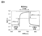
- the vehicle according to any one of the above preferably has a function of measuring the internal resistance by the current pause method.
- one aspect of the present invention includes a function of receiving first data regarding an internal state of a battery cell included in the assembled battery, which is transmitted from a vehicle including the assembled battery, and the first data and a first algorithm.
- a server device that has a function of calculating at least two or more estimated values using the estimated values and a function of transmitting the two or more estimated values to a vehicle.
- the first data preferably has sequential data regarding the internal state of the assembled battery.
- the sequential data preferably includes SOC-OCV characteristics.
- the sequential data include internal resistance.
- the internal resistance preferably includes a resistance component R1 with a fast response and a resistance component R2 with a slow response.
- any one of the above server devices it is preferable to have a function of predicting changes in resistance component R1 with fast response and resistance component R2 with slow response by LSTM.
- the present invention it is possible to estimate the internal state of a storage battery with high precision and in a short time. Note that even when the storage battery has an assembled battery, it is possible to estimate the internal state of the storage battery with high accuracy and in a short period of time.
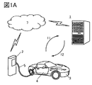
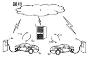
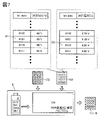
- FIG. 1A and 1B are conceptual diagrams of a storage battery management system that is one aspect of the present invention.
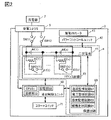
- FIG. 2 is a conceptual diagram of a vehicle that is one aspect of the present invention.
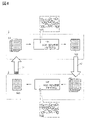
- FIG. 3 is a diagram illustrating a balancing process or a balancing circuit that is one aspect of the present invention.
- FIG. 4 is a diagram illustrating a processing method for SOC-OCV characteristic data, which is one aspect of the present invention.
- FIG. 5 is a diagram explaining a description method of SOC-OCV characteristic data, which is one aspect of the present invention.
- FIG. 6 is a diagram for explaining a processing method for FCC and internal resistance, which is one aspect of the present invention.
- FIG. 7 is a diagram illustrating a method for estimating internal resistance, which is one aspect of the present invention.
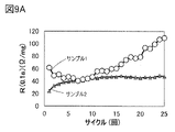
- FIG. 8 is a diagram showing an analysis method of current rest method measurement.
- 9A and 9B are examples of analysis results of current rest method measurement.
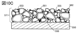
- 10A to 10C are diagrams illustrating a positive electrode that is one embodiment of the present invention.
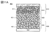
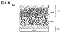
- 11A and 11B are diagrams illustrating an all-solid secondary battery that is one embodiment of the present invention.
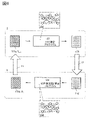
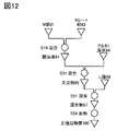
- FIG. 12 illustrates a method for manufacturing a positive electrode active material which is one embodiment of the present invention.
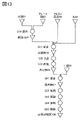
- FIG. 13 illustrates a method for manufacturing a positive electrode active material which is one embodiment of the present invention.
- FIG. 14 illustrates a method for manufacturing a secondary battery that is one embodiment of the present invention.
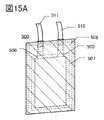
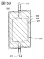
- 15A and 15B are diagrams illustrating the appearance and the like of a secondary battery that is one embodiment of the present invention.
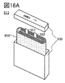
- 16A to 16C are diagrams illustrating the appearance and the like of a secondary battery that is one embodiment of the present invention.
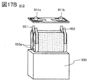
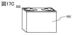
- 17A to 17C are diagrams illustrating the appearance and the like of a secondary battery that is one embodiment of the present invention.
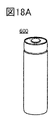
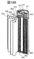
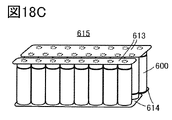
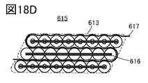
- 18A to 18D are diagrams illustrating the appearance and the like of a secondary battery that is one embodiment of the present invention.
- 19A to 19D are diagrams illustrating a vehicle that is one aspect of the present invention.
- the Miller index is used to describe crystal planes and crystal orientations. Individual planes indicating crystal planes are indicated using ( ). Crystal planes, crystal orientations, and space groups are indicated by a bar above the numbers in terms of crystallography. (minus sign) may be attached and expressed.
- the theoretical capacity of a positive electrode active material refers to the amount of electricity when all the lithium that can be inserted and detached included in the positive electrode active material is desorbed.
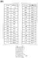
- LiCoO2 has a theoretical capacity of 274 mAh /g
- LiNiO2 has a theoretical capacity of 275 mAh /g
- LiMn2O4 has a theoretical capacity of 148 mAh/g.
- a storage battery refers to elements and devices in general that have a power storage function.
- Examples include secondary batteries such as lithium ion secondary batteries, lithium ion capacitors, and electric double layer capacitors.
- a power storage device includes a device for storing power obtained from a power generation facility such as a photovoltaic panel.
- electronic equipment refers to devices in general that have storage batteries, and electro-optical devices that have storage batteries, information terminal devices that have storage batteries, and the like are all electronic devices.
- a semiconductor device refers to an element, circuit, device, or the like that can function by utilizing semiconductor characteristics.
- semiconductor elements such as transistors and diodes are semiconductor devices.
- a circuit having a semiconductor element is a semiconductor device.
- a device including a circuit having a semiconductor element is a semiconductor device.
- FIGS 1A and 1B are conceptual diagrams of a storage battery management system.
- the storage battery management system includes a server device 1 and a vehicle 3 equipped with a storage battery pack (also referred to as a battery pack) 4 having a plurality of battery cells and means capable of transmitting and receiving data to and from the server device 1 .
- the server device 1 executes the estimation of the internal state of the battery cell, and the vehicle 3 can receive the execution result. That is, it is possible to cause the server device 1 to estimate the internal state of the battery cell, which has conventionally been performed on the vehicle 3 side.
- the server device 1 In order for the server device 1 to estimate the internal state of the battery cell, it is preferable to sequentially transmit data (including measured data or estimated data) related to the internal state of the battery cell from the vehicle 3 to the server device 1.
- Data transmitted sequentially may be referred to as serial data.
- the number of sequential data is large, it is recorded, that is, saved, in the server device 1, so that the storage section of the vehicle 3 is not burdened.
- two or more estimated values are transmitted from the server device 1 to the vehicle 3, and the vehicle 3 can select the optimum one from the two or more estimated values.
- the vehicle 3 does not perform estimation processing and selects the received estimated value.
- the estimated values may contain an error as the reason why the vehicle 3 made such a determination.
- Vehicle 3 can return to server device 1 a plurality of pieces of information about selected estimates, non-selected estimates, and errors.
- Such a system makes it possible to estimate the internal state of the storage battery with high accuracy and in a short period of time.
- the accuracy of the estimated value increases, which is preferable.
- the battery cells can measure the current, voltage, and temperature with the sensors, etc., of the vehicle 3. For example, the current of a battery cell can be measured as an integrated value by coulomb counting. Using these measured values, the internal state of the battery cell can be estimated. Estimating the internal state includes estimating SOC-OCV characteristics, estimating FCC, or estimating internal resistance (R). When estimating the SOC-OCV characteristics, the storage battery management system can be described as a storage battery SOC estimation system.
- the server device 1 can execute any one or more of the above internal state estimations.
- the estimation that has not been performed by the server device 1 may be performed by the vehicle 3 side.
- the estimation of the internal resistance (R), which requires less data, may be performed on the vehicle 3 side.
- FIG. 1B is a conceptual diagram when the storage battery management system is used in multiple vehicles.
- a plurality of vehicles may be the same model or different models.
- the server device 1 preferably functions as a cloud server, an AI (Artificial Intelligence) server, a GPU (Graphics Processing Unit) server, or the like. It is preferable that the server device 1 has an algorithm having a neural network, and the storage battery management system can be said to be a storage battery management system having artificial intelligence. It is preferable to have a CPU (Central Processing Unit) in addition to the GPU. Having a GPU or CPU enables fast computation.
- AI Artificial Intelligence
- GPU Graphics Processing Unit
- the storage battery pack 4 has a plurality of battery cells (so-called assembled batteries). Since the battery pack 4 has a plurality of battery cells, the amount of sequential data regarding the internal state is enormous. However, in one aspect of the present invention, the data can be recorded, that is, saved, in the server device 1 . Furthermore, since the server device 1 can execute the estimation process based on the data, it is preferable because the control unit or the storage unit on the vehicle 3 side is not burdened.
- the server device 1 and the vehicle 3 can transmit and receive data to and from each other via the communication network 7. That is, the server device 1 and the vehicle 3 each have communication means corresponding to the communication network 7 . Data transmission/reception can be performed at any timing, but should be performed while the vehicle 3 is being charged.
- the server device 1 may execute the estimation process and transmit/receive the estimated value during the charging period.
- the server device 1 and the vehicle 3 are not limited to one-to-one direct data communication.
- Data communication via, for example, may be employed.
- Wired communication or wireless communication may be used as the data communication method of the communication network 7 .
- wireless communication conforming to communication standards such as the fourth generation mobile communication system (4G) and the fifth generation mobile communication system (5G) can be used.
- the signal frequencies of wireless communication are, for example, submillimeter waves of 300 GHz to 3 THz, millimeter waves of 30 GHz to 300 GHz, microwaves of 3 GHz to 30 GHz, ultrashort waves of 300 MHz to 3 GHz, ultrashort waves of 30 MHz to 300 MHz, and short waves. Any of frequencies of 3 MHz to 30 MHz, medium waves of 300 kHz to 3 MHz, long waves of 30 kHz to 300 kHz, and very long waves of 3 kHz to 30 kHz can be used.
- the charger 2 may have the communication means compatible with the communication network 7 for data transmission/reception.
- data includes first data 11 sent from the vehicle 3 to the server device 1 and second data 12 sent from the server device 1 to the vehicle 3 .
- the first data 11 relates to the battery cells of the storage battery pack 4, and includes data measured by the sensor of the vehicle 3 or data estimated based on the measured data.
- the types of data regarding the storage battery pack 4 include FCC, internal resistance (R), and SOC-OCV characteristic data. Further, the data may include an accumulated charge amount.
- the accumulated charge amount of the storage battery pack 4 is one or both of the accumulated charge amount since it was installed in the vehicle 3 and the accumulated charge amount since the previous data transmission. There are two pieces of data indicating the amount of charge. Also, the first data 11 may contain error data.
- the second data 12 relates to the storage battery pack 4 and includes estimated data (estimated values).
- the types of estimated values for the storage battery pack 4 include FCC, internal resistance (R) value, SOC-OCV characteristic data, and accumulated charge amount.
- the estimated second data 12 have an estimated value of 2 or more.
- estimated SOC-OCV characteristic data A and estimated SOC-OCV characteristic data B can be selected by the vehicle 3 and used as an estimated value of the SOC-OCV of the storage battery pack 4, and the estimated value can be used for balancing as necessary. processing takes place.
- the first data 11 and the second data 12 can be transmitted and received between the server device 1 and the vehicle 3 without going through the charger 2, and the vehicle 3 preferably has communication means.
- a plurality of chargers (a first charger 2a and a second charger 2b) and a plurality of vehicles (a first vehicle 3a and a second vehicle 3b) sent to the server device 1 and a plurality of second data (second data 12a, and second data 12b).
- a plurality of first data and a plurality of second data can be exchanged with the server device 1 at the same time.
- the storage battery management system of the present invention can be used even when a plurality of vehicles are charged by a single charger.
- the storage battery management system of the present invention may be used after registering passengers.
- Vehicle information can also be registered when a passenger is registered, and vehicle information can be grasped in advance.
- the vehicle information includes initial value data, and types of the initial value data regarding the storage battery pack 4 include an internal resistance (R) value, SOC-OCV characteristic data, FCC, and the like.
- the timing for grasping the initial value includes aging before shipment of the storage battery pack or the vehicle.
- the vehicle 3 has a power receiving connector 5 and can be charged by inserting the power receiving connector 5 into the charger 2 .
- the charger 2 is equipped with a power receiving connector.
- the charger 2 is installed at home, a charging stand, a public parking lot, or the like.
- the vehicle 3 is configured as a plug-in hybrid vehicle, an EV vehicle, or an industrial vehicle such as an electric forklift, in which the storage battery pack 4 can be charged with electric power from the charger 2 .
- the storage battery pack 4 has storage batteries (secondary batteries) 41 .
- the secondary battery 41 has an assembled battery having a plurality of battery cells.
- the secondary battery 41 is referred to as a lithium ion secondary battery.
- a nickel-metal hydride battery may be used as the secondary battery 41 .
- the storage battery pack 4 may be referred to as a battery.
- the secondary battery 41 is electrically connected to the power receiving connector 5 via at least the first switch SW11 and the second switch SW12.
- the first switch SW11 is electrically connected to the negative terminal of the secondary battery 41 and the second switch SW12 is electrically connected to the positive terminal of the secondary battery 41 .
- a power control unit 42 is electrically connected to the secondary battery 41 , and a drive motor 43 is electrically connected to the power control unit 42 .
- the power control unit 42 has a function of converting the DC power supplied from the secondary battery 41 into AC power and outputting it to the drive motor 43 .
- Power control unit 42 has, for example, an inverter circuit capable of the above conversion.
- the power control unit 42 may also have a function of converting the AC power generated by the driving motor 43 into DC power and outputting the DC power to the secondary battery 41 when the vehicle 3 decelerates or stops. That is, the secondary battery 41 may store the regenerated electric power generated by the driving motor 43 .
- the assembled battery of the secondary battery 41 has a plurality of battery cells 44(1) to 44(n) (where n is a natural number of 2 or more), and the plurality of battery cells are connected in series.
- the cell balance state is determined during the charging period, and when the cell balance becomes impossible, the balancing process is performed.
- the balancing process is preferably completed during the charging period using SOC estimates for each battery cell.
- Estimation of SOC-OCV characteristics is important for balancing processing. It is preferable that the estimated values of the SOC-OCV characteristics sent from the server device 1 are in the form of a table. to complete the estimation of the SOC-OCV characteristics.
- Table creation for the vehicle 3 may be achieved by a method of selecting the optimum SOC-OCV characteristics (table) from a plurality of SOC-OCV characteristics (tables) transmitted from the server device 1 .
- the server device 1 may transmit to the vehicle 3 information on the stored state of health of the battery cells (FCC/FCC 0 , where FCC 0 is the initial full charge capacity).
- the health of the battery cells can be used to improve the accuracy of the table for the vehicle 3 .
- a balance circuit 45 is electrically connected to the secondary battery 41 shown in FIG. 2 for balancing processing.
- the balance circuit 45 has an active type and a passive type.
- the active type is a balance circuit that has the function of distributing and balancing the capacity among a plurality of battery cells connected in series.
- the passive type is a balance circuit that achieves balance by consuming the capacity of some battery cells in the assembled battery.
- FIG. 2 shows an example of using a passive balance circuit as the balance circuit 45, an active balance circuit may be used.
- the balance circuit 45 has at least a plurality of resistors 46(1) to 46(n) (where n is a natural number of 2 or more) corresponding to the plurality of battery cells 44(1) to 44(n).
- the balance circuit 45 also includes at least a plurality of switches SW21(1) to SW21(n) corresponding to the plurality of battery cells 44(1) to 44(n) and the plurality of resistors 46(1) to 46(n). ) (where n is a natural number of 2 or more).
- the balance circuit 45 a group having a resistor 46(1) and a switch SW21(1) is surrounded by a dotted line and denoted as circuit 47(1).
- the balance circuit 45 has a plurality of circuits 47(1) to 47(n) (where n is a natural number of 2 or more) according to the battery cells.
- the configuration of the circuit 47 is often different between the active type and the passive type, but the configuration having resistors and switches is often common. That is, the circuit 47 can be applied to an active balance circuit or a passive balance circuit.
- n be equal in the plurality of battery cells and the plurality of circuits described above, that is, the same number of cells be arranged, but it is also possible to share the circuit with, for example, battery cells of 2 to 15 cells. Cost can be reduced when circuits are shared.
- the balance circuit 45 has the function of matching the SOCs of the plurality of battery cells 44(1) to 44(n). This function can also be said to be a function of managing all battery cells so that they operate within the safe operating area.
- This function can also be said to be a function of managing all battery cells so that they operate within the safe operating area.
- the function of aligning the SOC using the four battery cells (the first battery cell 44(1) to the fourth battery cell 44(4)) shown in FIG. 3 or the importance of aligning the SOC will be described.
- the SOCs of the first battery cell 44(1) to the fourth battery cell 44(4) at a certain time are different from each other. This is equivalent to the fact that the SOC-OCV characteristics shown in FIG. 3 differ between the battery cells. In this state, the SOCs of the first battery cell 44(1) to the fourth battery cell 44(4) are different from each other.
- FIG. 3 shows a case where the SOC increases in the order of fourth battery cell 44(4)>first battery cell 44(1)>third battery cell 44(3)>second battery cell 44(2). .
- a first circuit 47(1) to a fourth circuit 47(4) are electrically connected to the first battery cell 44(1) to the fourth battery cell 44(4), respectively. Again, the first battery cell 44(1) to the fourth battery cell 44(4) are included in the secondary battery 41 shown in FIG. The first circuit 47(1) to the fourth circuit 47(4) are included in the balance circuit 45 shown in FIG.
- the capacity of the second battery cell 44(2) runs out the fastest. If the secondary battery 41 is continued to be used with the second battery cell 44(2) running out of capacity, the second battery cell 44(2) will be in an over-discharged state. On the other hand, if the secondary battery 41 is stopped when the second battery cell 44(2) has run out of capacity, the battery cells other than the second battery cell 44(2) have remaining capacity. A decrease in the dischargeable capacity of the secondary battery 41 occurs.
- balancing processing Aligning the SOC of each battery cell is referred to as balancing processing. Based on the situation shown in FIG. 3, it may be determined that the storage battery pack 4 requires a balancing process during the charging period or the like.
- the server apparatus 1 may estimate the SOC using measurable values (current and voltage) for each battery cell.
- measurable values current and voltage
- the SOC can be estimated using the SOC-OCV characteristic as shown in FIG.
- the measured voltage can correspond to the OCV of the SOC-OCV characteristics.
- the timing for executing the estimation of the SOC using the OCV is preferably the early stage of charging and the final stage of charging, which are circled by dotted lines in FIG. 3 .
- the initial stage of charging and the final stage of charging are periods in which the change in OCV is large but the change in SOC is small in the SOC-OCV characteristic. This period is preferable as the estimation timing because the influence of the OCV error on the SOC estimation is reduced.
- the timing for executing the SOC estimation may be the mid-charging period between the initial charging stage and the final charging stage shown in FIG.
- the mid-charging period is a period in which changes in OCV have a large effect on changes in SOC in the SOC-OCV characteristics.
- current integration coulomb counting, etc.
- For current integration it is necessary to grasp the amount of current that has flowed through each battery cell. The current amount is measured, the FCC of each battery cell is acquired, and the SOC can be estimated by combining techniques such as the Kalman filter.
- Machine learning should be performed on the vehicle 3 side, and it is possible to determine the optimum table for machine learning or to estimate the internal resistance at each SOC.
- the internal resistance in each SOC can be estimated from the current and voltage measured in the battery cells of the vehicle 3, for example.
- the internal resistance may be estimated by dividing it into a fast-response resistance component and a slow-response resistance component, as described in the method of estimating the internal resistance of the second embodiment. It is conceivable that the fast-response resistance component is related to the electron transfer resistance, and the slow-response resistance component is related to the ion diffusion resistance in the active material solid. Battery cells deteriorate due to repeated charging and discharging, but the state of deterioration differs depending on the type of battery cell and the installation environment, so the fast-response and slow-response resistance components may change differently .
- estimating separately the fast-response resistance component and the slow-response resistance component as described above can be said to be one means of indirectly knowing the state of deterioration inside the battery. Therefore, when data on internal resistance is used for estimation of SOC-OCV characteristics, SOC estimation, FCC estimation, etc., the increase in information reflecting the internal state of the battery improves the accuracy of various estimations, which is preferable.
- the server device 1 When estimating the internal resistance in the vehicle 3 , it is preferable to include the estimated data as sequential data to be transmitted to the server device 1 .
- the estimated data on the internal resistance is particularly useful in estimating the FCC in the server device 1 because it reflects the state of deterioration of each battery.
- the server device 1 can accumulate the estimated data of the plurality of vehicles 3 .
- the SOC estimation can be performed based on the OCV when performed at the early stage of charging and at the end of charging, and can be performed using current integration when performed during the middle period of charging. Since it is desirable to perform the SOC estimation at an early stage for the balancing process of each battery cell, it is preferable to perform the SOC estimation in the early stage of charging or in the middle of charging.
- the SOC estimation is preferably performed by the server device, but the SOC estimation may be performed by a vehicle control unit or the like.
- the SOC-OCV characteristic changes over time under the influence of deterioration due to repeated charging and discharging. Therefore, in order to obtain the current, that is, the latest, SOC-OCV characteristics with high accuracy, estimation based on a large amount of data is required, which may require computation time.
- the SOC-OCV characteristics of each battery cell vary. Others occur, for example, variations in deterioration rate, variations in impedance, or variations in self-discharge rate.
- variations in the deterioration rate include temperature dependence (the higher the temperature, the more deterioration progresses), voltage dependence (the higher the charging voltage, the more deterioration progresses, etc.), and depth-of-discharge dependence (the higher the discharge depth). deterioration progresses with increasing depth, etc.). Since these factors are intricately intertwined, it is difficult to estimate the SOC of each battery cell, and considering the above dependency, the estimation of the SOC requires a huge amount of calculations.
- the server device 1 it is preferable to cause the server device 1 to execute arithmetic processing related to estimation of the latest SOC-OCV characteristics.
- the second circuit 47(2) After the vehicle 3 acquires the latest SOC-OCV characteristics, in order to match the SOC of the second battery cell 44(2) with the SOC of the other battery cells, the second circuit 47(2) The switches of the first circuit 47(1), the third circuit 47(3), and the fourth circuit 47(4) corresponding to the battery cells other than the battery cells are turned on. Then, the battery cells other than the second battery cell 44(2) are discharged, and the SOC of the battery cells other than the second battery cell 44(2) is aligned with the SOC of the second battery cell 44(2). be able to. Discharge using the resistance of the circuit 47 is referred to as resistance discharge.
- the SOC When the SOC is aligned by such a method, it can be typically achieved by a balance circuit 45 having a simple circuit configuration such as switches and resistors, but energy is wasted. Furthermore, heat is generated with energy consumption. When energy consumption is involved, it is referred to as a passive balance circuit or passive balancing process.
- the first circuit 47 ( 1) to the third circuit 47(3) are turned off, and the switch (not shown) between the negative terminal of the battery cell 44(3) and the positive terminal of the battery cell 44(4) is turned off.
- the switch of the fourth circuit 47(4) connected to the negative terminal of the battery cell 44(3) is turned on to start charging.
- the fourth battery cell 44(4) can be bypassed for charging, and the SOC of the battery cells other than the fourth battery cell 44(4) is increased to reach the SOC of the fourth battery cell 44(4). can be aligned.
- Such a method requires charging by bypassing the fourth battery cell 44(4). Therefore, compared to the case where the second battery cell 44 ( 2 ) is aligned, the number of switches in the secondary battery 41 and the balance circuit 45 increases, and the circuit configuration becomes complicated. Furthermore, heat is generated with energy consumption. That is, it corresponds to a passive balance circuit or balancing process.
- the balance circuit 45 When the balance circuit 45 is operated in this way, the current SOC value of each battery cell is used as a basis, so by estimating the SOC by the server device 1, it is possible to obtain a highly accurate SOC, which is preferable. In order to operate the balance circuit 45, it is preferable to start the SOC estimation in the server device 1 at an early timing during the charging period.
- the balancing process be completed in a short time, just as it is required to shorten the time required for charging, such as the rapid charging mode.
- AI via an algorithm can be used for estimation in the server device 1.
- AI via algorithms can be used for estimation in vehicle 3.
- the storage battery pack 4 acquires data regarding the internal state of the battery cell 44 at regular intervals, and the data is sent from the storage battery pack 4 using the communication network 7 or the like.
- the data is sent to the server device 1, and further, the server device 1 executes an estimation process related to the internal state, and a plurality of execution results are created and stored.
- the state is selected from the data stored in the server device 1 or the storage unit 52 .
- Communication between the storage battery pack 4 and the server device 1 can be performed via the vehicle control unit 50, but the storage battery pack 4 may be configured to have a communication function.
- data on SOC and the like can be obtained with high accuracy and in a short time.
- Arithmetic processing related to SOC estimation executed by the server device 1 can be completed in a short time, and the server device 1 can also increase the frequency of computational processing.
- the arithmetic processing in the server device 1 can be executed in parallel while the vehicle 3 is being charged, the balancing processing can be completed in a short time.
- the data and estimation results related to the SOC and the like stored in the server device 1 are versatile, they can be provided to a plurality of storage battery packs 4 as well.
- the storage battery pack 4 can obtain a highly accurately estimated SOC and the like, and the storage battery pack 4 does not require a new control unit or the like, and the SOC can be aligned most efficiently. Wasteful energy consumption associated with the balancing process is suppressed, and the capacity of the storage battery pack 4 can be maximized.
- data is transmitted and received between the vehicle 3 and the server device 1 as shown in FIGS. 1A and 1B.
- Data transmission/reception is preferably performed while the vehicle 3 is stopped and connected to the charger 2 .
- the battery pack 4 of the vehicle 3 starts charging.
- the charging period during which the power receiving connector 5 is connected to the charger 2 can be divided into initial and middle CC (Constant Current) charging periods and final CV (Constant Voltage) charging periods. .
- the remaining capacity until full charge may be calculated from each battery cell, and the battery cell that takes the longest time to be fully charged may be specified.
- the timing at which discharge in the circuit 47 is started that is, the order of discharge in the circuit 47 may be determined.
- the SOC-OCV characteristic table is created by the server device 1 during the CC charging period, but after charging is completed, the table can be corrected by the GPU mounted on the vehicle if necessary.
- the vehicle 3 may integrate the SOC data of each battery cell 44 to create a fuel gauge table for passengers (users).
- the vehicle control unit 50 has at least a CPU 51, a storage unit 52, and a communication unit 53, and operates with power supplied from the secondary battery 41 or a separately provided storage battery.
- the vehicle control unit 50 is sometimes called a vehicle control unit.
- the vehicle control unit 50 is a control device for determining the state of the vehicle and maintaining the optimum state. can be used to control the entire vehicle.
- the vehicle control unit 50 can select data related to the SOC, etc., stored in the server device 1 .
- the vehicle control unit 50 has at least a CPU 51, and the CPU 51 performs calculations for selecting data relating to the optimum SOC, etc., which is closest to the current battery cell state, from the data stored in the server device 1 or the storage unit 52. Processing can be performed.
- the vehicle control unit 50 can have a CPU and a GPU capable of arithmetic processing.
- the vehicle control unit 50 has a storage section 52, and the storage section 52 has RAM, ROM, and the like.
- the storage unit 52 can record SOC-OCV characteristic data of the plurality of battery cells 44 . Further, the storage unit 52 can record data related to SOC and the like selected from the server device 1 .
- the storage unit 52 can also store programs for controlling the storage battery pack 4 and the like. By executing one of the programs, the CPU 51 can select, from the data stored in the server device 1 or the storage unit 52, the data regarding the SOC, etc., which is closest to the current state for each of the plurality of battery cells 44. It is possible.
- the vehicle control unit 50 has a communication section 53 and can transmit and receive data to and from the server device 1 .
- the storage battery pack 4 has a protection circuit 60 .
- a current monitoring circuit 61 included in the protection circuit 60 may have a sensor function for measuring charge/discharge current as a measurement value obtained from the secondary battery 41 . By measuring the charging/discharging current using the current monitoring circuit 61, coulomb counting of the battery cell can be performed, and data regarding the SOC and the like can be obtained.
- the voltage monitoring circuit 62 of the protection circuit 60 may have a sensor function capable of measuring the terminal voltage of each battery cell 44 as a measured value obtained from the secondary battery 41 or the like.
- the temperature monitoring circuit 63 included in the protection circuit 60 may have a sensor function capable of measuring the temperature of each battery cell 44 as a measured value obtained from the secondary battery 41 or the like.
- a path cutoff circuit 64 included in the protection circuit 60 can cut off the charging/discharging current path to the secondary battery 41 or the like.
- the vehicle control unit 50 can acquire the measured value obtained from the protection circuit 60 as a parameter. It is possible to forcibly stop discharging or charging a battery cell determined to be in an over-discharged state or an over-charged state based on the obtained measurement value. The vehicle control unit 50 can determine whether to forcibly stop.
- the vehicle control unit 50 can control the balance circuit 45 according to the data regarding the selected SOC and the like. Specifically, the vehicle control unit 50 can control whether the switches SW21(1) to SW21(n) of the balance circuit 45 are turned on or off.
- a start switch 71 is electrically connected to the vehicle control unit 50 .
- the vehicle control unit 50 can switch between an activated state and a stopped state of the vehicle 3 according to the operation of the start switch 71 by the passenger.
- the vehicle control unit 50 can switch the vehicle 3 between a start state and a stop state according to the state of charge of the secondary battery 41 , thereby enabling the operation of the start switch 71 .
- data relating to the SOC and the like of each battery cell is sequentially acquired from the storage battery pack 4 at regular intervals, and the acquired data is stored in the server device 1 using the communication network 7 or the like.
- An estimation result can be calculated by causing the server device 1 to perform calculations related to SOC estimation.
- the data on the SOC, etc. that is closest to the current state of the battery cell 44 can be selected from the data stored in the server device 1 or the storage unit 52. Therefore, the data on the SOC, etc. can be obtained with high accuracy and in a short time. can be obtained with
- the data and estimation results related to the SOC and the like stored in the server device are versatile, they can be provided to the storage battery packs 4 possessed by a plurality of vehicles 3.
- the storage battery pack 4 can obtain a highly accurately estimated SOC and the like, and the process of aligning the SOC most efficiently by a balance circuit or the like can be performed.
- the storage battery pack 4 that has been subjected to the balancing process has a configuration that can utilize the optimum FCC. Such a configuration is sometimes described as marginal utilization of the battery because it allows the battery to be utilized as much as possible.
- the plurality of battery cells 44 of the storage battery pack 4 can be used to the limit.
- FIG. 4 shows the generation of SOC-OCV characteristic data in the server device 1 and the SOC-OCV characteristic data in the vehicle 3 side, for example, the vehicle control unit 50, with respect to the SOC-OCV characteristic data possessed by the first data 11 and the second data 12.
- FIG. 4 is a diagram for explaining selection of characteristic data;
- the server device 1 has a first algorithm 121.
- the first algorithm 121 has a function of creating first SOC-OCV characteristic data 162 using at least part of the first data 11 as input data.
- the first SOC-OCV characteristic data 162 has estimated values.
- First algorithm 121 preferably comprises a first neural network 131 .
- the server device 1 also has a function of transmitting the first SOC-OCV characteristic data 162 to the vehicle 3 side as part of the second data 12 .
- the transmitted first SOC-OCV characteristic data 162 is added as part of the SOC-OCV characteristic data list 161 of the vehicle 3 .
- the vehicle 3 side has a second algorithm 122.
- the second algorithm 122 is preferably recorded in the storage section 52 of the vehicle control unit 50 or the like.
- the second algorithm 122 uses the SOC-OCV characteristic data list 161 and the voltage value, current value, battery cell temperature, capacity value, etc. of the storage battery pack 4 collected in the vehicle control unit 50 as input values to generate a plurality of It has a function of selecting the second SOC-OCV characteristic data 163 from the SOC-OCV characteristic data list 161 .
- As the second SOC-OCV characteristic data 163, the one closest to the state of the battery cell 44 of the vehicle 3 at the time of selection is selected.
- the term "closest" refers to the smallest difference from the entire range of the SOC-OCV characteristics of the battery cell.
- the second algorithm 122 Since it is difficult to actually measure the entire range of SOC-OCV characteristics of battery cells, the second algorithm 122 needs to select the second SOC-OCV characteristic data 163 based on limited input data. . Therefore, the second algorithm 122 preferably has a second neural network 132 . Having the second neural network 132, the second algorithm 122 can select the second SOC-OCV characteristic data 163 that is closest to the state of the battery cell using limited input data. Vehicle 3 also has a function of transmitting second SOC-OCV characteristic data 163 to server device 1 as part of first data 11 . Note that the second algorithm 122 may be installed in an electronic device such as a smart phone owned by a passenger of the vehicle 3 .
- Examples of the first neural network 131 include FFNN (Feedforward Neural Network), CNN (Convolutional Neural Network), RNN (Recurrent Neural Network) and LSTM (Long Short- Term Memory, long/short-term memory unit) can be used.
- FFNN Field Neural Network
- CNN Convolutional Neural Network
- RNN Recurrent Neural Network
- LSTM Long Short- Term Memory, long/short-term memory unit
- any one of FFNN, CNN, RNN and LSTM can be used as the second neural network 132 .
- the second neural network 132 may select the second SOC-OCV characteristic data 163 from the SOC-OCV characteristic data list 161 as a classification problem using a decision tree.
- FIG. 5 shows the description system of SOC data, showing the relationship between bit data and corresponding SOC [%]. Also, as a description method of OCV data, the relationship between bit data and corresponding voltage [V] is shown. For example, when the specific bit data in the SOC data is 0011, the corresponding SOC is 40% and the corresponding voltage in the OCV data is 3.300V.
- the SOC data is data paired with the SOC data, and is assigned as the OCV data so as to correspond to each SOC data.
- FIG. 5 shows an example of data description method of the first SOC-OCV characteristic data 162, in which data intervals are assigned so as to become finer in the range where the SOC is close to 100%.
- an overcharged state where the SOC exceeds 100% may lead to a decrease in the safety of the battery cell and a decrease in battery life. More is desirable.
- Assignment of bit data can be performed by the server device 1 .
- the SOC range in which the SOC is close to 100% is preferably 90% or more and 110% or less, more preferably 95% or more and 105% or less. , is preferably doubled or more.
- FIG. 5 an example of 4 bits is shown for explanation, but the data is not limited to this, and data is described with a bit number larger than 4 bits, such as 8 bits, 16 bits, 32 bits, 64 bits, etc. may When using a large number of bits, it may not be necessary to allocate more bit data for the partial range of SOC shown above. This is because when the number of bits assigned to the SOC-OCV characteristic data is large, not only a partial range of SOC but also the entire range of SOC can be described in detail.
- State A to State D representing the state of the battery cells are represented as surplus bit data. It shows an example of assignment. State A to State D representing the states of the battery cells can be assigned as data indicating, for example, a dangerous state such as an internal short circuit.
- the data processing function related to the SOC-OCV characteristic data of the storage battery management system of one aspect of the present invention makes it possible to improve the accuracy of battery cell estimation.
- the weight reduction (reduction of data amount) of the SOC-OCV characteristic data performed by the server device 1 and the adaptation to neural network processing make it possible to reduce the power consumption of the control unit of the vehicle 3 .
- FIG. 6 shows that, with respect to the FCC of the first data 11 and the internal resistance (R) of the second data, the server device 1 estimates the FCC, and the vehicle 3 side estimates the internal resistance. For example. In this manner, in addition to the estimation performed by the server device 1, the estimation performed by the vehicle 3 may be performed.
- the functional configuration of the storage battery management system for estimating FCC and internal resistance will be described.
- the server device 1 has a third algorithm 123 .
- the third algorithm 123 is a function of estimating the FCC 172 using the internal resistance 171a calculated based on the battery cell (R data of one cycle before estimated in the battery cell and denoted as Rn -1 ) as input data.
- have Third algorithm 123 preferably comprises a third neural network 133 .
- the server device 1 also has a function of transmitting the FCC 172 to the vehicle 3 as part of the second data 12 .
- the vehicle 3 has a fourth algorithm 124 .
- the fourth algorithm 124 uses the FCC 172, the second SOC-OCV characteristic data 163, and the voltage value, current value, and capacity value of the battery cell as input data, and uses the internal resistance 171b of the battery cell (R data and is denoted as Rn ).
- the fourth algorithm 124 preferably has a fourth neural network 134 .
- the vehicle 3 also has a function of transmitting the internal resistance 171b (R n ) to the server device 1 as part of the first data 11 .
- any one of FFNN, CNN, RNN and LSTM can be used as the third neural network 133 .
- any one of FFNN, CNN, RNN (and LSTM) can be used as the fourth neural network 134.
- FIG. 7 shows the function of the fourth algorithm 124 that the vehicle 3 has, and the first SOC-OCV characteristic data 162, the FCC 172, and the internal measurement value of the battery cell 44 are input to the fourth algorithm 124. By doing so, the internal resistance 171 is estimated.
- the internal resistance may be estimated by the server device 1 .
- the internal measurement values of each battery cell are the voltage value (V) 31 and current value (I) 32 measured from the battery cell, and the capacity value (Q) 33 and temperature (T) measured by a coulomb counter or the like. 34.
- the FCC and internal resistance estimation functions of the storage battery management system of one aspect of the present invention make it possible to increase the accuracy of estimating the FCC and internal resistance of the battery cell.
- the lightened (reduced amount of data) SOC-OCV characteristic data for estimating the internal resistance it is suitable for performing neural network processing, and the power consumption of the control unit of the vehicle 3 can be reduced. becomes.
- the internal resistance 171 may be estimated from the measurement results by the current pause method described in FIGS.
- the fourth algorithm 124 may have a function of estimating the internal resistance by the current pause method described below.
- the current rest method is a method in CC charging in which a rest period during which no charging is performed is provided for a certain period of time, changes in battery cell voltage during the rest period are analyzed, and the internal resistance is estimated.
- a method of estimating the internal resistance by providing an idle period during CC discharge for a certain period of time during which no discharge is performed, analyzing the change in the voltage of the battery cell during the idle period.
- the rest period is preferably from 1 second to 10 minutes, more preferably from 5 seconds to 5 minutes, and more preferably from 10 seconds to 3 minutes.
- FIG. 8 is a diagram for explaining the analysis method of the current pause method.
- FIG. 8 shows an example of the current pausing method in CC discharging, the present invention is not limited to this, and the current pausing method may be used in CC charging.
- ⁇ V (0.1 s) be the difference between the battery voltage immediately before the rest period and the battery voltage 0.1 seconds after the start of the rest period.
- the difference between the battery voltage 0.1 seconds after the start of the rest period and 120 seconds after the start of the rest period (battery voltage at the end of the rest period) is defined as ⁇ V (0.1 s to 120 s).
- the value obtained by dividing ⁇ V (0.1 s) by the current value of constant current discharge is defined as the resistance component R (0.1 s) with a fast response, and ⁇ V (0.1 s to 120 s) is the current value of constant current discharge.
- the fast-response resistance component R (0.1 s) is mainly derived from electrical resistance (electron conduction resistance), and the slow-response resistance component R (0.1 s to 120 s) is mainly derived from the active material particles. It is considered to be derived from Li diffusion resistance.
- FIG. 9A shows the transition of the resistance component R (0.1 s) with a fast response.
- FIG. 9B shows transitions of the fast-response resistance component R (0.1 s) and the slow-response resistance component R (0.1 s to 120 s) for sample 1. As shown in FIG.
- the fast-response resistance component R (0.1 s) of sample 1 tends to increase after decreasing, and the fast-response resistance component R (0.1 s) of sample 2 only increases. Change. In this way, the change in resistance component R (0.1 s), which responds quickly, does not tend to be uniform, and may differ depending on the battery.
- the slow-response resistance component R (0.1 s to 120 s) changes more than the fast-response resistance component R (0.1 s).
- the slow-response resistance component R (0.1 s to 120 s) sharply increased from around the 20th cycle, and remained almost constant after the 27th cycle. In this way, the fast-response resistance component R (0.1 s) and the slow-response resistance component R (0.1 s to 120 s) may have different changing tendencies.
- a neural network such as LSTM is used as time-series data estimation for each of the fast-response resistance component R (0.1 s) and the slow-response resistance component R (0.1 s to 120 s). It is preferable to have a function of predicting future changes in internal resistance for each resistance component.
- the server device 1 may have the above prediction function.
- the server device 1 internally performs internal If it has a function of predicting future changes in resistance for each resistance component, it is possible to accumulate data corresponding to the secondary batteries 41 of a plurality of vehicles 3 and improve the prediction accuracy of the neural network. Therefore, it is preferable.
- the vehicle has a plurality of battery cells 44 like the vehicle 3 shown in the examples so far, it is preferable to measure, estimate, and predict the internal resistance for each battery cell. Since the plurality of battery cells 44 have variations in manufacturing characteristics of the battery cells 44, and the environmental temperature may change depending on the mounting position of the battery cells 44 in the secondary battery 41, each of the plurality of battery cells 44 By measuring, estimating, and predicting the internal resistance, a storage battery control system capable of more accurate control can be realized.
- the voltage values (V) 31 and the current values (I) 32 of the plurality of battery cells 44 are measured by a plurality of It is preferable to provide an A/D converter for each of the voltage value (V) 31 and the current value (I) 32 of the battery cell 44 .
- the voltage values (V) 31 of the plurality of battery cells 44 may be acquired using the change in the current value (I) 32 as a trigger.
- the vehicle 3 may have third SOC-OCV characteristic data in addition to the SOC-OCV characteristic data list 161 and the second SOC-OCV characteristic data 163 .
- the third SOC-OCV characteristic data can be created based on the second SOC-OCV characteristic data 163 and the estimated load of the vehicle 3. An average current consumption value of the battery cells can be used as the estimated load.
- the corresponding voltage in the range where the SOC is low in the OCV data is set higher according to the estimated load of the vehicle 3 than in the second SOC-OCV characteristic data 163. .
- the OCV at which the SOC is 0% in the third SOC-OCV characteristic data is higher than the OCV at which the SOC is 0% in the second SOC-OCV characteristic data 163 .
- FIG. 10A shows an example of a cross-sectional view of the positive electrode.
- the positive electrode has a positive electrode active material layer 571 over a positive electrode current collector 550 .
- the positive electrode active material layer 571 includes a positive electrode active material 561 , a positive electrode active material 562 , a binder (binding agent) 555 , a conductive aid 553 , a conductive aid 554 , and an electrolyte 556 .
- the positive electrode active material 561 has a larger average particle size than the positive electrode active material 562 .
- the positive electrode active material 561 and/or the positive electrode active material 562 are sometimes referred to as positive electrode active material particles, but take various shapes other than particles.
- the positive electrode active material 561 and/or the positive electrode active material 562 may be primary particles having a plurality of crystallites, or secondary particles formed by aggregation of primary particles.
- Carrier ions can be lithium ions, sodium ions, potassium ions, calcium ions, strontium ions, barium ions, beryllium ions, or magnesium ions.
- Materials capable of intercalating and deintercalating lithium ions include lithium composite oxides having an olivine-type crystal structure, a layered rock salt-type crystal structure, or a spinel-type crystal structure.
- M may be one or more selected from Fe, Mn, Ni, and Co.
- NiCoMn system (also referred to as NCM) represented by LiNixCoyMnzO2 ( x >0, y>0, 0.8 ⁇ x+ y + z ⁇ 1.2) as a composite oxide containing Ni, Mn and Co
- 0.1x ⁇ y ⁇ 8x and 0.1x ⁇ z ⁇ 8x it is preferable to satisfy 0.1x ⁇ y ⁇ 8x and 0.1x ⁇ z ⁇ 8x.
- NiCoMn NiCoMn system
- oxides such as V 2 O 5 and Nb 2 O 5 are being studied as positive electrode materials.
- spinel type crystal structure lithium composite oxides include lithium manganese spinel (LiMn 2 O 4 ) and the like.
- Lithium composite oxide contains at least one element selected from the group consisting of nickel, chromium, aluminum, iron, magnesium, molybdenum, zinc, zirconium, indium, gallium, copper, titanium, niobium, silicon, fluorine and phosphorus. It may be A lithium composite oxide containing Ni, Mn and Co containing aluminum is sometimes referred to as NCMA. A lithium composite oxide containing Ni and Co containing aluminum is sometimes referred to as NCA.
- the average particle diameter of the positive electrode active material 561 is 1 ⁇ m or more and 50 ⁇ m or less, preferably 5 ⁇ m or more and 20 ⁇ m or less.
- the positive electrode active material 561 can be considered as secondary particles, and the average particle size of the secondary particles is 1 ⁇ m or more and 50 ⁇ m or less, preferably 5 ⁇ m or more and 20 ⁇ m or less. good.
- a positive electrode active material 562 having a different particle size may be added in order to increase the packing density of the active material.
- Different particle sizes refer to different maximum values of the average particle size.
- the positive electrode active material 562 has a maximum average particle diameter smaller than that of the positive electrode active material 561 .
- the maximum value of the average particle size of the positive electrode active material 562 is preferably 1/6 or more and 1/10 or less of the maximum value of the average particle size of the positive electrode active material 561 .
- the charging density can be increased without the positive electrode active material 562.
- manufacturing steps can be reduced, and further cost reduction can be achieved.
- the positive electrode active material 561 and/or the positive electrode active material 562 may have grain boundaries. Grain boundaries may be located between crystallites.
- FIG. 10A shows a surface layer portion 572 of the positive electrode active material 561 .
- the surface layer portion 572 exists within 50 nm, more preferably within 35 nm, still more preferably within 20 nm, and most preferably within 10 nm from the surface of the positive electrode active material 561 toward the inside in a cross-sectional view.
- the additive element should be unevenly distributed in the surface layer. Uneven distribution indicates that the additive element exists non-uniformly or unevenly, and the concentration of the additive element is higher in one region than in another region. Uneven distribution may be described as segregation or precipitation.
- additive elements are preferably unevenly distributed in the surface layer portion of the positive electrode active material.
- the uneven distribution of the additive element can be confirmed by the presence of the additive element at a higher concentration in the surface layer portion than in the inside of the positive electrode active material. Since the additive element is present at least in the surface layer portion, it is possible to prevent structural deterioration during charging and discharging, so that the positive electrode active material is difficult to deteriorate.
- a structure in which the surface layer portion 572 is provided inside the active material is sometimes referred to as a core-shell structure.
- a core-shell structure can also be applied to the positive electrode active material 562 .
- the binder 555 is provided to prevent the positive electrode active material 561 or the conductive aid 553 from slipping off the positive electrode current collector 550 .
- the binder 555 also serves to bind the positive electrode active material 561 and the conductive aid 553 together. Therefore, some binders 555 are positioned so as to be in contact with the positive electrode current collector 550 , some are positioned between the positive electrode active material 561 and the conductive aid 553 , and some are positioned so as to be entangled with the conductive aid 553 .
- the binder 555 has resin, which is a polymer material. If a large amount of binder is included, the proportion of the positive electrode active material 561 in the positive electrode active material layer 571 may decrease. Since a decrease in the ratio of the positive electrode active material 561 leads to a decrease in the discharge capacity of the secondary battery, the amount of the binder 555 mixed is minimized.
- the positive electrode active material 561 is a composite oxide, it may have high resistance. Then, it becomes difficult to collect current from the positive electrode active material 561 to the positive electrode current collector 550 . Therefore, the conductive aid 553 and/or the conductive aid 554 are used to form current paths between the positive electrode active material 561 and the positive electrode current collector 550, current paths between the plurality of positive electrode active materials 561, current paths between the plurality of positive electrode active materials and the positive electrode collector. It has a function of assisting a current path with the electric body 550 .
- the conductive aid 553 and/or the conductive aid 554 are made of a material having a lower resistance than the positive electrode active material 561, and the conductive aid 553 and/or the conductive aid 554 are used as the positive electrode current collector. Some are located in contact with the positive electrode active material 550 and some are located in gaps between the positive electrode active materials 561 .
- the conductive aid 553 is also called a conductive agent or a conductive material because of its role, and a carbon material or a metal material is used.
- Carbon black (furnace black, acetylene black, graphite, etc.) is available as a carbon material used for the conductive aid 553 .
- Carbon black has a particle size smaller than that of the positive electrode active material 561 .
- Carbon nanotubes (CNT) and VGCF (registered trademark) are available as fibrous carbon materials used for the conductive aid 554 .
- a sheet-like carbon material used for the conductive aid 554 includes multilayer graphene.
- FIG. 10A is a cross section of the positive electrode, and the sheet-like carbon material may look like threads.
- the particulate conductive aid 553 can enter the gaps of the positive electrode active material 561 and easily aggregate. Therefore, the particulate conductive aid 553 can assist a conductive path between positive electrode active materials arranged close to each other (between adjacent positive electrode active materials).
- the fibrous or sheet-like conductive aid 554 also has bent regions, which are larger than the positive electrode active material 561 . Therefore, the fibrous or sheet-like conductive aid 554 can assist the conductive path between the positive electrode active materials arranged apart from each other, in addition to the adjacent positive electrode active materials. It is preferable to mix a particulate, fibrous, or sheet-like conductive agent.
- the weight of carbon black in the slurry is 1.5 times or more and 20 times or less, preferably 2 times or more that of graphene.
- the weight should be 9.5 times or less.
- the carbon black does not aggregate and is easily dispersed.
- the electrode density can be made higher than when only carbon black is used as the conductive aid. By increasing the electrode density, the capacity per unit weight can be increased. Specifically, the density of the positive electrode active material layer can be higher than 3.5 g/cc.
- a positive electrode using a mixture of graphene and carbon black as a conductive agent can respond to faster charging than a positive electrode using only graphene as a conductive agent. Furthermore, it is preferable to set the mixing ratio of graphene and carbon black within the above range.
- laminated secondary battery As a secondary battery installed in a vehicle.
- the number of laminated secondary batteries is increased to extend the mileage of the vehicle.
- the laminate battery increases the weight of the vehicle, thus increasing the energy required to move the vehicle. Without increasing the number of laminated secondary batteries and without changing the total weight of the vehicle, the driving distance can be extended.
- the secondary battery mounted on the vehicle has a high capacity, it requires power for charging, so it is desirable to finish charging in a short time.
- the secondary battery mounted on the vehicle has a high capacity, it is preferable because rapid charging is possible in so-called regenerative charging, in which power is temporarily generated when the vehicle brakes are applied and the amount of power generated is charged.
- the electrolyte 556 preferably has a solvent and a metal salt that serves as carrier ions.
- Preferred electrolyte solvents are aprotic organic solvents such as ethylene carbonate (EC), propylene carbonate (PC), butylene carbonate, chloroethylene carbonate, vinylene carbonate, ⁇ -butyrolactone, ⁇ -valerolactone, dimethyl carbonate ( DMC), diethyl carbonate (DEC), ethyl methyl carbonate (EMC), methyl formate, methyl acetate, ethyl acetate, methyl propionate, ethyl propionate, propyl propionate, methyl butyrate, 1,3-dioxane, 1,4- Dioxane, dimethoxyethane (DME), dimethyl sulfoxide, diethyl ether, methyl diglyme, acetonitrile, benzonitrile, tetrahydrofuran, sul
- Ionic liquids consist of cations and anions, including organic cations and anions.
- Organic cations used in the electrolyte include aliphatic onium cations such as quaternary ammonium cations, tertiary sulfonium cations and quaternary phosphonium cations, and aromatic cations such as imidazolium cations and pyridinium cations.
- anions used in the electrolyte include monovalent amide anions, monovalent methide anions, fluorosulfonate anions, perfluoroalkylsulfonate anions, tetrafluoroborate anions, perfluoroalkylborate anions, hexafluorophosphate anions, Alternatively, perfluoroalkyl phosphate anions and the like can be mentioned.
- Examples of salts dissolved in the above solvents include LiPF 6 , LiClO 4 , LiAsF 6 , LiBF 4 , LiAlCl 4 , LiSCN, LiBr, LiI, Li 2 SO 4 , Li 2 B 10 Cl 10 , Li 2 B 12 Cl12 , LiCF3SO3 , LiC4F9SO3 , LiC ( CF3SO2 ) 3 , LiC ( C2F5SO2 ) 3 , LiN ( CF3SO2 ) 2 , LiN ( C4F9 SO 2 )(CF 3 SO 2 ), LiN(C 2 F 5 SO 2 ) 2 or the like can be used alone, or two or more thereof can be used in any combination and ratio.
- the electrolyte used in the secondary battery it is preferable to use a highly purified electrolytic solution containing only a small amount of particulate matter and elements other than the constituent elements of the electrolyte (hereinafter also simply referred to as "impurities").
- impurities a highly purified electrolytic solution containing only a small amount of particulate matter and elements other than the constituent elements of the electrolyte.
- the weight ratio of impurities to the electrolyte is preferably 1% or less, preferably 0.1% or less, and more preferably 0.01% or less.
- the electrolyte includes vinylene carbonate, propane sultone (PS), tert-butylbenzene (TBB), fluoroethylene carbonate (FEC), lithium bis(oxalate)borate (LiBOB), and dinitrile compounds such as succinonitrile and adiponitrile.
- Additives may be added.
- the concentration of the material to be added may be, for example, 0.1 wt % or more and 5 wt % or less with respect to the entire solvent.
- VC or LiBOB are particularly preferred because they tend to form good coatings.
- a solution containing a solvent and a salt that serves as carrier ions is sometimes called an electrolytic solution.
- a polymer gel electrolyte in which a polymer is swollen with an electrolytic solution may be used.
- silicone gel acrylic gel, acrylonitrile gel, polyethylene oxide gel, polypropylene oxide gel, fluorine polymer gel, etc. can be used.
- polymers having a polyalkylene oxide structure such as polyethylene oxide (PEO), PVDF, polyacrylonitrile, etc., and copolymers containing them can be used.
- PVDF-HFP which is a copolymer of PVDF and hexafluoropropylene (HFP)
- the polymer formed may also have a porous geometry.
- a solid electrolyte containing an inorganic material can also be used as the electrolyte.
- sulfide-based solid electrolytes, oxide-based solid electrolytes, halide-based solid electrolytes, and the like can be used.
- a solid electrolyte having a polymer material such as PEO (polyethylene oxide) can be used.
- Sulfide - based solid electrolytes include thiolysicone - based ( Li10GeP2S12 , Li3.25Ge0.25P0.75S4 , etc.), sulfide glass ( 70Li2S , 30P2S5 , 30Li2 S.26B2S3.44LiI , 63Li2S.36SiS2.1Li3PO4 , 57Li2S.38SiS2.5Li4SiO4 , 50Li2S.50GeS2 , etc. ) , sulfide crystallized glass ( Li7 P 3 S 11 , Li 3.25 P 0.95 S 4 etc.).
- a sulfide-based solid electrolyte has advantages such as being a material with high conductivity, being able to be synthesized at a low temperature, and being relatively soft so that a conductive path is easily maintained even after charging and discharging.
- oxide-based solid electrolytes examples include materials having a perovskite-type crystal structure (La2 /3- xLi3xTiO3 , etc.), materials having a NASICON-type crystal structure (Li1- xAlxTi2- x ( PO4 ) 3 , etc.), materials having a garnet - type crystal structure ( Li7La3Zr2O12 , etc.), materials having a LISICON - type crystal structure ( Li14ZnGe4O16 , etc.) , LLZO ( Li7La3Zr2O 12 ), oxide glass ( Li3PO4 - Li4SiO4 , 50Li4SiO4 , 50Li3BO3 , etc.), oxide crystallized glass ( Li1.07Al0.69Ti1.46 ( PO4 ) 3 , Li 1.5 Al 0.5 Ge 1.5 (PO 4 ) 3 etc.). Oxide-based solid electrolytes have the advantage of being stable in the atmosphere.
- Halide-based solid electrolytes include LiAlCl 4 , Li 3 InBr 6 , LiF, LiCl, LiBr, LiI, and the like. Composite materials in which pores of porous aluminum oxide or porous silica are filled with these halide-based solid electrolytes can also be used as solid electrolytes.
- Li1 + xAlxTi2 -x ( PO4) 3 ( 0 ⁇ x ⁇ 1) (hereinafter referred to as LATP) having a NASICON-type crystal structure is aluminum and titanium in the secondary battery 400 of one embodiment of the present invention. Since it contains an element that may be contained in the positive electrode active material used in , a synergistic effect can be expected for improving cycle characteristics, which is preferable. Also, an improvement in productivity can be expected by reducing the number of processes.
- the NASICON-type crystal structure is a compound represented by M 2 (AO 4 ) 3 (M: transition metal, A: S, P, As, Mo, W, etc.), and MO 6 It has a structure in which octahedrons and AO 4 tetrahedrons share vertices and are arranged three-dimensionally.
- a metal foil containing aluminum, titanium, copper, nickel, or the like can be used for the positive electrode current collector 550 .
- the positive electrode is completed by applying a slurry containing the positive electrode active material layer 571 on the metal foil and drying it.
- a carbon material may be coated on the metal foil.
- the slurry contains at least a positive electrode active material 561, a binder 555, and a solvent, and preferably further contains a conductive aid 553 and/or a conductive aid 554.
- the slurry is sometimes called an electrode slurry or an active material slurry, sometimes called a positive electrode slurry when forming a positive electrode active material layer, and called a negative electrode slurry when forming a negative electrode active material layer.
- FIG. 10A shows the positive electrode active material 561 as particulate, it is not limited to being particulate.
- the cross-sectional shape of the positive electrode active material 561 may be elliptical, rectangular, trapezoidal, pyramidal, square with rounded corners, or asymmetrical. Note that the particulate positive electrode active material may be deformed into a shape as shown in FIG. 10B by pressing in the manufacturing process of the positive electrode.
- FIG. 10C shows an example of a positive electrode that uses carbon nanotubes instead of graphene in FIG. 10B.
- carbon nanotubes When carbon nanotubes are used, aggregation of carbon black such as acetylene black can be prevented and dispersibility can be improved.
- the region not filled with the positive electrode active material 561 and the carbon nanotubes is a cavity, and there are also places where the electrolyte 556 is impregnated. There are gaps in the positive electrode active material 561 so that the electrolyte 556 can easily permeate, and these gaps are voids.
- an organic solvent containing fluorine such as a fluorinated carbonate ester and an electrolyte 556 containing an ionic liquid are placed between the plurality of positive electrode active materials 561 .
- the organic compound containing fluorine exists between the plurality of active materials forming the positive electrode.
- a secondary battery can be manufactured using any one of the positive electrodes in FIGS. 10A to 10C.
- a laminate obtained by stacking a separator on a positive electrode and a negative electrode on a separator is placed in a container (packaging body, metal can, etc.), and the container is filled with an electrolyte.
- the negative electrode has a negative electrode active material layer and a negative electrode current collector. Further, the negative electrode active material layer may contain a conductive aid and a binder.
- the negative electrode active material for example, an alloy-based material, a carbon-based material, or the like can be used.
- the negative electrode active material used for the secondary battery of one embodiment of the present invention preferably contains fluorine as a halogen. Fluorine has a high electronegativity, and having fluorine in the surface layer of the negative electrode active material may have the effect of facilitating desorption of the solvated solvent on the surface of the negative electrode active material.
- an element capable of performing charge-discharge reaction by alloying/dealloying reaction with lithium can be used.
- materials containing at least one of silicon, tin, gallium, aluminum, germanium, lead, antimony, bismuth, silver, zinc, cadmium, indium, etc. can be used.
- Such an element has a larger capacity than carbon, and silicon in particular has a high theoretical capacity of 4200 mAh/g. Therefore, it is preferable to use silicon for the negative electrode active material.
- Compounds containing these elements may also be used.
- SiO silicon monoxide, sometimes expressed as SiO X , where x is preferably 0.2 or more and 1.5 or less
- elements capable of undergoing charge-discharge reactions by alloying/dealloying reactions with lithium, compounds containing such elements, and the like are sometimes referred to as alloy-based materials.
- Silicon nanoparticles can be used as the negative electrode active material containing silicon.
- the median diameter (D50) of the silicon nanoparticles is 5 nm or more and less than 1 ⁇ m, preferably 10 nm or more and 300 nm or less, more preferably 10 nm or more and 100 nm or less.
- Silicon nanoparticles may have crystallinity.
- the silicon nanoparticles may have a crystalline region and an amorphous region.
- a negative electrode active material containing silicon As a negative electrode active material containing silicon, a form in which one or more crystal grains of silicon are contained in particles of silicon monoxide may be used. Silicon monoxide may be amorphous. Particles of silicon monoxide may be carbon-coated. These particles can be mixed with graphite to form a negative electrode active material.
- the carbon-based material graphite, graphitizable carbon (soft carbon), non-graphitizable carbon (hard carbon), carbon nanotube, graphene, carbon black, etc. may be used. Fluorine is preferably included in these carbonaceous materials.
- a carbon-based material containing fluorine can also be called a particulate or fibrous fluorinated carbon material.
- the concentration of fluorine is preferably 1 atomic % or more with respect to the total concentration of fluorine, oxygen, lithium and carbon.
- the volume of the negative electrode active material may change during charging and discharging, but by disposing an organic compound having fluorine such as a fluorinated carbonate ester between the negative electrode active materials, the volume change occurs during charging and discharging. Also, the active material and the like are slippery and cracks are suppressed, so there is an effect that the cycle characteristics are improved. It is important that the organic compound containing fluorine exists between the plurality of negative electrode active materials.
- Graphite includes artificial graphite and natural graphite.
- artificial graphite include mesocarbon microbeads (MCMB), coke-based artificial graphite, and pitch-based artificial graphite.
- Spherical graphite having a spherical shape can be used here as the artificial graphite.
- MCMB may have a spherical shape and are preferred.
- MCMB is also relatively easy to reduce its surface area and may be preferred.
- natural graphite include flake graphite and spherical natural graphite.
- Graphite exhibits a potential as low as lithium metal when lithium ions are intercalated into graphite (at the time of formation of a lithium-graphite intercalation compound) (0.05 V or more and 0.3 V or less vs. Li/Li + ). This allows the lithium ion secondary battery to exhibit a high operating voltage. Furthermore, graphite is preferable because it has advantages such as relatively high capacity per unit volume, relatively small volume expansion, low cost, and high safety compared to lithium metal.
- titanium dioxide TiO2
- lithium titanium oxide Li4Ti5O12
- lithium - graphite intercalation compound LixC6
- niobium pentoxide Nb2O5
- oxide Oxides such as tungsten (WO 2 ) and molybdenum oxide (MoO 2 ) can be used.
- Li 2.6 Co 0.4 N 3 exhibits a large charge/discharge capacity (900 mAh/g, 1890 mAh/cm 3 ) and is preferable.
- lithium ions are contained in the negative electrode active material, so that it can be combined with materials such as V 2 O 5 and Cr 3 O 8 that do not contain lithium ions as the positive electrode active material, which is preferable.
- materials such as V 2 O 5 and Cr 3 O 8 that do not contain lithium ions as the positive electrode active material, which is preferable.
- a composite nitride of lithium and a transition metal can be used as the negative electrode active material by preliminarily desorbing the lithium ions contained in the positive electrode active material.
- a material that causes a conversion reaction can also be used as the negative electrode active material.
- transition metal oxides such as cobalt oxide (CoO), nickel oxide (NiO), and iron oxide (FeO) that do not form an alloy with lithium may be used as the negative electrode active material.
- the conversion reaction further includes oxides such as Fe 2 O 3 , CuO, Cu 2 O, RuO 2 and Cr 2 O 3 , sulfides such as CoS 0.89 , NiS and CuS, Zn 3 N 2 and Cu 3 N. , Ge 3 N 4 and other nitrides, NiP 2 , FeP 2 and CoP 3 and other phosphides, and FeF 3 and BiF 3 and other fluorides.
- Lithium can also be used as the negative electrode active material.
- foil-shaped lithium can be provided on the negative electrode current collector.
- lithium may be provided on the negative electrode current collector by a vapor phase method such as a vapor deposition method or a sputtering method.
- lithium may be deposited on the negative electrode current collector by an electrochemical method in a solution containing lithium ions.
- the same materials as the conductive aid and binder that the positive electrode active material layer can have can be used.
- the current collector copper or the like can be used in addition to the same material as the positive electrode current collector.
- the negative electrode current collector it is preferable to use a material that does not alloy with carrier ions such as lithium.
- a negative electrode that does not have a negative electrode active material can be used as another form of the negative electrode of the present invention.
- lithium can be deposited on the negative electrode current collector during charging, and lithium can be eluted from the negative electrode current collector during discharging. Therefore, in a state other than a fully discharged state, the negative electrode collector has lithium on it.
- the negative electrode current collector may have a film for uniform deposition of lithium.
- a film for uniform deposition of lithium for example, a solid electrolyte having lithium ion conductivity can be used.
- the solid electrolyte a sulfide grain-based solid electrolyte, an oxide-based solid electrolyte, a polymer-based solid electrolyte, or the like can be used.
- the polymer solid electrolyte is suitable as a film for uniform deposition of lithium because it is relatively easy to form a uniform film on the negative electrode current collector.
- a negative electrode current collector having unevenness can be used.
- the concave portions of the negative electrode current collector become cavities in which lithium contained in the negative electrode current collector is easily deposited, so that when lithium is deposited, it is suppressed to form a dendrite shape. can do.
- the conductive aid contained in the negative electrode As the conductive aid contained in the negative electrode, the conductive aid contained in the positive electrode can be used.
- the conductive aid of the negative electrode is preferably modified with fluorine.
- a material obtained by modifying the conductive aid described above with fluorine can be used as the conductive aid.
- Fluorine modification of the conductive aid can be performed, for example, by treatment with a fluorine-containing gas, heat treatment, plasma treatment in a fluorine-containing gas atmosphere, or the like.
- a fluorine-containing gas for example, fluorine gas, fluorinated methane (CF 4 ), or the like can be used.
- the conductive aid may be immersed in a solution containing hydrofluoric acid, tetrafluoroboric acid, hexafluorophosphoric acid, or the like, or a solution containing a fluorine-containing ether compound.
- the conductive properties are stabilized, and high output properties may be achieved.
- a separator is placed between the positive and negative electrodes.
- the separator provides insulation between the positive and negative electrodes.
- the separator for example, fibers containing cellulose such as paper, non-woven fabric, glass fiber, ceramics, nylon (polyamide), vinylon (polyvinyl alcohol fiber), polyester, polyimide, acrylic, polyolefin, synthetic using polyurethane Those formed of fibers or the like can be used.
- the separator preferably has a porosity of 30% or more and 85% or less, preferably 45% or more and 65% or less.
- a high porosity is preferable because it is easily impregnated with an electrolyte.
- the porosity of the separator may be different between the positive electrode side and the negative electrode side, and it is preferable that the porosity on the positive electrode side is higher than that on the negative electrode side.
- the porosity of the separator can be varied by stacking these materials.
- the thickness of the separator is 5 ⁇ m or more and 200 ⁇ m or less, preferably 5 ⁇ m or more and 100 ⁇ m or less.
- the separator preferably has an average pore size of 40 nm or more and 3 ⁇ m or less, preferably 70 nm or more and 1 ⁇ m or less.
- a large average pore size is preferred because carrier ions easily pass through the separator.
- the average pore size of the separator may differ between the positive electrode side and the negative electrode side, and it is preferable that the average pore size on the positive electrode side is larger than the average pore size on the negative electrode side.
- To make the average pore sizes different there is a configuration in which the same material has different average pore sizes, or a configuration in which different materials with different average pore sizes are used. When different materials are used, the average pore size of the separator can be varied by stacking these materials.
- the heat resistance of the separator is preferably 200°C or higher.
- a separator using polyimide having a thickness of 10 ⁇ m or more and 50 ⁇ m or less and a porosity of 75% or more and 85% or less is preferable because it improves the output characteristics of the secondary battery.
- the separator may be processed into a bag shape, and the bag-shaped separator may be arranged so as to wrap or sandwich either the positive electrode or the negative electrode.
- the thickness of the entire separator is preferably 1 ⁇ m or more and 100 ⁇ m or less, and the separator may have either a single-layer structure or a multi-layer structure within the film thickness range.
- a film of organic material such as polypropylene or polyethylene coated with a ceramic material, a fluorine material, a polyamide material, or a mixture thereof can be used.
- the ceramic material for example, aluminum oxide particles or silicon oxide particles can be used.
- PVDF, polytetrafluoroethylene, or the like can be used as the fluorine-based material.
- polyamide-based material for example, nylon or aramid (meta-aramid, para-aramid) can be used.
- the oxidation resistance is improved, so the deterioration of the separator during high-voltage charging and discharging can be suppressed, and the reliability of the secondary battery can be improved.
- the surface of the separator is coated with a fluorine-based material, the separator and the electrode are easily adhered to each other, and the output characteristics can be improved.
- the surface of the separator is coated with a polyamide-based material, particularly aramid, the heat resistance is improved, so that the safety of the secondary battery can be improved.
- both sides of a polypropylene film may be coated with a mixed material of aluminum oxide and aramid.
- a polypropylene film may be coated with a mixed material of aluminum oxide and aramid on the surface thereof in contact with the positive electrode, and coated with a fluorine-based material on the surface thereof in contact with the negative electrode.
- the function of each material can be given to the separator, so even if the thickness of the separator as a whole is thin, insulation between the positive electrode and the negative electrode can be ensured, ensuring the safety of the secondary battery. You can keep your sexuality. Therefore, it is possible to increase the capacity per volume of the secondary battery, which is preferable.
- a secondary battery 400 of one embodiment of the present invention includes a positive electrode 410, a solid electrolyte layer 420, and a negative electrode 430.
- the cathode 410 has a cathode current collector 413 and a cathode active material layer 414 .
- a positive electrode active material layer 414 includes a positive electrode active material 411 and a solid electrolyte 421 . Further, the positive electrode active material layer 414 may contain a conductive aid and a binder.
- the solid electrolyte layer 420 has a solid electrolyte 421 .
- Solid electrolyte layer 420 is a region located between positive electrode 410 and negative electrode 430 and having neither positive electrode active material 411 nor negative electrode active material 431 .
- the negative electrode 430 has a negative electrode current collector 433 and a negative electrode active material layer 434 .
- a negative electrode active material layer 434 includes a negative electrode active material 431 and a solid electrolyte 421 . Further, the negative electrode active material layer 434 may contain a conductive aid and a binder. Note that when metal lithium is used as the negative electrode active material 431, particles do not need to be formed, so that the negative electrode 430 without the solid electrolyte 421 can be formed as shown in FIG. 11B.
- the use of metallic lithium for the negative electrode 430 is preferable because the energy density of the secondary battery 400 can be improved.
- solid electrolyte 421 included in the solid electrolyte layer 420 for example, a sulfide-based solid electrolyte, an oxide-based solid electrolyte, a halide-based solid electrolyte, or the like can be used.
- sulfide-based solid electrolytes include thiolysicone-based (Li 10 GeP 2 S 12 , Li 3.25 Ge 0.25 P 0.75 S 4 , etc.), sulfide glass (70Li 2 S, 30P 2 S 5 , 30Li 2 S 26B 2 S 3 44LiI, 63Li 2 S 36SiS 2 1Li 3 PO 4 57Li 2 S 38SiS 2 5Li 4 SiO 4 50Li 2 S 50GeS 2 , etc.), sulfide crystallization Glass ( Li7P3S11 , Li3.25P0.95S4 , etc.) is included.
- a sulfide-based solid electrolyte has advantages such as being a material with high conductivity, being able to be synthesized at a low temperature, and being relatively soft so that a conductive path is easily maintained even after charging and discharging.
- oxide-based solid electrolytes include materials having a perovskite crystal structure ( La2 /3- xLi3xTiO3 , etc.), materials having a NASICON crystal structure (Li1 - YAlYTi2- Y (PO 4 ) 3 , etc.), materials having a garnet-type crystal structure (Li 7 La 3 Zr 2 O 12 , etc.), materials having a LISICON-type crystal structure (Li 14 ZnGe 4 O 16 , etc.), LLZO (Li 7 La 3Zr2O12 ), oxide glasses ( Li3PO4 - Li4SiO4 , 50Li4SiO4 , 50Li3BO3 , etc.), oxide crystallized glasses ( Li1.07Al0.69Ti1 . 46 ( PO4 ) 3 , Li1.5Al0.5Ge1.5 ( PO4 ) 3 , etc.). Oxide-based solid electrolytes have the advantage of being stable in the air.
- the halide-based solid electrolyte includes LiAlCl 4 , Li 3 InBr 6 , LiF, LiCl, LiBr, LiI, and the like.
- Composite materials in which pores of porous aluminum oxide or porous silica are filled with these halide-based solid electrolytes can also be used as solid electrolytes.
- Li1 + xAlxTi2 -x ( PO4) 3 ( 0 ⁇ x ⁇ 1) (hereinafter referred to as LATP) having a NASICON-type crystal structure is a secondary compound of one embodiment of the present invention, aluminum and titanium. Since it contains an element that the positive electrode active material used for the battery 400 may have, a synergistic effect can be expected to improve cycle characteristics, which is preferable. Also, an improvement in productivity can be expected by reducing the number of processes.
- a NASICON-type crystal structure is a compound represented by M 2 (XO 4 ) 3 (M: transition metal, X: S, P, As, Mo, W, etc.), and MO 6 It has a structure in which octahedrons and XO 4 tetrahedrons share vertices and are three-dimensionally arranged.
- FIG. 13 is a flow chart detailing a part of the procedures in FIG. 12, the detailed procedures are not necessarily required.
- the transition metal M source 81 (referred to as M source in the drawings) shown in FIGS. 12 and 13 will be described.
- Transition metal M source At least one of nickel, cobalt, and manganese can be used as the transition metal M, for example.
- the transition metal M only nickel is used, two kinds of cobalt and manganese are used, two kinds of nickel and cobalt are used, or three kinds of nickel, cobalt and manganese are used.
- the mixing ratio of nickel, cobalt, and manganese be within a range that allows a layered rock salt crystal structure to be obtained.
- nickel in the transition metal M preferably exceeds 25 atomic %, more preferably 60 atomic % or more, and even more preferably 80 atomic % or more.
- nickel in the transition metal M is preferably 95 atomic % or less.
- the average discharge voltage is high, and the cobalt contributes to stabilization of the layered rock salt structure, so that the secondary battery can be highly reliable, which is preferable.
- cobalt is more expensive than nickel and manganese and is unstable, so if the proportion of cobalt is too high, the cost of manufacturing secondary batteries may increase. Therefore, it is preferable that the content of cobalt in the transition metal M is 2.5 atomic % or more and 34 atomic % or less.
- the transition metal M does not necessarily contain cobalt.
- manganese as the transition metal M because it improves heat resistance and chemical stability. However, if the proportion of manganese is too high, the discharge voltage and discharge capacity tend to decrease. Therefore, for example, manganese in the transition metal M is preferably 2.5 atomic % or more and 34 atomic % or less.
- the transition metal M does not necessarily contain manganese.
- the transition metal M source 81 is prepared as an aqueous solution containing the transition metal M.
- a nickel source aqueous solutions of nickel salts such as nickel sulfate, nickel chloride, nickel nitrate, or hydrates thereof can be used.
- Organic acid salts of nickel such as nickel acetate, or aqueous solutions of these hydrates can also be used.
- Aqueous solutions of nickel alkoxides or organic nickel complexes can also be used.
- an organic acid salt means a compound of an organic acid such as acetic acid, citric acid, oxalic acid, formic acid, butyric acid, and a metal.
- cobalt source an aqueous solution of cobalt salts such as cobalt sulfate, cobalt chloride, cobalt nitrate, or hydrates thereof can be used.
- Organic acid salts of cobalt such as cobalt acetate, or aqueous solutions of these hydrates can also be used.
- Aqueous solutions of cobalt alkoxides and organic cobalt complexes can also be used.
- manganese salts such as manganese sulfate, manganese chloride, manganese nitrate, or aqueous solutions of these hydrates can be used as manganese sources.
- Organic acid salts of manganese such as manganese acetate, or aqueous solutions of these hydrates can also be used.
- Aqueous solutions of manganese alkoxides or organomanganese complexes can also be used.
- a first additive element may be added to the transition metal M source 81 .
- a specific first additive element may include, for example, one or more selected from gallium, aluminum, boron and indium.
- the first additive element When the first additive element is gallium, it can be described as a gallium source.
- a compound containing gallium is used as the gallium source.
- Gallium-containing compounds include, for example, gallium sulfate, gallium chloride, gallium nitrate, and hydrates thereof.
- a gallium alkoxide or an organic gallium complex may be used.
- an organic acid of gallium such as gallium acetate, or a hydrate thereof may be used.
- the first additive element is aluminum
- it can be described as an aluminum source.
- a compound containing aluminum is used as the aluminum source.
- Aluminum-containing compounds include, for example, aluminum sulfate, aluminum chloride, aluminum nitrate, and hydrates thereof.
- an aluminum alkoxide or an organic aluminum complex may be used.
- an organic acid of aluminum such as aluminum acetate, or a hydrate thereof may be used.
- the first additive element is boron
- it can be described as a boron source.
- a boron-containing compound is used as the boron source.
- Boron-containing compounds can be used, for example boric acid or borates.
- the first additive element when it is indium, it can be described as an indium source.
- a compound containing indium is used as the indium source.
- Indium-containing compounds include, for example, indium sulfate, indium chloride, indium nitrate, and hydrates thereof.
- As the compound containing indium an indium alkoxide or an organic indium complex may be used.
- organic acids of indium such as indium acetate, or hydrates thereof may be used.
- an aqueous solution containing the above compound is prepared.
- the chelating agent 83 shown in FIGS. 12 and 13 will now be described.
- chelating agents include, for example, glycine, oxine, 1-nitroso-2-naphthol, 2-mercaptobenzothiazole or EDTA (ethylenediaminetetraacetic acid).
- Plural kinds selected from glycine, oxine, 1-nitroso-2-naphthol and 2-mercaptobenzothiazole may be used. At least one of these is dissolved in water (for example, pure water) and used as an aqueous chelate solution.
- a chelating agent is preferable to a general complexing agent in that it is a complexing agent that forms a chelate compound.
- a common complexing agent may be used, for example, ammonia water or the like can be used instead of the chelating agent.
- the chelate aqueous solution As described above, unnecessary generation of crystal nuclei can be suppressed and crystal growth can be promoted, which is preferable. Since generation of fine particles is suppressed when the generation of unnecessary nuclei is suppressed, a cobalt compound having a good particle size distribution can be obtained. Further, by using the chelate aqueous solution, the acid-base reaction can be delayed, and the reaction proceeds gradually, thereby obtaining a nearly spherical cobalt compound.
- Glycine which is exemplified as a compound contained in the chelate aqueous solution, has the effect of keeping the pH value constant at pH 9 or more and 10 or less and in the vicinity thereof. Therefore, it is preferable to use a glycine aqueous solution as the chelate aqueous solution because it facilitates control of the pH of the reaction tank when obtaining the cobalt compound.
- Pure water is preferable as the water used in the aqueous chelate solution.
- Pure water is water with a specific resistance of 1 M ⁇ cm or more, more preferably water with a specific resistance of 10 M ⁇ cm or more, and still more preferably water with a specific resistance of 15 M ⁇ cm or more. Water that satisfies the specific resistance is highly pure and contains very few impurities.
- step S14 shown in FIGS. 12 and 13 will be described.
- the transition metal M source 81 and the chelating agent 83 are mixed.
- an acid solution 91 is obtained.
- the alkaline solution may be, for example, an aqueous solution containing sodium hydroxide, potassium hydroxide, lithium hydroxide or ammonia, and is not limited to these aqueous solutions as long as it functions as a pH adjuster.
- it may be an aqueous solution in which multiple kinds selected from sodium hydroxide, potassium hydroxide, or lithium hydroxide are dissolved in water.
- the pure water described above is preferably used as the water.
- the water 85 shown in FIG. 13 will be described.
- the water 85 may be referred to as a charging liquid or a conditioning liquid, and refers to an aqueous solution in the initial state of the reaction.
- As the water it is preferable to use the above-mentioned pure water or an aqueous solution obtained by dissolving the above-mentioned chelating agent in the above-mentioned pure water.
- a chelating agent is used, as described above, it is possible to suppress the generation of unnecessary crystal nuclei and promote the growth of crystals. There is an effect that a good cobalt compound can be obtained, or the acid-base reaction can be delayed and the reaction progresses gradually, so that a nearly spherical cobalt compound can be obtained.
- water 85 may not necessarily be used as shown in FIG.
- step S31 shown in FIGS. 12 and 13 will be described.
- the acid solution 91 and the alkaline solution 84 are mixed.
- the acid solution 91 and the alkaline solution 84 react to produce a coprecipitate 95 .
- the above reaction in step 31 may be referred to as neutralization reaction, acid-base reaction, or coprecipitation reaction.
- the obtained coprecipitate 95 may be referred to as a precursor of the positive electrode active material.
- the pH of the reaction tank should be 9 or more and 11 or less, preferably 9.8 or more and 10.5 or less.
- the above range is preferable because the particle size of the secondary particles of the obtained coprecipitate can be increased. If it is outside the above range, the productivity will be low, and the resulting coprecipitate will tend to contain impurities.
- the pH of the aqueous solution in the reaction tank should be maintained within the range of the above conditions. Also, when the alkaline solution 84 is placed in the reaction tank and the acid solution 91 is added dropwise, the pH should be maintained within the range of the above conditions.
- the pH of the reaction tank may be controlled by dropping the alkaline solution 84 .
- the stirring means has a stirrer, stirring blades, or the like. Two or more and six or less stirring blades can be provided.
- the temperature of the solution in the reaction tank is adjusted to 50°C or higher and 90°C or lower. Dropping may be started after reaching a predetermined temperature.
- the above range is preferable because the particle size of the secondary particles of the obtained coprecipitate 95 can be increased.
- a reflux condenser allows nitrogen gas to be vented from the reactor and water to be returned to the reactor.
- Steps S32, S33> The precipitate 92 shown in FIG. 13, the filtration in step S32, and the drying in step S33 will now be described.
- the precipitate 92 contains the coprecipitate 95 described above.
- Precipitate 92 has impurities other than coprecipitate 95 . Therefore, in order to recover the coprecipitate 95, filtration in step S32 is preferably performed. Filtration can be suction filtration or vacuum filtration. Besides filtration, centrifugation may be applied. When suction filtration is used, it is preferable to wash the reaction product precipitated in the reaction tank with pure water and then add an organic solvent with a low boiling point (for example, acetone).
- an organic solvent with a low boiling point for example, acetone
- step S33 After filtering, drying in step S33 should be performed. For example, it is dried for 0.5 hours or more and 3 hours or less under a vacuum of 60° C. or more and 90° C. or less. A coprecipitate 95 can be obtained in this way.
- the coprecipitate 95 contains a precursor of the positive electrode active material.
- the precursor of the positive electrode active material is obtained as secondary particles in which primary particles are aggregated.
- primary particles refer to the smallest unit particles (lumps) that do not have grain boundaries when observed with a SEM (scanning electron microscope) at a magnification of, for example, 5,000.
- SEM scanning electron microscope
- primary particles refer to the smallest unit particles surrounded by grain boundaries.
- the secondary particles refer to particles (particles independent of others) that are aggregated so that the primary particles share a part of the grain boundary (periphery of the primary particles, etc.) and are not easily separated. That is, secondary particles may have grain boundaries.
- Li source a lithium compound is prepared as the lithium source 88 shown in FIGS. 12 and 13 (referred to as Li source in the drawings).
- Lithium hydroxide, lithium carbonate, lithium oxide, or lithium nitrate is prepared as a lithium compound.
- lithium hydroxide can be used as the lithium compound.
- the lithium compound should be pulverized.
- a container used for pulverization such as a mortar, is preferably made of a material that does not easily release impurities. Specifically, an alumina mortar with a purity of 90% or more, preferably 99% or more, is preferably used. Wet pulverization using a ball mill may also be used. In wet pulverization, acetone can be used as a solvent.
- step S51 shown in FIGS. 12 and 13 will be described.
- the coprecipitate 95 and the lithium source 88 are mixed.
- a mixed mixture 97 is then obtained.
- a revolution/rotation stirrer may be used as means for mixing the coprecipitate 95 and the lithium source 88 . Since the orbital agitator does not use media, pulverization is often not performed.
- a ball mill or bead mill When pulverizing the coprecipitate 95 and the lithium source 88 at the same time, a ball mill or bead mill may be used.
- Alumina balls or zirconia balls can be used for the media of the ball mill or bead mill. In a ball mill or bead mill, centrifugal force is applied to the media, enabling micronization. However, if there is concern about contamination from media or the like, it is preferable to use the above zirconia balls.
- Dry pulverization is pulverization in an inert gas or air, and can be pulverized to a particle size of 3.5 ⁇ m or less, preferably 3 ⁇ m or less.
- Wet pulverization is pulverization in a liquid, and can be pulverized to a nano-sized particle size. That is, when it is desired to reduce the particle size, it is preferable to use wet pulverization.
- S52 and S53 shown in FIG. 13 are used to supplement the heating process.
- step S52 shown in FIG. 13 will be described.
- the heating process may be performed multiple times, and, as in step S52, heating may be performed at a temperature of 400° C. or more and 700° C. or less before step S54 described later. Since the heating in step S52 is performed at a lower temperature than in step S54, it may be referred to as calcination.
- a gaseous component contained in the coprecipitate 95 or the lithium source 88 may be released by step S52.
- Composite oxides containing few impurities can be obtained by using materials from which gaseous components are released. However, as shown in FIG. 12, the positive electrode active material can be obtained without performing the temporary baking of step S52.
- step S53 a crushing step is performed.
- a sieve with a mesh size of 40 ⁇ m or more and 60 ⁇ m or less.
- the positive electrode active material can be obtained without performing the crushing process of step S53 as shown in FIG.
- step S54 shown in FIGS. 12 and 13 will be described.
- the mixture is heated.
- NCM which is a composite oxide, can be obtained by heating. This is the positive electrode active material 100 .
- the step S54 may be referred to as main firing.
- step S52 and the like there are a large number of heating steps, but in order to distinguish them from each other, ordinal numbers may be appropriately assigned, and they may be referred to as first heating, second heating, and the like.
- the heating temperature is preferably 700° C. or higher and lower than 1100° C., more preferably 800° C. or higher and 1000° C. or lower, and even more preferably 800° C. or higher and 950° C. or lower.
- the heating is performed at a temperature at which at least the coprecipitate 95 and the lithium source 88 are mutually diffused. This temperature is the reason why it is called main firing.
- the heating time can be, for example, 1 hour or more and 100 hours or less, preferably 2 hours or more and 20 hours or less.
- the heating atmosphere is preferably an oxygen-containing atmosphere, or a so-called dry air containing little water (for example, a dew point of -50°C or lower, more preferably -80°C or lower).
- the heating rate when heating at 750°C for 10 hours, the heating rate should be 150°C/hour or more and 250°C/hour or less.
- the flow rate of the dry air that can constitute the dry atmosphere is preferably 3 L/min or more and 10 L/min or less.
- the cooling time is preferably 10 hours or more and 50 hours or less from the specified temperature to the room temperature, and the cooling rate can be calculated from the cooling time and the like.
- the crucible, sachet, setter, or container used for heating is preferably made of a material that does not easily release impurities.
- a material that does not easily release impurities For example, an alumina crucible with a purity of 99.9% may be used.
- saggers of mullite cordierite Al 2 O 3 , SiO 2 , MgO are preferably used.
- the mortar is also preferably made of a material that does not easily release impurities. Specifically, a mortar made of alumina or zirconia with a purity of 90% or more, preferably 99% or more, is preferably used.
- the positive electrode active material 100 such as NCM can be manufactured.
- the positive electrode active material 100 can reflect the shape of the coprecipitate 95 that is the precursor.
- the positive electrode active material 100 such as NCM is preferable because it contains few impurities.
- sulfur may be detected when sulfides are used as starting materials.
- GD-MS, ICP-MS, or the like elemental analysis of the entire particles of the positive electrode active material can be performed to measure the concentration of sulfur.
- Coated electrodes are those in which a positive electrode mixture (including at least a positive electrode active material) is formed on a positive electrode current collector, or those in which a negative electrode mixture (including at least a negative electrode active material) is formed on a negative electrode current collector. Point. Each mixture may contain a conductive material or binder.
- the positive electrode active material, the conductive material, and the binder shown in the above embodiment are mixed, and a dispersion medium is added to the mixture. After adding the dispersion medium, further mixing is performed to form a slurry.
- the viscosity of the slurry is preferably 80 pa ⁇ s or more and 130 pa ⁇ s or less.
- the slurry is applied to the positive electrode current collector and dried. At least the dispersion medium is volatilized. The slurry may then be pressed and rolled. The pressurization may be performed multiple times at different pressures, and the second pressurization may be performed at a higher pressure than the first pressurization. Thus, a coated electrode is completed.
- the thickness of the coated electrode is preferably 1 ⁇ m or more and 10 ⁇ m or less. Further, the electrode density at the time of coated electrodes is preferably 3.0 g/cm 3 or more and 5.0 g/cm 3 or less.
- the negative electrode can also be produced in the same manner.
- This embodiment can be used in combination with other embodiments.
- FIG. 14 shows an example of the manufacturing process of a secondary battery.
- step S110 a positive electrode and a negative electrode are prepared.
- Each coated electrode can be produced, for example, according to the above embodiment.
- a step of punching each coated electrode into a desired shape is performed.
- the tab region is provided at a position protruding from the rectangular positive electrode or negative electrode, and the length of one side of the tab region is 1/3 or more and 1/5 or less of the length of one side of the positive electrode or negative electrode.
- the area where the tab is joined is made conductive.
- an insulating film or the like is removed with a chemical solution from a tab region punched out at a predetermined position. Acetone, ethanol, or N-methyl-2-pyrrolidone (NMP) can be used as the chemical solution.
- NMP N-methyl-2-pyrrolidone
- a separator is prepared as shown in step S135 of FIG. 14, and the separator is processed in step S140.
- the cut separator may be folded in half and processed into a bag-like separator with two sides welded together.
- the width of the welding region is preferably 3 nm or more and 10 nm or less.
- heat may be applied at a temperature of 120°C to 170°C, preferably 130°C to 150°C. , can prevent welding in unwanted areas.
- the positive electrode, the negative electrode, and the separator are assembled.
- one of the positive electrode and the negative electrode is placed in a bag-shaped separator, and the separator and the other of the positive electrode and the negative electrode are overlapped.
- Ten single-sided positive and negative electrodes are prepared, and five separators are prepared.
- two positive electrodes are placed with the positive electrode current collectors facing each other.
- the positive electrode is put in the remaining separators in the same way.
- two negative electrodes are arranged with the negative electrode current collectors facing each other.
- structure X can be assembled as shown in step S160. It is preferable to bond the tab region in the structure X.
- the tab region for the positive electrode and the tab region for the negative electrode are joined using an ultrasonic metal bonder.
- step S170 of FIG. 14 a positive electrode tab and a negative electrode tab are prepared.
- step S180 chemical treatment is performed to remove the insulating film and the like from the positive electrode tab and the negative electrode tab.
- Acetone, ethanol, or NMP can be used as the chemical solution.
- a positive electrode tab and a negative electrode tab are joined to the structure X as shown in step S190 of FIG.
- a positive electrode tab and a negative electrode tab are respectively bonded to the tab regions bonded in step S160 using an ultrasonic metal bonder.
- a laminated film is prepared, and as shown in step S210, the laminated film is processed.
- a recess having a depth of 1 mm or more and 10 mm or less, preferably 1.5 mm or more and 3 mm or less is formed in a part of the laminate film.
- step S220 of FIG. For example, the structure X with the tab joined to the recess is accommodated, the laminate film is folded, and at least two sides facing each other are welded. Heat is applied at a temperature of 150° C. or higher and 190° C. or lower, preferably 170° C. or higher and 180° C. or lower. Furthermore, it is preferable to perform welding in a dry atmosphere.
- an electrolytic solution is injected. It is preferable to inject the electrolytic solution under an inert atmosphere (an atmosphere containing an inert gas). In the laminate film, weld the remaining sides. The remaining sides should be welded under reduced pressure.
- an inert atmosphere an atmosphere containing an inert gas
- step S240 of FIG. 14 a laminated secondary battery is completed.
- FIGS. 15A and 15B An example of an external view of a laminated secondary battery is shown in FIGS. 15A and 15B.
- 15A and 15B have a positive electrode 503, a negative electrode 506, a separator 507, an outer package 509, a positive electrode lead electrode 510, a negative electrode lead electrode 511, and the like.
- the positive lead electrode 510 and the negative lead electrode 511 may be provided on the same side as shown in FIG. 15A, or may be provided on opposing sides as shown in FIG. 15B.
- a secondary battery 913 illustrated in FIG. 16A includes a wound body 950 provided with a terminal 951 and a terminal 952 inside a housing 930 .
- the wound body 950 is immersed in the electrolytic solution inside the housing 930 .
- the terminal 952 is in contact with the housing 930, and the terminal 951 is not in contact with the housing 930 by using an insulating material or the like.
- the housing 930 is shown separately for the sake of convenience. exist.
- a metal material for example, aluminum
- a resin material can be used as housing 930.
- the housing 930 shown in FIG. 16A may be made of a plurality of materials.
- secondary battery 913 shown in FIG. 16B has housing 930a and housing 930b bonded together, and wound body 950 is provided in a region surrounded by housing 930a and housing 930b.
- An insulating material such as organic resin can be used as the housing 930a.
- a material such as an organic resin for the surface on which the antenna is formed shielding of the electric field by the secondary battery 913 can be suppressed.
- an antenna may be provided inside the housing 930a.
- a metal material, for example, can be used as the housing 930b.
- a wound body 950 has a negative electrode 931 , a positive electrode 932 , and a separator 933 .
- the wound body 950 is a wound body in which the negative electrode 931 and the positive electrode 932 are laminated with the separator 933 interposed therebetween, and the laminated sheet is wound. Note that the negative electrode 931, the positive electrode 932, and the separator 933 may be stacked more than once.
- the secondary battery 913 may have a wound body 950a as shown in FIGS. 17A to 17C.
- a wound body 950 a illustrated in FIG. 17A includes a negative electrode 931 , a positive electrode 932 , and a separator 933 .
- the negative electrode 931 has a negative electrode active material layer 931a.
- the positive electrode 932 has a positive electrode active material layer 932a.
- the secondary battery 913 having high capacity, high charge/discharge capacity, and excellent cycle characteristics can be obtained.
- the separator 933 has a wider width than the negative electrode active material layer 931a and the positive electrode active material layer 932a, and is wound so as to overlap the negative electrode active material layer 931a and the positive electrode active material layer 932a.
- the width of the negative electrode active material layer 931a is wider than that of the positive electrode active material layer 932a.
- the wound body 950a having such a shape is preferable because of its good safety and productivity.
- the negative electrode 931 is electrically connected to the terminal 951 as shown in FIG. 17B.
- Terminal 951 is electrically connected to terminal 911a.
- the positive electrode 932 is electrically connected to the terminal 952 .
- Terminal 952 is electrically connected to terminal 911b.
- the casing 930 covers the wound body 950a and the electrolytic solution to form a secondary battery 913.
- the housing 930 is preferably provided with a safety valve, an overcurrent protection element, and the like.
- the safety valve is a valve that opens the interior of housing 930 at a predetermined internal pressure in order to prevent battery explosion.
- the secondary battery 913 may have a plurality of wound bodies 950a. By using a plurality of wound bodies 950a, the secondary battery 913 with higher charge/discharge capacity can be obtained.
- the description of the secondary battery 913 illustrated in FIGS. 16A to 16C can be referred to for other elements of the secondary battery 913 illustrated in FIGS. 17A and 17B.
- FIG. 18A An external view of a cylindrical secondary battery 600 is shown in FIG. 18A.
- FIG. 18B is a diagram schematically showing a cross section of a cylindrical secondary battery 600.
- a cylindrical secondary battery 600 has a positive electrode cap (battery lid) 601 on its top surface and battery cans (armor cans) 602 on its side and bottom surfaces.
- the positive electrode cap and the battery can (outer can) 602 are insulated by a gasket (insulating packing) 610 .
- a battery element in which a strip-shaped positive electrode 604 and a strip-shaped negative electrode 606 are wound with a separator 605 interposed therebetween is provided inside a hollow cylindrical battery can 602 .
- the battery element is wound around a center pin.
- Battery can 602 is closed at one end and open at the other end.
- the battery can 602 can be made of metals such as nickel, aluminum, titanium, etc., which are resistant to corrosion against the electrolyte, alloys thereof, or alloys of these with other metals (for example, stainless steel, etc.). .
- the battery element in which the positive electrode, the negative electrode and the separator are wound is sandwiched between a pair of insulating plates 608 and 609 facing each other.
- a non-aqueous electrolyte (not shown) is filled inside the battery can 602 in which the battery element is provided. The same non-aqueous electrolyte as used in coin-type secondary batteries can be used.
- a positive electrode terminal (positive collector lead) 603 is connected to the positive electrode 604
- a negative electrode terminal (negative collector lead) 607 is connected to the negative electrode 606 .
- a metal material such as aluminum can be used for both the positive terminal 603 and the negative terminal 607 .
- the positive terminal 603 and the negative terminal 607 are resistance welded to the safety valve mechanism 612 and the bottom of the battery can 602, respectively.
- the safety valve mechanism 612 is electrically connected to the positive electrode cap 601 via a PTC element (Positive Temperature Coefficient) 611 .
- the safety valve mechanism 612 disconnects the electrical connection between the positive electrode cap 601 and the positive electrode 604 when the increase in internal pressure of the battery exceeds a predetermined threshold.
- the PTC element 611 is a thermal resistance element whose resistance increases when the temperature rises, and the increase in resistance limits the amount of current to prevent abnormal heat generation. Barium titanate (BaTiO 3 ) semiconductor ceramics or the like can be used for the PTC element.
- a module 615 may be configured by sandwiching a plurality of secondary batteries 600 between conductive plates 613 and 614 as shown in FIG. 18C.
- the plurality of secondary batteries 600 may be connected in parallel, may be connected in series, or may be connected in series after being connected in parallel.
- a large amount of electric power can be extracted by configuring the module 615 having a plurality of secondary batteries 600 .
- module 615 may have conductors 616 that electrically connect multiple secondary batteries 600 .
- a conductive plate may be provided overlying the conductor 616 .
- a temperature control device 617 may be provided between the plurality of secondary batteries 600 . When the secondary battery 600 is overheated, it can be cooled by the temperature control device 617, and when the secondary battery 600 is too cold, it can be heated by the temperature control device 617. Therefore, the performance of the module 615 is less affected by the outside air temperature. It is preferable that the heat medium included in the temperature control device 617 has insulation and nonflammability.
- the cylindrical secondary battery 600 with high charge/discharge capacity and excellent cycle characteristics can be obtained.
- next-generation clean energy vehicles such as hybrid vehicles (HV), electric vehicles (EV), and plug-in hybrid vehicles (PHV)
- HV hybrid vehicles
- EV electric vehicles
- PSV plug-in hybrid vehicles
- agricultural machinery motorized bicycles including electric assist bicycles, motorcycles, electric wheelchairs, electric carts, small or large ships, submarines, aircraft such as fixed wing aircraft and rotary wing aircraft, rockets, artificial satellites, space probes
- a secondary battery can also be mounted on a planetary probe, a spacecraft, or the like.
- the secondary battery of one embodiment of the present invention can be a high-capacity secondary battery. Therefore, the secondary battery of one embodiment of the present invention is suitable for miniaturization and weight reduction, and can be suitably used for transportation vehicles.
- FIG. 19 illustrates a mobile object such as a vehicle using the storage battery management system that is one embodiment of the present invention.
- a vehicle 8400 shown in FIG. 19A is an electric vehicle that uses an electric motor as a power source for running. Alternatively, it is a hybrid vehicle in which an electric motor and an engine can be appropriately selected and used as power sources for running. By using one aspect of the present invention, it is possible to use the secondary battery to the limit and realize a vehicle with a long cruising range. Also, automobile 8400 has a secondary battery. The secondary battery can not only drive the electric motor 8406, but can also supply power to light emitting devices such as headlights 8401 and room lights (not shown).
- the secondary battery can supply power to display devices such as a speedometer and a tachometer that the automobile 8400 has.
- the secondary battery can supply power to a semiconductor device such as a navigation system included in the automobile 8400 .
- a vehicle 8500 shown in FIG. 19B can be charged by receiving power from an external charging facility by a plug-in method or a contactless power supply method to the secondary battery of the vehicle 8500 .
- FIG. 19B shows a state in which a secondary battery 8024 mounted on an automobile 8500 is being charged via a cable 8022 from a charging device 8021 installed on the ground.
- the charging method and the standard of the connector may be appropriately performed by a predetermined method such as CHAdeMO (registered trademark) or Combo.
- the charging device 8021 may be a charging station provided in a commercial facility, or may be a household power source.
- the plug-in technology can charge the secondary battery 8024 mounted on the automobile 8500 by power supply from the outside. Charging can be performed by converting AC power into DC power via a conversion device such as an ACDC converter.
- a power receiving device can be mounted on a vehicle, and power can be supplied from a power transmission device on the ground in a contactless manner for charging.
- this non-contact power supply system it is possible to charge the vehicle not only while the vehicle is stopped but also while the vehicle is running by installing the power transmission device on the road or the outer wall.
- electric power may be transmitted and received between vehicles using this contactless power supply method.
- a solar battery may be provided on the exterior of the vehicle, and the secondary battery may be charged while the vehicle is stopped and while the vehicle is running. An electromagnetic induction method or a magnetic resonance method can be used for such contactless power supply.
- FIG. 19C is an example of a two-wheeled vehicle using the storage battery management system of one embodiment of the present invention.
- a scooter 8600 shown in FIG. A secondary battery 8602 can supply electricity to the turn signal lights 8603 .
- the secondary battery 8602 can be stored in the storage 8604 under the seat.
- the secondary battery 8602 can be stored in the underseat storage 8604 even if the underseat storage 8604 is small.
- the secondary battery 8602 is removable, and when charging, the secondary battery 8602 can be carried indoors, charged, and stored before traveling.
- FIG. 19D is an example of an artificial satellite using the storage battery management system of one embodiment of the present invention.
- a satellite 8800 shown in FIG. 19D has a secondary battery 8801 . Since the artificial satellite 8800 is used in extremely cold outer space, it is desirable that the secondary battery 8801 be mounted inside the artificial satellite 8800 while being covered with a heat insulating member.
- the cycle characteristics of the secondary battery are improved, and the charge/discharge capacity of the secondary battery can be increased. Therefore, the size and weight of the secondary battery itself can be reduced. If the size and weight of the secondary battery itself can be reduced, the cruising distance can be improved because it contributes to the weight reduction of the vehicle.
- a secondary battery mounted on a vehicle can also be used as a power supply source other than the vehicle. In this case, it is possible to avoid using a commercial power source, for example, during peak power demand. If it is possible to avoid using a commercial power supply during peak power demand, it can contribute to energy conservation and reduction of carbon dioxide emissions.
- the cycle characteristics are good, the secondary battery can be used for a long period of time, so the amount of rare metals such as cobalt used can be reduced.
- 1 server device, 2: charger, 3: vehicle, 4: storage battery pack, 5: power receiving connector, 7: communication network, 11: data, 41: secondary battery, 42: power control unit, 43: drive motor , 44: battery cell, 45: balance circuit, 46: resistor, 47: circuit, 50: vehicle control unit, 51: CPU, 52: storage unit, 53: communication unit, 60: protection circuit, 61: current monitoring circuit, 62: voltage monitoring circuit, 63: temperature monitoring circuit, 64: path blocking circuit, 71: start switch
Landscapes
- Engineering & Computer Science (AREA)
- Power Engineering (AREA)
- Life Sciences & Earth Sciences (AREA)
- Sustainable Development (AREA)
- Sustainable Energy (AREA)
- Transportation (AREA)
- Mechanical Engineering (AREA)
- General Physics & Mathematics (AREA)
- Physics & Mathematics (AREA)
- Manufacturing & Machinery (AREA)
- Chemical & Material Sciences (AREA)
- Chemical Kinetics & Catalysis (AREA)
- Electrochemistry (AREA)
- General Chemical & Material Sciences (AREA)
- Secondary Cells (AREA)
- Charge And Discharge Circuits For Batteries Or The Like (AREA)
Abstract
Description
図2は本発明の一態様である車両の概念図である。
図3は本発明の一態様であるバランシング処理またはバランス回路を説明する図である。
図4は本発明の一態様であるSOC−OCV特性データに関する処理方法を説明する図である。
図5は本発明の一態様であるSOC−OCV特性データの記述方式について説明する図である。
図6は本発明の一態様であるFCC、内部抵抗に関する処理方法を説明する図である。
図7は本発明の一態様である内部抵抗の推定方法について説明する図である。
図8は電流休止法測定の解析方法を示す図である。
図9A及び図9Bは電流休止法測定の解析結果の一例である。
図10A乃至図10Cは本発明の一態様である正極を説明する図である。
図11Aおよび図11Bは本発明の一態様である全固体二次電池を説明する図である。
図12は本発明の一態様である正極活物質の作製方法を説明する図である。
図13は本発明の一態様である正極活物質の作製方法を説明する図である。
図14は本発明の一態様である二次電池の作製方法を説明する図である。
図15Aおよび図15Bは本発明の一態様である二次電池の外観等を説明する図である。
図16A乃至図16Cは本発明の一態様である二次電池の外観等を説明する図である。
図17A乃至図17Cは本発明の一態様である二次電池の外観等を説明する図である。
図18A乃至図18Dは本発明の一態様である二次電池の外観等を説明する図である。
図19A乃至図19Dは本発明の一態様である車両を説明する図である。
本実施の形態では、本発明の一態様の蓄電池管理システムについて説明する。

本実施の形態では、SOC−OCV特性データに関する処理方法等について説明する。
図4は、第1のデータ11および第2のデータ12が有するSOC−OCV特性データに関して、サーバ装置1におけるSOC−OCV特性データの作成と、車両3側、たとえば車両制御ユニット50におけるSOC−OCV特性データの選択とを説明する図である。
図6は、第1のデータ11が有するFCC、および第2のデータが有する内部抵抗(R)に関して、サーバ装置1にてFCCの推定を実行し、車両3側で内部抵抗の推定を実行する例である。このようにサーバ装置1での推定に加えて、車両3側での推定を実施してもよい。図6を用いて、蓄電池管理システムの、FCCおよび内部抵抗の推定に関する機能構成について説明する。
図7で示した内部抵抗171の推定方法にかえて、図8及び図9で説明する電流休止法による測定結果から、内部抵抗171を推定してもよい。この場合、第4のアルゴリズム124は以下に説明する電流休止法による内部抵抗の推定機能を有するとよい。
本実施の形態では、本発明の電池セルに用いられる正極について説明する。
図10Aは正極の断面図の一例を示している。正極は、正極集電体550上に正極活物質層571を有する。正極活物質層571は正極活物質561、正極活物質562、バインダ(結着剤)555、導電助剤553、導電助剤554、および電解質556を含む。正極活物質561は平均粒径が正極活物質562よりも大きいものを指す。
正極活物質561および/または正極活物質562は正極活物質粒子と呼ばれることがあるが、粒子状以外の多様な形状をとる。正極活物質561および/または正極活物質562は複数の結晶子を有する一次粒子、または一次粒子が凝集して形成された二次粒子であってもよい。
バインダ555は、正極集電体550から正極活物質561または導電助剤553が滑落しないようにするために備えられている。またバインダ555は、正極活物質561と導電助剤553とをつなぎとめる役割を果たす。そのためバインダ555は、正極集電体550と接するように位置するもの、正極活物質561と導電助剤553との間に位置するもの、導電助剤553と絡まるように位置するものがある。
正極活物質561は複合酸化物のため抵抗が高いことがある。すると正極活物質561から正極集電体550へ電流を集めることが難しくなる。そこで導電助剤553および/または導電助剤554が正極活物質561と正極集電体550との間の電流パス、複数の正極活物質561間の電流パス、複数の正極活物質間と正極集電体550との間の電流パス等を補助する機能を果たす。このような機能を果たすために導電助剤553および/または導電助剤554は正極活物質561より抵抗の低い材料から構成され、また導電助剤553および/または導電助剤554は正極集電体550と接するように位置するもの、正極活物質561の隙間に位置するものがある。
電解質556は、溶媒と、キャリアイオンとなる金属の塩と、を有することが好ましい。電解質の溶媒としては、非プロトン性有機溶媒が好ましく、たとえば、エチレンカーボネート(EC)、プロピレンカーボネート(PC)、ブチレンカーボネート、クロロエチレンカーボネート、ビニレンカーボネート、γ−ブチロラクトン、γ−バレロラクトン、ジメチルカーボネート(DMC)、ジエチルカーボネート(DEC)、エチルメチルカーボネート(EMC)、ギ酸メチル、酢酸メチル、酢酸エチル、プロピオン酸メチル、プロピオン酸エチル、プロピオン酸プロピル、酪酸メチル、1,3−ジオキサン、1,4−ジオキサン、ジメトキシエタン(DME)、ジメチルスルホキシド、ジエチルエーテル、メチルジグライム、アセトニトリル、ベンゾニトリル、テトラヒドロフラン、スルホラン、スルトン等の1種、またはこれらのうちの2種以上を任意の組み合わせおよび比率で用いることができる。
正極集電体550はアルミニウム、チタン、銅、ニッケル等を有する金属箔を用いることができる。金属箔上に正極活物質層571を含むスラリーを塗布して乾燥させることによって正極が完成する。金属箔上に炭素材料を被覆させてもよい。
負極は、負極活物質層および負極集電体を有する。また、負極活物質層は、導電助剤および結着剤を有していてもよい。
負極活物質としては、たとえば合金系材料、炭素系材料等を用いることができる。本発明の一態様の二次電池に用いる負極活物質は、ハロゲンとして特にフッ素を有することが好ましい。フッ素は電気陰性度が大きく、負極活物質が表層部にフッ素を有することにより、負極活物質の表面において、溶媒和された溶媒を脱離しやすくする効果を有する可能性がある。
負極が有する導電助剤には正極が有する導電助剤を用いることができる。
正極と負極の間にセパレータを配置する。セパレータは正極と負極の間を絶縁している。セパレータは電解質に対して安定であり、保液性に優れた材料を用いることが好ましい。セパレータとしては、たとえば、紙をはじめとするセルロースを有する繊維、不織布、ガラス繊維、セラミックス、或いはナイロン(ポリアミド)、ビニロン(ポリビニルアルコール系繊維)、ポリエステル、ポリイミド、アクリル、ポリオレフィン、ポリウレタンを用いた合成繊維等で形成されたものを用いることができる。
本実施の形態では、前述の実施の形態で得られる正極活物質を用いて全固体電池を作製する例を示す。
本実施の形態では、本発明の一態様である正極活物質を共沈法により製造する方法について、図12および図13に記載されたフロー図等を用いて説明する。なお、図13は図12の一部の手順を詳述したフロー図になるが、詳述した手順は必ずしも必要ではない。
遷移金属Mとしては、たとえば、ニッケル、コバルト、マンガンのうち少なくとも一を用いることができる。たとえば、遷移金属Mとしては、ニッケルのみを用いる場合、コバルトとマンガンの2種を用いる場合、ニッケルとコバルトの2種を用いる場合、または、ニッケル、コバルト、マンガンの3種を用いる場合がある。
キレート剤を構成する化合物として、たとえばグリシン、オキシン、1−ニトロソ−2−ナフトール、2−メルカプトベンゾチアゾールまたはEDTA(エチレンジアミン四酢酸)が挙げられる。なお、グリシン、オキシン、1−ニトロソ−2−ナフトールまたは2−メルカプトベンゾチアゾールから選ばれた複数種を用いてもよい。これらのうち少なくとも一つを水(たとえば純水)に溶解させキレート水溶液として用いる。キレート剤は、キレート化合物を作る錯化剤である点で、一般的な錯化剤より好ましい。勿論一般的な錯化剤を用いてもよく、たとえばキレート剤の代わりにアンモニア水等を用いることができる。
上記キレート水溶液に用いられる水は、純水が好ましい。純水とは、比抵抗が1MΩ・cm以上の水、より好ましくは比抵抗が10MΩ・cm以上の水、さらに好ましくは比抵抗が15MΩ・cm以上の水である。当該比抵抗を満たす水は純度が高く、含有される不純物が非常に少ない。
次に図12および図13に示すステップS14について説明する。ステップS14では、遷移金属M源81とキレート剤83とを混合する。そして、酸溶液91を得る。
アルカリ溶液は、たとえば水酸化ナトリウム、水酸化カリウム、水酸化リチウムまたはアンモニアを有する水溶液を用いればよく、pH調整剤として機能すればこれら水溶液に限定されない。たとえば水酸化ナトリウム、水酸化カリウム、または水酸化リチウムから選ばれた複数種を水に溶解させた水溶液でもよい。水は上記純水を用いるとよい。
次に図12および図13に示すステップS31について説明する。ステップS31では、酸溶液91と、アルカリ溶液84とを混合する。混合により、酸溶液91と、アルカリ溶液84とが反応して、共沈物95が製造される。
共沈反応に従って酸溶液91と、アルカリ溶液84とを反応させる場合、反応槽のpHは9以上11以下、好ましくはpHを9.8以上10.5以下となるようにする。上記範囲は、得られる共沈物の二次粒子の粒子径を大きくでき好ましい。上記範囲外であると生産性が低くなり、また得られる共沈物が不純物を含有しやすくなる。
ここで図13に示す沈殿物92、ステップS32のろ過、およびステップS33の乾燥について説明する。沈殿物92は上述した共沈物95を含むものである。沈殿物92は共沈物95以外にも不純物を有する。そこで共沈物95を回収するために、好ましくはステップS32のろ過を行う。ろ過は吸引ろ過、または減圧ろ過を適用できる。ろ過以外には遠心分離を適用してもよい。吸引ろ過を用いた場合、反応槽に沈殿した反応生成物を純水で洗浄し、その後、沸点の低い有機溶媒(たとえばアセトン等)を加えてから行うと好ましい。
リチウム化合物として、水酸化リチウム、炭酸リチウム、酸化リチウムまたは硝酸リチウムを用意する。たとえば共沈物95として水酸化コバルトが得られた場合、リチウム化合物は水酸化リチウムを用いることができる。
次に図12および図13に示すステップS51について説明する。ステップS51では、共沈物95とリチウム源88とを混合する。その後、混合された混合物97を得る。共沈物95とリチウム源88とを混合する手段に公転自転攪拌装置を用いるとよい。公転自転攪拌装置はメディアを使用しないため、粉砕が行われないことが多い。
次に図13に示すステップS52について説明する。加熱工程は複数回行ってもよく、ステップS52のように、後述するステップS54の前に400℃以上700℃以下の温度で加熱してもよい。ステップS52の加熱はステップS54より低温で実施するため仮焼成と記すことがある。ステップS52により共沈物95またはリチウム源88に含まれる気体成分が放出されることがある。気体成分が放出された材料を用いることで不純物の少ない複合酸化物を得ることができる。しかしながら図12のようにステップS52の仮焼成を実施しなくとも正極活物質を得ることができる。
次に図13に示すステップS53について説明する。ステップS53では解砕工程を実施する。たとえば目開きの径が40μm以上60μm以下のふるいを用いて分級する作業を行うとよい。しかしながら図12のようにステップS53の解砕工程を実施しなくとも正極活物質を得ることができる。
次に図12および図13に示すステップS54について説明する。ステップS54では、混合物を加熱する。加熱すると複合酸化物であるNCMを得ることができる。これが正極活物質100である。当該ステップS54は本焼成と記すことがある。ステップS52等を踏まえると多数の加熱工程が存在するが、互いに区別するために適宜序数を付して、第1の加熱、第2の加熱等と記すことがある。
加熱温度は700℃以上1100℃未満が好ましく、800℃以上1000℃以下がより好ましく、800℃以上950℃以下がさらに好ましい。本加熱処理を経てコバルト酸化物を製造する際、少なくとも共沈物95とリチウム源88とが相互に拡散する温度で加熱する。当該温度が本焼成と呼ばれる理由である。
本実施の形態では、正極または負極の塗布電極の作製工程について説明する。
本実施の形態では、二次電池の作製工程について説明する。
ラミネート型の二次電池について外観図の一例を図15Aおよび図15Bに示す。図15Aおよび図15Bは、正極503、負極506、セパレータ507、外装体509、正極リード電極510および負極リード電極511等を有する。正極リード電極510および負極リード電極511は図15Aのように同じ辺に設けられていてもよいし、図15Bのように対向した辺にそれぞれ設けられていてもよい。
本実施の形態では、二次電池の他の構成例について図16および図17を用いて説明する。
図16Aに示す二次電池913は、筐体930の内部に端子951と端子952が設けられた捲回体950を有する。捲回体950は、筐体930の内部で電解液中に浸される。端子952は、筐体930に接し、端子951は、絶縁材などを用いることにより筐体930に接していない。なお、図16Aでは、便宜のため、筐体930を分離して図示しているが、実際は、捲回体950が筐体930に覆われ、端子951および端子952が筐体930の外に延在している。筐体930としては、金属材料(たとえばアルミニウムなど)または樹脂材料を用いることができる。
次に円筒型の二次電池の例について図18を参照して説明する。円筒型の二次電池600の外観図を図18Aに示す。図18Bは、円筒型の二次電池600の断面を模式的に示した図である。図18Bに示すように、円筒型の二次電池600は、上面に正極キャップ(電池蓋)601を有し、側面および底面に電池缶(外装缶)602を有している。これら正極キャップと電池缶(外装缶)602とは、ガスケット(絶縁パッキン)610によって絶縁されている。
本実施の形態では、車両などの移動体に本発明の一態様の蓄電池管理システムを搭載する例を示す。
Claims (20)
- データの送受信が可能な手段を備えた車両を有する蓄電池管理システムであって、
前記車両は、蓄電池と、
前記蓄電池と電気的に接続されたバランス回路と、
前記バランス回路を制御する機能を有する車両制御ユニットと、を有し、
前記蓄電池は複数の電池セルを有する組電池を有し、
前記車両制御ユニットは、前記組電池が有する電池セルの状態に最も近い推定値を選択する機能を有し、
前記バランス回路は、前記選択された推定値に基づき制御される機能を有する、蓄電池管理システム。 - サーバ装置と、前記サーバ装置とデータの送受信が可能な手段を備えた車両とを有する蓄電池管理システムであって、
前記車両は、蓄電池と、
前記蓄電池と電気的に接続されたバランス回路と、
前記バランス回路を制御する機能を有する車両制御ユニットと、を有し、
前記蓄電池は複数の電池セルを有する組電池を有し、
前記サーバ装置は、前記車両から送信された前記組電池の内部状態に関する第1のデータに基づき、少なくとも2以上の推定値を算出する機能と、前記2以上の推定値を前記車両へ送信する機能とを有し、
前記車両制御ユニットは前記2以上の推定値のうち、前記組電池が有する電池セルの状態に最も近い推定値を選択する機能を有し、
前記バランス回路は、前記選択された推定値に基づき制御される機能を有する、蓄電池管理システム。 - 請求項2において、前記第1のデータは、前記組電池の内部状態に関する、逐次データを有する、蓄電池管理システム。
- 請求項3において、前記逐次データはSOC−OCV特性が含まれる、蓄電池管理システム。
- 請求項3または請求項4において、前記逐次データは内部抵抗が含まれる、蓄電池管理システム。
- 請求項5において、前記内部抵抗は、応答が速い抵抗成分R1及び応答が遅い抵抗成分R2を含む、蓄電池管理システム。
- 請求項6において、前記サーバ装置は、前記応答が速い抵抗成分R1及び前記応答が遅い抵抗成分R2の変化を、LSTM(Long Short−Term Memory)によって予測する機能を有する、蓄電池管理システム。
- 蓄電池と、
前記蓄電池と電気的に接続されたバランス回路と、
前記バランス回路を制御する機能を有する車両制御ユニットと、を有し、
前記蓄電池は複数の電池セルを有する組電池を有し、
前記車両制御ユニットはサーバ装置から送信された2以上の推定値のうち、前記組電池が有する各電池セルの状態に最も近い推定値を選択する機能を有し、
前記バランス回路は、前記選択された推定値に基づき制御される機能を有する、車両。 - 請求項8において、前記サーバ装置は、前記車両から送信された前記組電池の内部状態に関する逐次データを有する、車両。
- 請求項9において、前記逐次データはSOC−OCV特性が含まれる、車両。
- 請求項9または請求項10において、前記逐次データは内部抵抗が含まれる、車両。
- 請求項11において、前記内部抵抗は、応答が速い抵抗成分R1及び応答が遅い抵抗成分R2を含む、車両。
- 請求項11または請求項12において、前記内部抵抗は、前記複数の電池セルの各々の測定値を有する、車両。
- 請求項11乃至請求項13において、前記内部抵抗を電流休止法で測定する機能を有する、車両。
- 組電池を有する車両から送信された、前記組電池が有する電池セルの内部状態に関する第1のデータを受信する機能と、前記第1のデータと第1のアルゴリズムとを用いて、少なくとも2以上の推定値を算出する機能と、前記2以上の推定値を前記車両へ送信する機能とを有する、サーバ装置。
- 請求項15において、前記第1のデータは、前記組電池の内部状態に関する、逐次データを有する、サーバ装置。
- 請求項16において、前記逐次データはSOC−OCV特性が含まれる、サーバ装置。
- 請求項16または請求項17において、前記逐次データは内部抵抗が含まれる、サーバ装置。
- 請求項18において、前記内部抵抗は、応答が速い抵抗成分R1及び応答が遅い抵抗成分R2を含む、サーバ装置。
- 請求項18または請求項19において、前記応答が速い抵抗成分R1及び前記応答が遅い抵抗成分R2の変化を、LSTMによって予測する機能を有する、サーバ装置。
Priority Applications (3)
| Application Number | Priority Date | Filing Date | Title |
|---|---|---|---|
| KR1020237035997A KR20230164094A (ko) | 2021-03-26 | 2022-03-11 | 축전지 관리 시스템, 차량, 및 서버 장치 |
| JP2023508134A JPWO2022200907A1 (ja) | 2021-03-26 | 2022-03-11 | |
| CN202280020098.XA CN116964895A (zh) | 2021-03-26 | 2022-03-11 | 蓄电池管理系统、车辆及服务器装置 |
Applications Claiming Priority (6)
| Application Number | Priority Date | Filing Date | Title |
|---|---|---|---|
| JP2021-052939 | 2021-03-26 | ||
| JP2021052939 | 2021-03-26 | ||
| JP2021-066429 | 2021-04-09 | ||
| JP2021066429 | 2021-04-09 | ||
| JP2022001612 | 2022-01-07 | ||
| JP2022-001612 | 2022-01-07 |
Publications (1)
| Publication Number | Publication Date |
|---|---|
| WO2022200907A1 true WO2022200907A1 (ja) | 2022-09-29 |
Family
ID=83396363
Family Applications (1)
| Application Number | Title | Priority Date | Filing Date |
|---|---|---|---|
| PCT/IB2022/052187 WO2022200907A1 (ja) | 2021-03-26 | 2022-03-11 | 蓄電池管理システム、車両およびサーバ装置 |
Country Status (3)
| Country | Link |
|---|---|
| JP (1) | JPWO2022200907A1 (ja) |
| KR (1) | KR20230164094A (ja) |
| WO (1) | WO2022200907A1 (ja) |
Cited By (1)
| Publication number | Priority date | Publication date | Assignee | Title |
|---|---|---|---|---|
| US11850969B1 (en) | 2022-08-23 | 2023-12-26 | Intercontinental Mobility Company | Portable motorized vehicles |
Citations (4)
| Publication number | Priority date | Publication date | Assignee | Title |
|---|---|---|---|---|
| WO2013051688A1 (ja) * | 2011-10-07 | 2013-04-11 | 日立ビークルエナジー株式会社 | 電池状態管理装置、電池状態管理方法 |
| WO2015072061A1 (ja) * | 2013-11-13 | 2015-05-21 | パナソニックIpマネジメント株式会社 | 均等化処理装置 |
| JP2017538935A (ja) * | 2014-11-28 | 2017-12-28 | ローベルト ボツシユ ゲゼルシヤフト ミツト ベシユレンクテル ハフツングRobert Bosch Gmbh | 無線ネットワークに基づく電池管理システム |
| WO2019175707A1 (ja) * | 2018-03-16 | 2019-09-19 | 株式会社半導体エネルギー研究所 | 二次電池の充電状態推定装置、二次電池の異常検出装置、二次電池の異常検出方法、及び二次電池の管理システム |
Family Cites Families (1)
| Publication number | Priority date | Publication date | Assignee | Title |
|---|---|---|---|---|
| WO2019193471A1 (ja) | 2018-04-06 | 2019-10-10 | 株式会社半導体エネルギー研究所 | 蓄電装置の充電状態推定方法及び蓄電装置の充電状態推定システム |
-
2022
- 2022-03-11 JP JP2023508134A patent/JPWO2022200907A1/ja active Pending
- 2022-03-11 WO PCT/IB2022/052187 patent/WO2022200907A1/ja active Application Filing
- 2022-03-11 KR KR1020237035997A patent/KR20230164094A/ko unknown
Patent Citations (4)
| Publication number | Priority date | Publication date | Assignee | Title |
|---|---|---|---|---|
| WO2013051688A1 (ja) * | 2011-10-07 | 2013-04-11 | 日立ビークルエナジー株式会社 | 電池状態管理装置、電池状態管理方法 |
| WO2015072061A1 (ja) * | 2013-11-13 | 2015-05-21 | パナソニックIpマネジメント株式会社 | 均等化処理装置 |
| JP2017538935A (ja) * | 2014-11-28 | 2017-12-28 | ローベルト ボツシユ ゲゼルシヤフト ミツト ベシユレンクテル ハフツングRobert Bosch Gmbh | 無線ネットワークに基づく電池管理システム |
| WO2019175707A1 (ja) * | 2018-03-16 | 2019-09-19 | 株式会社半導体エネルギー研究所 | 二次電池の充電状態推定装置、二次電池の異常検出装置、二次電池の異常検出方法、及び二次電池の管理システム |
Cited By (1)
| Publication number | Priority date | Publication date | Assignee | Title |
|---|---|---|---|---|
| US11850969B1 (en) | 2022-08-23 | 2023-12-26 | Intercontinental Mobility Company | Portable motorized vehicles |
Also Published As
| Publication number | Publication date |
|---|---|
| KR20230164094A (ko) | 2023-12-01 |
| JPWO2022200907A1 (ja) | 2022-09-29 |
Similar Documents
| Publication | Publication Date | Title |
|---|---|---|
| KR102227684B1 (ko) | 부극 활물질, 부극 활물질의 제조 방법, 및 리튬 이온 이차 전지 | |
| JP4557920B2 (ja) | 非水電解質電池 | |
| US20150249269A1 (en) | Electrolyte for lithium secondary batteries and lithium secondary battery including the same | |
| KR20170039648A (ko) | 정극 활물질, 정극, 전지, 전지 팩, 전자 기기, 전동 차량, 축전 장치 및 전력 시스템 | |
| KR20160110155A (ko) | 활물질, 비수전해질 전지, 전지 팩 및 조전지 | |
| KR101122135B1 (ko) | 리튬 티탄 복합산화물을 포함하는 리튬이차전지 음극, 이를 이용한 리튬이차전지, 전지팩 및 자동차 | |
| US9666897B2 (en) | Electrolyte for lithium secondary batteries and lithium secondary battery including the same | |
| JP6408631B2 (ja) | リチウム二次電池 | |
| US9595738B2 (en) | Electrolyte for lithium secondary batteries and lithium secondary battery including the same | |
| US9853328B2 (en) | Electrolyte for lithium secondary batteries and lithium secondary battery including the same | |
| US20170271661A1 (en) | Nonaqueous electrolyte battery, battery pack, and vehicle | |
| US9853288B2 (en) | Lithium secondary battery | |
| WO2022200907A1 (ja) | 蓄電池管理システム、車両およびサーバ装置 | |
| US11508954B2 (en) | Non-aqueous electrolyte secondary battery and positive electrode active material | |
| JP2023115359A (ja) | 非水電解質蓄電素子用正極、及びこれを備えた非水電解質蓄電素子 | |
| US20210066711A1 (en) | Titanium niobium oxide and titanium oxide composite anode materials | |
| US20230101215A1 (en) | Solid-state synthesis for the fabrication of a layered anode material | |
| US11978880B2 (en) | Electrochemical exchange for the fabrication of a layered anode material | |
| US20220384774A1 (en) | Passive Ion Exchange For The Fabrication Of A Layered Anode Material | |
| US20220384776A1 (en) | Layered anode materials | |
| US11777083B2 (en) | Non-aqueous electrolyte secondary battery and positive electrode active material | |
| EP2874226B1 (en) | Lithium secondary battery | |
| WO2023062473A1 (ja) | バッテリ制御システム及び車両 | |
| WO2024095111A1 (ja) | バッテリ制御システム及び車両 | |
| CN116964895A (zh) | 蓄电池管理系统、车辆及服务器装置 |
Legal Events
| Date | Code | Title | Description |
|---|---|---|---|
| 121 | Ep: the epo has been informed by wipo that ep was designated in this application |
Ref document number: 22774427 Country of ref document: EP Kind code of ref document: A1 |
|
| WWE | Wipo information: entry into national phase |
Ref document number: 2023508134 Country of ref document: JP |
|
| WWE | Wipo information: entry into national phase |
Ref document number: 202280020098.X Country of ref document: CN |
|
| ENP | Entry into the national phase |
Ref document number: 20237035997 Country of ref document: KR Kind code of ref document: A |
|
| NENP | Non-entry into the national phase |
Ref country code: DE |
|
| 122 | Ep: pct application non-entry in european phase |
Ref document number: 22774427 Country of ref document: EP Kind code of ref document: A1 |