WO2022196646A1 - 工作機械の制御装置 - Google Patents
工作機械の制御装置 Download PDFInfo
- Publication number
- WO2022196646A1 WO2022196646A1 PCT/JP2022/011373 JP2022011373W WO2022196646A1 WO 2022196646 A1 WO2022196646 A1 WO 2022196646A1 JP 2022011373 W JP2022011373 W JP 2022011373W WO 2022196646 A1 WO2022196646 A1 WO 2022196646A1
- Authority
- WO
- WIPO (PCT)
- Prior art keywords
- speed
- command
- fluctuation
- rotational speed
- amplitude
- Prior art date
- Legal status (The legal status is an assumption and is not a legal conclusion. Google has not performed a legal analysis and makes no representation as to the accuracy of the status listed.)
- Ceased
Links
Images








Classifications
-
- G—PHYSICS
- G05—CONTROLLING; REGULATING
- G05B—CONTROL OR REGULATING SYSTEMS IN GENERAL; FUNCTIONAL ELEMENTS OF SUCH SYSTEMS; MONITORING OR TESTING ARRANGEMENTS FOR SUCH SYSTEMS OR ELEMENTS
- G05B19/00—Program-control systems
- G05B19/02—Program-control systems electric
- G05B19/18—Numerical control [NC], i.e. automatically operating machines, in particular machine tools, e.g. in a manufacturing environment, so as to execute positioning, movement or co-ordinated operations by means of program data in numerical form
- G05B19/416—Numerical control [NC], i.e. automatically operating machines, in particular machine tools, e.g. in a manufacturing environment, so as to execute positioning, movement or co-ordinated operations by means of program data in numerical form characterised by control of velocity, acceleration or deceleration
-
- G—PHYSICS
- G05—CONTROLLING; REGULATING
- G05B—CONTROL OR REGULATING SYSTEMS IN GENERAL; FUNCTIONAL ELEMENTS OF SUCH SYSTEMS; MONITORING OR TESTING ARRANGEMENTS FOR SUCH SYSTEMS OR ELEMENTS
- G05B19/00—Program-control systems
- G05B19/02—Program-control systems electric
- G05B19/18—Numerical control [NC], i.e. automatically operating machines, in particular machine tools, e.g. in a manufacturing environment, so as to execute positioning, movement or co-ordinated operations by means of program data in numerical form
- G05B19/404—Numerical control [NC], i.e. automatically operating machines, in particular machine tools, e.g. in a manufacturing environment, so as to execute positioning, movement or co-ordinated operations by means of program data in numerical form characterised by control arrangements for compensation, e.g. for backlash, overshoot, tool offset, tool wear, temperature, machine construction errors, load, inertia
-
- B—PERFORMING OPERATIONS; TRANSPORTING
- B23—MACHINE TOOLS; METAL-WORKING NOT OTHERWISE PROVIDED FOR
- B23Q—DETAILS, COMPONENTS, OR ACCESSORIES FOR MACHINE TOOLS, e.g. ARRANGEMENTS FOR COPYING OR CONTROLLING; MACHINE TOOLS IN GENERAL CHARACTERISED BY THE CONSTRUCTION OF PARTICULAR DETAILS OR COMPONENTS; COMBINATIONS OR ASSOCIATIONS OF METAL-WORKING MACHINES, NOT DIRECTED TO A PARTICULAR RESULT
- B23Q15/00—Automatic control or regulation of feed movement, cutting velocity or position of tool or work
- B23Q15/007—Automatic control or regulation of feed movement, cutting velocity or position of tool or work while the tool acts upon the workpiece
- B23Q15/12—Adaptive control, i.e. adjusting itself to have a performance which is optimum according to a preassigned criterion
-
- G—PHYSICS
- G05—CONTROLLING; REGULATING
- G05B—CONTROL OR REGULATING SYSTEMS IN GENERAL; FUNCTIONAL ELEMENTS OF SUCH SYSTEMS; MONITORING OR TESTING ARRANGEMENTS FOR SUCH SYSTEMS OR ELEMENTS
- G05B19/00—Program-control systems
- G05B19/02—Program-control systems electric
- G05B19/18—Numerical control [NC], i.e. automatically operating machines, in particular machine tools, e.g. in a manufacturing environment, so as to execute positioning, movement or co-ordinated operations by means of program data in numerical form
- G05B19/416—Numerical control [NC], i.e. automatically operating machines, in particular machine tools, e.g. in a manufacturing environment, so as to execute positioning, movement or co-ordinated operations by means of program data in numerical form characterised by control of velocity, acceleration or deceleration
- G05B19/4163—Adaptive control of feed or cutting velocity
-
- G—PHYSICS
- G05—CONTROLLING; REGULATING
- G05B—CONTROL OR REGULATING SYSTEMS IN GENERAL; FUNCTIONAL ELEMENTS OF SUCH SYSTEMS; MONITORING OR TESTING ARRANGEMENTS FOR SUCH SYSTEMS OR ELEMENTS
- G05B2219/00—Program-control systems
- G05B2219/30—Nc systems
- G05B2219/41—Servomotor, servo controller till figures
- G05B2219/41115—Compensation periodical disturbance, like chatter, non-circular workpiece
-
- G—PHYSICS
- G05—CONTROLLING; REGULATING
- G05B—CONTROL OR REGULATING SYSTEMS IN GENERAL; FUNCTIONAL ELEMENTS OF SUCH SYSTEMS; MONITORING OR TESTING ARRANGEMENTS FOR SUCH SYSTEMS OR ELEMENTS
- G05B2219/00—Program-control systems
- G05B2219/30—Nc systems
- G05B2219/49—Nc machine tool, till multiple
- G05B2219/49108—Spindle speed
Definitions
- the present disclosure relates to a control device for machine tools.
- chatter vibration When cutting with a machine tool, chatter vibration may occur continuously between the tool and the workpiece. Chatter vibration is classified into forced chatter vibration and self-excited chatter vibration according to the factors of vibration generation. Forced chatter vibration occurs under the influence of a forced vibration source, and self-excited chatter vibration occurs without a specific vibration source when the dynamic characteristics of the machine tool and the cutting process overlap and meet predetermined conditions. do. Among self-excited chatter vibrations, regenerative self-excited chatter vibration is caused by variations in chip thickness.
- Patent Document 1 Conventionally, there is known a technique for suppressing regenerative self-excited chatter vibration by periodically varying the rotational speed of a spindle in a machine tool (see Patent Document 1, for example).
- a control device for a machine tool includes a variation command calculation unit that generates a variation command based on a variation condition for periodically varying a speed command for a spindle motor in a machine tool and a rotational speed of the spindle motor; a speed control unit for controlling the rotational speed of the spindle motor based on the speed command and the fluctuation command, wherein the fluctuation command calculation unit controls the rotational speed that periodically fluctuates when the fluctuation condition is changed.
- the variation command is generated such that the amplitude and/or the frequency of the rotational speed that varies periodically is gradually changed.
- FIG. 4 is a flow chart showing the flow of processing of the motor control device according to the first embodiment
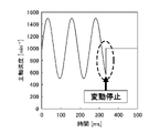
- FIG. 5 is a diagram showing time history when periodic fluctuations in the rotational speed of a spindle motor (spindle speed) are stopped in the first embodiment
- FIG. 5 is a diagram showing a time history when periodic fluctuations in the rotation speed of a conventional spindle motor (spindle speed) are stopped.
- FIG. 9 is a flow chart showing the flow of processing of the motor control device according to the second embodiment;
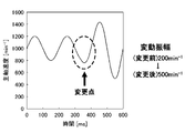
- FIG. 10 is a diagram showing a time history when the amplitude of the periodically fluctuating rotation speed (spindle speed) of the spindle motor is increased in the second embodiment;
- FIG. 10 is a diagram showing a time history when the amplitude of a periodically fluctuating rotation speed (spindle speed) in a conventional spindle motor is increased.
- FIG. 10 is a diagram showing a time history when the amplitude of the periodically fluctuating rotation speed (spindle speed) of the spindle motor is reduced in the second embodiment;
- FIG. 10 is a diagram showing a time history when the amplitude of periodically fluctuating rotation speed (spindle speed) in a conventional spindle motor is reduced;
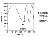
- FIG. 10 is a diagram showing a time history when the frequency of the periodically fluctuating rotation speed (spindle speed) of the spindle motor is increased in the second embodiment;
- FIG. 10 is a diagram showing a time history when the frequency of the rotational speed (spindle speed) that periodically fluctuates in a conventional spindle motor is increased.
- FIG. 10 is a diagram showing a time history when the frequency of the periodically fluctuating rotational speed (spindle speed) of the spindle motor is reduced in the second embodiment;
- FIG. 10 is a diagram showing a time history when the frequency of periodically fluctuating rotation speed (spindle speed) in a conventional spindle motor is reduced;
- FIG. 1 is a diagram showing an outline of a machine tool according to the first embodiment.
- the machine tool is a device that performs predetermined machining such as cutting by controlling the motor control device 1 and rotating the spindle motor 3 based on the speed command from the numerical control device 2 .
- This machine tool suppresses regenerative self-excited chatter vibration by periodically varying the rotation speed of the spindle motor 3, that is, by sinusoidally vibrating the rotation speed of the spindle motor 3.
- the motor control device 1 includes a fluctuation command calculation section 11 , a fluctuation stop determination section 12 , a speed control section 14 , a current control section 16 and a current detection section 17 .
- a variation command calculation unit 11 generates a variation command based on a variation condition (amplitude and/or frequency) for periodically varying a speed command of a spindle motor 3 in a machine tool and a rotation speed of the spindle motor 3, and outputs a signal output as
- the fluctuation command calculation unit 11 generates a fluctuation command for gradually changing the amplitude of the rotational speed of the spindle motor 3 that periodically fluctuates when the fluctuation condition is changed, and outputs the fluctuation command as a signal.
- the fluctuation command calculation unit 11 receives a stop command signal as a fluctuation condition from the fluctuation stop determination unit 12, the amplitude of the periodically fluctuating rotational speed of the spindle motor 3 attenuates (gradually decreases).
- the fluctuation stop determination unit 12 generates a stop command for stopping the fluctuation of the rotation speed of the spindle motor 3 based on a predetermined trigger, and outputs it as a signal.
- a signal input from outside such as the numerical controller 2, an input from a machining program, a parameter to be set, and the like are adopted as the predetermined trigger.
- Numeral 13 adds the value of the variation command output as a signal from the variation command calculator 11 to the value of the speed command output as a signal from the spindle speed command 21, and outputs the value as a signal from the speed detector 31. It means that the value obtained by subtracting the value of the actual speed feedback is input to the speed control section 14 as a signal.
- the speed control unit 14 generates a command for controlling the rotation speed of the spindle motor 3 based on the speed command and the variation command, and outputs it as a signal.
- Reference numeral 15 denotes a value obtained by subtracting the actual current feedback value output as a signal from the current detection unit 17 from the value of the command output as a signal from the speed control unit 14, which is used as a signal for current control. It means that it is input to the unit 16 .
- the current control unit 16 Based on the input signal, the current control unit 16 generates a voltage command for driving the spindle motor 3 and outputs it as a signal.
- the current detection unit 17 detects a signal that is the current value of the spindle motor 3, and outputs the detection result as an actual current feedback signal.
- the numerical controller 2 has a spindle speed command 21.
- a spindle speed command 21 generates a speed command for the spindle motor 3 and outputs it as a signal.
- the spindle motor 3 rotates under the control of the motor control device 1.
- the speed detection unit 31 detects the rotation speed of the spindle motor 3 and outputs the detection result as a signal of actual speed feedback.
- An encoder or the like is adopted for the speed detection unit 31 .
- FIG. 2 is a flowchart showing the processing flow of the motor control device 1 according to the first embodiment. The processing shown in FIG. 2 is repeatedly executed for each generation cycle (control cycle) of the variation command.
- step S11 When the fluctuation command calculation unit 11 receives a stop command signal as a fluctuation condition from the fluctuation stop determination unit 12 (YES in step S11), the process proceeds to step S12. On the other hand, if the fluctuation command calculation unit 11 has not received a stop command signal as a fluctuation condition from the fluctuation stop determination unit 12 (NO in step S11), the process proceeds to step S13.
- step S12 the value (a-ax ) as the new amplitude a, and the process proceeds to step S13.
- step S13 When the amplitude a of the rotational speed of the spindle motor 3, which periodically fluctuates, is attenuated to zero (YES in step S13), the process proceeds to step S15. On the other hand, if the amplitude a of the rotational speed of the spindle motor 3, which periodically fluctuates, is not zero (NO in step S13), the process proceeds to step S14.
- step S14 the fluctuation command calculator 11 generates a fluctuation command based on the amplitude a calculated in step S12.
- step S15 the variation command calculator 11 does not generate a variation command.
- FIG. 3 is a diagram showing the time history when periodic fluctuations in the rotational speed of the spindle motor 3 (spindle speed) are stopped in the first embodiment.
- spindle speed periodic fluctuation of the spindle speed of 1000 ⁇ 500 [min ⁇ 1 ]
- the amplitude of the spindle speed gradually attenuates to zero.
- the steepness of the speed change is moderated, the adverse effect on the quality of the machined surface is reduced.
- FIG. 4 is a diagram showing the time history when the periodic fluctuation of the rotation speed (spindle speed) of the conventional spindle motor is stopped.
- spindle speed the rotation speed of the conventional spindle motor
- the amplitude of the spindle speed suddenly becomes zero.
- mechanical shock occurs due to rapid speed change, and the excessive speed deviation deteriorates the quality of the machined surface.
- the motor control device 1 issues a variation command based on a variation condition for periodically varying the speed command of the spindle motor 3 in the machine tool and the rotation speed of the spindle motor 3. and a speed control unit 14 for controlling the rotation speed of the spindle motor 3 based on the speed command and the fluctuation command.
- a variation command is generated in which the amplitude of the rotating speed that varies gradually is changed.
- the motor control device 1 also includes a fluctuation stop determination unit 12 that generates a stop command for stopping the fluctuation of the rotation speed based on a predetermined trigger, and the fluctuation command calculation unit 11 receives the stop command as a fluctuation condition. , the amplitude of the periodically fluctuating rotational speed is attenuated to zero. As a result, especially at the time of stop, the effect of suppressing regenerative self-excited chatter vibration can be maintained, and the adverse effects of periodic fluctuations in the rotational speed of the spindle motor 3 suddenly stopped can be reduced.
- FIG. 5 is a diagram showing an outline of a machine tool according to the second embodiment.
- the same reference numerals are given to the configurations, actions, and effects that are common to those of the first embodiment, and the description thereof will be omitted as appropriate.
- the machine tool shown in FIG. 5 differs from the machine tool according to the first embodiment in that it includes a motor control device 1A instead of the motor control device 1.
- the motor control device 1A is different from the motor control device 1 in that it includes a variation condition setting section 12A instead of the variation stop determination section 12 and the like.
- the fluctuation command calculation unit 11 generates a return command that gradually changes the amplitude of the periodically fluctuating rotational speed and/or the frequency of the periodically fluctuating rotational speed when the fluctuation condition is changed. Specifically, when changing the fluctuation condition, the fluctuation command calculation unit 11 compares the values before and after the change in the amplitude of the periodically fluctuating rotational speed and/or the frequency of the periodically fluctuating rotational speed. When the value after change is larger than the value before change, a change command is generated in which the amplitude of the periodically fluctuating rotation speed and/or the frequency of the periodically fluctuating rotation speed gradually increases, and the value after change is greater than the value before change. is small, a variation command is generated that attenuates the amplitude of the periodically varying rotational speed and/or the frequency of the periodically varying rotational speed.
- the fluctuation condition setting unit 12A sets fluctuation conditions (amplitude and/or frequency) for periodically fluctuating the speed command of the spindle motor 3 and the rotation speed of the spindle motor 3 in the machine tool, and outputs them as signals. Input from the machining program, parameters to be set, and the like are adopted for setting the variable conditions.
- FIG. 6 is a flowchart showing the processing flow of the motor control device 1A according to the second embodiment. The processing shown in FIG. 6 is repeatedly executed for each generation cycle (control cycle) of the variation command.
- step S21 the fluctuation command calculation unit 11 compares the amplitude setting value a0 received as a fluctuation condition signal from the fluctuation condition setting unit 12A with the current amplitude a. If the amplitude set value a0 is greater than the current amplitude a, the process proceeds to step S22. If the amplitude set value a0 is the same as the current amplitude a, the process proceeds to step S24. If the amplitude set value a0 is smaller than the current amplitude a, the process proceeds to step S23.
- step S22 the value (a+ax) obtained by increasing the amplitude a of the periodically fluctuating rotational speed of the spindle motor 3 by a prescribed change amount ax (x: a positive value less than 1) is set as a new amplitude a. Proceed to S24.
- step S23 the value (a ⁇ ax) obtained by lowering the amplitude a of the rotational speed of the spindle motor 3, which periodically fluctuates, by a specified change amount ax (x: a positive value less than 1) is used as a new amplitude a. , the process proceeds to step S24.
- step S24 the fluctuation command calculation unit 11 compares the frequency setting value f0 received as a fluctuation condition signal from the fluctuation condition setting unit 12A with the current frequency f. If the frequency setting value f0 is greater than the current frequency f, the process proceeds to step S25. If the frequency setting value F0 is the same as the current frequency f, the process proceeds to step S27. If the frequency setting value f0 is smaller than the current amplitude f, the process proceeds to step S26.
- step S25 the value (f+fx) obtained by increasing the frequency f of the rotational speed of the spindle motor 3, which periodically fluctuates, by a specified amount of change fx (x: a positive value less than 1) is set as a new amplitude f. Proceed to S27.
- step S26 the value (f ⁇ fx) obtained by lowering the frequency f of the rotational speed of the spindle motor 3, which periodically fluctuates, by a prescribed amount of change fx (x: a positive value less than 1) is set as a new amplitude f. , the process proceeds to step S27.
- step S27 the fluctuation command calculator 11 generates a fluctuation command based on the amplitude a and the frequency f.
- FIG. 7 is a diagram showing the time history when the amplitude of the periodically fluctuating rotation speed (spindle speed) of the spindle motor 3 is increased in the second embodiment.
- spindle speed the amplitude of the periodically fluctuating rotation speed of 1000 ⁇ 200 [min ⁇ 1 ] in the spindle motor 3 is increased to 1000 ⁇ 500 [min ⁇ 1 ]
- the amplitude gradually increases. increase to That is, after changing the amplitude, the spindle speed of the spindle motor of this embodiment is smoothly changed.
- FIG. 8 is a diagram showing the time history when the amplitude of the rotational speed (spindle speed) that periodically fluctuates in a conventional spindle motor is increased. As shown in FIG. 8 , the amplitude increases sharply. That is, after changing the amplitude, the spindle speed of a conventional spindle motor changes abruptly.
- FIG. 9 is a diagram showing the time history when the amplitude of the periodically fluctuating rotation speed (spindle speed) of the spindle motor 3 is reduced in the second embodiment.
- spindle speed the amplitude of the periodically fluctuating rotation speed of 1000 ⁇ 500 [min ⁇ 1 ] in the spindle motor 3
- the spindle speed is set to 1000 ⁇ 200 [min ⁇ 1 ]
- the amplitude attenuates. (gradual decrease). That is, after changing the amplitude, the rotation speed of the spindle motor 3 of this embodiment is smoothly changed.
- FIG. 10 is a diagram showing the time history when the amplitude of the rotational speed (spindle speed) that periodically fluctuates in a conventional spindle motor is reduced.
- spindle speed the amplitude of the periodically fluctuating spindle speed of 1000 ⁇ 500 [min ⁇ 1 ] in the conventional spindle motor is reduced and the spindle speed is set to 1000 ⁇ 200 [min ⁇ 1 ]
- the amplitude is Decrease abruptly. That is, after changing the amplitude, the spindle speed of a conventional spindle motor changes abruptly.
- FIG. 11 is a diagram showing the time history when the frequency of the periodically fluctuating rotation speed (spindle speed) of the spindle motor 3 is increased in the second embodiment.
- spindle speed the frequency gradually increases. That is, after changing the frequency, the spindle speed of the spindle motor 3 of this embodiment is smoothly changed.
- FIG. 12 is a diagram showing the time history when the periodically fluctuating rotational speed (spindle speed) of a conventional spindle motor is increased.
- spindle speed the periodically fluctuating rotational speed
- FIG. 12 when the period 2 [Hz] of the periodically fluctuating spindle speed 1000 ⁇ 500 [min ⁇ 1 ] in the conventional spindle motor is increased to 8 [Hz], the frequency increases sharply. . That is, after changing the frequency, the spindle speed of the conventional spindle motor changes abruptly.
- FIG. 13 is a diagram showing the time history when the frequency of the periodically fluctuating rotation speed (spindle speed) of the spindle motor 3 is reduced in the second embodiment.
- spindle speed the frequency attenuates (gradually decreases )do. That is, after changing the frequency, the spindle speed of the spindle motor 3 of this embodiment is smoothly changed.
- FIG. 14 shows the time history when the frequency of the periodically fluctuating rotation speed (spindle speed) in a conventional spindle motor is reduced.
- spindle speed the frequency of the periodically fluctuating rotation speed (spindle speed) in a conventional spindle motor is reduced.
- the frequency sharply decreases. . That is, after changing the frequency, the spindle speed of the conventional spindle motor changes abruptly.
- the motor control device 1A issues a variation command based on the variation condition for periodically varying the speed command of the spindle motor 3 in the machine tool and the rotational speed of the spindle motor 3. and a speed control unit 14 for controlling the rotation speed of the spindle motor 3 based on the speed command and the fluctuation command.
- a variation command is generated in which the amplitude of the rotational speed that fluctuates and/or the frequency of the rotational speed that periodically fluctuates is gradually changed.
- the fluctuation command calculation unit 11 compares the values before and after the change in the amplitude of the periodically fluctuating rotational speed and/or the frequency of the periodically fluctuating rotational speed, and compares the values before the change.
- the value after change is large, the amplitude of the periodically fluctuating rotation speed and/or the frequency of the periodically fluctuating rotation speed gradually increases to generate a fluctuation command, and the value after the change is smaller than the value before the change.
- a variation command is generated in which the amplitude of the periodically varying rotational speed and/or the frequency of the periodically varying rotational speed are attenuated.
- the motor control device 1A it is possible to more reliably reduce the adverse effects caused by sudden changes in periodic fluctuations in the rotation speed of the spindle motor 3 while maintaining the effect of suppressing regenerative self-excited chatter vibration. .
- the motor control devices 1 and 1A can be realized by hardware, software, or a combination thereof. Also, the control method performed by the motor control devices 1 and 1A can be realized by hardware, software, or a combination thereof. Note that "implemented by software” means implemented by a computer reading and executing a program.
Landscapes
- Engineering & Computer Science (AREA)
- Human Computer Interaction (AREA)
- Manufacturing & Machinery (AREA)
- Physics & Mathematics (AREA)
- General Physics & Mathematics (AREA)
- Automation & Control Theory (AREA)
- Mechanical Engineering (AREA)
- Automatic Control Of Machine Tools (AREA)
- Numerical Control (AREA)
- Control Of Electric Motors In General (AREA)
Abstract
Description
これにより、速度変化の急峻を緩やかにするため、再生型の自励びびり振動の抑制効果を維持しつつ、主軸モータ3の回転速度の周期的な変動の急な変更による悪影響を低減できる。
これにより、特に停止時において、再生型の自励びびり振動の抑制効果を維持しつつ、主軸モータ3の回転速度の周期的な変動の急な停止による悪影響を低減できる。
これにより、モータ制御装置1Aによれば、速度変化の急峻を緩やかにするため、再生型の自励びびり振動の抑制効果を維持しつつ、主軸モータ3の回転速度の周期的な変動の急な変更による悪影響を低減できる。
これにより、モータ制御装置1Aによれば、より確実に、再生型の自励びびり振動の抑制効果を維持しつつ、主軸モータ3の回転速度の周期的な変動の急な変更による悪影響を低減できる。
11 変動指令計算部
12 変動停止判定部
12A 変動条件設定部
14 速度制御部
16 電流制御部
17 電流検出部
2 数値制御装置
21 主軸速度指令
3 主軸モータ
31 速度検出部
Claims (3)
- 工作機械における主軸モータの速度指令及び前記主軸モータの回転速度を周期的に変動させるための変動条件に基づいて変動指令を生成する変動指令計算部と、
前記速度指令及び前記変動指令に基づいて前記主軸モータの回転速度を制御する速度制御部と、を備え、
前記変動指令計算部は、前記変動条件の変更時に、周期的に変動する前記回転速度の振幅及び/又は周期的に変動する前記回転速度の周波数が徐々に変更される前記変動指令を生成する、工作機械の制御装置。 - 所定のトリガに基づいて、前記回転速度の変動を停止させる停止指令を生成する変動停止判定部を備え、
前記変動指令計算部は、前記変動条件として前記停止指令を受け取った場合に、周期的に変動する前記回転速度の振幅が減衰してゼロになる前記変動指令を生成する、請求項1に記載の工作機械の制御装置。 - 前記変動指令計算部は、前記変動条件の変更時に、周期的に変動する前記回転速度の振幅及び/又は周期的に変動する前記回転速度の周波数の変更前後の値を比較し、変更前の値より変更後の値が大きいときには周期的に変動する前記回転速度の振幅及び/又は周期的に変動する前記回転速度の周波数が徐々に増大する前記変動指令を生成し、変更前の値より変更後の値が小さいときには周期的に変動する前記回転速度の振幅及び/又は周期的に変動する前記回転速度の周波数が減衰する前記変動指令を生成する、請求項1に記載の工作機械の制御装置。
Priority Applications (4)
| Application Number | Priority Date | Filing Date | Title |
|---|---|---|---|
| JP2023507110A JP7575569B2 (ja) | 2021-03-18 | 2022-03-14 | 工作機械の制御装置 |
| CN202280013761.3A CN116847946B (zh) | 2021-03-18 | 2022-03-14 | 机床的控制装置 |
| DE112022000593.9T DE112022000593T5 (de) | 2021-03-18 | 2022-03-14 | Steuerungsvorrichtung für eine Werkzeugmaschine |
| US18/549,545 US12436523B2 (en) | 2021-03-18 | 2022-03-14 | Control device for machine tool |
Applications Claiming Priority (2)
| Application Number | Priority Date | Filing Date | Title |
|---|---|---|---|
| JP2021-044443 | 2021-03-18 | ||
| JP2021044443 | 2021-03-18 |
Publications (1)
| Publication Number | Publication Date |
|---|---|
| WO2022196646A1 true WO2022196646A1 (ja) | 2022-09-22 |
Family
ID=83320386
Family Applications (1)
| Application Number | Title | Priority Date | Filing Date |
|---|---|---|---|
| PCT/JP2022/011373 Ceased WO2022196646A1 (ja) | 2021-03-18 | 2022-03-14 | 工作機械の制御装置 |
Country Status (5)
| Country | Link |
|---|---|
| US (1) | US12436523B2 (ja) |
| JP (1) | JP7575569B2 (ja) |
| CN (1) | CN116847946B (ja) |
| DE (1) | DE112022000593T5 (ja) |
| WO (1) | WO2022196646A1 (ja) |
Families Citing this family (1)
| Publication number | Priority date | Publication date | Assignee | Title |
|---|---|---|---|---|
| CN116209532B (zh) * | 2020-07-29 | 2025-07-11 | 发那科株式会社 | 机床的控制装置 |
Citations (2)
| Publication number | Priority date | Publication date | Assignee | Title |
|---|---|---|---|---|
| JP2018180990A (ja) * | 2017-04-14 | 2018-11-15 | ファナック株式会社 | 揺動切削を行う工作機械の制御装置 |
| JP2020196057A (ja) * | 2019-05-31 | 2020-12-10 | 株式会社ジェイテクト | 歯車加工装置及び歯車加工方法 |
Family Cites Families (12)
| Publication number | Priority date | Publication date | Assignee | Title |
|---|---|---|---|---|
| JP2002283186A (ja) * | 2001-03-27 | 2002-10-03 | Toshiba Mach Co Ltd | 工作機械、工作機械の数値制御装置および振動防止方法 |
| US6936990B2 (en) * | 2002-03-29 | 2005-08-30 | Matsushita Electric Industrial Co., Ltd. | Method for controlling electric motor and apparatus for controlling the same |
| KR100497660B1 (ko) * | 2004-06-07 | 2005-07-01 | 인하대학교 산학협력단 | Nc선반에서 발생하는 채터진동 감지장치 및 방법 |
| JP5215064B2 (ja) * | 2008-07-17 | 2013-06-19 | オークマ株式会社 | 工作機械のびびり振動抑制方法及びその装置 |
| CN104773069A (zh) * | 2010-07-30 | 2015-07-15 | 株式会社日本自动车部品综合研究所 | 车辆动力传动装置 |
| JP5525411B2 (ja) * | 2010-10-25 | 2014-06-18 | オークマ株式会社 | 振動抑制方法及び振動抑制装置 |
| JP5665047B2 (ja) | 2010-10-27 | 2015-02-04 | オークマ株式会社 | 工作機械 |
| JP5852467B2 (ja) * | 2012-02-23 | 2016-02-03 | オークマ株式会社 | 数値制御装置 |
| JP5908342B2 (ja) * | 2012-05-17 | 2016-04-26 | オークマ株式会社 | 工作機械の加工振動抑制方法及び加工振動抑制装置 |
| JP5860072B2 (ja) * | 2014-02-12 | 2016-02-16 | ファナック株式会社 | ねじ切り中のびびりの発生を抑制する機能を備えた数値制御装置 |
| JP6625794B2 (ja) * | 2014-05-21 | 2019-12-25 | Dmg森精機株式会社 | びびり振動を抑制可能な主軸安定回転数の算出方法、その報知方法、主軸回転数制御方法及びncプログラム編集方法、並びにその装置。 |
| JP7134035B2 (ja) * | 2018-09-07 | 2022-09-09 | オークマ株式会社 | 工作機械の振動抑制装置及び振動抑制方法 |
-
2022
- 2022-03-14 WO PCT/JP2022/011373 patent/WO2022196646A1/ja not_active Ceased
- 2022-03-14 CN CN202280013761.3A patent/CN116847946B/zh active Active
- 2022-03-14 DE DE112022000593.9T patent/DE112022000593T5/de active Pending
- 2022-03-14 JP JP2023507110A patent/JP7575569B2/ja active Active
- 2022-03-14 US US18/549,545 patent/US12436523B2/en active Active
Patent Citations (2)
| Publication number | Priority date | Publication date | Assignee | Title |
|---|---|---|---|---|
| JP2018180990A (ja) * | 2017-04-14 | 2018-11-15 | ファナック株式会社 | 揺動切削を行う工作機械の制御装置 |
| JP2020196057A (ja) * | 2019-05-31 | 2020-12-10 | 株式会社ジェイテクト | 歯車加工装置及び歯車加工方法 |
Also Published As
| Publication number | Publication date |
|---|---|
| US20240152116A1 (en) | 2024-05-09 |
| CN116847946A (zh) | 2023-10-03 |
| JP7575569B2 (ja) | 2024-10-29 |
| US12436523B2 (en) | 2025-10-07 |
| DE112022000593T5 (de) | 2023-10-26 |
| JPWO2022196646A1 (ja) | 2022-09-22 |
| CN116847946B (zh) | 2025-11-14 |
Similar Documents
| Publication | Publication Date | Title |
|---|---|---|
| JP5908342B2 (ja) | 工作機械の加工振動抑制方法及び加工振動抑制装置 | |
| JP4174543B2 (ja) | サーボモータの制御装置 | |
| JP5258921B2 (ja) | 工作機械及びその加工制御装置 | |
| US8135491B2 (en) | Method, system and apparatus for on-demand integrated adaptive control of machining operations | |
| JP7444697B2 (ja) | 数値制御装置、制御プログラム及び制御方法 | |
| JP2012213830A5 (ja) | ||
| JP7453330B2 (ja) | 工作機械の制御装置 | |
| JP2020163487A (ja) | サーボ制御装置 | |
| JP7575569B2 (ja) | 工作機械の制御装置 | |
| JP7036786B2 (ja) | 数値制御装置、プログラム及び制御方法 | |
| WO2011058645A1 (ja) | 工作機械の制御方法および制御装置 | |
| JP7464721B2 (ja) | 工作機械の制御装置 | |
| JP4848393B2 (ja) | 工作機械の制御方法および制御装置 | |
| JP5499865B2 (ja) | 多関節型ロボットの速度指令プロファイルの生成方法 | |
| US20240227106A9 (en) | Machine tool controller | |
| JP5947113B2 (ja) | 工作機械を用いた被加工物の加工方法 | |
| JP5767931B2 (ja) | 工作機械の振動抑制方法および振動抑制装置 | |
| JP5301946B2 (ja) | 振動抑制方法及び装置 | |
| WO2024053027A1 (ja) | 工作機械制御装置および工作機械制御プログラム | |
| JP7544840B2 (ja) | 工作機械の制御装置 | |
| CN121669980A (zh) | 控制装置以及计算装置 | |
| WO2023067683A1 (ja) | 工作機械の制御装置 | |
| JP2024115672A (ja) | 工作機械及び工作機械の加工条件決定方法 | |
| WO2022249317A1 (ja) | 工作機械の制御装置 | |
| WO2025134234A1 (ja) | 工作機械の制御装置 |
Legal Events
| Date | Code | Title | Description |
|---|---|---|---|
| 121 | Ep: the epo has been informed by wipo that ep was designated in this application |
Ref document number: 22771392 Country of ref document: EP Kind code of ref document: A1 |
|
| WWE | Wipo information: entry into national phase |
Ref document number: 2023507110 Country of ref document: JP |
|
| WWE | Wipo information: entry into national phase |
Ref document number: 202280013761.3 Country of ref document: CN |
|
| WWE | Wipo information: entry into national phase |
Ref document number: 18549545 Country of ref document: US |
|
| WWE | Wipo information: entry into national phase |
Ref document number: 112022000593 Country of ref document: DE |
|
| 122 | Ep: pct application non-entry in european phase |
Ref document number: 22771392 Country of ref document: EP Kind code of ref document: A1 |
|
| WWG | Wipo information: grant in national office |
Ref document number: 18549545 Country of ref document: US |