WO2022196558A1 - 真空ポンプ、真空ポンプの制御装置及びリモート制御装置 - Google Patents
真空ポンプ、真空ポンプの制御装置及びリモート制御装置 Download PDFInfo
- Publication number
- WO2022196558A1 WO2022196558A1 PCT/JP2022/010896 JP2022010896W WO2022196558A1 WO 2022196558 A1 WO2022196558 A1 WO 2022196558A1 JP 2022010896 W JP2022010896 W JP 2022010896W WO 2022196558 A1 WO2022196558 A1 WO 2022196558A1
- Authority
- WO
- WIPO (PCT)
- Prior art keywords
- control device
- pump
- turbo
- command signal
- remote
- Prior art date
Links
- 230000008859 change Effects 0.000 claims description 74
- 238000001816 cooling Methods 0.000 claims description 29
- 238000010438 heat treatment Methods 0.000 claims description 13
- 230000008054 signal transmission Effects 0.000 claims description 8
- 239000004065 semiconductor Substances 0.000 abstract description 43
- 238000004519 manufacturing process Methods 0.000 abstract description 35
- 238000004891 communication Methods 0.000 description 84
- 239000007789 gas Substances 0.000 description 63
- 238000000034 method Methods 0.000 description 52
- 230000008569 process Effects 0.000 description 49
- 238000001514 detection method Methods 0.000 description 18
- XEEYBQQBJWHFJM-UHFFFAOYSA-N Iron Chemical compound [Fe] XEEYBQQBJWHFJM-UHFFFAOYSA-N 0.000 description 14
- 230000006870 function Effects 0.000 description 14
- 229910052751 metal Inorganic materials 0.000 description 14
- 239000002184 metal Substances 0.000 description 14
- XLYOFNOQVPJJNP-UHFFFAOYSA-N water Substances O XLYOFNOQVPJJNP-UHFFFAOYSA-N 0.000 description 14
- 125000006850 spacer group Chemical group 0.000 description 13
- 238000003860 storage Methods 0.000 description 12
- 230000002093 peripheral effect Effects 0.000 description 10
- 238000004804 winding Methods 0.000 description 9
- FFBHFFJDDLITSX-UHFFFAOYSA-N benzyl N-[2-hydroxy-4-(3-oxomorpholin-4-yl)phenyl]carbamate Chemical compound OC1=C(NC(=O)OCC2=CC=CC=C2)C=CC(=C1)N1CCOCC1=O FFBHFFJDDLITSX-UHFFFAOYSA-N 0.000 description 8
- 239000000498 cooling water Substances 0.000 description 8
- 230000005284 excitation Effects 0.000 description 8
- 229910052742 iron Inorganic materials 0.000 description 7
- 229910052782 aluminium Inorganic materials 0.000 description 6
- XAGFODPZIPBFFR-UHFFFAOYSA-N aluminium Chemical compound [Al] XAGFODPZIPBFFR-UHFFFAOYSA-N 0.000 description 6
- 239000010935 stainless steel Substances 0.000 description 5
- 229910001220 stainless steel Inorganic materials 0.000 description 5
- 239000000758 substrate Substances 0.000 description 5
- RYGMFSIKBFXOCR-UHFFFAOYSA-N Copper Chemical compound [Cu] RYGMFSIKBFXOCR-UHFFFAOYSA-N 0.000 description 4
- 229910052802 copper Inorganic materials 0.000 description 4
- 239000010949 copper Substances 0.000 description 4
- 230000004048 modification Effects 0.000 description 4
- 238000012986 modification Methods 0.000 description 4
- 229910045601 alloy Inorganic materials 0.000 description 3
- 239000000956 alloy Substances 0.000 description 3
- 230000008901 benefit Effects 0.000 description 3
- 238000012790 confirmation Methods 0.000 description 3
- 238000005530 etching Methods 0.000 description 3
- 150000002739 metals Chemical class 0.000 description 3
- 238000010926 purge Methods 0.000 description 3
- 230000005856 abnormality Effects 0.000 description 2
- VSCWAEJMTAWNJL-UHFFFAOYSA-K aluminium trichloride Chemical compound Cl[Al](Cl)Cl VSCWAEJMTAWNJL-UHFFFAOYSA-K 0.000 description 2
- 230000005540 biological transmission Effects 0.000 description 2
- 230000006835 compression Effects 0.000 description 2
- 238000007906 compression Methods 0.000 description 2
- 230000007423 decrease Effects 0.000 description 2
- 238000010586 diagram Methods 0.000 description 2
- 238000006073 displacement reaction Methods 0.000 description 2
- 238000012423 maintenance Methods 0.000 description 2
- 239000000463 material Substances 0.000 description 2
- 239000000203 mixture Substances 0.000 description 2
- 230000035699 permeability Effects 0.000 description 2
- 238000012545 processing Methods 0.000 description 2
- 238000005086 pumping Methods 0.000 description 2
- 230000008929 regeneration Effects 0.000 description 2
- 238000011069 regeneration method Methods 0.000 description 2
- 230000004044 response Effects 0.000 description 2
- 239000007787 solid Substances 0.000 description 2
- 229910000838 Al alloy Inorganic materials 0.000 description 1
- 229910003910 SiCl4 Inorganic materials 0.000 description 1
- 230000001133 acceleration Effects 0.000 description 1
- 230000009471 action Effects 0.000 description 1
- 230000004913 activation Effects 0.000 description 1
- 230000015572 biosynthetic process Effects 0.000 description 1
- 238000007664 blowing Methods 0.000 description 1
- 239000003990 capacitor Substances 0.000 description 1
- 230000003247 decreasing effect Effects 0.000 description 1
- 230000006866 deterioration Effects 0.000 description 1
- 239000004973 liquid crystal related substance Substances 0.000 description 1
- 230000007257 malfunction Effects 0.000 description 1
- 238000012544 monitoring process Methods 0.000 description 1
- 238000002360 preparation method Methods 0.000 description 1
- 239000000047 product Substances 0.000 description 1
- 230000001681 protective effect Effects 0.000 description 1
- FDNAPBUWERUEDA-UHFFFAOYSA-N silicon tetrachloride Chemical compound Cl[Si](Cl)(Cl)Cl FDNAPBUWERUEDA-UHFFFAOYSA-N 0.000 description 1
- 239000012265 solid product Substances 0.000 description 1
- 230000000087 stabilizing effect Effects 0.000 description 1
Images


Classifications
-
- F—MECHANICAL ENGINEERING; LIGHTING; HEATING; WEAPONS; BLASTING
- F04—POSITIVE - DISPLACEMENT MACHINES FOR LIQUIDS; PUMPS FOR LIQUIDS OR ELASTIC FLUIDS
- F04D—NON-POSITIVE-DISPLACEMENT PUMPS
- F04D19/00—Axial-flow pumps
- F04D19/02—Multi-stage pumps
- F04D19/04—Multi-stage pumps specially adapted to the production of a high vacuum, e.g. molecular pumps
-
- G—PHYSICS
- G05—CONTROLLING; REGULATING
- G05B—CONTROL OR REGULATING SYSTEMS IN GENERAL; FUNCTIONAL ELEMENTS OF SUCH SYSTEMS; MONITORING OR TESTING ARRANGEMENTS FOR SUCH SYSTEMS OR ELEMENTS
- G05B19/00—Programme-control systems
- G05B19/02—Programme-control systems electric
- G05B19/04—Programme control other than numerical control, i.e. in sequence controllers or logic controllers
- G05B19/042—Programme control other than numerical control, i.e. in sequence controllers or logic controllers using digital processors
-
- F—MECHANICAL ENGINEERING; LIGHTING; HEATING; WEAPONS; BLASTING
- F04—POSITIVE - DISPLACEMENT MACHINES FOR LIQUIDS; PUMPS FOR LIQUIDS OR ELASTIC FLUIDS
- F04D—NON-POSITIVE-DISPLACEMENT PUMPS
- F04D19/00—Axial-flow pumps
- F04D19/02—Multi-stage pumps
- F04D19/04—Multi-stage pumps specially adapted to the production of a high vacuum, e.g. molecular pumps
- F04D19/042—Turbomolecular vacuum pumps
-
- F—MECHANICAL ENGINEERING; LIGHTING; HEATING; WEAPONS; BLASTING
- F04—POSITIVE - DISPLACEMENT MACHINES FOR LIQUIDS; PUMPS FOR LIQUIDS OR ELASTIC FLUIDS
- F04D—NON-POSITIVE-DISPLACEMENT PUMPS
- F04D27/00—Control, e.g. regulation, of pumps, pumping installations or pumping systems specially adapted for elastic fluids
- F04D27/02—Surge control
- F04D27/0261—Surge control by varying driving speed
-
- F—MECHANICAL ENGINEERING; LIGHTING; HEATING; WEAPONS; BLASTING
- F04—POSITIVE - DISPLACEMENT MACHINES FOR LIQUIDS; PUMPS FOR LIQUIDS OR ELASTIC FLUIDS
- F04D—NON-POSITIVE-DISPLACEMENT PUMPS
- F04D27/00—Control, e.g. regulation, of pumps, pumping installations or pumping systems specially adapted for elastic fluids
- F04D27/02—Surge control
- F04D27/0276—Surge control by influencing fluid temperature
-
- F—MECHANICAL ENGINEERING; LIGHTING; HEATING; WEAPONS; BLASTING
- F04—POSITIVE - DISPLACEMENT MACHINES FOR LIQUIDS; PUMPS FOR LIQUIDS OR ELASTIC FLUIDS
- F04D—NON-POSITIVE-DISPLACEMENT PUMPS
- F04D29/00—Details, component parts, or accessories
- F04D29/58—Cooling; Heating; Diminishing heat transfer
- F04D29/582—Cooling; Heating; Diminishing heat transfer specially adapted for elastic fluid pumps
- F04D29/584—Cooling; Heating; Diminishing heat transfer specially adapted for elastic fluid pumps cooling or heating the machine
-
- G—PHYSICS
- G05—CONTROLLING; REGULATING
- G05B—CONTROL OR REGULATING SYSTEMS IN GENERAL; FUNCTIONAL ELEMENTS OF SUCH SYSTEMS; MONITORING OR TESTING ARRANGEMENTS FOR SUCH SYSTEMS OR ELEMENTS
- G05B23/00—Testing or monitoring of control systems or parts thereof
- G05B23/02—Electric testing or monitoring
-
- G—PHYSICS
- G08—SIGNALLING
- G08C—TRANSMISSION SYSTEMS FOR MEASURED VALUES, CONTROL OR SIMILAR SIGNALS
- G08C17/00—Arrangements for transmitting signals characterised by the use of a wireless electrical link
-
- F—MECHANICAL ENGINEERING; LIGHTING; HEATING; WEAPONS; BLASTING
- F05—INDEXING SCHEMES RELATING TO ENGINES OR PUMPS IN VARIOUS SUBCLASSES OF CLASSES F01-F04
- F05D—INDEXING SCHEME FOR ASPECTS RELATING TO NON-POSITIVE-DISPLACEMENT MACHINES OR ENGINES, GAS-TURBINES OR JET-PROPULSION PLANTS
- F05D2270/00—Control
- F05D2270/30—Control parameters, e.g. input parameters
- F05D2270/301—Pressure
- F05D2270/3015—Pressure differential pressure
-
- F—MECHANICAL ENGINEERING; LIGHTING; HEATING; WEAPONS; BLASTING
- F05—INDEXING SCHEMES RELATING TO ENGINES OR PUMPS IN VARIOUS SUBCLASSES OF CLASSES F01-F04
- F05D—INDEXING SCHEME FOR ASPECTS RELATING TO NON-POSITIVE-DISPLACEMENT MACHINES OR ENGINES, GAS-TURBINES OR JET-PROPULSION PLANTS
- F05D2270/00—Control
- F05D2270/30—Control parameters, e.g. input parameters
- F05D2270/303—Temperature
-
- F—MECHANICAL ENGINEERING; LIGHTING; HEATING; WEAPONS; BLASTING
- F05—INDEXING SCHEMES RELATING TO ENGINES OR PUMPS IN VARIOUS SUBCLASSES OF CLASSES F01-F04
- F05D—INDEXING SCHEME FOR ASPECTS RELATING TO NON-POSITIVE-DISPLACEMENT MACHINES OR ENGINES, GAS-TURBINES OR JET-PROPULSION PLANTS
- F05D2270/00—Control
- F05D2270/30—Control parameters, e.g. input parameters
- F05D2270/306—Mass flow
- F05D2270/3061—Mass flow of the working fluid
-
- G—PHYSICS
- G05—CONTROLLING; REGULATING
- G05B—CONTROL OR REGULATING SYSTEMS IN GENERAL; FUNCTIONAL ELEMENTS OF SUCH SYSTEMS; MONITORING OR TESTING ARRANGEMENTS FOR SUCH SYSTEMS OR ELEMENTS
- G05B2219/00—Program-control systems
- G05B2219/20—Pc systems
- G05B2219/23—Pc programming
- G05B2219/23051—Remote control, enter program remote, detachable programmer
Definitions
- the present invention relates to a vacuum pump, a vacuum pump control device, and a remote control device.
- Patent Literature 1 discloses a turbo-molecular pump that evacuates the chamber of a semiconductor manufacturing apparatus and exhausts process gas used for manufacturing semiconductors from the chamber.
- a base portion is provided at the bottom of the outer cylinder of the turbomolecular pump described in Patent Document 1, and a heater for heating the base portion and a water cooling pipe for cooling the base portion are provided on the outer circumference of the base portion. are placed.
- the turbomolecular pump described in Patent Document 1 includes a sensor that measures the temperature of a motor that rotates a rotor blade, a sensor that measures the internal temperature of a base, and a sensor that measures the temperature of the outside of the base. , sends the detection signals of these sensors to the controller.
- This control device can send an on/off control command signal to the heater provided in the turbo-molecular pump, and send an on-off control command to a solenoid valve that controls the flow of cooling water to the cooling water pipe provided in the turbo-molecular pump. is configured to When the controller sends an ON command signal to the solenoid valve, the solenoid valve opens and cooling water flows through the water-cooled pipe, and when an OFF command signal is sent, the solenoid valve closes and the cooling water stops flowing through the water-cooled pipe.
- the optimum pump is usually selected according to the predetermined process. It was necessary to prepare a pump with the specifications of
- the user may wish to change the operation specifications of the turbomolecular pump.
- the user or field service engineer goes to the place where the turbo-molecular pump and the control device are installed, and attaches or detaches the specification-changing device that changes the operation specifications of the turbo-molecular pump, and after detaching the device, the control device manual operation of the turbomolecular pump requires inputting instructions to change settings related to the operation specifications of the turbomolecular pump, which poses a problem of a heavy workload on the user and the field service engineer.
- the vacuum pump of the present invention is a pump body for exhausting the gas inside the exhaust target device; a control device for controlling the pump body; A vacuum pump comprising
- the control device is Remote signal receiving means for receiving a command signal from a remote control device for remotely controlling the pump body, It is characterized in that, based on the command signal received by the remote signal receiving means, settings related to the operation specifications of the pump main body are changed.
- the control device When the remote signal receiving means receives the command signal from the remote control device while the pump body is operating, the control device responds to the command signal without stopping the operation of the pump body.
- the setting may be changed based on the above.
- control device may change settings related to the operation of the specification changing device based on the command signal received by the remote signal receiving means.
- the specification changing device may be heating means for heating the pump body or cooling means for cooling the pump body.
- another vacuum pump of the present invention includes: A vacuum pump having a pump body for evacuating gas inside a device to be evacuated, a controlled device capable of changing operation specifications of the pump main body; and a specification setting device that changes settings related to the operation specification of the pump body by changing the operation specification of the device to be controlled.
- the vacuum pump control device of the present invention includes: a control means for controlling a pump body that exhausts the gas inside the exhaust target device; remote signal receiving means for receiving a command signal from a remote control device for remotely controlling the pump main body; A control device for a vacuum pump comprising The control means is characterized in that, based on the command signal received by the remote signal receiving means, the setting related to the operating specifications of the pump main body is changed.
- the remote control device of the present invention includes: Remote signal transmission means for transmitting a command signal to a control device that controls a pump body that exhausts gas inside the exhaust target device; remote control means for remotely controlling the pump body by causing the remote signal transmission means to transmit the command signal to the control device;
- a remote control device comprising The remote control means causes the remote signal transmission means to transmit the command signal to the control device, thereby causing the control device to change settings related to operation specifications of the pump body based on the received command signal. It is characterized by
- a vacuum pump a control device for the vacuum pump, and a remote control device that can reduce the workload of users and field service engineers.
- FIG. 1 is a longitudinal sectional view of a turbomolecular pump according to an embodiment of the invention
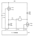
- FIG. 1 is a circuit diagram of an amplifier circuit according to an embodiment of the present invention
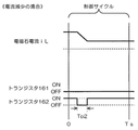
- FIG. 4 is a time chart showing control when a current command value is greater than a detected value according to the embodiment of the present invention
- 4 is a time chart showing control when a current command value is smaller than a detected value according to the embodiment of the present invention
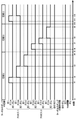
- 4 is a timing chart for explaining changes in specifications of the turbo-molecular pump according to the embodiment of the present invention;
- the vacuum pump system 1 shown in FIG. 1 exhausts gases such as air and process gas inside the semiconductor manufacturing apparatus X.
- the semiconductor manufacturing apparatus X includes a chamber XR, and manufactures semiconductors by executing various processes for manufacturing semiconductors inside the chamber XR. Specific examples of processes executed by the semiconductor manufacturing apparatus X inside the chamber XR include a process of forming a circuit on a semiconductor substrate by etching or film formation, a process of introducing a process gas into the chamber XR, and applying the process gas to the semiconductor substrate. and the like.
- the semiconductor manufacturing apparatus X is an example of an exhaust target apparatus. In the present embodiment, the semiconductor manufacturing apparatus X is described as the target device for evacuation, but this is only an example, and the target device for evacuation may be any device.
- the vacuum pump system 1 includes a vacuum pump 10 and a remote control device 300, as shown in FIG.
- the vacuum pump 10 is attached to the chamber XR of the semiconductor manufacturing apparatus X, and includes a turbo-molecular pump 100 that exhausts the gas inside the chamber XR, and a control device 200 that controls the turbo-molecular pump 100 and monitors the operating state.
- Turbomolecular pump 100 is an example of a pump body. In the present embodiment, the explanation is given assuming that the pump main body is the turbo-molecular pump 100, but this is only an example. It may be a vacuum pump.
- the control device 200 is connected to the turbomolecular pump 100 by a connection cable 11 that is a signal transmission path, and transmits and receives signals by wire communication with the turbomolecular pump 100 via the connection cable 11 .
- the control device 200 controls the operation of the turbomolecular pump 100 by sending command signals to the turbomolecular pump 100 via the connection cable 11 .
- the control device 200 monitors the operating state of the turbo-molecular pump 100 by receiving detection signals output from various sensors included in the turbo-molecular pump 100 via the connection cable 11 .
- the turbo-molecular pump 100 and the control device 200 are provided independently of each other, and are connected to each other via the connection cable 11. However, this is only an example, and the turbo-molecular pump 100 and control device 200 may be integrated into a single device.
- the control device 200 transmits and receives signals by performing remote communication with the remote control device 300 .
- the control device 200 may transmit and receive signals by performing remote communication with the remote control device 300 via a communication cable, or may transmit and receive signals by performing wireless communication with the remote control device 300 . may be sent and received.
- the control device 200 receives a command signal from the remote control device 300 by remote communication, and controls the turbomolecular pump 100 according to the received command signal.
- the remote control device 300 remotely controls the turbomolecular pump 100 according to instructions from a user (for example, a worker at the factory where the semiconductor manufacturing apparatus X is installed).
- FIG. 2 A longitudinal sectional view of this turbo-molecular pump 100 is shown in FIG.
- the turbo-molecular pump 100 has an intake port 101 formed at the upper end of a cylindrical outer cylinder 127 .
- a rotating body 103 having a plurality of rotating blades 102 (102a, 102b, 102c, . is provided inside the outer cylinder 127.
- a rotor shaft 113 is attached to the center of the rotor 103, and the rotor shaft 113 is levitated in the air and position-controlled by, for example, a 5-axis control magnetic bearing.
- the rotor 103 is generally made of metal such as aluminum or aluminum alloy.
- the upper radial electromagnet 104 has four electromagnets arranged in pairs on the X-axis and the Y-axis.
- Four upper radial sensors 107 are provided adjacent to the upper radial electromagnets 104 and corresponding to the upper radial electromagnets 104, respectively.
- the upper radial sensor 107 is, for example, an inductance sensor or an eddy current sensor having a conductive winding, and detects the position of the rotor shaft 113 based on the change in the inductance of this conductive winding, which changes according to the position of the rotor shaft 113 .
- This upper radial sensor 107 is configured to detect the radial displacement of the rotor shaft 113 , ie the rotor 103 fixed thereto, and send it to the controller 200 .
- a compensation circuit having a PID adjustment function generates an excitation control command signal for the upper radial electromagnet 104 based on the position signal detected by the upper radial sensor 107, as shown in FIG.
- An amplifier circuit 150 controls the excitation of the upper radial electromagnet 104 based on the excitation control command signal, thereby adjusting the upper radial position of the rotor shaft 113 .
- the rotor shaft 113 is made of a high magnetic permeability material (iron, stainless steel, etc.) or the like, and is attracted by the magnetic force of the upper radial electromagnet 104 . Such adjustments are made independently in the X-axis direction and the Y-axis direction.
- the lower radial electromagnet 105 and the lower radial sensor 108 are arranged in the same manner as the upper radial electromagnet 104 and the upper radial sensor 107 so that the lower radial position of the rotor shaft 113 is set to the upper radial position. adjusted in the same way.
- a compensation circuit having, for example, a PID adjustment function generates an excitation control command signal for each of the axial electromagnets 106A and 106B based on the axial position signal detected by the axial sensor 109.
- the amplifier circuit 150 controls the excitation of the axial electromagnets 106A and 106B, respectively.
- the axial electromagnet 106B attracts the metal disk 111 downward, and the axial position of the rotor shaft 113 is adjusted.
- control device 200 appropriately adjusts the magnetic force exerted on the metal disk 111 by the axial electromagnets 106A and 106B, magnetically levitates the rotor shaft 113 in the axial direction, and holds the rotor shaft 113 in the space without contact. ing.
- the amplifier circuit 150 that controls the excitation of the upper radial electromagnet 104, the lower radial electromagnet 105, and the axial electromagnets 106A and 106B will be described later.
- the motor 121 has a plurality of magnetic poles circumferentially arranged to surround the rotor shaft 113 .
- Each magnetic pole is controlled by the control device 200 so as to rotationally drive the rotor shaft 113 via an electromagnetic force acting between the magnetic poles and the rotor shaft 113 .
- the motor 121 incorporates a rotation speed sensor (not shown) such as a Hall element, resolver, encoder, etc., and the rotation speed of the rotor shaft 113 is detected by the detection signal of this rotation speed sensor.
- phase sensor (not shown) is attached, for example, near the lower radial direction sensor 108 to detect the phase of rotation of the rotor shaft 113 .
- the control device 200 detects the position of the magnetic pole using both the detection signals from the phase sensor and the rotational speed sensor.
- a plurality of fixed wings 123 (123a, 123b, 123c%) are arranged with a slight gap from the rotary wings 102 (102a, 102b, 102c).
- the rotor blades 102 (102a, 102b, 102c, . . . ) are inclined at a predetermined angle from a plane perpendicular to the axis of the rotor shaft 113 in order to move molecules of the exhaust gas downward by collision.
- the fixed wings 123 (123a, 123b, 123c, . . . ) are made of metal such as aluminum, iron, stainless steel, or copper, or metal such as an alloy containing these metals as components.
- the fixed blades 123 are also inclined at a predetermined angle from a plane perpendicular to the axis of the rotor shaft 113, and are arranged inwardly of the outer cylinder 127 in a staggered manner with the stages of the rotary blades 102. ing.
- the outer peripheral end of the fixed wing 123 is supported by being inserted between a plurality of stacked fixed wing spacers 125 (125a, 125b, 125c, . . . ).
- the fixed wing spacer 125 is a ring-shaped member, and is made of metal such as aluminum, iron, stainless steel, copper, or an alloy containing these metals as components.
- An outer cylinder 127 is fixed to the outer circumference of the stationary blade spacer 125 with a small gap therebetween.
- a base portion 129 is provided at the bottom of the outer cylinder 127 .
- An exhaust port 133 is formed in the base portion 129 and communicates with the outside. Exhaust gas that has entered the intake port 101 from the chamber (vacuum chamber) side and has been transferred to the base portion 129 is sent to the exhaust port 133 .
- a threaded spacer 131 is provided between the lower portion of the stationary blade spacer 125 and the base portion 129 depending on the application of the turbomolecular pump 100 .
- the threaded spacer 131 is a cylindrical member made of a metal such as aluminum, copper, stainless steel, iron, or an alloy containing these metals, and has a plurality of helical thread grooves 131a on its inner peripheral surface. It is stipulated.
- the spiral direction of the thread groove 131 a is the direction in which the molecules of the exhaust gas move toward the exhaust port 133 when they move in the rotation direction of the rotor 103 .
- a cylindrical portion 102d is suspended from the lowermost portion of the rotor 103 following the rotor blades 102 (102a, 102b, 102c, . . . ).
- the outer peripheral surface of the cylindrical portion 102d is cylindrical and protrudes toward the inner peripheral surface of the threaded spacer 131, and is adjacent to the inner peripheral surface of the threaded spacer 131 with a predetermined gap therebetween.
- the exhaust gas transferred to the screw groove 131a by the rotary blade 102 and the fixed blade 123 is sent to the base portion 129 while being guided by the screw groove 131a.
- the base portion 129 is a disk-shaped member that constitutes the base portion of the turbomolecular pump 100, and is generally made of metal such as iron, aluminum, or stainless steel.
- the base portion 129 physically holds the turbo-molecular pump 100 and also functions as a heat conduction path. Therefore, a metal having high rigidity and high thermal conductivity such as iron, aluminum, or copper is used. is desirable.
- the temperature of the rotor blades 102 rises due to frictional heat generated when the exhaust gas contacts the rotor blades 102, conduction of heat generated by the motor 121, and the like. It is transmitted to the stationary blade 123 side by conduction by molecules or the like.
- the fixed blade spacers 125 are joined to each other at their outer peripheral portions, and transmit the heat received by the fixed blades 123 from the rotary blades 102 and the frictional heat generated when the exhaust gas contacts the fixed blades 123 to the outside.
- the threaded spacer 131 is arranged on the outer circumference of the cylindrical portion 102d of the rotating body 103, and the inner peripheral surface of the threaded spacer 131 is provided with the thread groove 131a.
- a thread groove is formed on the outer peripheral surface of the cylindrical portion 102d, and a spacer having a cylindrical inner peripheral surface is arranged around it.
- the gas sucked from the intake port 101 may move the upper radial electromagnet 104, the upper radial sensor 107, the motor 121, the lower radial electromagnet 105, the lower radial sensor 108, the shaft
- the electrical section is surrounded by a stator column 122 so as not to intrude into the electrical section composed of the directional electromagnets 106A and 106B, the axial direction sensor 109, etc., and the interior of the stator column 122 is maintained at a predetermined pressure with purge gas. It may drip.
- a pipe (not shown) is arranged in the base portion 129, and the purge gas is introduced through this pipe.
- the introduced purge gas is delivered to the exhaust port 133 through gaps between the protective bearing 120 and the rotor shaft 113 , between the rotor and stator of the motor 121 , and between the stator column 122 and the inner cylindrical portion of the rotor blade 102 .
- the turbo-molecular pump 100 requires model identification and control based on individually adjusted unique parameters (eg, various characteristics corresponding to the model).
- the turbomolecular pump 100 has an electronic circuit section 141 in its body.
- the electronic circuit section 141 includes a semiconductor memory such as an EEP-ROM, electronic components such as semiconductor elements for accessing the same, a board 143 for mounting them, and the like.
- the electronic circuit section 141 is accommodated, for example, below a rotational speed sensor (not shown) near the center of a base section 129 that constitutes the lower portion of the turbo-molecular pump 100 and is closed by an airtight bottom cover 145 .
- some of the process gases introduced into the chamber have the property of becoming solid when their pressure exceeds a predetermined value or their temperature falls below a predetermined value. be.
- the pressure of the exhaust gas is lowest at the inlet 101 and highest at the outlet 133 .
- the process gas becomes solid and turbo molecules are formed. It adheres and deposits inside the pump 100 .
- a solid product eg, AlCl3
- the deposits narrow the pump flow path and cause the performance of the turbo-molecular pump 100 to deteriorate.
- the above-described product is likely to solidify and adhere to portions near the exhaust port 133 and near the threaded spacer 131 where the pressure is high.
- a heater (not shown) or an annular water-cooling pipe 149 is wound around the outer circumference of the base portion 129 or the like, and a temperature sensor (for example, a thermistor) (not shown) is embedded in the base portion 129, for example. Based on the signal from the temperature sensor, the heating of the heater and the cooling control by the water cooling pipe 149 are controlled (hereinafter referred to as TMS: Temperature Management System) so as to keep the temperature of the base portion 129 at a constant high temperature (set temperature). It is
- the amplifier circuit 150 that controls the excitation of the upper radial electromagnet 104, the lower radial electromagnet 105, and the axial electromagnets 106A and 106B will be described.
- a circuit diagram of this amplifier circuit 150 is shown in FIG.
- an electromagnet winding 151 that constitutes the upper radial electromagnet 104 and the like has one end connected to a positive electrode 171a of a power source 171 via a transistor 161, and the other end connected to a current detection circuit 181 and a transistor 162. is connected to the negative electrode 171b of the power source 171 via the .
- the transistors 161 and 162 are so-called power MOSFETs and have a structure in which a diode is connected between their source and drain.
- the transistor 161 has its diode cathode terminal 161 a connected to the positive electrode 171 a and anode terminal 161 b connected to one end of the electromagnet winding 151 .
- the transistor 162 has a diode cathode terminal 162a connected to the current detection circuit 181 and an anode terminal 162b connected to the negative electrode 171b.
- the diode 165 for current regeneration has a cathode terminal 165a connected to one end of the electromagnet winding 151 and an anode terminal 165b connected to the negative electrode 171b.
- the current regeneration diode 166 has its cathode terminal 166a connected to the positive electrode 171a and its anode terminal 166b connected to the other end of the electromagnet winding 151 via the current detection circuit 181. It has become so.
- the current detection circuit 181 is composed of, for example, a Hall sensor type current sensor or an electric resistance element.
- the amplifier circuit 150 configured as described above corresponds to one electromagnet. Therefore, if the magnetic bearing is controlled by five axes and there are a total of ten electromagnets 104, 105, 106A, and 106B, a similar amplifier circuit 150 is configured for each of the electromagnets, and ten amplifier circuits are provided for the power source 171. 150 are connected in parallel.
- the amplifier control circuit 191 is configured by, for example, a digital signal processor section (hereinafter referred to as a DSP section) (not shown) of the control device 200, and this amplifier control circuit 191 switches the transistors 161 and 162 on/off. It's like
- the amplifier control circuit 191 compares the current value detected by the current detection circuit 181 (a signal reflecting this current value is called a current detection signal 191c) and a predetermined current command value. Then, based on this comparison result, the magnitude of the pulse width (pulse width times Tp1, Tp2) to be generated within the control cycle Ts, which is one cycle of PWM control, is determined. As a result, the gate drive signals 191 a and 191 b having this pulse width are output from the amplifier control circuit 191 to the gate terminals of the transistors 161 and 162 .
- a high voltage of about 50 V is used as the power source 171 so that the current flowing through the electromagnet winding 151 can be rapidly increased (or decreased).
- a capacitor is usually connected between the positive electrode 171a and the negative electrode 171b of the power source 171 for stabilizing the power source 171 (not shown).
- electromagnet current iL the current flowing through the electromagnet winding 151
- electromagnet current iL the current flowing through the electromagnet winding 151
- flywheel current is held.
- the hysteresis loss in the amplifier circuit 150 can be reduced, and the power consumption of the entire circuit can be suppressed.
- high-frequency noise such as harmonics generated in the turbo-molecular pump 100 can be reduced.
- the electromagnet current iL flowing through the electromagnet winding 151 can be detected.
- the transistors 161 and 162 are turned off only once in the control cycle Ts (for example, 100 ⁇ s) for the time corresponding to the pulse width time Tp1. turn on both. Therefore, the electromagnet current iL during this period increases from the positive electrode 171a to the negative electrode 171b toward a current value iLmax (not shown) that can flow through the transistors 161,162.
- both the transistors 161 and 162 are turned off only once in the control cycle Ts for the time corresponding to the pulse width time Tp2, as shown in FIG. . Therefore, the electromagnet current iL during this period decreases from the negative electrode 171b to the positive electrode 171a toward a current value iLmin (not shown) that can be regenerated via the diodes 165,166.
- the CPU 201 executes various processes according to the programs and data stored in the storage unit 202.
- the storage unit 202 includes a non-volatile memory (not shown) such as ROM (Read Only Memory), flash memory, EPROM (Erasable Programmable Read Only memory), etc., and stores programs and data used by the CPU 201 to execute various processes. Store in a non-volatile manner.
- the storage unit 202 has a RAM (Random Access Memory) (not shown) that functions as a work area for the CPU 201 .
- the wired communication unit 203 Under the control of the CPU 201, the wired communication unit 203 performs wired communication with a device external to the control device 200 to transmit and receive signals.
- the wired communication unit 203 includes a connector (not shown) to which the connection cable 11 described above is connected, and transmits and receives signals to and from the turbomolecular pump 100 via the connection cable 11 . More specifically, the wired communication unit 203 transmits the command signal generated by the CPU 201 to the turbomolecular pump 100 via the connection cable 11 .
- the wired communication unit 203 also receives detection signals from various sensors included in the turbomolecular pump 100 via the connection cable 11 and outputs the received detection signals to the CPU 201 .
- the remote communication unit 204 performs remote communication with a device external to the control device 200 to transmit and receive signals.
- the remote communication unit 204 includes a remote I/O (Input/Output) unit (not shown). Signals are sent and received by performing remote communication using a serial communication method.
- Remote communication unit 204 receives a command signal from remote control device 300 by performing remote communication with remote control device 300 .
- the remote communication unit 204 is an example of remote signal receiving means.
- the output interface 205 presents information regarding the operating state of the turbomolecular pump 100 to the user.
- the output interface 205 includes an LCD (Liquid Crystal Display) panel (not shown), on which a message indicating the setting of the operating state of the turbo-molecular pump 100, the current operation of the turbo-molecular pump 100 Various images for notifying the operating state of the turbo-molecular pump 100, such as a message indicating the state and an error message notifying an operational abnormality of the turbo-molecular pump 100, are displayed.
- the output interface 205 includes a power lamp (not shown) that lights up when the turbo-molecular pump 100 is powered on, and an error lamp (not shown) that lights up when the turbo-molecular pump 100 malfunctions. ) for informing the operating state of the turbo-molecular pump 100, and the user is notified of the operating state of the turbo-molecular pump 100 by switching on/off of the informing lamp.
- the operation unit 206 includes an operator, and receives input of various instructions by the user according to the user's operation on the operator. Specifically, the operation unit 206 includes operation switches such as a start switch for receiving an instruction to start the turbo-molecular pump 100 and a stop switch for receiving an instruction to stop the turbo-molecular pump 100 as operators. Input of various instructions is accepted according to the conditions. Operation switches provided in the operation unit 206 set the operation mode of the control device 200 to a remote control mode in which the remote communication unit 204 controls the turbomolecular pump 100 according to a command signal received from the remote control device 300, and a remote control mode in which the remote communication unit 204 controls the turbomolecular pump 100 according to a command signal received from the remote control device 300.
- a mode changeover switch is included for switching between a manual operation control mode in which the turbomolecular pump 100 is controlled according to instructions input by operating 206 .
- the CPU 201 transmits a command signal corresponding to the command signal received from the remote control device 300 to the turbomolecular pump 100 via the wired communication unit 203.
- the control parameters of the turbo-molecular pump 100 are set according to the received command signal, and the operation of the turbo-molecular pump 100 is controlled.
- the control device 200 is operating in the manual operation control mode, the CPU 201 sends a command signal corresponding to an instruction input by the user operating the operation unit 206 to the turbomolecular pump 100 via the wired communication unit 203.
- a system bus 207 is a transmission path for commands and data, and interconnects the CPU 201 to the operation unit 206 .
- the functions of the CPU 201 will be described in detail below.
- the CPU 201 controls the operation of the turbo-molecular pump 100 by causing the wired communication unit 203 to transmit a command signal to the turbo-molecular pump 100 via the connection cable 11 and setting the control parameters of the turbo-molecular pump 100 .
- the CPU 201 is an example of control means.
- the CPU 201 controls the operation of the turbomolecular pump 100 according to the command signal received by the remote communication unit 204 from the remote control device 300 . Specifically, when the remote communication unit 204 receives from the remote control device 300 a command signal instructing the activation of the turbo-molecular pump 100, the CPU 201 transmits the command signal via the wired communication unit 203 to Start the molecular pump 100 .
- the CPU 201 transmits the command signal via the wired communication unit 203 to stop the turbo-molecular pump 100 . stop.
- the CPU 201 When the remote communication unit 204 receives from the remote control device 300 a command signal instructing to confirm the setting of the operation specifications of the turbo-molecular pump 100, the CPU 201 generates a signal indicating the setting of the operation specifications, and the generated signal is transmitted to the remote control device 300 via the remote communication unit 204 .
- the remote communication unit 204 receives from the remote control device 300 a command signal instructing confirmation of the current operating specifications of the turbo-molecular pump 100
- the CPU 201 receives signals from the sensors included in the turbo-molecular pump 100 via the wired communication unit 203 .
- a signal indicating the operation specification is generated based on the detection signal input through the remote communication unit 204 and the generated signal is transmitted to the remote control device 300 via the remote communication unit 204 .
- the turbo-molecular pump 100 described above includes a heater (not shown) and a water cooling pipe 149 as specification-changing devices for changing (controlling) the internal temperature of the turbo-molecular pump 100, which is an example of the operation specification of the turbo-molecular pump 100. and have.
- the heater is arranged, for example, in the base portion 129 of the turbomolecular pump 100 and heats the base portion 129 .
- a heater is an example of a heating means.
- the water cooling pipe 149 is arranged in the base portion 129 of the turbomolecular pump 100 and cools the base portion 129 .
- the water cooling pipe 149 is an example of cooling means.
- a temperature sensor (for example, a thermistor) (not shown) that measures the temperature of the base portion 129 is arranged in the base portion 129 of the turbo-molecular pump 100 . to receive via In accordance with the detection signal received from the temperature sensor, the CPU 201 heats the base portion 129 with the heater, cools the base portion 129 with the water cooling pipe 149, and keeps the temperature of the base portion 129 at the preset TMS setting temperature. TMS control is performed to control the
- the CPU 201 sends an ON control command signal to the heater via the wired communication unit 203 to start heating the base portion 129, or sends an OFF control command signal to the heater to stop heating the base portion 129. control. Further, in the TMS control, the CPU 201 sends an ON command signal via the wired communication unit 203 to an electromagnetic valve (not shown) that controls the flow of cooling water to the water-cooled pipe 149 to open the electromagnetic valve. It performs control such as sending an OFF command signal to the valve to close the solenoid valve.
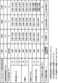
- the CPU 201 controls the operation of the turbo-molecular pump 100 and performs TMS control to operate the turbo-molecular pump 100 according to one of specifications 1 to 4 shown in FIG. 7 (operating specifications).
- the setting of the rated rotational speed of the motor 121 that rotationally drives the rotor blades 102 of the turbo-molecular pump 100 differs depending on the specifications.
- the rotation speed ⁇ 2 set as the rated rotation speed of the motor 121 in specification 2 and the rotation speed ⁇ 3 set as the rated rotation speed of the motor 121 in specification 3 are the same as the rated rotation speed of the motor 121 in specification 1.
- the rotation speed ⁇ 4 set as the rated rotation speed of the motor 121 in Specification 4 is smaller than the rotation speed ⁇ 1.
- the control mode of the TMS control executed by the CPU 201 and the TMS set temperature, which is the target temperature in the TMS control, also differ according to the specifications.
- TMS control is not executed and the TMS set temperature is not set.
- the solenoid valve that controls the flow of cooling water to the water-cooled pipe 149 is always open, and cooling by the water-cooled pipe 149 is always performed.
- TMS control is performed in the TMS standard mode with the temperature T2 as the TMS set temperature.
- TMS control is performed in the TMS first special mode in which the temperature T3, which is higher than the temperature T2, is set as the TMS set temperature.
- TMS control is performed in the TMS second special mode in which temperature T4, which is higher than temperature T3, is set as the TMS set temperature.
- TMS control is not performed, neither heating control by the heater nor cooling control by the water cooling pipe 149 is performed.
- TMS control of the TMS standard mode, the TMS first special mode, or the TMS second special mode is performed, heating control by the heater and cooling control by the water cooling pipe 149 are performed.
- the control mode of the TMS control is different, so whether or not the heating control by the heater is executed or whether the cooling control by the water cooling pipe 149 is executed or not is different.
- the temperature inside the pump which is the temperature of the passage, depends on the rated rotation speed of the motor 121 and the TMS set temperature, and differs depending on the specifications. Specifically, in specifications 2 and 3, the pumping speed, compression ratio, and ultimate pressure of the turbomolecular pump 100 are equivalent to those in specification 1, which is the standard, while in specification 4, they are lower than in specification 1.
- the permissible flow rate of the turbomolecular pump 100 is lower than the specification 1 in the specification 2, lower than the specification 2 in the specification 3, lower than the specification 2 and higher than the specification 3 in the specification 4.
- the pump internal temperature TP2 in specification 2 is higher than the temperature TP1, which is the pump internal temperature in specification 1
- the pump internal temperature TP3 in specification 3 is higher than the pump internal temperature TP2 in specification 2
- the pump internal temperature TP4 in specification 4 is Higher than the pump internal temperature TP3 in specification 3.
- the turbo molecular pump 100 will be described as having four types of specifications 1 to 4, but this is only an example, and the turbo molecular pump 100 may have three or less specifications. There may be, or there may be five or more. Moreover, the setting of the specifications shown in FIG. 7 is merely an example, and the specifications of the turbo-molecular pump 100 can be set arbitrarily.
- the storage unit 202 provided in the control device 200 pre-stores specification information indicating settings relating to the operating state of the turbo-molecular pump 100 in specifications 1 to 4 shown in FIG.
- the CPU 201 controls the operation of the turbo-molecular pump 100 according to the specification information, and performs TMS control to operate the turbo-molecular pump 100 according to any one of specifications 1 to 4.
- FIG. Specifically, the CPU 201 identifies the rated rotational speed of the motor 121 corresponding to the currently set specifications by referring to the specification information, and transmits a command signal to the turbomolecular pump 100 via the wired communication unit 203. By doing so, the control parameters of the turbo-molecular pump 100 are set so that the rated rotation speed of the motor 121 becomes the specified rated rotation speed.
- the CPU 201 identifies the control mode of TMS control and the TMS set temperature corresponding to the currently set specifications by referring to the specification information, and sets the identified TMS set temperature as the target temperature. TMS control of the control mode is performed
- the remote control device 300 when the remote control device 300 receives an instruction from the user to change the specifications of the turbo-molecular pump 100 to the specifications specified by the user, the remote control device 300 changes the specifications of the turbo-molecular pump 100 to the specifications specified by the user.
- a setting change command signal which is a command signal to instruct, is transmitted to the control device 200 by remote communication.
- the remote communication unit 204 receives a setting change command signal from the remote control device 300
- the CPU 201 controls the turbo molecular pump 100, which is an example of settings related to the operating state of the turbo molecular pump 100, based on the received setting change command signal. change the specifications (operation specifications).
- the CPU 201 when the remote communication unit 204 receives the setting change command signal, the CPU 201 refers to the above-described specification information to correspond to the changed specifications of the turbo-molecular pump 100 indicated by the setting change command signal. Identify the rated rotational speed of the motor 121 . Then, the CPU 201 transmits a command signal to the turbo-molecular pump 100 via the wired communication unit 203, and changes the control parameters of the turbo-molecular pump 100 so that the rated rotation speed of the motor 121 is set to the currently set turbo. The rated rotation speed corresponding to the specification of the molecular pump 100 is changed to the rated rotation speed corresponding to the specified changed specification of the turbo-molecular pump 100 .
- the CPU 201 refers to the specification information to perform TMS control corresponding to the changed specification of the turbo-molecular pump 100 indicated by the setting change command signal. Specify mode and TMS set temperature. Then, the CPU 201 changes the control mode of the TMS control from the control mode corresponding to the currently set specifications of the turbo-molecular pump 100 to the control mode corresponding to the specified changed specifications of the turbo-molecular pump 100. At the same time, the TMS set temperature is changed from the TMS set temperature corresponding to the specification of the turbo-molecular pump 100 currently set to the TMS set temperature corresponding to the specified changed specification of the turbo-molecular pump 100 .
- the CPU 201 functions as a specification change device for changing the operation specifications of the turbo-molecular pump 100 based on the received setting change command signal.
- the control mode and TMS set temperature of TMS control which are settings related to the operation of the heater and water cooling pipe 149, are changed.
- the CPU 201 When the remote communication unit 204 receives a setting change command signal while the turbo-molecular pump 100 is operating and TMS control is being performed, the CPU 201 does not stop the operation of the turbo-molecular pump 100 and , change the specifications of the turbo-molecular pump 100 based on the received setting change command signal without stopping the TMS control, and change the control mode of the TMS control and the TMS set temperature. Specifically, when the remote communication unit 204 receives a setting change command signal while the turbo-molecular pump 100 is operating, the CPU 201 transmits the command signal to the turbo-molecular pump 100 via the wired communication unit 203.
- the rated rotation speed of the motor 121 can be changed from the currently set rated rotation speed to the rated rotation speed corresponding to the changed specifications of the turbo-molecular pump 100 without stopping the rotational driving of the rotor blades 102 by the motor 121.
- Change to speed when the remote communication unit 204 receives a setting change command signal while performing TMS control, the CPU 201 changes the control mode of the TMS control to the currently set control mode without stopping the TMS control. to the control mode corresponding to the specifications of the turbo-molecular pump 100 after the change, and the TMS set temperature is changed from the currently set TMS set temperature to the TMS set temperature corresponding to the specifications of the turbo-molecular pump 100 after the change. change.
- the remote control device 300 includes a CPU 301, a storage unit 302, a remote communication unit 303, an output interface 304, an operation unit 305, and a system bus 306, as shown in FIG.
- the CPU 301 executes various processes according to the programs and data stored in the storage unit 302.
- the storage unit 302 includes a non-volatile memory (not shown) such as ROM, flash memory, EPROM, etc., and non-volatilely stores programs and data used by the CPU 301 to execute various processes. Furthermore, the storage unit 302 has a RAM (not shown) that functions as a work area for the CPU 301 .
- the remote communication unit 303 performs remote communication with an external device of the remote control device 300 to transmit and receive signals. Specifically, the remote communication unit 303 includes a remote I/O unit (not shown), and uses the remote I/O unit to communicate with the control device 200 via a communication network. By communicating, signals are sent and received. Remote communication unit 303 transmits a command signal to control device 200 by performing remote communication with control device 200 .
- the remote communication unit 303 is an example of remote signal transmission means.
- the output interface 304 presents information regarding the operating state of the turbomolecular pump 100 to the user.
- the output interface 304 is provided with an LCD panel (not shown), on which a message indicating the setting of the operating specifications of the turbo-molecular pump 100, a message indicating the current operating state of the turbo-molecular pump 100, Various images for notifying the operating state of the turbo-molecular pump 100, such as an error message for notifying an operational abnormality of the turbo-molecular pump 100, are displayed.
- An operation unit 305 includes operators such as a keyboard, a touch panel, and operation switches, and receives input of various instructions from the user in accordance with user's operations on the operators.
- a system bus 306 is a transmission path for commands and data, and interconnects the CPU 301 to the operation unit 305 .
- the functions of the CPU 301 will be described in detail below.
- the CPU 301 remotely controls the turbomolecular pump 100 according to instructions input by the user by operating the operation unit 305 .
- the CPU 301 causes the remote communication unit 303 to transmit a command signal corresponding to the instruction received by the operation unit 305 to the control device 200, and instructs the control device 200 to control the operation of the turbomolecular pump 100 according to the received command signal.
- the turbomolecular pump 100 is remotely controlled by turning on.
- the CPU 301 is an example of remote control means.
- the CPU 301 transmits a command signal for instructing the start-up of the turbo-molecular pump 100 to the remote communication unit 303 to the control device 200 .
- the CPU 301 causes the remote communication unit 303 to transmit a command signal instructing to stop the turbo-molecular pump 100 to the control device 200 .
- the CPU 301 When the user operates the operation unit 305 to input an instruction to confirm the setting of the operation specifications of the turbomolecular pump 100, the CPU 301 causes the remote communication unit 303 to transmit a command signal instructing confirmation of the setting to the control device 200. .
- the control device 200 transmits a signal indicating the setting of the operation specifications of the turbomolecular pump 100 to the remote control device 300 in response to receiving the command signal, the CPU 301 transmits the signal via the remote communication unit 303.
- Receive and cause output interface 304 to present the settings to the user based on the signals received.
- the CPU 301 transmits a command signal instructing confirmation of the operation specifications to the remote communication unit 303 to the control device 200.
- the control device 200 transmits a signal indicating the current operating specifications of the turbomolecular pump 100 to the remote control device 300 in response to receiving the command signal
- the CPU 301 transmits the signal via the remote communication unit 303.
- Receive and cause output interface 304 to present the driving specification to the user based on the received signal.
- the CPU 301 instructs to change the specifications of the turbo-molecular pump 100 to the specifications specified by the user.
- the remote communication unit 303 transmits a setting change command signal, which is a command signal to change the setting, to the control device 200
- the control device 200 is caused to change the specifications of the turbo-molecular pump 100 based on the received setting change command signal.
- the user refers to the schedule of the processes performed in the chamber XR of the semiconductor manufacturing apparatus X, and operates the operation unit 305 to start the turbomolecular pump 100 at the timing when the processes performed in the chamber XR are switched. Instruct to switch specifications.
- a change in the specifications of the turbomolecular pump 100 will be described below with reference to the timing chart of FIG. 9 and taking as an example the case where Process 1 and Process 2 are performed in the chamber XR.
- process 1 it is assumed that gas A, gas B, and gas C are introduced into chamber XR by semiconductor manufacturing apparatus X as process gases.
- process 2 the semiconductor manufacturing apparatus X introduces gas D, gas E, and gas F into the chamber XR as process gases.
- the control device 200 causes the turbo-molecular pump 100 to start the operation according to the specification 2, which is the specification corresponding to the process 1, from the time 0 and starts the TMS control corresponding to the specification 2 will be used as an example. to explain.
- the control device 200 causes the motor 121 of the turbo-molecular pump 100 to start rotating at the rotation speed ⁇ 2, which is the rated rotation speed corresponding to the specification 2. Further, from time 0, the control device 200 starts TMS control in the TMS standard mode in which the temperature T2 is the TMS set temperature.
- the semiconductor manufacturing apparatus X starts introducing gas A at time t1, stops introducing gas A at time t2, starts introducing gas B, and stops introducing gas B at time t3.
- the introduction of gas C is started at time t4, and the introduction of gas C is stopped at time t4.
- the semiconductor manufacturing apparatus X starts introducing gas D at time t6 after time t4, stops introducing gas D at time t7, starts introducing gas E, and starts introducing gas E at time t8. It is assumed that the introduction of gas E is stopped, the introduction of gas F is started, and the introduction of gas F is stopped at time t9.
- the semiconductor manufacturing apparatus X starts introducing gas A at time t11 after time t9, stops introducing gas A, and starts introducing gas B at time t12. .
- the user operates remote control device 300 to An example of inputting an instruction to change the specification of the molecular pump 100 from specification 2, which is the currently set specification, to specification 3, which is the specification corresponding to process 2, will be described.
- the remote control device 300 outputs a setting change command signal for instructing the specification of the turbo-molecular pump 100 to be switched from the specification 2 to the specification 3, which is the specification specified by the user, in accordance with the user's instruction. 200.
- the control device 200 receives a setting change command signal from the remote control device 300, and changes the specification of the turbo-molecular pump 100 from specification 2 to specification 3. will be described as changing to
- control device 200 switches the specification of the turbo-molecular pump 100 from specification 2 to specification 3 without stopping the operation of the turbo-molecular pump 100 and without stopping the TMS control. Specifically, control device 200 identifies rotational speed ⁇ 3, which is the rated rotational speed corresponding to specification 3, by referring to the specification information stored in storage unit 202 . The control device 200 transmits a command signal to the turbo-molecular pump 100 to change the control parameters, thereby increasing the rated rotational speed of the motor 121 to the specified speed without stopping the rotation of the rotor blades 102 by the motor 121. 2 is changed from the rotational speed ⁇ 2, which is the rated rotational speed corresponding to 2, to the rotational speed ⁇ 3.
- the control device 200 specifies the TMS first special mode, which is the control mode of TMS control corresponding to specification 3, and the temperature T3, which is the TMS set temperature corresponding to specification 3. do. Then, the control device 200 changes the control mode of the TMS control from the TMS standard mode corresponding to the specification 2 to the TMS first special mode without stopping the TMS control, and changes the TMS set temperature to correspond to the specification 2. The temperature is changed from the temperature T2 to the temperature T3.
- the user operates remote control device 300 to An example of inputting an instruction to change the specification of the molecular pump 100 from specification 3, which is the currently set specification, to specification 2, which is the specification corresponding to process 1, will be described.
- the remote control device 300 outputs a setting change command signal for instructing the specification of the turbomolecular pump 100 to be switched from the specification 3 to the specification 2, which is the specification specified by the user, according to the user's instruction. 200.
- the control device 200 receives a setting change command signal from the remote control device 300, and changes the specification of the turbo-molecular pump 100 from specification 3 to specification 2. will be described as changing to
- the control device 200 switches the specification of the turbo-molecular pump 100 from specification 3 to specification 2 without stopping the operation of the turbo-molecular pump 100 and without stopping the TMS control. That is, the control device 200 transmits a command signal to the turbo-molecular pump 100 to change the control parameters, thereby increasing the rated rotational speed of the motor 121 to the specified speed without stopping the rotational driving of the rotor blades 102 by the motor 121.
- the rotation speed ⁇ 3, which is the rated rotation speed corresponding to Specification 2 is changed to the rotation speed ⁇ 2 corresponding to Specification 2.
- control device 200 changes the control mode of the TMS control from the TMS first special mode corresponding to the specification 3 to the TMS standard mode corresponding to the specification 2 without stopping the TMS control. is changed from temperature T3 corresponding to specification 3 to temperature T2 corresponding to specification 2.
- the turbo-molecular pump 100 provided in the vacuum pump 10 is configured to be operable under any of the specifications 1 to 4, and according to the control by the control device 200 provided in the vacuum pump 10, the specifications 1 to 4 Operates with any one of specifications 4.
- a vacuum pump of specification 1, a vacuum pump of specification 2, a vacuum pump of specification 3, and a vacuum pump of specification 4 are purchased in the factory where the semiconductor manufacturing apparatus X is installed. Compared to the case where the vacuum pump is stored, the purchase cost of the vacuum pump can be reduced, and the space required for storing the vacuum pump can be reduced.
- Such an advantage of the vacuum pump 10 according to the present invention becomes particularly remarkable when the semiconductor manufacturing apparatus X has a plurality of chambers XR and different types of processes are performed in each chamber.
- each chamber XR has different types of chambers operating according to specifications corresponding to the processes performed in each chamber XR. If you try to prepare a spare vacuum pump for replacement when the vacuum pump breaks down or you need to perform maintenance on the vacuum pump, you will need to prepare a spare vacuum pump of a different type for each chamber XR. must be prepared as a vacuum pump for each. Therefore, there is a risk that the user will be burdened with the cost of purchasing a large number of spare vacuum pumps and securing the space required to store a large number of spare vacuum pumps.
- the common pump of the present invention is a vacuum pump that can operate in each of the plurality of chambers XR provided in the semiconductor manufacturing apparatus X according to any specification among the specifications required for each process performed in each chamber XR.
- the spare vacuum pump 10 for one chamber XR can also be used as the spare vacuum pump 10 for the other chamber XR. Therefore, compared to the above example in which different types of vacuum pumps are prepared as backup vacuum pumps for each chamber XR, the number of vacuum pumps to be prepared as backup vacuum pumps can be reduced, and the purchase cost of vacuum pumps can be reduced. , the space required for storing the vacuum pump can be reduced.
- control device 200 when remote communication unit 204 receives a setting change command signal from remote control device 300, control device 200 changes the operating state of turbomolecular pump 100 based on the received setting change command signal.
- Change the specifications of the turbo-molecular pump 100 which is an example of settings related to .
- the user can go to the place where the vacuum pump 10 is installed and operate the control device 200 by operating the remote control device 300 installed at a place away from the vacuum pump 10.
- the specifications of the turbomolecular pump 100 can be changed without modification. Therefore, according to such a configuration, it is possible to reduce the work burden on the user.
- Such an advantage of the vacuum pump 10 according to the present invention becomes particularly remarkable when the semiconductor manufacturing apparatus X includes a plurality of chambers XR, and each chamber is equipped with the vacuum pump 10 as the above-described common pump. .
- the specifications of the vacuum pumps 10 attached to each of the plurality of chambers XR included in the semiconductor manufacturing apparatus X can be checked by the user going to the place where each vacuum pump 10 is installed and manually operating the controller 200. Therefore, if the specifications must be set according to the process performed in each chamber XR, the user's workload will be increased.
- the vacuum pump 10 is configured so that the specifications can be changed according to instructions input by the user by operating the remote control device 300, the user can go to the place where the vacuum pump 10 is installed and control it.
- the specifications of the vacuum pump 10 can be changed without operating the device 200 . Therefore, according to such a configuration, it is possible to reduce the work burden on the user.
- the control device 200 when the remote communication unit 204 receives a setting change command signal, the control device 200 changes the operation specifications of the turbo-molecular pump 100 based on the received setting change command signal.
- the control mode and TMS set temperature of TMS control which are settings related to the operation of the heater and water cooling pipe 149, are changed.
- the user can change the settings related to the operation of the specification changing device by operating the remote control device 300 without going to the place where the vacuum pump 10 is installed and operating the control device 200. , the operating specifications of the turbomolecular pump 100 can be changed. Therefore, according to such a configuration, it is possible to reduce the work burden on the user.
- the user operates the remote control device 300 to heat the base portion 129 as the specification changing device without going to the place where the vacuum pump 10 is installed and operating the control device 200. It is possible to change the temperature inside the turbo-molecular pump 100 as the operation specification of the turbo-molecular pump 100 by changing the settings related to the operation of the water cooling pipe 149 that cools the heater and the base portion 129 .
- the control device 200 controls the operation of the turbo-molecular pump 100 without stopping the operation. , changes the specifications of the turbo-molecular pump 100 based on the received setting change command signal. According to such a configuration, when the operating turbo-molecular pump 100 is temporarily stopped, the specification of the turbo-molecular pump 100 is changed, and the operation of the turbo-molecular pump 100 is restarted after the specification change is completed. Compared to , the work time can be shortened and the user's convenience can be improved.
- Such an advantage of the vacuum pump 10 according to the present invention is particularly remarkable when the semiconductor manufacturing apparatus X performs multiple processes within the chamber XR, that is, when multiple processes are performed within one chamber XR. .
- the semiconductor manufacturing apparatus X can be made smaller than when each process is performed in different chambers XR. After performing a process, the time required to move the semiconductor substrate to the chamber XR where another process is performed can be eliminated, thus reducing the time required to perform the process.
- a specific example of performing a plurality of processes inside one chamber XR there is a case where a process for etching a semiconductor substrate and a film forming process for a semiconductor substrate are performed inside one chamber XR. mentioned.
- the control device 200 provided in the vacuum pump 10 receives a setting change command signal from the remote control device 300 while the turbo molecular pump 100 provided in the vacuum pump 10 is operating, the turbo Without stopping the operation of the molecular pump 100, the specification of the turbo molecular pump 100 is changed based on the received setting change command signal.
- the specifications of the vacuum pump 10 attached to the chamber XR are changed according to the first process.
- the specification can be changed to the specification according to the second process without stopping the operation of the vacuum pump 10 .
- the turbo-molecular pump 100 that has been operating with the specifications corresponding to the first process is temporarily stopped, and then the specifications of the turbo-molecular pump 100 are changed to the specifications corresponding to the second process, and the specification change is completed.
- the work time can be shortened and the user's convenience can be improved.
- control device 200 when remote communication unit 204 receives a setting change command signal while TMS control is being performed, control device 200 does not stop TMS control. Based on the signal, the specifications of the turbomolecular pump 100 are changed, and the control mode of TMS control and the TMS set temperature are changed. According to such a configuration, the TMS control being executed is temporarily stopped, the specifications of the turbo-molecular pump 100 are changed, the control mode of the TMS control and the TMS set temperature are changed, and after the specification change is completed, Compared to restarting TMS control, the work time can be shortened and user convenience can be improved.
- the vacuum pump 10 includes the turbo-molecular pump 100 that exhausts gas inside the semiconductor manufacturing apparatus X, which is an example of an evacuation target apparatus, and the control device 200 that controls the turbo-molecular pump 100.
- the control device 200 includes a remote communication unit 204 that receives a command signal from a remote control device 300 that remotely controls the turbomolecular pump 100, and operates the turbomolecular pump 100 based on the setting change command signal received by the remote communication unit 204.
- the specifications of the turbomolecular pump 100 which is an example of settings related to specifications, are changed. According to such a configuration, it is possible to reduce the workload of the user and field service engineers.
- the control device 200 When the remote communication unit 204 receives a setting change command signal from the remote control device 300 while the turbo-molecular pump 100 is operating, the control device 200 changes the setting without stopping the operation of the turbo-molecular pump 100.
- the specifications of the turbomolecular pump 100 are changed based on the command signal. According to such a configuration, user convenience can be improved.
- the vacuum pump 10 includes a heater for heating the turbo-molecular pump 100 and a water cooling pipe 149 for cooling the turbo-molecular pump 100 as a specification changing device for changing the operation specification of the turbo-molecular pump 100 .
- the control device 200 Based on the setting change command signal received by the remote communication unit 204, the control device 200 changes the setting regarding the operation of the specification changing device. According to such a configuration, it is possible to reduce the workload of the user and field service engineers.
- the remote control device 300 includes a remote communication unit 303 that is provided in the vacuum pump 10 and transmits a command signal to the control device 200 that controls the turbomolecular pump 100 that exhausts the gas inside the semiconductor manufacturing apparatus X, and a remote communication unit. and a CPU 301 that remotely controls the turbomolecular pump 100 by causing the controller 303 to transmit a command signal to the control device 200 .
- the CPU 301 causes the remote communication unit 303 to transmit a setting change command signal to the control device 200, thereby causing the control device 200 to change the specifications of the turbomolecular pump 100 based on the received setting change command signal. According to such a configuration, it is possible to reduce the workload of the user and field service engineers.
- the control device 200 which is an example of a specification setting device, is a device to be controlled that can change the operation specification of the turbo-molecular pump 100 when the remote communication unit 204 receives a setting change command signal.
- the setting related to the operation specification of the turbo-molecular pump 100 may be changed based on the setting change command signal.
- the control device 200 may be configured to change the settings related to the operation specifications of the turbo-molecular pump 100 by changing the rotation speed of the motor 121, which is an example of a device to be controlled.
- the rotational speed of the motor 121 is an example of the operating specifications of the motor 121 .
- the control device 200 is provided separately from the turbo-molecular pump 100 and placed at a location away from the turbo-molecular pump 100, and the control device 200 operates in the manual operation control mode described above.
- the CPU 201 changes the operating specifications (eg, rotation speed) of the device to be controlled (eg, the motor 121).
- the specifications of the turbo-molecular pump 100 may be changed. With such a configuration, convenience for the user can be improved.
- the control device 200 changes the specifications of the turbo-molecular pump 100 based on the setting change command signal received from the remote control device 300, but this is only an example.
- the control device 200 can change any settings related to the operation specifications of the turbomolecular pump 100 based on the command signal received from the remote control device 300 .
- the control device 200 may be configured to change only the rotation speed of the motor 121 based on the command signal received from the remote control device 300 .
- a modification in which the control device 200 changes only the rotation speed of the motor 121 based on the command signal received from the remote control device 300 will be described below.
- the turbomolecular pump 100 includes a rotor blade temperature sensor (not shown) that measures the temperature of the rotor blades 102 .
- the control device 200 receives the detection signal output from the rotor blade temperature sensor via the wired communication unit 203, and transmits the rotor blade temperature signal indicating the temperature of the rotor blade 102 to the remote control device based on the received detection signal. 300.
- the remote controller 300 constantly monitors the temperature of the rotor blade 102 based on the rotor blade temperature signal received from the controller 200 .
- the remote control device 300 controls the maximum set rotation that can be achieved for the motor 121 based on the difference between the current temperature of the rotor blade 102 indicated by the rotor blade temperature signal received from the control device 200 and the preset set temperature. Calculate speed.
- the remote control device 300 transmits to the control device 200 a rotation speed change command signal instructing to rotate the motor 121 at the calculated set rotation speed, thereby instructing the control device 200 to rotate the motor 121 at the set rotation speed.
- Control to rotate The control device 200 determines the difference between the calculated set rotation speed indicated by the rotation speed change command signal received from the remote control device 300 and the current rotation speed of the motor 121 indicated by the detection signal of the rotation speed sensor included in the motor 121.
- the motor 121 By driving the motor 121 based on the above, the motor 121 is rotated at the calculated set rotational speed. According to such a configuration, the rotation speed of the motor 121 can be increased while the temperature of the rotor blades 102 is maintained within the restricted range, and the exhaust performance of the turbo-molecular pump 100 can be maximized.
- the remote control device 300 When the current temperature of the rotor blade 102 indicated by the rotor blade temperature signal received from the controller 200 exceeds a preset allowable value, the remote control device 300 provides a command signal to instruct the rotation speed of the motor 121 to be reduced. is sent to the control device 200 to cause the control device 200 to reduce the rotational speed of the motor 121 and reduce the collision frequency between the rotor blades 102 and gas molecules. With such a configuration, the temperature of the rotor blade 102 can be lowered, and deterioration of the rotor blade 102 due to heat can be suppressed.
- the existing vacuum pump control device and remote control device can be made to function as the vacuum pump control device and remote control device according to the present invention. That is, the program for realizing each function of the vacuum pump control device and remote control device according to the present invention is applied so that a processor such as a CPU that controls the existing vacuum pump control device and remote control device can be executed. By doing so, the existing vacuum pump control device and remote control device can function as the vacuum pump control device and remote control device according to the present invention.
- the method of applying such a program is arbitrary.
- the program can be applied by storing it in a computer-readable storage medium such as a flexible disk, CD (Compact Disc)-ROM, DVD (Digital Versatile Disc)-ROM, and memory card.
- a program can be superimposed on a carrier wave and applied via a communication medium such as the Internet.
- the program may be posted and distributed on a bulletin board (BBS: Bulletin Board System) on a communication network.
- BSS Bulletin Board System
- the above processing may be executed by starting this program and executing it in the same manner as other application programs under the control of an OS (Operating System).
- OS Operating System
Landscapes
- Engineering & Computer Science (AREA)
- Mechanical Engineering (AREA)
- General Engineering & Computer Science (AREA)
- Physics & Mathematics (AREA)
- General Physics & Mathematics (AREA)
- Automation & Control Theory (AREA)
- Computer Networks & Wireless Communication (AREA)
- Thermal Sciences (AREA)
- Non-Positive Displacement Air Blowers (AREA)
- Valves And Accessory Devices For Braking Systems (AREA)
Abstract
Description
排気対象装置の内部の気体を排気するポンプ本体と、
前記ポンプ本体に対する制御を行う制御装置と、
を備えた真空ポンプであって、
前記制御装置は、
前記ポンプ本体をリモート制御するリモート制御装置から指令信号を受信するリモート信号受信手段を備え、
前記リモート信号受信手段が受信した前記指令信号に基づき、前記ポンプ本体の運転仕様に関わる設定を変更することを特徴とする。
前記制御装置は、前記ポンプ本体が動作しているときに、前記リモート信号受信手段が前記指令信号を前記リモート制御装置から受信した場合、前記ポンプ本体の動作を停止することなく、前記指令信号に基づき前記設定を変更するようにしてもよい。
前記ポンプ本体の運転仕様を変更する仕様変更デバイスをさらに備え、
前記制御装置は、前記リモート信号受信手段が受信した前記指令信号に基づき、前記仕様変更デバイスの動作に関する設定を変更するようにしてもよい。
前記仕様変更デバイスは、前記ポンプ本体を加熱する加熱手段又は前記ポンプ本体を冷却する冷却手段であるようにしてもよい。
排気対象装置の内部の気体を排気するポンプ本体を有する真空ポンプであって、
前記ポンプ本体が有する運転仕様を変更可能な制御対象デバイスと、
前記制御対象デバイスの運転仕様を変更することにより、前記ポンプ本体の運転仕様に関わる設定を変更する仕様設定デバイスとを備えたことを特徴とする。
排気対象装置の内部の気体を排気するポンプ本体に対する制御を行う制御手段と、
前記ポンプ本体をリモート制御するリモート制御装置から指令信号を受信するリモート信号受信手段と、
を備えた真空ポンプの制御装置であって、
前記制御手段は、前記リモート信号受信手段が受信した前記指令信号に基づき、前記ポンプ本体の運転仕様に関わる設定を変更することを特徴とする。
排気対象装置の内部の気体を排気するポンプ本体に対する制御を行う制御装置へ指令信号を送信するリモート信号送信手段と、
前記リモート信号送信手段に前記指令信号を前記制御装置へ送信させることにより、前記ポンプ本体をリモート制御するリモート制御手段と、
を備えたリモート制御装置であって、
前記リモート制御手段は、前記リモート信号送信手段に前記指令信号を前記制御装置へ送信させることにより、前記制御装置に、受信した前記指令信号に基づき、前記ポンプ本体の運転仕様に関わる設定を変更させることを特徴とする。
10 真空ポンプ
11 接続ケーブル
100 ターボ分子ポンプ
102、102a、102b、102c 回転翼
121 モータ
149 水冷管
200 制御装置
201、301 CPU
202、302 記憶部
203 有線通信部
204、303 リモート通信部
205、304 出力インタフェース
206、305 操作部
207、306 システムバス
300 リモート制御装置
X 半導体製造装置
XR チャンバ
Claims (7)
- 排気対象装置の内部の気体を排気するポンプ本体と、
前記ポンプ本体に対する制御を行う制御装置と、
を備えた真空ポンプであって、
前記制御装置は、
前記ポンプ本体をリモート制御するリモート制御装置から指令信号を受信するリモート信号受信手段を備え、
前記リモート信号受信手段が受信した前記指令信号に基づき、前記ポンプ本体の運転仕様に関わる設定を変更することを特徴とする真空ポンプ。 - 前記制御装置は、前記ポンプ本体が動作しているときに、前記リモート信号受信手段が前記指令信号を前記リモート制御装置から受信した場合、前記ポンプ本体の動作を停止することなく、前記指令信号に基づき前記設定を変更することを特徴とする請求項1に記載の真空ポンプ。
- 前記ポンプ本体の運転仕様を変更する仕様変更デバイスをさらに備え、
前記制御装置は、前記リモート信号受信手段が受信した前記指令信号に基づき、前記仕様変更デバイスの動作に関する設定を変更することを特徴とする請求項1又は2に記載の真空ポンプ。 - 前記仕様変更デバイスは、前記ポンプ本体を加熱する加熱手段又は前記ポンプ本体を冷却する冷却手段であることを特徴とする請求項3に記載の真空ポンプ。
- 排気対象装置の内部の気体を排気するポンプ本体を有する真空ポンプであって、
前記ポンプ本体が有する運転仕様を変更可能な制御対象デバイスと、
前記制御対象デバイスの運転仕様を変更することにより、前記ポンプ本体の運転仕様に関わる設定を変更する仕様設定デバイスとを備えたことを特徴とする真空ポンプ。 - 排気対象装置の内部の気体を排気するポンプ本体に対する制御を行う制御手段と、
前記ポンプ本体をリモート制御するリモート制御装置から指令信号を受信するリモート信号受信手段と、
を備えた真空ポンプの制御装置であって、
前記制御手段は、前記リモート信号受信手段が受信した前記指令信号に基づき、前記ポンプ本体の運転仕様に関わる設定を変更することを特徴とする真空ポンプの制御装置。 - 排気対象装置の内部の気体を排気するポンプ本体に対する制御を行う制御装置へ指令信号を送信するリモート信号送信手段と、
前記リモート信号送信手段に前記指令信号を前記制御装置へ送信させることにより、前記ポンプ本体をリモート制御するリモート制御手段と、
を備えたリモート制御装置であって、
前記リモート制御手段は、前記リモート信号送信手段に前記指令信号を前記制御装置へ送信させることにより、前記制御装置に、受信した前記指令信号に基づき、前記ポンプ本体の運転仕様に関わる設定を変更させることを特徴とするリモート制御装置。
Priority Applications (5)
| Application Number | Priority Date | Filing Date | Title |
|---|---|---|---|
| IL305255A IL305255A (en) | 2021-03-19 | 2022-03-11 | Vacuum pump, vacuum pump controller and remote controller |
| US18/279,349 US20240167484A1 (en) | 2021-03-19 | 2022-03-11 | Vacuum pump, vacuum pump controller, and remote controller |
| KR1020237028795A KR20230159383A (ko) | 2021-03-19 | 2022-03-11 | 진공 펌프, 진공 펌프의 제어 장치 및 리모트 제어 장치 |
| EP22771306.2A EP4310338A1 (en) | 2021-03-19 | 2022-03-11 | Vacuum pump, vacuum pump control device, and remote control device |
| CN202280017568.7A CN116888369A (zh) | 2021-03-19 | 2022-03-11 | 真空泵、真空泵的控制装置及远程控制装置 |
Applications Claiming Priority (2)
| Application Number | Priority Date | Filing Date | Title |
|---|---|---|---|
| JP2021046536A JP2022145225A (ja) | 2021-03-19 | 2021-03-19 | 真空ポンプ、真空ポンプの制御装置及びリモート制御装置 |
| JP2021-046536 | 2021-03-19 |
Publications (1)
| Publication Number | Publication Date |
|---|---|
| WO2022196558A1 true WO2022196558A1 (ja) | 2022-09-22 |
Family
ID=83320338
Family Applications (1)
| Application Number | Title | Priority Date | Filing Date |
|---|---|---|---|
| PCT/JP2022/010896 WO2022196558A1 (ja) | 2021-03-19 | 2022-03-11 | 真空ポンプ、真空ポンプの制御装置及びリモート制御装置 |
Country Status (7)
| Country | Link |
|---|---|
| US (1) | US20240167484A1 (ja) |
| EP (1) | EP4310338A1 (ja) |
| JP (1) | JP2022145225A (ja) |
| KR (1) | KR20230159383A (ja) |
| CN (1) | CN116888369A (ja) |
| IL (1) | IL305255A (ja) |
| WO (1) | WO2022196558A1 (ja) |
Citations (6)
| Publication number | Priority date | Publication date | Assignee | Title |
|---|---|---|---|---|
| JP2007303420A (ja) * | 2006-05-12 | 2007-11-22 | Shimadzu Corp | ターボ分子ポンプおよびターボ分子ポンプシステム |
| JP2009009786A (ja) * | 2007-06-27 | 2009-01-15 | Shimadzu Corp | 質量分析装置 |
| JP2010059908A (ja) * | 2008-09-05 | 2010-03-18 | Shimadzu Corp | ポンプシステム |
| JP5782378B2 (ja) | 2009-08-21 | 2015-09-24 | エドワーズ株式会社 | 真空ポンプ |
| WO2019188732A1 (ja) * | 2018-03-30 | 2019-10-03 | エドワーズ株式会社 | 真空ポンプ |
| WO2021060003A1 (ja) * | 2019-09-27 | 2021-04-01 | エドワーズ株式会社 | 真空ポンプ及び真空ポンプの付属ユニット |
-
2021
- 2021-03-19 JP JP2021046536A patent/JP2022145225A/ja active Pending
-
2022
- 2022-03-11 CN CN202280017568.7A patent/CN116888369A/zh active Pending
- 2022-03-11 KR KR1020237028795A patent/KR20230159383A/ko unknown
- 2022-03-11 WO PCT/JP2022/010896 patent/WO2022196558A1/ja active Application Filing
- 2022-03-11 IL IL305255A patent/IL305255A/en unknown
- 2022-03-11 US US18/279,349 patent/US20240167484A1/en active Pending
- 2022-03-11 EP EP22771306.2A patent/EP4310338A1/en active Pending
Patent Citations (6)
| Publication number | Priority date | Publication date | Assignee | Title |
|---|---|---|---|---|
| JP2007303420A (ja) * | 2006-05-12 | 2007-11-22 | Shimadzu Corp | ターボ分子ポンプおよびターボ分子ポンプシステム |
| JP2009009786A (ja) * | 2007-06-27 | 2009-01-15 | Shimadzu Corp | 質量分析装置 |
| JP2010059908A (ja) * | 2008-09-05 | 2010-03-18 | Shimadzu Corp | ポンプシステム |
| JP5782378B2 (ja) | 2009-08-21 | 2015-09-24 | エドワーズ株式会社 | 真空ポンプ |
| WO2019188732A1 (ja) * | 2018-03-30 | 2019-10-03 | エドワーズ株式会社 | 真空ポンプ |
| WO2021060003A1 (ja) * | 2019-09-27 | 2021-04-01 | エドワーズ株式会社 | 真空ポンプ及び真空ポンプの付属ユニット |
Also Published As
| Publication number | Publication date |
|---|---|
| US20240167484A1 (en) | 2024-05-23 |
| IL305255A (en) | 2023-10-01 |
| JP2022145225A (ja) | 2022-10-03 |
| EP4310338A1 (en) | 2024-01-24 |
| KR20230159383A (ko) | 2023-11-21 |
| CN116888369A (zh) | 2023-10-13 |
Similar Documents
| Publication | Publication Date | Title |
|---|---|---|
| EP2469096B1 (en) | Vacuum pump | |
| JP2005083316A (ja) | モータ制御システム及び該モータ制御システムを搭載した真空ポンプ | |
| WO2019239934A1 (ja) | 真空ポンプ及び温度制御装置 | |
| WO2022196558A1 (ja) | 真空ポンプ、真空ポンプの制御装置及びリモート制御装置 | |
| US20220333607A1 (en) | Vacuum pump and accessory unit of vacuum pump | |
| WO2022186076A1 (ja) | 真空ポンプ、及び、真空排気装置 | |
| WO2022264925A1 (ja) | 真空ポンプ | |
| WO2022196559A1 (ja) | 真空ポンプおよび排気システム | |
| WO2023027084A1 (ja) | 真空ポンプおよび固定部品 | |
| WO2022220197A1 (ja) | ターボ分子ポンプ | |
| WO2022163341A1 (ja) | 真空ポンプ及びスペーサ | |
| WO2023037985A1 (ja) | 真空ポンプ及び真空ポンプの熱移動抑制部材 | |
| JP2023160495A (ja) | 真空ポンプ、制御装置および制御方法 | |
| WO2023095851A1 (ja) | 真空ポンプ及び制御装置 | |
| WO2023106154A1 (ja) | 真空ポンプおよび良熱伝導性部品 | |
| WO2022186075A1 (ja) | 真空ポンプ | |
| WO2022255202A1 (ja) | 真空ポンプ、スペーサ及びケーシング | |
| WO2023171566A1 (ja) | 真空ポンプ | |
| WO2022145292A1 (ja) | 真空ポンプ及び制御装置 | |
| JP2005094852A (ja) | モータ制御システム及び該モータ制御システムを搭載した真空ポンプ | |
| JP2022156223A (ja) | 真空ポンプ |
Legal Events
| Date | Code | Title | Description |
|---|---|---|---|
| 121 | Ep: the epo has been informed by wipo that ep was designated in this application |
Ref document number: 22771306 Country of ref document: EP Kind code of ref document: A1 |
|
| WWE | Wipo information: entry into national phase |
Ref document number: 305255 Country of ref document: IL |
|
| WWE | Wipo information: entry into national phase |
Ref document number: 202280017568.7 Country of ref document: CN |
|
| WWE | Wipo information: entry into national phase |
Ref document number: 18279349 Country of ref document: US |
|
| WWE | Wipo information: entry into national phase |
Ref document number: 2022771306 Country of ref document: EP |
|
| NENP | Non-entry into the national phase |
Ref country code: DE |
|
| ENP | Entry into the national phase |
Ref document number: 2022771306 Country of ref document: EP Effective date: 20231019 |
|
| WWE | Wipo information: entry into national phase |
Ref document number: 11202306216Y Country of ref document: SG |