WO2022196456A1 - 駆動装置 - Google Patents
駆動装置 Download PDFInfo
- Publication number
- WO2022196456A1 WO2022196456A1 PCT/JP2022/010102 JP2022010102W WO2022196456A1 WO 2022196456 A1 WO2022196456 A1 WO 2022196456A1 JP 2022010102 W JP2022010102 W JP 2022010102W WO 2022196456 A1 WO2022196456 A1 WO 2022196456A1
- Authority
- WO
- WIPO (PCT)
- Prior art keywords
- motor
- connector
- board
- fixed
- frame
- Prior art date
- Legal status (The legal status is an assumption and is not a legal conclusion. Google has not performed a legal analysis and makes no representation as to the accuracy of the status listed.)
- Ceased
Links
Images


Classifications
-
- H—ELECTRICITY
- H02—GENERATION; CONVERSION OR DISTRIBUTION OF ELECTRIC POWER
- H02K—DYNAMO-ELECTRIC MACHINES
- H02K11/00—Structural association of dynamo-electric machines with electric components or with devices for shielding, monitoring or protection
- H02K11/30—Structural association with control circuits or drive circuits
- H02K11/33—Drive circuits, e.g. power electronics
-
- H—ELECTRICITY
- H02—GENERATION; CONVERSION OR DISTRIBUTION OF ELECTRIC POWER
- H02K—DYNAMO-ELECTRIC MACHINES
- H02K5/00—Casings; Enclosures; Supports
- H02K5/04—Casings or enclosures characterised by the shape, form or construction thereof
- H02K5/22—Auxiliary parts of casings not covered by groups H02K5/06-H02K5/20, e.g. shaped to form connection boxes or terminal boxes
- H02K5/225—Terminal boxes or connection arrangements
-
- B—PERFORMING OPERATIONS; TRANSPORTING
- B62—LAND VEHICLES FOR TRAVELLING OTHERWISE THAN ON RAILS
- B62D—MOTOR VEHICLES; TRAILERS
- B62D5/00—Power-assisted or power-driven steering
- B62D5/04—Power-assisted or power-driven steering electrical, e.g. using an electric servo-motor connected to, or forming part of, the steering gear
-
- H—ELECTRICITY
- H02—GENERATION; CONVERSION OR DISTRIBUTION OF ELECTRIC POWER
- H02K—DYNAMO-ELECTRIC MACHINES
- H02K11/00—Structural association of dynamo-electric machines with electric components or with devices for shielding, monitoring or protection
- H02K11/0094—Structural association with other electrical or electronic devices
-
- H—ELECTRICITY
- H02—GENERATION; CONVERSION OR DISTRIBUTION OF ELECTRIC POWER
- H02K—DYNAMO-ELECTRIC MACHINES
- H02K9/00—Arrangements for cooling or ventilating
- H02K9/22—Arrangements for cooling or ventilating by solid heat conducting material embedded in, or arranged in contact with, the stator or rotor, e.g. heat bridges
-
- H—ELECTRICITY
- H02—GENERATION; CONVERSION OR DISTRIBUTION OF ELECTRIC POWER
- H02K—DYNAMO-ELECTRIC MACHINES
- H02K2211/00—Specific aspects not provided for in the other groups of this subclass relating to measuring or protective devices or electric components
- H02K2211/03—Machines characterised by circuit boards, e.g. pcb
Definitions
- the present disclosure relates to a driving device.
- Patent Document 1 a housing integrally formed with a connector is fixed to an axial end face of a frame by means of screws or the like.
- An object of the present disclosure is to provide a driving device capable of improving the degree of design freedom.
- a drive device of the present disclosure includes a motor, a motor frame, a control unit, an extension member, and a cover.
- a motor includes a motor case having a tubular portion, a stator fixed to the motor case, motor windings wound around the stator, a rotor provided to be rotatable relative to the stator, and a shaft rotating integrally with the rotor. have.
- the motor frame is provided on one side of the cylindrical portion in the axial direction.
- the control unit has at least one board and a connector unit, and is arranged on one side of the motor in the axial direction. On the board, electronic components related to control of energization to the motor windings are mounted.
- the connector unit has at least one connector erected from the base portion with a frontage facing outward in the axial direction of the motor.
- the extension member is fixed to the motor case.
- the cover has a hole through which the connector is inserted and is fixed to the expansion member.
- the expansion member is formed to extend to the outside of the projection area in which the cylindrical portion of the motor case is projected in the axial direction.
- control unit can be extended to the outside of the projection area of the cylindrical portion of the motor case, so a large board mounting area and connector unit frontage area can be secured, and the degree of freedom in design can be increased.
- FIG. 1 is a schematic configuration diagram showing a steering system according to the first embodiment
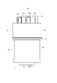
- FIG. 2 is a side view showing the driving device according to the first embodiment
- 3 is a view in the direction of arrow III in FIG. 2
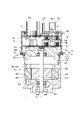
- FIG. 4 is a cross-sectional view taken along line IV-IV of FIG.
- FIG. 5 is a cross-sectional view taken along line VV in FIG.
- FIG. 6 is an exploded perspective view of the driving device according to the first embodiment
- FIG. 7 is an exploded perspective view of the driving device according to the first embodiment
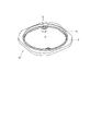
- FIG. 8 is a perspective view of an expansion member according to the first embodiment
- FIG. 9 is a perspective view of an expansion member according to the first embodiment
- FIG. 10 is a plan view of the expansion member according to the first embodiment
- FIG. 11 is a cross-sectional view taken along line XI-AO-XI in FIG.
- FIG. 12 is an enlarged view of the XII section of FIG. 11
- FIG. 13 is an enlarged view of section XIII in FIG. 11,
- 14 is a plan view showing a state in which the expansion member according to the first embodiment is assembled to the motor case
- FIG. FIG. 15 is a sectional view showing the motor and motor frame according to the second embodiment.
- FIGS. 1 to 14 A driving device according to a first embodiment is shown in FIGS. 1 to 14.
- FIG. 1 A driving device according to a first embodiment is shown in FIGS. 1 to 14.
- the driving device 1 includes a motor 80 and an ECU 10, and is applied to an electric power steering device 8 as a steering device for assisting steering operation of a vehicle.
- FIG. 1 shows the overall configuration of a steering system 90 including an electric power steering device 8.
- the steering system 90 includes a steering wheel 91 that is a steering member, a steering shaft 92, a pinion gear 96, a rack shaft 97, wheels 98, an electric power steering device 8, and the like.
- a steering wheel 91 is connected to a steering shaft 92 .
- the steering shaft 92 is provided with a torque sensor 93 that detects steering torque.
- the torque sensor 93 is internally divided into two systems, and the detected values trq1 and trq2 are input to corresponding connectors 153 and 253, respectively.
- a pinion gear 96 is provided at the tip of the steering shaft 92 .
- the pinion gear 96 meshes with the rack shaft 97 .
- a pair of wheels 98 are connected to both ends of the rack shaft 97 via tie rods or the like.
- the electric power steering device 8 includes the driving device 1 and a speed reduction gear 89 as a power transmission unit that reduces the speed of rotation of the motor 80 and transmits it to the rack shaft 97 .
- the electric power steering device 8 of the present embodiment is a so-called "rack assist type", but it may be a so-called “column assist type” that transmits the rotation of the motor 80 to the steering shaft 92, or the like.
- the motor 80 is a three-phase brushless motor.
- the motor 80 outputs part or all of the torque required for steering, and is driven by being supplied with power from a battery (not shown) to rotate the reduction gear 89 forward and backward.
- Motor 80 has a first motor winding 180 and a second motor winding 280 .
- first system a combination of configurations related to energization control of the first motor winding 180
- second system a combination of configurations related to energization control of the second motor winding 280
- the configuration of the first system is mainly numbered in the 100s
- the configuration of the second system L2 is mainly numbered in the 200s. Numbers are assigned so that the digits are the same, and explanations are omitted as appropriate.
- suffix "1" is added to the configuration related to the first system L1
- suffix "2" is added to the configuration related to the second system L2.
- the drive device 1 is integrally provided with the ECU 10 on one side of the motor 80 in the axial direction, and is a so-called "machine-electric integrated type".
- the ECU 10 is arranged coaxially with the axis Ax of the shaft 870 on the side opposite to the output shaft of the motor 80 .
- coaxial means that errors and deviations related to assembly and design are allowed, for example.
- the "mechanical and electrical integration" in the drive device 1 of the present embodiment is different from the motor 80 in which, for example, an approximately rectangular parallelepiped ECU is simply provided close to the motor 80 .
- the ECU 10 and the motor 80 can be efficiently arranged in a vehicle with limited installation space.
- the axial direction of the motor 80 will be regarded as the axial direction of the driving device 1, and will simply be referred to as the "axial direction”.
- the motor 80 has a motor case 830, a motor frame 840, a stator 860, a rotor 865, and the like.
- the stator 860 is fixed to the motor case 830 and has the motor windings 180, 280 wound thereon.
- the rotor 865 is provided radially inside the stator 860 and is provided rotatably relative to the stator 860 .
- the shaft 870 is fitted into the rotor 865 and rotates together with the rotor 865 .
- Shaft 870 is rotatably supported by motor case 830 and motor frame 840 by bearings 871 and 872 .
- An end portion of the shaft 870 on the side of the ECU 10 is inserted through a shaft hole 849 formed in the motor frame 840 and exposed to the side of the ECU 10 .
- a magnet 875 is provided at the end of the shaft 870 on the side of the ECU 10 .
- the motor case 830 is formed in a substantially bottomed tubular shape consisting of a bottom portion 831 and a tubular portion 832, and the ECU 10 is provided on the opening side.
- a bearing 871 is provided on the bottom portion 831 .
- a stator 860 is fixed to the cylindrical portion 832 .
- the motor frame 840 has a frame portion 841, a heat sink 845, a connector connection portion 846, etc., and is made of a material with good thermal conductivity such as aluminum.
- the frame portion 841 is press-fitted radially inward of the motor case 830, and as a whole is within a projected area (hereinafter referred to as “motor silhouette” as appropriate) obtained by projecting the cylindrical portion 832 of the motor case 830 in the axial direction. It's settled.
- a flange portion 842 is formed on the outer circumference of the frame portion 841 and contacts a stepped portion 833 formed on the inner wall of the cylindrical portion 832 .
- An extension member connection portion 843 is formed outside the heat sink 845 of the frame portion 841 .
- the heat sink 845 is erected on the ECU 10 side of the frame portion 841 .
- the heat sink 845 is formed in a substantially rectangular shape in plan view within the motor silhouette.
- Motor wire extraction holes are formed on both sides of the frame portion 841 sandwiching the heat sink 845 .
- An insulating member is provided in the motor wire extraction hole, and recesses are formed in the side surfaces of the heat sink 845 at locations where the motor windings 180 and 280 are extracted. is taken out to the side of the ECU 10 in a state insulated from .
- Motor windings 180 and 280 are connected to main board 31 .
- the connector connecting portion 846 is erected substantially in the center of the side surface of the heat sink 845 from which the motor windings 180 and 280 are not taken out.
- the height of the connector connection portion 846 is higher than the heat sink 845 .
- the ECU 10 has a main board 31, a sub-board 32, power system connection parts 141, 241, signal system connection parts 146, 246, a connector unit 50, a cover 60, and the like.
- the main board 31 is fixed by screws 319 to the board fixing portion 847 (see FIG. 14) of the heat sink 845 .
- the sub-board 32 is fixed to the connector unit 50 .
- the substrates 31 and 32 are larger than the heat sink 845 when projected in the axial direction, and are formed to extend to the outside of the heat sink 845 .
- the main substrate 31 On the surface of the main substrate 31 on the side of the heat sink 845, switching elements, microcomputers, etc. that constitute the inverter are mounted, and are provided on the heat sink 845 so as to be capable of dissipating heat. Components such as capacitors are mounted on the surface of the main substrate 31 opposite to the motor 80 . Some of the elements mounted on the substrates 31 and 32 are omitted.
- the main substrate 31 is formed with relief recesses 316 for avoiding interference with the connector connecting portion 846 .
- the sub-board 32 is formed with relief recesses 326 for avoiding interference with a fixing portion 516 of the connector unit 50, which will be described later.
- the substrates 31 and 32 are hollowed out to form relief recesses 316 and 326 to directly connect the connector unit 50 to the motor frame 840 .
- the main board 31 and the sub-board 32 are connected by power system connection parts 141 and 241 and signal system connection parts 146 and 246 .
- the first power connection component 141 has power terminals 142 , terminal holding portions 143 and pins 144 .
- the power terminal 142 is held by the terminal holding portion 143 and has one end connected to the main board 31 and the other end connected to the sub board 32 .
- the pins 144 are provided on both sides of the terminal holding portion 143 so as to protrude toward the main board 31 , and are fixed to the main board 31 to position the first power system connecting component 141 .
- the second power connection component 241 has power terminals 242 , terminal holding portions 243 and pins 244 .
- the power connection components 141 and 241 are arranged on both sides of the relief recesses 316 and 326 along the same side in the outer area outside the area where various elements such as switching elements are mounted.
- the power connection components 141 and 241 are arranged line-symmetrically with respect to the center line C of the board.
- the first signal system connection component 146 has a plurality of signal terminals 147 , terminal holding portions 148 and pins 149 .
- the signal terminal 147 is held by the terminal holding portion 148 and has one end connected to the main board 31 and the other end connected to the sub board 32 .
- the pins 149 are provided at both ends of the terminal holding portion 148 so as to protrude toward the main substrate 31 side, and are fixed to the main substrate 31 to position the first signal system connection component 146 .
- the second signal system connection component 246 has a plurality of signal terminals 247 , terminal holding portions 248 and pins 249 .
- Signal terminals 147 and 247 are used for signal transmission with torque sensor 93 and vehicle communication network 99 .
- the number of terminals can be arbitrarily set according to the number of signals and the like.
- the signal system connection components 146 and 246 are arranged along the side opposite to the power system connection components 141 and 241 in the outer area outside the area where various elements are mounted, with relief recesses 316 and 326 interposed therebetween. are placed on both sides.
- the signal system connection parts 146 and 246 are arranged line-symmetrically with respect to the center line C of the board.
- the connector unit 50 has a base portion 51, vehicle system connectors 152, 252, and steering system connectors 153, 253.
- the base portion 51 is formed in a substantially rectangular shape in plan view.
- a groove portion 511 is formed along the outer edge of the surface of the base portion 51 opposite to the motor 80 .
- a fixing portion 516 is formed on the base portion 51 .
- a through bolt 519 is inserted through the fixing portion 516 and screwed to the connector connection portion 846 of the motor frame 840 .
- the connector unit 50 is thereby fixed to the motor frame 840 .
- the connection position in the axial direction between the connector connecting portion 846 of the motor frame 840 and the fixing portion 516 of the connector unit 50 is between the main board 31 and the sub-board 32 .
- the connectors 152, 153, 252, and 253 are formed with their frontage facing outward in the axial direction.
- the vehicle system connectors 152 and 252 are integrated with a power connector connected to a vehicle power source and ground (not shown) and a communication connector connected to a vehicle communication network 99 (see FIG. 1) such as a CAN (Controller Area Network). It is an all-in-one hybrid connector.
- the steering system connectors 153 and 253 are connected to the torque sensor 93 .
- the vehicle communication network 99 is indicated as "CAN".
- the cover 60 is formed in a substantially cylindrical shape with a bottom, and accommodates the substrates 31 and 32, the heat sink 845 and the like inside.
- a substantially rectangular hole 61 is formed in the bottom of the cover 60 .
- Connectors 152 , 153 , 252 and 253 are inserted through the holes 61 .
- the end portion 611 of the hole portion 61 is bent inward.
- the end portion 611 is inserted into the groove portion 511 of the connector unit 50 coated with an adhesive member such as an adhesive. This prevents water droplets and dust from entering between the connector unit 50 and the cover 60 .
- the extension member 70 having four corners protruding from the motor silhouette is provided so that the area outside the motor silhouette can be used.
- the extension member 70 has a base portion 71, an annular convex portion 72, a cover insertion groove 73, a fixing portion 74, etc., and is integrally formed of resin or the like.
- the extension member 70 is formed in an annular shape as a whole, and is arranged on the ECU 10 side of the frame portion 841 of the motor frame 840 and radially outside the heat sink 845 .
- the heat sink 845 is formed on the inner peripheral side of the extension member 70 so as to protrude toward the ECU 10 side. At least part of the outer edge of the extension member 70 is located outside the motor silhouette.
- the annular convex portion 72 is provided on the motor 80 side surface of the base portion 71 so as to protrude along the inner peripheral surface, and is inserted into the tubular portion 832 of the motor case 830 .
- an adhesive member such as an adhesive
- water droplets and dust from between the motor case 830 and the extension member 70 can be removed. etc. can be prevented.
- a cover insertion groove 73 is formed along the outer edge of the surface of the expansion member 70 opposite to the motor 80 .
- a flange portion 66 is formed on the cylindrical portion 65 of the cover 60, and the distal end side of the flange portion 66 is inserted into a cover insertion groove 73 coated with an adhesive member such as an adhesive.
- the fixing portion 74 is formed to protrude radially inward from the inner peripheral wall of the expansion member 70 .
- a collar 78 is inserted into the fixed portion 74 and fixed to the frame portion 841 with a screw 79 .
- the extension member 70 is attached to the motor assembly in which the motor frame 840 is attached to the motor case 830 and fixed to the motor frame 840 with the screws 79 .
- the main board 31 with the connecting parts 141 , 146 , 241 , 246 assembled is fixed to the motor frame 840 with screws 319 .
- a heat dissipating gel is appropriately applied to a portion where heat is to be dissipated by the heat sink 845 .
- the connector unit 50 to which the sub-board 32 is assembled is fixed to the motor frame 840 with the through bolts 519, and finally the cover 60 is put on.
- the driving device 1 includes the motor 80, the motor frame 840, the ECU 10, the extension member 70, and the cover 60.
- the motor 80 includes a motor case 830 having a tubular portion 832 , a stator 860 fixed to the motor case 830 , motor windings 180 and 280 wound around the stator 860 , and a rotor 865 provided rotatably relative to the stator 860 . , and a shaft 870 that rotates integrally with the rotor 865 .
- the motor frame 840 is provided on one side of the cylindrical portion 832 in the axial direction.
- the ECU 10 has at least one board 31, 32 on which electronic components related to energization control of the motor windings 180, 280 are mounted, and a connector unit 50, and is arranged on one side of the motor 80 in the axial direction.
- the connector unit 50 has at least one connector 152 , 153 , 252 , 253 erected from the base portion 51 with a frontage facing outward in the axial direction of the motor 80 .
- the extension member 70 is fixed to the motor case 830.
- the cover 60 has holes 61 through which the connectors 152 , 153 , 252 , 253 are inserted, and is fixed to the extension member 70 .
- the substrates 31 and 32 and the extension member 70 are formed to extend to the outside of the projected area where the cylindrical portion 832 of the motor case 830 is projected in the axial direction.
- the ECU 10 can be expanded to the outside of the motor silhouette as compared with the case where the expansion member 70 is not provided.
- a large frontage area of 252 and 253 can be secured.
- the degree of freedom in designing the board and connector can be increased.
- the driving device 1 is applied to the electric power steering device 8.
- the connectors include a power connector connected to a power supply, a communication connector connected to a vehicle communication network 99, and steering system connectors 153 and 253 for acquiring a signal from a torque sensor 93, which is an internal sensor of the electric power steering device 8. It is included.
- the power connector and the communication connector are the vehicle system connectors 152 and 252 that are integrated, but the power connector and the communication connector may be separated.
- a plurality of motor windings 180, 280 are provided. , are provided for each system. Moreover, the steering system connectors 153 and 253 are provided independently of the vehicle system connectors 152 and 252 .
- the frontage area can be secured by providing the expansion member 70, so that the steering system connectors 153 and 253 used for connection inside the electric power steering device 8 and the outside of the electric power steering device 8 are connected.
- the vehicle system connectors 152 and 252 used for connection with the system can be separately provided for each system.
- the boards include a main board 31 fixed to the motor frame 840 and a sub-board 32 fixed to the connector unit 50 .
- the main board 31 and the sub-board 32 are composed of power connection parts 141, 241 having power terminals 142, 242, which are power terminals and ground terminals, and signal connection parts 146, 246 having a plurality of signal terminals 147, 247. are connected outside the element mounting area.
- power connection parts 141, 241 having power terminals 142, 242, which are power terminals and ground terminals
- signal connection parts 146, 246 having a plurality of signal terminals 147, 247. are connected outside the element mounting area.
- a large mounting area can be secured.
- the substrates 31, 32 are mounted.
- a large area for mounting 32 elements can be secured.
- the motor frame 840 is provided with a connector connecting portion 846 erected on the side of the ECU 10 inside the extension member 70 .
- the connector unit 50 is provided with a fixing portion 516 extending toward the motor 80 side.
- the main substrate 31 is formed with an escape recess 316 in which the connector connecting portion 846 is arranged.
- the sub-board 32 is formed with relief recesses 326 in which the fixing portions 516 are arranged.
- the motor frame 840 and the connector unit 50 are fixed at an intermediate position between the main board 31 and the sub-board 32 in the axial direction. As a result, the connector unit 50 can be appropriately fixed to the motor frame 840 while securing a large mounting area for the substrates 31 and 32 .
- the motor frame 840 has a frame portion 841 arranged radially inward of the cylindrical portion 832, and a heat sink 845 erected from the frame portion 841 toward the ECU 10 side and to which the main board 31 is fixed.
- the expansion member 70 is formed in an annular shape, is arranged outside the heat sink 845 , and is fixed to the frame portion 841 . Thereby, the extension member 70 is properly fixed to the motor frame 840 . At least part of the heat of the electronic components mounted on the main substrate 31 can be dissipated to the heat sink 845 side.
- the electric power steering device 8 is a "steering device”
- the ECU 10 is a "control unit”
- the main board 31 and the sub-board 32 are a “board”
- the vehicle system connectors 152 and 252 are a "power connector” and a “communication connector”.
- the steering system connectors 153 and 253 correspond to the "connector”
- the torque sensor 93 corresponds to the "internal sensor”
- the relief recess 316 corresponds to the "main relief recess”
- the relief recess 326 corresponds to the "sub relief recess”.
- the terms "main” and “sub” are used for the sake of convenience, but the relationship between the two substrates does not necessarily have to be main and sub in terms of function.
- FIG. 9 A second embodiment is shown in FIG.
- the motor case 930 is mainly different from the above embodiment, so this point will be mainly described.
- the motor case 930 is formed in a substantially bottomed tubular shape including a bottom portion 931 and a tubular portion 932, and the ECU 10 (not shown in FIG. 15) is provided on the opening side.
- a bearing 871 is provided on the bottom portion 931 .
- a stator 860 is fixed to the cylindrical portion 932 .
- an extension portion 935 as an extension member is integrally provided on the opening side of the tubular portion 932 . Even with this configuration, the same effects as those of the above-described embodiment can be obtained.
- the power connector connected to the vehicle power supply and ground and the communication connector connected to the vehicle communication network are integrated.
- the power connector and communication connector may be separate.
- the type and number of connectors can be set arbitrarily, and the frontages may be provided separately, or may be provided in an arbitrary combination.
- the connector frontage is provided separately for each system.
- one frontage may be shared by a plurality of systems without dividing the connector frontage by system.
- the torque sensor corresponds to the internal sensor.
- the sensor is not limited to the torque sensor, and may be, for example, a steering sensor, as long as the sensor is outside the ECU and inside the steering system.
- two sets of motor windings are provided and the number of systems is two. In other embodiments, the number of strains may be 1 or 3 or more.
- a connector is provided for each system. In other embodiments, the system and connector may not correspond.
- the number of substrates may be one or three or more, and at least one substrate should be formed to extend outside the motor silhouette.
- the steering device is an electric power steering device.
- the steering device may be a steer-by-wire device
- the drive device may be used as a steering device for steering the wheels or as a reaction force device for applying a reaction force to the steering wheel.
- the driving device may be applied to devices other than the steering device.
- the present disclosure is by no means limited to the above embodiments, and can be implemented in various forms without departing from the scope of the present disclosure.
Landscapes
- Engineering & Computer Science (AREA)
- Power Engineering (AREA)
- Chemical & Material Sciences (AREA)
- Combustion & Propulsion (AREA)
- Transportation (AREA)
- Mechanical Engineering (AREA)
- Microelectronics & Electronic Packaging (AREA)
- Power Steering Mechanism (AREA)
- Motor Or Generator Frames (AREA)
Priority Applications (2)
| Application Number | Priority Date | Filing Date | Title |
|---|---|---|---|
| CN202280021466.2A CN117044081A (zh) | 2021-03-18 | 2022-03-08 | 驱动装置 |
| US18/467,718 US20240006954A1 (en) | 2021-03-18 | 2023-09-14 | Drive device |
Applications Claiming Priority (2)
| Application Number | Priority Date | Filing Date | Title |
|---|---|---|---|
| JP2021-045039 | 2021-03-18 | ||
| JP2021045039A JP7501415B2 (ja) | 2021-03-18 | 2021-03-18 | 駆動装置 |
Related Child Applications (1)
| Application Number | Title | Priority Date | Filing Date |
|---|---|---|---|
| US18/467,718 Continuation US20240006954A1 (en) | 2021-03-18 | 2023-09-14 | Drive device |
Publications (1)
| Publication Number | Publication Date |
|---|---|
| WO2022196456A1 true WO2022196456A1 (ja) | 2022-09-22 |
Family
ID=83320470
Family Applications (1)
| Application Number | Title | Priority Date | Filing Date |
|---|---|---|---|
| PCT/JP2022/010102 Ceased WO2022196456A1 (ja) | 2021-03-18 | 2022-03-08 | 駆動装置 |
Country Status (4)
| Country | Link |
|---|---|
| US (1) | US20240006954A1 (https=) |
| JP (1) | JP7501415B2 (https=) |
| CN (1) | CN117044081A (https=) |
| WO (1) | WO2022196456A1 (https=) |
Families Citing this family (5)
| Publication number | Priority date | Publication date | Assignee | Title |
|---|---|---|---|---|
| JP7359022B2 (ja) * | 2020-02-14 | 2023-10-11 | 株式会社デンソー | 駆動装置 |
| JP7694144B2 (ja) | 2021-05-20 | 2025-06-18 | 株式会社デンソー | 駆動装置 |
| WO2025234236A1 (ja) * | 2024-05-07 | 2025-11-13 | 株式会社デンソー | ブラシレスモータ |
| BE1032600B1 (de) * | 2024-05-07 | 2025-12-08 | Thyssenkrupp Presta Ag | Antriebseinheit für ein Lenksystem eines Kraftfahrzeugs |
| BE1032601B1 (de) * | 2024-05-07 | 2025-12-08 | Thyssenkrupp Presta Ag | Antriebseinheit für ein Lenksystem eines Kraftfahrzeugs |
Citations (3)
| Publication number | Priority date | Publication date | Assignee | Title |
|---|---|---|---|---|
| US20160134170A1 (en) * | 2014-11-11 | 2016-05-12 | Hyundai Mobis Co., Ltd. | Driving device of steering for a vehicle |
| JP2016140150A (ja) * | 2015-01-26 | 2016-08-04 | 株式会社デンソー | 回転電機 |
| JP2019187079A (ja) * | 2018-04-10 | 2019-10-24 | 株式会社デンソー | 駆動装置 |
-
2021
- 2021-03-18 JP JP2021045039A patent/JP7501415B2/ja active Active
-
2022
- 2022-03-08 WO PCT/JP2022/010102 patent/WO2022196456A1/ja not_active Ceased
- 2022-03-08 CN CN202280021466.2A patent/CN117044081A/zh active Pending
-
2023
- 2023-09-14 US US18/467,718 patent/US20240006954A1/en active Pending
Patent Citations (3)
| Publication number | Priority date | Publication date | Assignee | Title |
|---|---|---|---|---|
| US20160134170A1 (en) * | 2014-11-11 | 2016-05-12 | Hyundai Mobis Co., Ltd. | Driving device of steering for a vehicle |
| JP2016140150A (ja) * | 2015-01-26 | 2016-08-04 | 株式会社デンソー | 回転電機 |
| JP2019187079A (ja) * | 2018-04-10 | 2019-10-24 | 株式会社デンソー | 駆動装置 |
Also Published As
| Publication number | Publication date |
|---|---|
| US20240006954A1 (en) | 2024-01-04 |
| CN117044081A (zh) | 2023-11-10 |
| JP7501415B2 (ja) | 2024-06-18 |
| JP2022144150A (ja) | 2022-10-03 |
Similar Documents
| Publication | Publication Date | Title |
|---|---|---|
| WO2022196456A1 (ja) | 駆動装置 | |
| JP7400860B2 (ja) | 駆動装置、および、これを用いた電動パワーステアリング装置 | |
| JP6443055B2 (ja) | 駆動装置、および、駆動装置の製造方法 | |
| JP7004289B2 (ja) | モータ制御装置および電動パワーステアリング装置 | |
| US10218241B2 (en) | Motor, and electric power steering apparatus and vehicle equipped with the same | |
| JP7694144B2 (ja) | 駆動装置 | |
| WO2016163037A1 (ja) | 電動パワーステアリング装置 | |
| JP6485032B2 (ja) | 駆動装置、および、これを用いた電動パワーステアリング装置 | |
| JP2019080468A (ja) | 電動駆動装置及び電動パワーステアリング装置 | |
| JP7063747B2 (ja) | 電動駆動装置及び電動パワーステアリング装置 | |
| WO2022196458A1 (ja) | 駆動装置 | |
| WO2018163951A1 (ja) | 駆動装置 | |
| JP7122180B2 (ja) | 電動駆動装置、及び電動パワーステアリング装置 | |
| WO2021065533A1 (ja) | 電子制御装置 | |
| JP7540373B2 (ja) | 電子制御装置 | |
| WO2024203210A1 (ja) | 駆動装置 | |
| JP5967425B2 (ja) | 電動パワーステアリング装置 | |
| JP7561985B2 (ja) | 電動機制御装置 | |
| WO2022196452A1 (ja) | 電子装置 | |
| JP2008290675A (ja) | 電動パワーステアリング装置 | |
| JP7638443B2 (ja) | 駆動装置 | |
| JP2022026387A (ja) | モータ制御装置、および電動パワーステアリング装置 | |
| WO2022196453A1 (ja) | 半導体モジュール、および、これを用いた電子装置 | |
| CN111194519A (zh) | 电动助力转向装置 |
Legal Events
| Date | Code | Title | Description |
|---|---|---|---|
| 121 | Ep: the epo has been informed by wipo that ep was designated in this application |
Ref document number: 22771208 Country of ref document: EP Kind code of ref document: A1 |
|
| WWE | Wipo information: entry into national phase |
Ref document number: 202280021466.2 Country of ref document: CN |
|
| NENP | Non-entry into the national phase |
Ref country code: DE |
|
| 122 | Ep: pct application non-entry in european phase |
Ref document number: 22771208 Country of ref document: EP Kind code of ref document: A1 |