WO2022196456A1 - Drive device - Google Patents
Drive device Download PDFInfo
- Publication number
- WO2022196456A1 WO2022196456A1 PCT/JP2022/010102 JP2022010102W WO2022196456A1 WO 2022196456 A1 WO2022196456 A1 WO 2022196456A1 JP 2022010102 W JP2022010102 W JP 2022010102W WO 2022196456 A1 WO2022196456 A1 WO 2022196456A1
- Authority
- WO
- WIPO (PCT)
- Prior art keywords
- motor
- connector
- board
- fixed
- frame
- Prior art date
Links
- 239000000758 substrate Substances 0.000 claims abstract description 24
- 238000004804 winding Methods 0.000 claims description 18
- 238000004891 communication Methods 0.000 claims description 16
- 230000000630 rising effect Effects 0.000 abstract 1
- 239000000853 adhesive Substances 0.000 description 6
- 230000001070 adhesive effect Effects 0.000 description 6
- 239000000428 dust Substances 0.000 description 3
- 238000003780 insertion Methods 0.000 description 3
- 230000037431 insertion Effects 0.000 description 3
- 230000002093 peripheral effect Effects 0.000 description 3
- XLYOFNOQVPJJNP-UHFFFAOYSA-N water Substances O XLYOFNOQVPJJNP-UHFFFAOYSA-N 0.000 description 3
- 239000003990 capacitor Substances 0.000 description 2
- 238000006243 chemical reaction Methods 0.000 description 2
- 238000000605 extraction Methods 0.000 description 2
- 238000012986 modification Methods 0.000 description 2
- 230000004048 modification Effects 0.000 description 2
- XAGFODPZIPBFFR-UHFFFAOYSA-N aluminium Chemical compound [Al] XAGFODPZIPBFFR-UHFFFAOYSA-N 0.000 description 1
- 229910052782 aluminium Inorganic materials 0.000 description 1
- 230000005540 biological transmission Effects 0.000 description 1
- 238000010586 diagram Methods 0.000 description 1
- 238000006073 displacement reaction Methods 0.000 description 1
- 230000000694 effects Effects 0.000 description 1
- 238000009434 installation Methods 0.000 description 1
- 230000010354 integration Effects 0.000 description 1
- 239000000463 material Substances 0.000 description 1
- 238000010397 one-hybrid screening Methods 0.000 description 1
- 239000011347 resin Substances 0.000 description 1
- 229920005989 resin Polymers 0.000 description 1
- 230000008054 signal transmission Effects 0.000 description 1
Images


Classifications
-
- H—ELECTRICITY
- H02—GENERATION; CONVERSION OR DISTRIBUTION OF ELECTRIC POWER
- H02K—DYNAMO-ELECTRIC MACHINES
- H02K11/00—Structural association of dynamo-electric machines with electric components or with devices for shielding, monitoring or protection
- H02K11/30—Structural association with control circuits or drive circuits
- H02K11/33—Drive circuits, e.g. power electronics
-
- H—ELECTRICITY
- H02—GENERATION; CONVERSION OR DISTRIBUTION OF ELECTRIC POWER
- H02K—DYNAMO-ELECTRIC MACHINES
- H02K5/00—Casings; Enclosures; Supports
- H02K5/04—Casings or enclosures characterised by the shape, form or construction thereof
- H02K5/22—Auxiliary parts of casings not covered by groups H02K5/06-H02K5/20, e.g. shaped to form connection boxes or terminal boxes
- H02K5/225—Terminal boxes or connection arrangements
-
- B—PERFORMING OPERATIONS; TRANSPORTING
- B62—LAND VEHICLES FOR TRAVELLING OTHERWISE THAN ON RAILS
- B62D—MOTOR VEHICLES; TRAILERS
- B62D5/00—Power-assisted or power-driven steering
- B62D5/04—Power-assisted or power-driven steering electrical, e.g. using an electric servo-motor connected to, or forming part of, the steering gear
-
- H—ELECTRICITY
- H02—GENERATION; CONVERSION OR DISTRIBUTION OF ELECTRIC POWER
- H02K—DYNAMO-ELECTRIC MACHINES
- H02K11/00—Structural association of dynamo-electric machines with electric components or with devices for shielding, monitoring or protection
- H02K11/0094—Structural association with other electrical or electronic devices
-
- H—ELECTRICITY
- H02—GENERATION; CONVERSION OR DISTRIBUTION OF ELECTRIC POWER
- H02K—DYNAMO-ELECTRIC MACHINES
- H02K9/00—Arrangements for cooling or ventilating
- H02K9/22—Arrangements for cooling or ventilating by solid heat conducting material embedded in, or arranged in contact with, the stator or rotor, e.g. heat bridges
-
- H—ELECTRICITY
- H02—GENERATION; CONVERSION OR DISTRIBUTION OF ELECTRIC POWER
- H02K—DYNAMO-ELECTRIC MACHINES
- H02K2211/00—Specific aspects not provided for in the other groups of this subclass relating to measuring or protective devices or electric components
- H02K2211/03—Machines characterised by circuit boards, e.g. pcb
Definitions
- the present disclosure relates to a driving device.
- Patent Document 1 a housing integrally formed with a connector is fixed to an axial end face of a frame by means of screws or the like.
- An object of the present disclosure is to provide a driving device capable of improving the degree of design freedom.
- a drive device of the present disclosure includes a motor, a motor frame, a control unit, an extension member, and a cover.
- a motor includes a motor case having a tubular portion, a stator fixed to the motor case, motor windings wound around the stator, a rotor provided to be rotatable relative to the stator, and a shaft rotating integrally with the rotor. have.
- the motor frame is provided on one side of the cylindrical portion in the axial direction.
- the control unit has at least one board and a connector unit, and is arranged on one side of the motor in the axial direction. On the board, electronic components related to control of energization to the motor windings are mounted.
- the connector unit has at least one connector erected from the base portion with a frontage facing outward in the axial direction of the motor.
- the extension member is fixed to the motor case.
- the cover has a hole through which the connector is inserted and is fixed to the expansion member.
- the expansion member is formed to extend to the outside of the projection area in which the cylindrical portion of the motor case is projected in the axial direction.
- control unit can be extended to the outside of the projection area of the cylindrical portion of the motor case, so a large board mounting area and connector unit frontage area can be secured, and the degree of freedom in design can be increased.
- FIG. 1 is a schematic configuration diagram showing a steering system according to the first embodiment
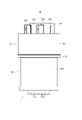
- FIG. 2 is a side view showing the driving device according to the first embodiment
- 3 is a view in the direction of arrow III in FIG. 2
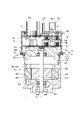
- FIG. 4 is a cross-sectional view taken along line IV-IV of FIG.
- FIG. 5 is a cross-sectional view taken along line VV in FIG.
- FIG. 6 is an exploded perspective view of the driving device according to the first embodiment
- FIG. 7 is an exploded perspective view of the driving device according to the first embodiment
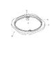
- FIG. 8 is a perspective view of an expansion member according to the first embodiment
- FIG. 9 is a perspective view of an expansion member according to the first embodiment
- FIG. 10 is a plan view of the expansion member according to the first embodiment
- FIG. 11 is a cross-sectional view taken along line XI-AO-XI in FIG.
- FIG. 12 is an enlarged view of the XII section of FIG. 11
- FIG. 13 is an enlarged view of section XIII in FIG. 11,
- 14 is a plan view showing a state in which the expansion member according to the first embodiment is assembled to the motor case
- FIG. FIG. 15 is a sectional view showing the motor and motor frame according to the second embodiment.
- FIGS. 1 to 14 A driving device according to a first embodiment is shown in FIGS. 1 to 14.
- FIG. 1 A driving device according to a first embodiment is shown in FIGS. 1 to 14.
- the driving device 1 includes a motor 80 and an ECU 10, and is applied to an electric power steering device 8 as a steering device for assisting steering operation of a vehicle.
- FIG. 1 shows the overall configuration of a steering system 90 including an electric power steering device 8.
- the steering system 90 includes a steering wheel 91 that is a steering member, a steering shaft 92, a pinion gear 96, a rack shaft 97, wheels 98, an electric power steering device 8, and the like.
- a steering wheel 91 is connected to a steering shaft 92 .
- the steering shaft 92 is provided with a torque sensor 93 that detects steering torque.
- the torque sensor 93 is internally divided into two systems, and the detected values trq1 and trq2 are input to corresponding connectors 153 and 253, respectively.
- a pinion gear 96 is provided at the tip of the steering shaft 92 .
- the pinion gear 96 meshes with the rack shaft 97 .
- a pair of wheels 98 are connected to both ends of the rack shaft 97 via tie rods or the like.
- the electric power steering device 8 includes the driving device 1 and a speed reduction gear 89 as a power transmission unit that reduces the speed of rotation of the motor 80 and transmits it to the rack shaft 97 .
- the electric power steering device 8 of the present embodiment is a so-called "rack assist type", but it may be a so-called “column assist type” that transmits the rotation of the motor 80 to the steering shaft 92, or the like.
- the motor 80 is a three-phase brushless motor.
- the motor 80 outputs part or all of the torque required for steering, and is driven by being supplied with power from a battery (not shown) to rotate the reduction gear 89 forward and backward.
- Motor 80 has a first motor winding 180 and a second motor winding 280 .
- first system a combination of configurations related to energization control of the first motor winding 180
- second system a combination of configurations related to energization control of the second motor winding 280
- the configuration of the first system is mainly numbered in the 100s
- the configuration of the second system L2 is mainly numbered in the 200s. Numbers are assigned so that the digits are the same, and explanations are omitted as appropriate.
- suffix "1" is added to the configuration related to the first system L1
- suffix "2" is added to the configuration related to the second system L2.
- the drive device 1 is integrally provided with the ECU 10 on one side of the motor 80 in the axial direction, and is a so-called "machine-electric integrated type".
- the ECU 10 is arranged coaxially with the axis Ax of the shaft 870 on the side opposite to the output shaft of the motor 80 .
- coaxial means that errors and deviations related to assembly and design are allowed, for example.
- the "mechanical and electrical integration" in the drive device 1 of the present embodiment is different from the motor 80 in which, for example, an approximately rectangular parallelepiped ECU is simply provided close to the motor 80 .
- the ECU 10 and the motor 80 can be efficiently arranged in a vehicle with limited installation space.
- the axial direction of the motor 80 will be regarded as the axial direction of the driving device 1, and will simply be referred to as the "axial direction”.
- the motor 80 has a motor case 830, a motor frame 840, a stator 860, a rotor 865, and the like.
- the stator 860 is fixed to the motor case 830 and has the motor windings 180, 280 wound thereon.
- the rotor 865 is provided radially inside the stator 860 and is provided rotatably relative to the stator 860 .
- the shaft 870 is fitted into the rotor 865 and rotates together with the rotor 865 .
- Shaft 870 is rotatably supported by motor case 830 and motor frame 840 by bearings 871 and 872 .
- An end portion of the shaft 870 on the side of the ECU 10 is inserted through a shaft hole 849 formed in the motor frame 840 and exposed to the side of the ECU 10 .
- a magnet 875 is provided at the end of the shaft 870 on the side of the ECU 10 .
- the motor case 830 is formed in a substantially bottomed tubular shape consisting of a bottom portion 831 and a tubular portion 832, and the ECU 10 is provided on the opening side.
- a bearing 871 is provided on the bottom portion 831 .
- a stator 860 is fixed to the cylindrical portion 832 .
- the motor frame 840 has a frame portion 841, a heat sink 845, a connector connection portion 846, etc., and is made of a material with good thermal conductivity such as aluminum.
- the frame portion 841 is press-fitted radially inward of the motor case 830, and as a whole is within a projected area (hereinafter referred to as “motor silhouette” as appropriate) obtained by projecting the cylindrical portion 832 of the motor case 830 in the axial direction. It's settled.
- a flange portion 842 is formed on the outer circumference of the frame portion 841 and contacts a stepped portion 833 formed on the inner wall of the cylindrical portion 832 .
- An extension member connection portion 843 is formed outside the heat sink 845 of the frame portion 841 .
- the heat sink 845 is erected on the ECU 10 side of the frame portion 841 .
- the heat sink 845 is formed in a substantially rectangular shape in plan view within the motor silhouette.
- Motor wire extraction holes are formed on both sides of the frame portion 841 sandwiching the heat sink 845 .
- An insulating member is provided in the motor wire extraction hole, and recesses are formed in the side surfaces of the heat sink 845 at locations where the motor windings 180 and 280 are extracted. is taken out to the side of the ECU 10 in a state insulated from .
- Motor windings 180 and 280 are connected to main board 31 .
- the connector connecting portion 846 is erected substantially in the center of the side surface of the heat sink 845 from which the motor windings 180 and 280 are not taken out.
- the height of the connector connection portion 846 is higher than the heat sink 845 .
- the ECU 10 has a main board 31, a sub-board 32, power system connection parts 141, 241, signal system connection parts 146, 246, a connector unit 50, a cover 60, and the like.
- the main board 31 is fixed by screws 319 to the board fixing portion 847 (see FIG. 14) of the heat sink 845 .
- the sub-board 32 is fixed to the connector unit 50 .
- the substrates 31 and 32 are larger than the heat sink 845 when projected in the axial direction, and are formed to extend to the outside of the heat sink 845 .
- the main substrate 31 On the surface of the main substrate 31 on the side of the heat sink 845, switching elements, microcomputers, etc. that constitute the inverter are mounted, and are provided on the heat sink 845 so as to be capable of dissipating heat. Components such as capacitors are mounted on the surface of the main substrate 31 opposite to the motor 80 . Some of the elements mounted on the substrates 31 and 32 are omitted.
- the main substrate 31 is formed with relief recesses 316 for avoiding interference with the connector connecting portion 846 .
- the sub-board 32 is formed with relief recesses 326 for avoiding interference with a fixing portion 516 of the connector unit 50, which will be described later.
- the substrates 31 and 32 are hollowed out to form relief recesses 316 and 326 to directly connect the connector unit 50 to the motor frame 840 .
- the main board 31 and the sub-board 32 are connected by power system connection parts 141 and 241 and signal system connection parts 146 and 246 .
- the first power connection component 141 has power terminals 142 , terminal holding portions 143 and pins 144 .
- the power terminal 142 is held by the terminal holding portion 143 and has one end connected to the main board 31 and the other end connected to the sub board 32 .
- the pins 144 are provided on both sides of the terminal holding portion 143 so as to protrude toward the main board 31 , and are fixed to the main board 31 to position the first power system connecting component 141 .
- the second power connection component 241 has power terminals 242 , terminal holding portions 243 and pins 244 .
- the power connection components 141 and 241 are arranged on both sides of the relief recesses 316 and 326 along the same side in the outer area outside the area where various elements such as switching elements are mounted.
- the power connection components 141 and 241 are arranged line-symmetrically with respect to the center line C of the board.
- the first signal system connection component 146 has a plurality of signal terminals 147 , terminal holding portions 148 and pins 149 .
- the signal terminal 147 is held by the terminal holding portion 148 and has one end connected to the main board 31 and the other end connected to the sub board 32 .
- the pins 149 are provided at both ends of the terminal holding portion 148 so as to protrude toward the main substrate 31 side, and are fixed to the main substrate 31 to position the first signal system connection component 146 .
- the second signal system connection component 246 has a plurality of signal terminals 247 , terminal holding portions 248 and pins 249 .
- Signal terminals 147 and 247 are used for signal transmission with torque sensor 93 and vehicle communication network 99 .
- the number of terminals can be arbitrarily set according to the number of signals and the like.
- the signal system connection components 146 and 246 are arranged along the side opposite to the power system connection components 141 and 241 in the outer area outside the area where various elements are mounted, with relief recesses 316 and 326 interposed therebetween. are placed on both sides.
- the signal system connection parts 146 and 246 are arranged line-symmetrically with respect to the center line C of the board.
- the connector unit 50 has a base portion 51, vehicle system connectors 152, 252, and steering system connectors 153, 253.
- the base portion 51 is formed in a substantially rectangular shape in plan view.
- a groove portion 511 is formed along the outer edge of the surface of the base portion 51 opposite to the motor 80 .
- a fixing portion 516 is formed on the base portion 51 .
- a through bolt 519 is inserted through the fixing portion 516 and screwed to the connector connection portion 846 of the motor frame 840 .
- the connector unit 50 is thereby fixed to the motor frame 840 .
- the connection position in the axial direction between the connector connecting portion 846 of the motor frame 840 and the fixing portion 516 of the connector unit 50 is between the main board 31 and the sub-board 32 .
- the connectors 152, 153, 252, and 253 are formed with their frontage facing outward in the axial direction.
- the vehicle system connectors 152 and 252 are integrated with a power connector connected to a vehicle power source and ground (not shown) and a communication connector connected to a vehicle communication network 99 (see FIG. 1) such as a CAN (Controller Area Network). It is an all-in-one hybrid connector.
- the steering system connectors 153 and 253 are connected to the torque sensor 93 .
- the vehicle communication network 99 is indicated as "CAN".
- the cover 60 is formed in a substantially cylindrical shape with a bottom, and accommodates the substrates 31 and 32, the heat sink 845 and the like inside.
- a substantially rectangular hole 61 is formed in the bottom of the cover 60 .
- Connectors 152 , 153 , 252 and 253 are inserted through the holes 61 .
- the end portion 611 of the hole portion 61 is bent inward.
- the end portion 611 is inserted into the groove portion 511 of the connector unit 50 coated with an adhesive member such as an adhesive. This prevents water droplets and dust from entering between the connector unit 50 and the cover 60 .
- the extension member 70 having four corners protruding from the motor silhouette is provided so that the area outside the motor silhouette can be used.
- the extension member 70 has a base portion 71, an annular convex portion 72, a cover insertion groove 73, a fixing portion 74, etc., and is integrally formed of resin or the like.
- the extension member 70 is formed in an annular shape as a whole, and is arranged on the ECU 10 side of the frame portion 841 of the motor frame 840 and radially outside the heat sink 845 .
- the heat sink 845 is formed on the inner peripheral side of the extension member 70 so as to protrude toward the ECU 10 side. At least part of the outer edge of the extension member 70 is located outside the motor silhouette.
- the annular convex portion 72 is provided on the motor 80 side surface of the base portion 71 so as to protrude along the inner peripheral surface, and is inserted into the tubular portion 832 of the motor case 830 .
- an adhesive member such as an adhesive
- water droplets and dust from between the motor case 830 and the extension member 70 can be removed. etc. can be prevented.
- a cover insertion groove 73 is formed along the outer edge of the surface of the expansion member 70 opposite to the motor 80 .
- a flange portion 66 is formed on the cylindrical portion 65 of the cover 60, and the distal end side of the flange portion 66 is inserted into a cover insertion groove 73 coated with an adhesive member such as an adhesive.
- the fixing portion 74 is formed to protrude radially inward from the inner peripheral wall of the expansion member 70 .
- a collar 78 is inserted into the fixed portion 74 and fixed to the frame portion 841 with a screw 79 .
- the extension member 70 is attached to the motor assembly in which the motor frame 840 is attached to the motor case 830 and fixed to the motor frame 840 with the screws 79 .
- the main board 31 with the connecting parts 141 , 146 , 241 , 246 assembled is fixed to the motor frame 840 with screws 319 .
- a heat dissipating gel is appropriately applied to a portion where heat is to be dissipated by the heat sink 845 .
- the connector unit 50 to which the sub-board 32 is assembled is fixed to the motor frame 840 with the through bolts 519, and finally the cover 60 is put on.
- the driving device 1 includes the motor 80, the motor frame 840, the ECU 10, the extension member 70, and the cover 60.
- the motor 80 includes a motor case 830 having a tubular portion 832 , a stator 860 fixed to the motor case 830 , motor windings 180 and 280 wound around the stator 860 , and a rotor 865 provided rotatably relative to the stator 860 . , and a shaft 870 that rotates integrally with the rotor 865 .
- the motor frame 840 is provided on one side of the cylindrical portion 832 in the axial direction.
- the ECU 10 has at least one board 31, 32 on which electronic components related to energization control of the motor windings 180, 280 are mounted, and a connector unit 50, and is arranged on one side of the motor 80 in the axial direction.
- the connector unit 50 has at least one connector 152 , 153 , 252 , 253 erected from the base portion 51 with a frontage facing outward in the axial direction of the motor 80 .
- the extension member 70 is fixed to the motor case 830.
- the cover 60 has holes 61 through which the connectors 152 , 153 , 252 , 253 are inserted, and is fixed to the extension member 70 .
- the substrates 31 and 32 and the extension member 70 are formed to extend to the outside of the projected area where the cylindrical portion 832 of the motor case 830 is projected in the axial direction.
- the ECU 10 can be expanded to the outside of the motor silhouette as compared with the case where the expansion member 70 is not provided.
- a large frontage area of 252 and 253 can be secured.
- the degree of freedom in designing the board and connector can be increased.
- the driving device 1 is applied to the electric power steering device 8.
- the connectors include a power connector connected to a power supply, a communication connector connected to a vehicle communication network 99, and steering system connectors 153 and 253 for acquiring a signal from a torque sensor 93, which is an internal sensor of the electric power steering device 8. It is included.
- the power connector and the communication connector are the vehicle system connectors 152 and 252 that are integrated, but the power connector and the communication connector may be separated.
- a plurality of motor windings 180, 280 are provided. , are provided for each system. Moreover, the steering system connectors 153 and 253 are provided independently of the vehicle system connectors 152 and 252 .
- the frontage area can be secured by providing the expansion member 70, so that the steering system connectors 153 and 253 used for connection inside the electric power steering device 8 and the outside of the electric power steering device 8 are connected.
- the vehicle system connectors 152 and 252 used for connection with the system can be separately provided for each system.
- the boards include a main board 31 fixed to the motor frame 840 and a sub-board 32 fixed to the connector unit 50 .
- the main board 31 and the sub-board 32 are composed of power connection parts 141, 241 having power terminals 142, 242, which are power terminals and ground terminals, and signal connection parts 146, 246 having a plurality of signal terminals 147, 247. are connected outside the element mounting area.
- power connection parts 141, 241 having power terminals 142, 242, which are power terminals and ground terminals
- signal connection parts 146, 246 having a plurality of signal terminals 147, 247. are connected outside the element mounting area.
- a large mounting area can be secured.
- the substrates 31, 32 are mounted.
- a large area for mounting 32 elements can be secured.
- the motor frame 840 is provided with a connector connecting portion 846 erected on the side of the ECU 10 inside the extension member 70 .
- the connector unit 50 is provided with a fixing portion 516 extending toward the motor 80 side.
- the main substrate 31 is formed with an escape recess 316 in which the connector connecting portion 846 is arranged.
- the sub-board 32 is formed with relief recesses 326 in which the fixing portions 516 are arranged.
- the motor frame 840 and the connector unit 50 are fixed at an intermediate position between the main board 31 and the sub-board 32 in the axial direction. As a result, the connector unit 50 can be appropriately fixed to the motor frame 840 while securing a large mounting area for the substrates 31 and 32 .
- the motor frame 840 has a frame portion 841 arranged radially inward of the cylindrical portion 832, and a heat sink 845 erected from the frame portion 841 toward the ECU 10 side and to which the main board 31 is fixed.
- the expansion member 70 is formed in an annular shape, is arranged outside the heat sink 845 , and is fixed to the frame portion 841 . Thereby, the extension member 70 is properly fixed to the motor frame 840 . At least part of the heat of the electronic components mounted on the main substrate 31 can be dissipated to the heat sink 845 side.
- the electric power steering device 8 is a "steering device”
- the ECU 10 is a "control unit”
- the main board 31 and the sub-board 32 are a “board”
- the vehicle system connectors 152 and 252 are a "power connector” and a “communication connector”.
- the steering system connectors 153 and 253 correspond to the "connector”
- the torque sensor 93 corresponds to the "internal sensor”
- the relief recess 316 corresponds to the "main relief recess”
- the relief recess 326 corresponds to the "sub relief recess”.
- the terms "main” and “sub” are used for the sake of convenience, but the relationship between the two substrates does not necessarily have to be main and sub in terms of function.
- FIG. 9 A second embodiment is shown in FIG.
- the motor case 930 is mainly different from the above embodiment, so this point will be mainly described.
- the motor case 930 is formed in a substantially bottomed tubular shape including a bottom portion 931 and a tubular portion 932, and the ECU 10 (not shown in FIG. 15) is provided on the opening side.
- a bearing 871 is provided on the bottom portion 931 .
- a stator 860 is fixed to the cylindrical portion 932 .
- an extension portion 935 as an extension member is integrally provided on the opening side of the tubular portion 932 . Even with this configuration, the same effects as those of the above-described embodiment can be obtained.
- the power connector connected to the vehicle power supply and ground and the communication connector connected to the vehicle communication network are integrated.
- the power connector and communication connector may be separate.
- the type and number of connectors can be set arbitrarily, and the frontages may be provided separately, or may be provided in an arbitrary combination.
- the connector frontage is provided separately for each system.
- one frontage may be shared by a plurality of systems without dividing the connector frontage by system.
- the torque sensor corresponds to the internal sensor.
- the sensor is not limited to the torque sensor, and may be, for example, a steering sensor, as long as the sensor is outside the ECU and inside the steering system.
- two sets of motor windings are provided and the number of systems is two. In other embodiments, the number of strains may be 1 or 3 or more.
- a connector is provided for each system. In other embodiments, the system and connector may not correspond.
- the number of substrates may be one or three or more, and at least one substrate should be formed to extend outside the motor silhouette.
- the steering device is an electric power steering device.
- the steering device may be a steer-by-wire device
- the drive device may be used as a steering device for steering the wheels or as a reaction force device for applying a reaction force to the steering wheel.
- the driving device may be applied to devices other than the steering device.
- the present disclosure is by no means limited to the above embodiments, and can be implemented in various forms without departing from the scope of the present disclosure.
Abstract
A motor case (830, 930) of a motor (80) has a cylindrical part 832. A motor frame (840) is provided to one side in the axial direction of the cylindrical part (832). A control unit (10) has at least one substrate (31, 32) and a connector unit (50), and is disposed on one side in the axial direction of the motor (80). In the connector unit (50), at least one connector (152, 153, 252, 253) having a front opening which faces outward in the axial direction of the motor (80) is provided rising from a base part (51). An extension member (70, 935) is fixed to the motor case (830). A cover (60) has a hole (61) into which the connector (152, 153, 252, 253) is inserted, and is fixed to the extension member (70). The extension member (70) is formed extending to outside a projection region resulting from projecting the cylindrical part (832) of the motor case (830) in the axial direction.
Description
本出願は、2021年3月18日に出願された特許出願番号2021-045039号に基づくものであり、ここにその記載内容を援用する。
This application is based on Patent Application No. 2021-045039 filed on March 18, 2021, and the contents thereof are incorporated herein.
本開示は、駆動装置に関する。
The present disclosure relates to a driving device.
従来、モータと制御ユニット部とが一体となった駆動装置が知られている。例えば特許文献1では、コネクタと一体に形成されたハウジングは、フレームの軸方向の端面にネジ等により固定されている。
Conventionally, a driving device in which a motor and a control unit are integrated is known. For example, in Patent Document 1, a housing integrally formed with a connector is fixed to an axial end face of a frame by means of screws or the like.
しかしながら、特許文献1のように、コネクタ一体型のハウジングを、モータケースの径方向内側に嵌め込まれているフレームに固定する場合、コネクタ間口や、フレームとハウジングとの間に形成される空間に配置される基板等をモータ径サイズ内に収める必要がある。本開示の目的は、設計自由度を向上可能な駆動装置を提供することにある。
However, when a connector-integrated housing is fixed to a frame that is fitted radially inward of a motor case as in Patent Document 1, it is arranged in the connector opening or in the space formed between the frame and the housing. It is necessary to fit the substrate, etc., within the diameter size of the motor. An object of the present disclosure is to provide a driving device capable of improving the degree of design freedom.
本開示の駆動装置は、モータと、モータフレームと、制御ユニットと、拡張部材と、カバーと、を備える。モータは、筒部を有するモータケース、モータケースに固定されるステータ、ステータに巻回されるモータ巻線、ステータに対して相対回転可能に設けられるロータ、および、ロータと一体に回転するシャフトを有する。モータフレームは、筒部の軸方向の一方側に設けられる。
A drive device of the present disclosure includes a motor, a motor frame, a control unit, an extension member, and a cover. A motor includes a motor case having a tubular portion, a stator fixed to the motor case, motor windings wound around the stator, a rotor provided to be rotatable relative to the stator, and a shaft rotating integrally with the rotor. have. The motor frame is provided on one side of the cylindrical portion in the axial direction.
制御ユニットは、少なくとも1つの基板、および、コネクタユニットを有し、モータの軸方向の一方側に配置される。基板には、モータ巻線への通電制御に係る電子部品が実装される。コネクタユニットは、間口がモータの軸方向外側を向く少なくとも1つのコネクタがベース部から立設している。拡張部材は、モータケースに固定される。カバーは、コネクタが挿通される孔部を有し、拡張部材に固定される。拡張部材は、モータケースの筒部を軸方向に投影した投影領域の外側まで延びて形成されている。
The control unit has at least one board and a connector unit, and is arranged on one side of the motor in the axial direction. On the board, electronic components related to control of energization to the motor windings are mounted. The connector unit has at least one connector erected from the base portion with a frontage facing outward in the axial direction of the motor. The extension member is fixed to the motor case. The cover has a hole through which the connector is inserted and is fixed to the expansion member. The expansion member is formed to extend to the outside of the projection area in which the cylindrical portion of the motor case is projected in the axial direction.
これにより、モータケースの筒部の投影領域の外側まで制御ユニットを拡張可能であるので、基板の実装面積やコネクタユニットの間口面積を大きく確保することができ、設計自由度を高めることができる。
As a result, the control unit can be extended to the outside of the projection area of the cylindrical portion of the motor case, so a large board mounting area and connector unit frontage area can be secured, and the degree of freedom in design can be increased.
本開示についての上記目的及びその他の目的、特徴や利点は、添付の図面を参照しながら下記の詳細な記述により、より明確になる。その図面は、
図1は、第1実施形態によるステアリングシステムを示す概略構成図であり、
図2は、第1実施形態による駆動装置を示す側面図であり、
図3は、図2のIII方向矢視図であり、
図4は、図3のIV-IV線断面図であり、
図5は、図3のV-V線断面図であり、
図6は、第1実施形態による駆動装置の分解斜視図であり、
図7は、第1実施形態による駆動装置の分解斜視図であり、
図8は、第1実施形態による拡張部材の斜視図であり、
図9は、第1実施形態による拡張部材の斜視図であり、
図10は、第1実施形態による拡張部材の平面図であり、
図11は、図10のXI-A-O-XI線断面図であり、
図12は、図11のXII部を拡大した拡大図であり、
図13は、図11のXIII部を拡大した拡大図であり、
図14は、第1実施形態による拡張部材をモータケースに組み付けた状態を示す平面図であり、
図15は、第2実施形態によるモータおよびモータフレームを示す断面図である。
The above and other objects, features and advantages of the present disclosure will become more apparent from the following detailed description with reference to the accompanying drawings. The drawing is
FIG. 1 is a schematic configuration diagram showing a steering system according to the first embodiment, FIG. 2 is a side view showing the driving device according to the first embodiment; 3 is a view in the direction of arrow III in FIG. 2, FIG. 4 is a cross-sectional view taken along line IV-IV of FIG. FIG. 5 is a cross-sectional view taken along line VV in FIG. FIG. 6 is an exploded perspective view of the driving device according to the first embodiment; FIG. 7 is an exploded perspective view of the driving device according to the first embodiment; FIG. 8 is a perspective view of an expansion member according to the first embodiment; FIG. 9 is a perspective view of an expansion member according to the first embodiment; FIG. 10 is a plan view of the expansion member according to the first embodiment; FIG. 11 is a cross-sectional view taken along line XI-AO-XI in FIG. FIG. 12 is an enlarged view of the XII section of FIG. 11, FIG. 13 is an enlarged view of section XIII in FIG. 11, 14 is a plan view showing a state in which the expansion member according to the first embodiment is assembled to the motor case; FIG. FIG. 15 is a sectional view showing the motor and motor frame according to the second embodiment.
(第1実施形態)
以下、駆動装置を図面に基づいて説明する。以下、複数の実施形態において、実質的に同一の構成には同一の符号を付して説明を省略する。第1実施形態による駆動装置を図1~図14に示す。 (First embodiment)
The driving device will be described below with reference to the drawings. Hereinafter, in a plurality of embodiments, substantially the same configurations are denoted by the same reference numerals, and descriptions thereof are omitted. A driving device according to a first embodiment is shown in FIGS. 1 to 14. FIG.
図1に示すように、駆動装置1は、モータ80と、ECU10と、を備え、車両のステアリング操作を補助するための操舵装置としての電動パワーステアリング装置8に適用される。図1は、電動パワーステアリング装置8を備えるステアリングシステム90の全体構成を示すものである。ステアリングシステム90は、操舵部材であるステアリングホイール91、ステアリングシャフト92、ピニオンギア96、ラック軸97、車輪98、および、電動パワーステアリング装置8等を備える。
As shown in FIG. 1, the driving device 1 includes a motor 80 and an ECU 10, and is applied to an electric power steering device 8 as a steering device for assisting steering operation of a vehicle. FIG. 1 shows the overall configuration of a steering system 90 including an electric power steering device 8. As shown in FIG. The steering system 90 includes a steering wheel 91 that is a steering member, a steering shaft 92, a pinion gear 96, a rack shaft 97, wheels 98, an electric power steering device 8, and the like.
ステアリングホイール91は、ステアリングシャフト92と接続される。ステアリングシャフト92には、操舵トルクを検出するトルクセンサ93が設けられる。トルクセンサ93は、内部にて2系統化されており、それぞれの検出値trq1、trq2は、対応するコネクタ153、253に入力される。ステアリングシャフト92の先端には、ピニオンギア96が設けられる。ピニオンギア96は、ラック軸97に噛み合っている。ラック軸97の両端には、タイロッド等を介して一対の車輪98が連結される。
A steering wheel 91 is connected to a steering shaft 92 . The steering shaft 92 is provided with a torque sensor 93 that detects steering torque. The torque sensor 93 is internally divided into two systems, and the detected values trq1 and trq2 are input to corresponding connectors 153 and 253, respectively. A pinion gear 96 is provided at the tip of the steering shaft 92 . The pinion gear 96 meshes with the rack shaft 97 . A pair of wheels 98 are connected to both ends of the rack shaft 97 via tie rods or the like.
運転者がステアリングホイール91を回転させると、ステアリングホイール91に接続されたステアリングシャフト92が回転する。ステアリングシャフト92の回転運動は、ピニオンギア96によってラック軸97の直線運動に変換される。一対の車輪98は、ラック軸97の変位量に応じた角度に操舵される。
When the driver rotates the steering wheel 91, the steering shaft 92 connected to the steering wheel 91 rotates. Rotational motion of the steering shaft 92 is converted into linear motion of the rack shaft 97 by the pinion gear 96 . A pair of wheels 98 are steered to an angle corresponding to the amount of displacement of the rack shaft 97 .
電動パワーステアリング装置8は、駆動装置1、および、モータ80の回転を減速してラック軸97に伝える動力伝達部としての減速ギア89等を備える。本実施形態の電動パワーステアリング装置8は、所謂「ラックアシストタイプ」であるが、モータ80の回転をステアリングシャフト92に伝える所謂「コラムアシストタイプ」等としてもよい。
The electric power steering device 8 includes the driving device 1 and a speed reduction gear 89 as a power transmission unit that reduces the speed of rotation of the motor 80 and transmits it to the rack shaft 97 . The electric power steering device 8 of the present embodiment is a so-called "rack assist type", but it may be a so-called "column assist type" that transmits the rotation of the motor 80 to the steering shaft 92, or the like.
図2~図7に示すように、モータ80は3相ブラシレスモータである。モータ80は、操舵に要するトルクの一部または全部を出力するものであって、図示しないバッテリから電力が供給されることで駆動され、減速ギア89を正逆回転させる。モータ80は、第1モータ巻線180および第2モータ巻線280を有する。
As shown in FIGS. 2 to 7, the motor 80 is a three-phase brushless motor. The motor 80 outputs part or all of the torque required for steering, and is driven by being supplied with power from a battery (not shown) to rotate the reduction gear 89 forward and backward. Motor 80 has a first motor winding 180 and a second motor winding 280 .
以下、第1モータ巻線180の通電制御に係る構成の組み合わせを第1系統、第2モータ巻線280の通電制御に係る構成の組み合わせを第2系統とする。第1系統の構成を主に100番台で付番し、第2系統L2の構成を主に200番台で付番し、第1系統と第2系統とで実質的に同様の構成には下2桁が同じとなるように付番し、適宜説明を省略する。また適宜、第1系統L1に係る構成に添え字の「1」、第2系統L2に係る構成に添え字の「2」を付す。
Hereinafter, a combination of configurations related to energization control of the first motor winding 180 will be referred to as a first system, and a combination of configurations related to energization control of the second motor winding 280 will be referred to as a second system. The configuration of the first system is mainly numbered in the 100s, and the configuration of the second system L2 is mainly numbered in the 200s. Numbers are assigned so that the digits are the same, and explanations are omitted as appropriate. In addition, the suffix "1" is added to the configuration related to the first system L1, and the suffix "2" is added to the configuration related to the second system L2.
駆動装置1は、モータ80の軸方向の一方側にECU10が一体的に設けられており、いわゆる「機電一体型」である。ECU10は、モータ80の出力軸とは反対側において、シャフト870の軸Axに対して同軸に配置されている。ここで、「同軸」とは、例えば組み付けや設計に係る誤差やズレは許容されるものとする。
The drive device 1 is integrally provided with the ECU 10 on one side of the motor 80 in the axial direction, and is a so-called "machine-electric integrated type". The ECU 10 is arranged coaxially with the axis Ax of the shaft 870 on the side opposite to the output shaft of the motor 80 . Here, "coaxial" means that errors and deviations related to assembly and design are allowed, for example.
なお、本実施形態の駆動装置1における「機電一体」とは、モータ80に対し、例えば概ね直方体形状のECUを単に近接させて設けたものとは異なっている。機電一体型とすることで、搭載スペースに制約のある車両において、ECU10とモータ80とを効率的に配置することができる。以下、モータ80の軸方向を駆動装置1の軸方向とみなし、単に「軸方向」とする。
It should be noted that the "mechanical and electrical integration" in the drive device 1 of the present embodiment is different from the motor 80 in which, for example, an approximately rectangular parallelepiped ECU is simply provided close to the motor 80 . By adopting the integrated electromechanical type, the ECU 10 and the motor 80 can be efficiently arranged in a vehicle with limited installation space. Hereinafter, the axial direction of the motor 80 will be regarded as the axial direction of the driving device 1, and will simply be referred to as the "axial direction".
モータ80は、モータケース830、モータフレーム840、ステータ860、および、ロータ865等を有する。ステータ860は、モータケース830に固定されており、モータ巻線180、280が巻回される。ロータ865は、ステータ860の径方向内側に設けられ、ステータ860に対して相対回転可能に設けられる。
The motor 80 has a motor case 830, a motor frame 840, a stator 860, a rotor 865, and the like. The stator 860 is fixed to the motor case 830 and has the motor windings 180, 280 wound thereon. The rotor 865 is provided radially inside the stator 860 and is provided rotatably relative to the stator 860 .
シャフト870は、ロータ865に嵌入され、ロータ865と一体に回転する。シャフト870は、軸受871、872により、モータケース830およびモータフレーム840に回転可能に支持される。シャフト870のECU10側の端部は、モータフレーム840に形成される軸孔849に挿通され、ECU10側に露出する。シャフト870のECU10側の端部には、マグネット875が設けられる。
The shaft 870 is fitted into the rotor 865 and rotates together with the rotor 865 . Shaft 870 is rotatably supported by motor case 830 and motor frame 840 by bearings 871 and 872 . An end portion of the shaft 870 on the side of the ECU 10 is inserted through a shaft hole 849 formed in the motor frame 840 and exposed to the side of the ECU 10 . A magnet 875 is provided at the end of the shaft 870 on the side of the ECU 10 .
モータケース830は、底部831および筒部832からなる略有底筒状に形成され、開口側にECU10が設けられる。底部831には、軸受871が設けられる。筒部832には、ステータ860が固定される。
The motor case 830 is formed in a substantially bottomed tubular shape consisting of a bottom portion 831 and a tubular portion 832, and the ECU 10 is provided on the opening side. A bearing 871 is provided on the bottom portion 831 . A stator 860 is fixed to the cylindrical portion 832 .
モータフレーム840は、フレーム部841、ヒートシンク845、および、コネクタ接続部846等を有し、例えばアルミ等の熱伝導性のよい材料で形成される。フレーム部841は、モータケース830の径方向内側に圧入されており、全体として、モータケース830の筒部832を軸方向に投影した投影領域(以下適宜、「モータシルエット」とする。)内に収まっている。フレーム部841の外周には、フランジ部842が形成され、筒部832の内壁に形成される段差部833と当接する。また、フレーム部841のヒートシンク845の外側には、拡張部材接続部843が形成される。
The motor frame 840 has a frame portion 841, a heat sink 845, a connector connection portion 846, etc., and is made of a material with good thermal conductivity such as aluminum. The frame portion 841 is press-fitted radially inward of the motor case 830, and as a whole is within a projected area (hereinafter referred to as “motor silhouette” as appropriate) obtained by projecting the cylindrical portion 832 of the motor case 830 in the axial direction. It's settled. A flange portion 842 is formed on the outer circumference of the frame portion 841 and contacts a stepped portion 833 formed on the inner wall of the cylindrical portion 832 . An extension member connection portion 843 is formed outside the heat sink 845 of the frame portion 841 .
ヒートシンク845は、フレーム部841のECU10側に立設される。ヒートシンク845は、モータシルエット内にて、平面視略矩形に形成されている。フレーム部841のヒートシンク845を挟んだ両側には、モータ線取出孔が形成されている。モータ線取出孔には絶縁部材が設けられ、モータ巻線180、280が取り出される箇所にてヒートシンク845の側面には凹部が形成されており、モータ巻線180、280の一端は、モータフレーム840と絶縁した状態にてECU10側に取り出される。モータ巻線180、280は、メイン基板31と接続される。
The heat sink 845 is erected on the ECU 10 side of the frame portion 841 . The heat sink 845 is formed in a substantially rectangular shape in plan view within the motor silhouette. Motor wire extraction holes are formed on both sides of the frame portion 841 sandwiching the heat sink 845 . An insulating member is provided in the motor wire extraction hole, and recesses are formed in the side surfaces of the heat sink 845 at locations where the motor windings 180 and 280 are extracted. is taken out to the side of the ECU 10 in a state insulated from . Motor windings 180 and 280 are connected to main board 31 .
コネクタ接続部846は、モータ巻線180、280が取り出されない側のヒートシンク845の側面の略中央に立設されている。コネクタ接続部846の高さは、ヒートシンク845よりも高い。
The connector connecting portion 846 is erected substantially in the center of the side surface of the heat sink 845 from which the motor windings 180 and 280 are not taken out. The height of the connector connection portion 846 is higher than the heat sink 845 .
ECU10は、メイン基板31、サブ基板32、パワー系接続部品141、241、信号系接続部品146、246、コネクタユニット50、および、カバー60等を有する。メイン基板31は、ヒートシンク845の基板固定部847(図14参照)にねじ319にて固定される。サブ基板32は、コネクタユニット50に固定される。基板31、32は、軸方向に投影したとき、ヒートシンク845より大きく、ヒートシンク845の外側まで延びて形成されている。
The ECU 10 has a main board 31, a sub-board 32, power system connection parts 141, 241, signal system connection parts 146, 246, a connector unit 50, a cover 60, and the like. The main board 31 is fixed by screws 319 to the board fixing portion 847 (see FIG. 14) of the heat sink 845 . The sub-board 32 is fixed to the connector unit 50 . The substrates 31 and 32 are larger than the heat sink 845 when projected in the axial direction, and are formed to extend to the outside of the heat sink 845 .
メイン基板31のヒートシンク845側の面には、インバータを構成するスイッチング素子やマイコン等が実装され、ヒートシンク845に放熱可能に設けられている。メイン基板31のモータ80と反対側の面には、コンデンサ等の部品が実装される。なお、基板31、32に実装されている素子の一部は記載を省略した。メイン基板31には、コネクタ接続部846との干渉を避けるための逃がし凹部316が形成されている。
On the surface of the main substrate 31 on the side of the heat sink 845, switching elements, microcomputers, etc. that constitute the inverter are mounted, and are provided on the heat sink 845 so as to be capable of dissipating heat. Components such as capacitors are mounted on the surface of the main substrate 31 opposite to the motor 80 . Some of the elements mounted on the substrates 31 and 32 are omitted. The main substrate 31 is formed with relief recesses 316 for avoiding interference with the connector connecting portion 846 .
サブ基板32には、フィルタ回路を構成するチョークコイルおよびコンデンサ等の部品が実装される。サブ基板32には、後述するコネクタユニット50の固定部516との干渉を避けるための逃がし凹部326が形成されている。本実施形態では、基板31、32をえぐり、逃がし凹部316、326を形成し、コネクタユニット50をモータフレーム840に直接締結している。
Components such as choke coils and capacitors that make up the filter circuit are mounted on the sub-board 32 . The sub-board 32 is formed with relief recesses 326 for avoiding interference with a fixing portion 516 of the connector unit 50, which will be described later. In this embodiment, the substrates 31 and 32 are hollowed out to form relief recesses 316 and 326 to directly connect the connector unit 50 to the motor frame 840 .
メイン基板31とサブ基板32とは、パワー系接続部品141、241、および、信号系接続部品146、246で接続される。第1パワー系接続部品141は、パワー端子142、端子保持部143、および、ピン144を有する。パワー端子142は2つであって、一方が電源端子、他方がグランド端子である。パワー端子142は、端子保持部143に保持され、一端がメイン基板31と接続され、他端がサブ基板32と接続される。ピン144は、端子保持部143の両側において、メイン基板31側に突出して設けられ、メイン基板31に固定されることで第1パワー系接続部品141を位置決めする。第2パワー系接続部品241は、パワー端子242、端子保持部243、および、ピン244を有する。
The main board 31 and the sub-board 32 are connected by power system connection parts 141 and 241 and signal system connection parts 146 and 246 . The first power connection component 141 has power terminals 142 , terminal holding portions 143 and pins 144 . There are two power terminals 142, one of which is a power terminal and the other is a ground terminal. The power terminal 142 is held by the terminal holding portion 143 and has one end connected to the main board 31 and the other end connected to the sub board 32 . The pins 144 are provided on both sides of the terminal holding portion 143 so as to protrude toward the main board 31 , and are fixed to the main board 31 to position the first power system connecting component 141 . The second power connection component 241 has power terminals 242 , terminal holding portions 243 and pins 244 .
パワー系接続部品141、241は、スイッチング素子等の各種素子が実装される領域の外側である外側領域において、同一辺に沿い、逃がし凹部316、326を挟んで両側に配置されている。パワー系接続部品141、241は、基板中心線Cに対して線対称に配置されている。
The power connection components 141 and 241 are arranged on both sides of the relief recesses 316 and 326 along the same side in the outer area outside the area where various elements such as switching elements are mounted. The power connection components 141 and 241 are arranged line-symmetrically with respect to the center line C of the board.
第1信号系接続部品146は、複数の信号端子147、端子保持部148、および、ピン149を有する。信号端子147は、端子保持部148に保持され、一端がメイン基板31と接続され、他端がサブ基板32と接続される。ピン149は、端子保持部148の両端において、メイン基板31側に突出して設けられ、メイン基板31に固定されることで第1信号系接続部品146を位置決めする。第2信号系接続部品246は、複数の信号端子247、端子保持部248、および、ピン249を有する。信号端子147、247は、トルクセンサ93および車両通信網99との信号伝達に用いられる。端子数は、信号数等に応じ、任意に設定可能である。
The first signal system connection component 146 has a plurality of signal terminals 147 , terminal holding portions 148 and pins 149 . The signal terminal 147 is held by the terminal holding portion 148 and has one end connected to the main board 31 and the other end connected to the sub board 32 . The pins 149 are provided at both ends of the terminal holding portion 148 so as to protrude toward the main substrate 31 side, and are fixed to the main substrate 31 to position the first signal system connection component 146 . The second signal system connection component 246 has a plurality of signal terminals 247 , terminal holding portions 248 and pins 249 . Signal terminals 147 and 247 are used for signal transmission with torque sensor 93 and vehicle communication network 99 . The number of terminals can be arbitrarily set according to the number of signals and the like.
信号系接続部品146、246は、各種素子が実装される領域の外側である外側領域において、パワー系接続部品141、241が設けられるのと反対側の辺に沿い、逃がし凹部316、326を挟んで両側に配置されている。信号系接続部品146、246は、基板中心線Cに対して線対称に配置されている。
The signal system connection components 146 and 246 are arranged along the side opposite to the power system connection components 141 and 241 in the outer area outside the area where various elements are mounted, with relief recesses 316 and 326 interposed therebetween. are placed on both sides. The signal system connection parts 146 and 246 are arranged line-symmetrically with respect to the center line C of the board.
コネクタユニット50は、ベース部51、車両系コネクタ152、252、および、操舵系コネクタ153、253を有する。ベース部51は、平面視略矩形に形成される。ベース部51のモータ80と反対側の面には、外縁に沿って溝部511が形成されている。また、ベース部51には、固定部516が形成される。固定部516には、スルーボルト519が挿通され、モータフレーム840のコネクタ接続部846に螺着される。これにより、コネクタユニット50がモータフレーム840に固定される。モータフレーム840のコネクタ接続部846とコネクタユニット50の固定部516との軸方向における接続位置は、メイン基板31とサブ基板32との間である。
The connector unit 50 has a base portion 51, vehicle system connectors 152, 252, and steering system connectors 153, 253. The base portion 51 is formed in a substantially rectangular shape in plan view. A groove portion 511 is formed along the outer edge of the surface of the base portion 51 opposite to the motor 80 . A fixing portion 516 is formed on the base portion 51 . A through bolt 519 is inserted through the fixing portion 516 and screwed to the connector connection portion 846 of the motor frame 840 . The connector unit 50 is thereby fixed to the motor frame 840 . The connection position in the axial direction between the connector connecting portion 846 of the motor frame 840 and the fixing portion 516 of the connector unit 50 is between the main board 31 and the sub-board 32 .
コネクタ152、153、252、253は、間口が軸方向外側を向いて形成されている。車両系コネクタ152、252は、図示しない車両電源およびグランドと接続されるパワーコネクタと、CAN(Controller Area Network)等である車両通信網99(図1参照)と接続される通信コネクタとが一体になった一体型のハイブリッドコネクタである。操舵系コネクタ153、253は、トルクセンサ93と接続される。図1では、車両通信網99を「CAN」と記載した。
The connectors 152, 153, 252, and 253 are formed with their frontage facing outward in the axial direction. The vehicle system connectors 152 and 252 are integrated with a power connector connected to a vehicle power source and ground (not shown) and a communication connector connected to a vehicle communication network 99 (see FIG. 1) such as a CAN (Controller Area Network). It is an all-in-one hybrid connector. The steering system connectors 153 and 253 are connected to the torque sensor 93 . In FIG. 1, the vehicle communication network 99 is indicated as "CAN".
カバー60は、略有底筒状に形成され、内部に基板31、32およびヒートシンク845等を収容する。カバー60の底部には、略矩形の孔部61が形成される。孔部61には、コネクタ152、153、252、253が挿通される。孔部61は端部611が内側に折り曲げられている。端部611は、接着材等である接着部材が塗布されたコネクタユニット50の溝部511に挿入される。これにより、コネクタユニット50とカバー60との間からの水滴や埃の侵入を防ぐことができる。
The cover 60 is formed in a substantially cylindrical shape with a bottom, and accommodates the substrates 31 and 32, the heat sink 845 and the like inside. A substantially rectangular hole 61 is formed in the bottom of the cover 60 . Connectors 152 , 153 , 252 and 253 are inserted through the holes 61 . The end portion 611 of the hole portion 61 is bent inward. The end portion 611 is inserted into the groove portion 511 of the connector unit 50 coated with an adhesive member such as an adhesive. This prevents water droplets and dust from entering between the connector unit 50 and the cover 60 .
本実施形態では、車両系コネクタ152、252および操舵系コネクタ153、253の4つの間口を設けており、間口面積が大きい。そこで本実施形態では、モータシルエットから四隅が張り出す形状の拡張部材70を設けることで、モータシルエットの外側の領域を利用可能にしている。
In this embodiment, four frontages are provided for vehicle system connectors 152, 252 and steering system connectors 153, 253, and the frontage area is large. Therefore, in the present embodiment, the extension member 70 having four corners protruding from the motor silhouette is provided so that the area outside the motor silhouette can be used.
図8~図14に示すように、拡張部材70は、基部71、環状凸部72、カバー挿入溝73、および、固定部74等を有し、樹脂等にて一体に形成される。拡張部材70は、全体として環状に形成され、モータフレーム840のフレーム部841のECU10側であって、ヒートシンク845の径方向外側に配置される。換言すると、ヒートシンク845は、拡張部材70の内周側にて、ECU10側に突出して形成されている。拡張部材70の外縁の少なくとも一部は、モータシルエットよりも外側に位置している。
As shown in FIGS. 8 to 14, the extension member 70 has a base portion 71, an annular convex portion 72, a cover insertion groove 73, a fixing portion 74, etc., and is integrally formed of resin or the like. The extension member 70 is formed in an annular shape as a whole, and is arranged on the ECU 10 side of the frame portion 841 of the motor frame 840 and radially outside the heat sink 845 . In other words, the heat sink 845 is formed on the inner peripheral side of the extension member 70 so as to protrude toward the ECU 10 side. At least part of the outer edge of the extension member 70 is located outside the motor silhouette.
環状凸部72は、基部71のモータ80側の面に内周面に沿うように突出して設けられ、モータケース830の筒部832に挿入される。モータケース830の段差部833に接着材等である接着部材を塗布した状態にて環状凸部72を筒部832に挿入することで、モータケース830と拡張部材70との間からの水滴や埃等の侵入を防ぐことができる。
The annular convex portion 72 is provided on the motor 80 side surface of the base portion 71 so as to protrude along the inner peripheral surface, and is inserted into the tubular portion 832 of the motor case 830 . By inserting the annular convex portion 72 into the cylindrical portion 832 in a state in which an adhesive member such as an adhesive is applied to the stepped portion 833 of the motor case 830 , water droplets and dust from between the motor case 830 and the extension member 70 can be removed. etc. can be prevented.
拡張部材70のモータ80と反対側の面には、カバー挿入溝73が外縁に沿って形成される。カバー60の筒部65には、フランジ部66が形成されており、フランジ部66よりも先端側が、接着材等である接着部材が塗布されたカバー挿入溝73に挿入される。これにより、拡張部材70とカバー60との間からの水滴や埃等の侵入を防ぐことができる。固定部74は、拡張部材70の内周壁から径方向内側に突出して形成される。固定部74には、カラー78が挿入され、ねじ79にてフレーム部841に固定される。
A cover insertion groove 73 is formed along the outer edge of the surface of the expansion member 70 opposite to the motor 80 . A flange portion 66 is formed on the cylindrical portion 65 of the cover 60, and the distal end side of the flange portion 66 is inserted into a cover insertion groove 73 coated with an adhesive member such as an adhesive. As a result, water droplets, dust, etc. can be prevented from entering between the expansion member 70 and the cover 60 . The fixing portion 74 is formed to protrude radially inward from the inner peripheral wall of the expansion member 70 . A collar 78 is inserted into the fixed portion 74 and fixed to the frame portion 841 with a screw 79 .
駆動装置1の組み付けを説明する。まず、モータケース830にモータフレーム840が組み付けられた状態のモータAssyに、拡張部材70を組み付け、ねじ79にてモータフレーム840に固定する。
The assembly of the drive device 1 will be explained. First, the extension member 70 is attached to the motor assembly in which the motor frame 840 is attached to the motor case 830 and fixed to the motor frame 840 with the screws 79 .
次に、接続部品141、146、241、246が組み付けられたメイン基板31を、ねじ319にてモータフレーム840に固定する。このとき、ヒートシンク845に放熱させる箇所には、適宜放熱ゲルを塗布しておく。次に、サブ基板32が組み付けられたコネクタユニット50をスルーボルト519にてモータフレーム840に固定し、最後にカバー60をかぶせる。
Next, the main board 31 with the connecting parts 141 , 146 , 241 , 246 assembled is fixed to the motor frame 840 with screws 319 . At this time, a heat dissipating gel is appropriately applied to a portion where heat is to be dissipated by the heat sink 845 . Next, the connector unit 50 to which the sub-board 32 is assembled is fixed to the motor frame 840 with the through bolts 519, and finally the cover 60 is put on.
以上説明したように、駆動装置1は、モータ80と、モータフレーム840と、ECU10と、拡張部材70と、カバー60と、を備える。モータ80は、筒部832を有するモータケース830、モータケース830に固定されるステータ860、ステータ860に巻回されるモータ巻線180、280、ステータ860に対して相対回転可能に設けられるロータ865、および、ロータ865と一体に回転するシャフト870を有する。モータフレーム840は、筒部832の軸方向の一方側に設けられる。
As described above, the driving device 1 includes the motor 80, the motor frame 840, the ECU 10, the extension member 70, and the cover 60. The motor 80 includes a motor case 830 having a tubular portion 832 , a stator 860 fixed to the motor case 830 , motor windings 180 and 280 wound around the stator 860 , and a rotor 865 provided rotatably relative to the stator 860 . , and a shaft 870 that rotates integrally with the rotor 865 . The motor frame 840 is provided on one side of the cylindrical portion 832 in the axial direction.
ECU10は、モータ巻線180、280の通電制御に係る電子部品が実装される少なくとも1つの基板31、32、および、コネクタユニット50を有し、モータ80の軸方向の一方側に配置される。コネクタユニット50は、間口がモータ80の軸方向外側を向く少なくとも1つのコネクタ152、153、252、253がベース部51から立設している。
The ECU 10 has at least one board 31, 32 on which electronic components related to energization control of the motor windings 180, 280 are mounted, and a connector unit 50, and is arranged on one side of the motor 80 in the axial direction. The connector unit 50 has at least one connector 152 , 153 , 252 , 253 erected from the base portion 51 with a frontage facing outward in the axial direction of the motor 80 .
拡張部材70は、モータケース830に固定されている。カバー60は、コネクタ152、153、252、253が挿通される孔部61を有し、拡張部材70に固定される。基板31、32および拡張部材70は、モータケース830の筒部832を軸方向に投影した投影領域の外側まで延びて形成される。
The extension member 70 is fixed to the motor case 830. The cover 60 has holes 61 through which the connectors 152 , 153 , 252 , 253 are inserted, and is fixed to the extension member 70 . The substrates 31 and 32 and the extension member 70 are formed to extend to the outside of the projected area where the cylindrical portion 832 of the motor case 830 is projected in the axial direction.
本実施形態では、拡張部材70を設けることで、拡張部材70を設けない場合と比較し、ECU10をモータシルエットの外側まで拡張可能であるので、基板31、32の実装面積やコネクタ152、153、252、253の間口面積を大きく確保することができる。これにより、基板やコネクタの設計自由度を高めることができる。
In this embodiment, by providing the expansion member 70, the ECU 10 can be expanded to the outside of the motor silhouette as compared with the case where the expansion member 70 is not provided. A large frontage area of 252 and 253 can be secured. As a result, the degree of freedom in designing the board and connector can be increased.
駆動装置1は、電動パワーステアリング装置8に適用される。コネクタには、電源と接続されるパワーコネクタ、車両通信網99と接続される通信コネクタ、および、電動パワーステアリング装置8の内部センサであるトルクセンサ93からの信号を取得する操舵系コネクタ153、253が含まれている。本実施形態では、パワーコネクタと通信コネクタとは一体化された車両系コネクタ152、252となっているが、パワーコネクタと通信コネクタとを分けてもよい。
The driving device 1 is applied to the electric power steering device 8. The connectors include a power connector connected to a power supply, a communication connector connected to a vehicle communication network 99, and steering system connectors 153 and 253 for acquiring a signal from a torque sensor 93, which is an internal sensor of the electric power steering device 8. It is included. In this embodiment, the power connector and the communication connector are the vehicle system connectors 152 and 252 that are integrated, but the power connector and the communication connector may be separated.
モータ巻線180、280は、複数(本実施形態は2組)であって、モータ巻線180、280に対応する構成を系統とすると、車両系コネクタ152、252および操舵系コネクタ153、253は、それぞれ系統毎に設けられている。また、操舵系コネクタ153、253は、車両系コネクタ152、252とは独立して設けられている。
A plurality of motor windings 180, 280 (two pairs in the present embodiment) are provided. , are provided for each system. Moreover, the steering system connectors 153 and 253 are provided independently of the vehicle system connectors 152 and 252 .
本実施形態では、拡張部材70を設けることで、間口面積を確保可能であるので、電動パワーステアリング装置8の内部での接続に用いられる操舵系コネクタ153、253と、電動パワーステアリング装置8の外部との接続に用いられる車両系コネクタ152、252とを系統毎に分けて設けることができる。
In the present embodiment, the frontage area can be secured by providing the expansion member 70, so that the steering system connectors 153 and 253 used for connection inside the electric power steering device 8 and the outside of the electric power steering device 8 are connected. The vehicle system connectors 152 and 252 used for connection with the system can be separately provided for each system.
基板には、モータフレーム840に固定されるメイン基板31、および、コネクタユニット50に固定されるサブ基板32が含まれる。メイン基板31とサブ基板32とは、電源端子およびグランド端子であるパワー端子142、242を有するパワー系接続部品141、241、および、複数の信号端子147、247を有する信号系接続部品146、246により、素子実装領域の外側で接続される。本実施形態では、2枚の基板31、32を設けることで、実装面積を大きく確保することができる。また、パワー系接続部品141、241および信号系接続部品146、246を用い、各種電子部品が実装されている領域である素子実装領域の外側で基板31、32を接続することで、基板31、32の素子実装領域を大きく確保することができる。
The boards include a main board 31 fixed to the motor frame 840 and a sub-board 32 fixed to the connector unit 50 . The main board 31 and the sub-board 32 are composed of power connection parts 141, 241 having power terminals 142, 242, which are power terminals and ground terminals, and signal connection parts 146, 246 having a plurality of signal terminals 147, 247. are connected outside the element mounting area. In this embodiment, by providing two substrates 31 and 32, a large mounting area can be secured. In addition, by connecting the boards 31 and 32 outside the element mounting region where various electronic components are mounted using the power system connection parts 141 and 241 and the signal system connection parts 146 and 246, the substrates 31, 32 are mounted. A large area for mounting 32 elements can be secured.
モータフレーム840には、拡張部材70の内側にてECU10側に立設されるコネクタ接続部846が設けられている。コネクタユニット50には、モータ80側に延びる固定部516が設けられている。メイン基板31には、内側にコネクタ接続部846が配置される逃がし凹部316が形成されている。サブ基板32には、内側に固定部516が配置される逃がし凹部326が形成されている。モータフレーム840とコネクタユニット50とは、軸方向におけるメイン基板31とサブ基板32との中間位置にて固定される。これにより、基板31、32の実装面積を大きく確保しつつ、コネクタユニット50をモータフレーム840に適切に固定することができる。
The motor frame 840 is provided with a connector connecting portion 846 erected on the side of the ECU 10 inside the extension member 70 . The connector unit 50 is provided with a fixing portion 516 extending toward the motor 80 side. The main substrate 31 is formed with an escape recess 316 in which the connector connecting portion 846 is arranged. The sub-board 32 is formed with relief recesses 326 in which the fixing portions 516 are arranged. The motor frame 840 and the connector unit 50 are fixed at an intermediate position between the main board 31 and the sub-board 32 in the axial direction. As a result, the connector unit 50 can be appropriately fixed to the motor frame 840 while securing a large mounting area for the substrates 31 and 32 .
モータフレーム840は、筒部832の径方向内側に配置されているフレーム部841、および、フレーム部841からECU10側に立設され、メイン基板31が固定されるヒートシンク845を有する。拡張部材70は、環状に形成されヒートシンク845の外側に配置され、フレーム部841に固定されている。これにより、拡張部材70が適切にモータフレーム840に固定される。また、メイン基板31に実装された電子部品の少なくとも一部の熱をヒートシンク845側に放熱させることができる。
The motor frame 840 has a frame portion 841 arranged radially inward of the cylindrical portion 832, and a heat sink 845 erected from the frame portion 841 toward the ECU 10 side and to which the main board 31 is fixed. The expansion member 70 is formed in an annular shape, is arranged outside the heat sink 845 , and is fixed to the frame portion 841 . Thereby, the extension member 70 is properly fixed to the motor frame 840 . At least part of the heat of the electronic components mounted on the main substrate 31 can be dissipated to the heat sink 845 side.
実施形態では、電動パワーステアリング装置8が「操舵装置」、ECU10が「制御ユニット」、メイン基板31およびサブ基板32が「基板」、車両系コネクタ152、252が「パワーコネクタ」および「通信コネクタ」、操舵系コネクタ153、253が「コネクタ」、トルクセンサ93が「内部センサ」、逃がし凹部316が「メイン逃がし凹部」、逃がし凹部326が「サブ逃がし凹部」に対応する。ここで、2枚の基板を区別すべく、便宜上「メイン」、「サブ」としているが、必ずしも、機能的にメイン、サブの関係でなくてもよい。
In the embodiment, the electric power steering device 8 is a "steering device", the ECU 10 is a "control unit", the main board 31 and the sub-board 32 are a "board", and the vehicle system connectors 152 and 252 are a "power connector" and a "communication connector". , the steering system connectors 153 and 253 correspond to the "connector", the torque sensor 93 corresponds to the "internal sensor", the relief recess 316 corresponds to the "main relief recess", and the relief recess 326 corresponds to the "sub relief recess". Here, in order to distinguish between the two substrates, the terms "main" and "sub" are used for the sake of convenience, but the relationship between the two substrates does not necessarily have to be main and sub in terms of function.
(第2実施形態)
第2実施形態を図15に示す。本実施形態では、主にモータケース930が上記実施形態と異なるので、この点を中心に説明する。モータケース930は、底部931および筒部932からなる略有底筒状に形成され、開口側にECU10(図15中では不図示)が設けられる。底部931には、軸受871が設けられる。筒部932には、ステータ860が固定される。本実施形態では、拡張部材としての拡張部935が、筒部932の開口側に一体に設けられている。このように構成しても、上記実施形態と同様の効果を奏する。 (Second embodiment)
A second embodiment is shown in FIG. In this embodiment, themotor case 930 is mainly different from the above embodiment, so this point will be mainly described. The motor case 930 is formed in a substantially bottomed tubular shape including a bottom portion 931 and a tubular portion 932, and the ECU 10 (not shown in FIG. 15) is provided on the opening side. A bearing 871 is provided on the bottom portion 931 . A stator 860 is fixed to the cylindrical portion 932 . In this embodiment, an extension portion 935 as an extension member is integrally provided on the opening side of the tubular portion 932 . Even with this configuration, the same effects as those of the above-described embodiment can be obtained.
第2実施形態を図15に示す。本実施形態では、主にモータケース930が上記実施形態と異なるので、この点を中心に説明する。モータケース930は、底部931および筒部932からなる略有底筒状に形成され、開口側にECU10(図15中では不図示)が設けられる。底部931には、軸受871が設けられる。筒部932には、ステータ860が固定される。本実施形態では、拡張部材としての拡張部935が、筒部932の開口側に一体に設けられている。このように構成しても、上記実施形態と同様の効果を奏する。 (Second embodiment)
A second embodiment is shown in FIG. In this embodiment, the
(他の実施形態)
上記実施形態では、車両電源およびグランドと接続されるパワーコネクタと、車両通信網と接続される通信コネクタとが一体となっている。他の実施形態では、パワーコネクタと通信コネクタとを別体としてもよい。また、コネクタの種類や数は任意に設定可能であって、間口をそれぞれ別々に設けてもよいし、任意の組み合わせで設けてもよい。また、上記実施形態では、コネクタ間口を系統毎に分けて設けている。他の実施形態では、コネクタ間口を系統で分けず、複数系統にて1つの間口を共用するようにしてもよい。 (Other embodiments)
In the above embodiment, the power connector connected to the vehicle power supply and ground and the communication connector connected to the vehicle communication network are integrated. In other embodiments, the power connector and communication connector may be separate. Also, the type and number of connectors can be set arbitrarily, and the frontages may be provided separately, or may be provided in an arbitrary combination. Further, in the above-described embodiment, the connector frontage is provided separately for each system. In another embodiment, one frontage may be shared by a plurality of systems without dividing the connector frontage by system.
上記実施形態では、トルクセンサが内部センサに対応している。他の実施形態では、ECUの外部であって、操舵装置内部のセンサであれば、トルクセンサに限らず、例えばステアリングセンサ等であってもよい。
In the above embodiment, the torque sensor corresponds to the internal sensor. In another embodiment, the sensor is not limited to the torque sensor, and may be, for example, a steering sensor, as long as the sensor is outside the ECU and inside the steering system.
上記実施形態では、2組のモータ巻線が設けられ、系統数が2である。他の実施形態では、系統数は1または3以上であってもよい。上記実施形態では、コネクタが系統毎に設けられている。他の実施形態では、系統とコネクタとが対応していなくてもよい。
In the above embodiment, two sets of motor windings are provided and the number of systems is two. In other embodiments, the number of strains may be 1 or 3 or more. In the above embodiment, a connector is provided for each system. In other embodiments, the system and connector may not correspond.
上記実施形態では、メイン基板およびサブ基板の2枚の基板が設けられている。他の実施形態では、基板は1枚または3枚以上であってもよく、少なくとも1枚が、モータシルエットの外側まで延びて形成されていればよい。
In the above embodiment, two boards, the main board and the sub-board, are provided. In other embodiments, the number of substrates may be one or three or more, and at least one substrate should be formed to extend outside the motor silhouette.
上記実施形態では、操舵装置は電動パワーステアリング装置である。他の実施形態では、操舵装置は、ステアバイワイヤ装置であってもよく、駆動装置は、車輪を転舵させる転舵装置として用いてもよいし、ハンドルに反力を付与する反力装置として用いてもよい。また、駆動装置を操舵装置以外の装置に適用してもよい。以上、本開示は、上記実施形態になんら限定されるものではなく、その趣旨を逸脱しない範囲において種々の形態で実施可能である。
In the above embodiment, the steering device is an electric power steering device. In other embodiments, the steering device may be a steer-by-wire device, and the drive device may be used as a steering device for steering the wheels or as a reaction force device for applying a reaction force to the steering wheel. may Also, the driving device may be applied to devices other than the steering device. As described above, the present disclosure is by no means limited to the above embodiments, and can be implemented in various forms without departing from the scope of the present disclosure.
本開示は実施形態に準拠して記述された。しかしながら、本開示は当該実施形態および構造に限定されるものではない。本開示は、様々な変形例および均等の範囲内の変形をも包含する。また、様々な組み合わせおよび形態、さらには、それらに一要素のみ、それ以上、あるいはそれ以下、を含む他の組み合わせおよび形態も、本開示の範疇および思想範囲に入るものである。
The present disclosure has been described in accordance with the embodiments. However, the disclosure is not limited to such embodiments and structures. The present disclosure also encompasses various modifications and modifications within the range of equivalents. Also, various combinations and configurations, as well as other combinations and configurations including only one, more, or fewer elements thereof, are within the scope and spirit of this disclosure.
Claims (5)
- 筒部(832)を有するモータケース(830、930)、前記モータケースに固定されるステータ(860)、前記ステータに巻回されるモータ巻線(180、280)、前記ステータに対して相対回転可能に設けられるロータ(865)、および、前記ロータと一体に回転するシャフト(870)を有するモータ(80)と、
前記筒部の軸方向の一方側に設けられるモータフレーム(840)と、
前記モータ巻線への通電制御に係る電子部品が実装される少なくとも1つの基板(31、32)、および、間口が前記モータの軸方向外側を向く少なくとも1つのコネクタ(152、153、252、253)がベース部(51)から立設しているコネクタユニット(50)を有し、前記モータの軸方向の一方側に配置される制御ユニット(10)と、
前記モータケースに固定されている拡張部材(70、935)と、
前記コネクタが挿通される孔部(61)を有し、前記拡張部材に固定されるカバー(60)と、
を備え、
前記拡張部材は、前記モータケースの前記筒部を軸方向に投影した投影領域の外側まで延びて形成されている駆動装置。 A motor case (830, 930) having a cylindrical portion (832), a stator (860) fixed to the motor case, motor windings (180, 280) wound around the stator, and rotating relative to the stator. a motor (80) having a possibly provided rotor (865) and a shaft (870) rotating integrally with said rotor;
a motor frame (840) provided on one side of the cylindrical portion in the axial direction;
At least one substrate (31, 32) on which electronic components related to energization control to the motor windings are mounted, and at least one connector (152, 153, 252, 253) whose frontage faces outward in the axial direction of the motor. ) has a connector unit (50) erected from a base portion (51), and is disposed on one side of the motor in the axial direction;
an extension member (70, 935) secured to the motor case;
a cover (60) having a hole (61) through which the connector is inserted and fixed to the expansion member;
with
The driving device, wherein the extension member is formed to extend to the outside of a projection area obtained by projecting the cylindrical portion of the motor case in the axial direction. - 車両の操舵装置(8)に適用され、
前記コネクタには、電源と接続されるパワーコネクタ(152、252)、車両通信網(99)と接続される通信コネクタ(152、252)、および、前記操舵装置の内部センサ(93)からの信号を取得する操舵系コネクタ(153、253)が含まれ、
前記モータ巻線は複数であって、前記モータ巻線に対応する構成を系統とすると、
前記パワーコネクタ、前記通信コネクタおよび前記操舵系コネクタは、それぞれ系統毎に設けられており、
前記操舵系コネクタは、前記パワーコネクタおよび前記通信コネクタとは独立して設けられている請求項1に記載の駆動装置。 Applied to a vehicle steering system (8),
The connectors include power connectors (152, 252) connected to a power source, communication connectors (152, 252) connected to a vehicle communication network (99), and a signal from an internal sensor (93) of the steering system. includes a steering system connector (153, 253) that obtains
If there are a plurality of the motor windings, and the configuration corresponding to the motor windings is a system,
The power connector, the communication connector and the steering system connector are provided for each system,
2. The driving device according to claim 1, wherein said steering system connector is provided independently of said power connector and said communication connector. - 前記基板には、前記モータフレームに固定されるメイン基板(31)、および、前記コネクタユニットに固定されるサブ基板(32)が含まれ、
前記メイン基板と前記サブ基板とは、電源端子およびグランド端子であるパワー端子(142、242)を有するパワー系接続部品(141、241)、および、複数の信号端子(147、247)を有する信号系接続部品(146、246)により、素子実装領域の外側で接続される請求項1または2に記載の駆動装置。 The boards include a main board (31) fixed to the motor frame and a sub-board (32) fixed to the connector unit,
The main board and the sub-board include power connection parts (141, 241) having power terminals (142, 242) which are power supply terminals and ground terminals, and signal terminals (147, 247) having a plurality of signal terminals (147, 247). 3. The driving device according to claim 1 or 2, wherein the connection is made outside the element mounting area by a system connecting part (146, 246). - 前記モータフレームには、前記拡張部材の内側にて前記制御ユニット側に立設されるコネクタ接続部(846)が設けられており、
前記コネクタユニットには、前記モータ側に延びる固定部(516)が設けられており、
前記メイン基板には、内側に前記コネクタ接続部が配置されるメイン逃がし凹部(316)が形成されており、
前記サブ基板には、内側に前記固定部が配置されるサブ逃がし凹部(326)が形成されており、
前記モータフレームと前記コネクタユニットとは、前記メイン基板と前記サブ基板との間の中間位置にて固定されている請求項3に記載の駆動装置。 The motor frame is provided with a connector connecting portion (846) erected on the control unit side inside the extension member,
The connector unit is provided with a fixing portion (516) extending toward the motor,
The main substrate is formed with a main escape recess (316) inside which the connector connecting portion is arranged,
The sub-board is formed with a sub-relief recess (326) in which the fixing portion is arranged,
4. The driving device according to claim 3, wherein said motor frame and said connector unit are fixed at an intermediate position between said main board and said sub-board. - 前記モータフレームは、前記筒部の径方向内側に配置されているフレーム部(841)、および、前記フレーム部から前記制御ユニット側に立設され前記メイン基板が固定されるヒートシンク(845)を有し、
前記拡張部材は、環状に形成されて前記ヒートシンクの外側に配置されている請求項3または4に記載の駆動装置。 The motor frame has a frame portion (841) arranged radially inward of the cylindrical portion, and a heat sink (845) erected from the frame portion toward the control unit and to which the main substrate is fixed. death,
5. The driving device according to claim 3, wherein the extension member is formed in an annular shape and arranged outside the heat sink.
Priority Applications (2)
| Application Number | Priority Date | Filing Date | Title |
|---|---|---|---|
| CN202280021466.2A CN117044081A (en) | 2021-03-18 | 2022-03-08 | Driving device |
| US18/467,718 US20240006954A1 (en) | 2021-03-18 | 2023-09-14 | Drive device |
Applications Claiming Priority (2)
| Application Number | Priority Date | Filing Date | Title |
|---|---|---|---|
| JP2021-045039 | 2021-03-18 | ||
| JP2021045039A JP2022144150A (en) | 2021-03-18 | 2021-03-18 | Drive unit |
Related Child Applications (1)
| Application Number | Title | Priority Date | Filing Date |
|---|---|---|---|
| US18/467,718 Continuation US20240006954A1 (en) | 2021-03-18 | 2023-09-14 | Drive device |
Publications (1)
| Publication Number | Publication Date |
|---|---|
| WO2022196456A1 true WO2022196456A1 (en) | 2022-09-22 |
Family
ID=83320470
Family Applications (1)
| Application Number | Title | Priority Date | Filing Date |
|---|---|---|---|
| PCT/JP2022/010102 WO2022196456A1 (en) | 2021-03-18 | 2022-03-08 | Drive device |
Country Status (4)
| Country | Link |
|---|---|
| US (1) | US20240006954A1 (en) |
| JP (1) | JP2022144150A (en) |
| CN (1) | CN117044081A (en) |
| WO (1) | WO2022196456A1 (en) |
Citations (3)
| Publication number | Priority date | Publication date | Assignee | Title |
|---|---|---|---|---|
| US20160134170A1 (en) * | 2014-11-11 | 2016-05-12 | Hyundai Mobis Co., Ltd. | Driving device of steering for a vehicle |
| JP2016140150A (en) * | 2015-01-26 | 2016-08-04 | 株式会社デンソー | Rotary electric machine |
| JP2019187079A (en) * | 2018-04-10 | 2019-10-24 | 株式会社デンソー | Driving device |
-
2021
- 2021-03-18 JP JP2021045039A patent/JP2022144150A/en active Pending
-
2022
- 2022-03-08 WO PCT/JP2022/010102 patent/WO2022196456A1/en active Application Filing
- 2022-03-08 CN CN202280021466.2A patent/CN117044081A/en active Pending
-
2023
- 2023-09-14 US US18/467,718 patent/US20240006954A1/en active Pending
Patent Citations (3)
| Publication number | Priority date | Publication date | Assignee | Title |
|---|---|---|---|---|
| US20160134170A1 (en) * | 2014-11-11 | 2016-05-12 | Hyundai Mobis Co., Ltd. | Driving device of steering for a vehicle |
| JP2016140150A (en) * | 2015-01-26 | 2016-08-04 | 株式会社デンソー | Rotary electric machine |
| JP2019187079A (en) * | 2018-04-10 | 2019-10-24 | 株式会社デンソー | Driving device |
Also Published As
| Publication number | Publication date |
|---|---|
| CN117044081A (en) | 2023-11-10 |
| JP2022144150A (en) | 2022-10-03 |
| US20240006954A1 (en) | 2024-01-04 |
Similar Documents
| Publication | Publication Date | Title |
|---|---|---|
| JP6443055B2 (en) | Drive device and drive device manufacturing method | |
| JP7400860B2 (en) | Drive device and electric power steering device using the same | |
| WO2016163037A1 (en) | Electric power steering device | |
| JP7004289B2 (en) | Motor control device and electric power steering device | |
| US10218241B2 (en) | Motor, and electric power steering apparatus and vehicle equipped with the same | |
| JP6610225B2 (en) | Drive device | |
| JP6485032B2 (en) | DRIVE DEVICE AND ELECTRIC POWER STEERING DEVICE USING THE SAME | |
| JP7063747B2 (en) | Electric drive device and electric power steering device | |
| WO2016174704A1 (en) | Control device | |
| JP6522358B2 (en) | Electric drive device and electric power steering device | |
| WO2019082522A1 (en) | Electric drive device and electric power steering device | |
| US20220385144A1 (en) | Drive device | |
| WO2018163951A1 (en) | Drive device | |
| JP7122180B2 (en) | Electric drive device and electric power steering device | |
| JP7384709B2 (en) | Electric power steering device and manufacturing method | |
| WO2022196456A1 (en) | Drive device | |
| JP5967425B2 (en) | Electric power steering device | |
| WO2021065533A1 (en) | Electronic control device | |
| WO2022196455A1 (en) | Electronic control device | |
| WO2022244672A1 (en) | Drive device | |
| WO2022196458A1 (en) | Drive device | |
| WO2022254502A1 (en) | Electric motor control device | |
| JP2008290675A (en) | Electric power steering device | |
| WO2023199463A1 (en) | Drive device | |
| WO2022196452A1 (en) | Electronic device |
Legal Events
| Date | Code | Title | Description |
|---|---|---|---|
| 121 | Ep: the epo has been informed by wipo that ep was designated in this application |
Ref document number: 22771208 Country of ref document: EP Kind code of ref document: A1 |
|
| WWE | Wipo information: entry into national phase |
Ref document number: 202280021466.2 Country of ref document: CN |
|
| NENP | Non-entry into the national phase |
Ref country code: DE |
|
| 122 | Ep: pct application non-entry in european phase |
Ref document number: 22771208 Country of ref document: EP Kind code of ref document: A1 |