WO2022196147A1 - 磁石配列方法、ロータの製造方法、及び磁石配列用治具 - Google Patents
磁石配列方法、ロータの製造方法、及び磁石配列用治具 Download PDFInfo
- Publication number
- WO2022196147A1 WO2022196147A1 PCT/JP2022/003938 JP2022003938W WO2022196147A1 WO 2022196147 A1 WO2022196147 A1 WO 2022196147A1 JP 2022003938 W JP2022003938 W JP 2022003938W WO 2022196147 A1 WO2022196147 A1 WO 2022196147A1
- Authority
- WO
- WIPO (PCT)
- Prior art keywords
- magnets
- magnetic force
- magnet
- arranging
- jig
- Prior art date
- Legal status (The legal status is an assumption and is not a legal conclusion. Google has not performed a legal analysis and makes no representation as to the accuracy of the status listed.)
- Ceased
Links
Images


Classifications
-
- H—ELECTRICITY
- H02—GENERATION; CONVERSION OR DISTRIBUTION OF ELECTRIC POWER
- H02K—DYNAMO-ELECTRIC MACHINES
- H02K15/00—Processes or apparatus specially adapted for manufacturing, assembling, maintaining or repairing of dynamo-electric machines
- H02K15/02—Processes or apparatus specially adapted for manufacturing, assembling, maintaining or repairing of dynamo-electric machines of stator or rotor bodies
- H02K15/03—Processes or apparatus specially adapted for manufacturing, assembling, maintaining or repairing of dynamo-electric machines of stator or rotor bodies having permanent magnets
-
- H—ELECTRICITY
- H02—GENERATION; CONVERSION OR DISTRIBUTION OF ELECTRIC POWER
- H02K—DYNAMO-ELECTRIC MACHINES
- H02K1/00—Details of the magnetic circuit
- H02K1/06—Details of the magnetic circuit characterised by the shape, form or construction
- H02K1/22—Rotating parts of the magnetic circuit
- H02K1/27—Rotor cores with permanent magnets
- H02K1/2706—Inner rotors
- H02K1/272—Inner rotors the magnetisation axis of the magnets being perpendicular to the rotor axis
- H02K1/274—Inner rotors the magnetisation axis of the magnets being perpendicular to the rotor axis the rotor consisting of two or more circumferentially positioned magnets
- H02K1/2753—Inner rotors the magnetisation axis of the magnets being perpendicular to the rotor axis the rotor consisting of two or more circumferentially positioned magnets the rotor consisting of magnets or groups of magnets arranged with alternating polarity
- H02K1/278—Surface mounted magnets; Inset magnets
- H02K1/2783—Surface mounted magnets; Inset magnets with magnets arranged in Halbach arrays
-
- H—ELECTRICITY
- H02—GENERATION; CONVERSION OR DISTRIBUTION OF ELECTRIC POWER
- H02K—DYNAMO-ELECTRIC MACHINES
- H02K1/00—Details of the magnetic circuit
- H02K1/06—Details of the magnetic circuit characterised by the shape, form or construction
- H02K1/22—Rotating parts of the magnetic circuit
- H02K1/27—Rotor cores with permanent magnets
- H02K1/2706—Inner rotors
- H02K1/272—Inner rotors the magnetisation axis of the magnets being perpendicular to the rotor axis
- H02K1/274—Inner rotors the magnetisation axis of the magnets being perpendicular to the rotor axis the rotor consisting of two or more circumferentially positioned magnets
- H02K1/2753—Inner rotors the magnetisation axis of the magnets being perpendicular to the rotor axis the rotor consisting of two or more circumferentially positioned magnets the rotor consisting of magnets or groups of magnets arranged with alternating polarity
- H02K1/278—Surface mounted magnets; Inset magnets
Definitions
- the present invention relates to a magnet arranging method, a rotor manufacturing method, and a magnet arranging jig.
- Patent Document 2 describes a plurality of main magnetic pole permanent magnets magnetized in the direction of the generated magnetic field, auxiliary magnetic pole permanent magnets arranged between the main magnetic pole permanent magnets, and a back yoke fixing these permanent magnets.
- a technique related to a periodic magnetic field generator having a Halbach magnet arrangement with a magnetic field is disclosed.
- an object of the present invention is to provide a magnet arranging method, a rotor manufacturing method, and a magnet arranging jig that can improve the ease of assembly of magnets.
- a magnet arranging method is a magnet arranging method for arranging a plurality of magnetized magnets using a magnet arranging jig, wherein the magnet arranging magnet is placed at a position facing the magnets to be arranged.
- the method includes a step of arranging the magnetic force portion of the jig and a step of arranging the magnets.
- the magnetic force section is arranged to give the arranged magnets a magnetic force that cancels the force acting on the arranged magnets caused by surrounding magnets.
- the magnets can be arranged while canceling the magnetic force acting on the arranged magnets, so it is possible to improve the assembling property of the magnets.
- the arranging magnets may receive a magnetic force from the surrounding magnets in a direction away from the magnet arranging jig, and the magnetic force section exerts a magnetic force that attracts the arranging magnets. It may be arranged to feed the arraying magnets.
- the magnetic force part may be provided so as to extend in the vertical direction, the magnet may be inserted in the vertical direction when arranging the magnets, and after arranging the magnets, A step of horizontally moving the arranged magnets by rotating the magnetic force unit about a rotation axis extending in a vertical direction may be further provided.
- the magnets after arrangement can be moved in the horizontal direction, so that the position of the magnets after arrangement in the horizontal direction can be easily adjusted.
- the plurality of magnets may form a Halbach arrangement.
- the magnetic force of the plurality of magnets can be strengthened.
- a rotor manufacturing method uses the magnet arrangement method described above to arrange a plurality of magnetized magnets in the circumferential direction of the rotor. As a result, it is possible to improve the assembling properties of the magnets when manufacturing the rotor.
- a magnet arranging jig is a magnet arranging jig for arranging a plurality of magnetized magnets, the jig main body being configured using a non-magnetic material, and a magnetic force portion provided to extend in the vertical direction in the jig main body.
- the magnetic force unit is arranged at a position facing the magnets when the magnets are arranged, and provides the arranged magnets with a magnetic force that cancels the force acting on the arranged magnets caused by surrounding magnets. It is configured.
- the magnetic force part is arranged at a position facing the magnets when arranging the magnets, and is configured to cancel the magnetic force acting on the arranged magnets. Therefore, the assembling property of the magnet can be improved.
- the magnetic force portion may be configured to change the magnetic force direction of the magnetic force portion by rotating the magnetic force portion around a rotation axis extending in the vertical direction.
- the arranged magnets By rotating the magnetic force part in this way, the arranged magnets can be moved in the horizontal direction, and the positions of the arranged magnets in the horizontal direction can be easily adjusted.
- the magnetic force section includes a vertically extending cylindrical structure, and a vertically extending rectangular parallelepiped magnet provided inside the cylindrical structure.
- FIG. 2 is a top view for explaining the magnet arranging jig according to the embodiment
- FIG. 3 is an enlarged top view for explaining the magnet arranging jig according to the embodiment
- It is a schematic diagram for explaining the magnet arrangement method according to the embodiment.
- It is a schematic diagram for explaining the magnet arrangement method according to the embodiment.
- It is a schematic diagram for demonstrating the conventional magnet arrangement method.
- It is a schematic diagram for explaining the magnet arrangement method according to the embodiment.
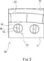
- FIG. 1 and 2 are a top view and an enlarged top view, respectively, for explaining a magnet arranging jig according to an embodiment.
- a case where the magnet arranging jig and the magnet arranging method according to the present embodiment are applied to manufacture of a rotor will be described as an example. The method can also be used for other than manufacturing rotors.
- the magnet arranging jig 10 is arranged on the inner peripheral side of the rotor 20 .
- the magnet arranging jig 10 is used to arrange a plurality of magnetized magnets 22 in the circumferential direction of the rotor 20 .
- the rotor 20 has an outer ring 21 , and a plurality of magnetized magnets 22 (hereinafter simply referred to as magnets) are arranged on the inner circumference side of the outer ring 21 . That is, the plurality of magnets 22 are inserted in the vertical direction (perpendicular to the plane of the drawing) so as to line up in the circumferential direction on the inner peripheral side of the outer peripheral ring 21 .
- the magnetized magnet 22 is a magnetized permanent magnet.
- the plurality of magnets 22 are arranged along the circumferential direction of the outer ring 21 so as to form a Halbach array.
- the magnet arranging jig 10 is substantially ring-shaped and arranged on the inner peripheral side of the rotor 20 .
- the magnet arranging jig 10 includes a jig body portion 11 and a magnetic force portion 12 .
- the jig main body 11 is configured using a non-magnetic material. That is, the jig main body 11 is configured using a non-magnetic material so that a magnetic force does not act between the jig main body 11 and the magnets 22 when the magnets 22 are arranged.
- the jig main body 11 can be made of, for example, aluminum, copper, stainless steel, or the like.
- the magnetic force part 12 is provided so as to extend in the vertical direction in the jig body part 11 .
- the magnetic force section 12 is arranged at a position facing the magnets 22 when the magnets 22 are arranged, and is configured to give the arranged magnets 22 a magnetic force that cancels the force acting on the arranged magnets 22.
- the force acting on the arrayed magnets 22 is the force caused by the magnets surrounding the arrayed magnets 22 .
- the magnetic force part 12 is arranged at a position facing the magnets 22 when the magnets 22 are arranged, and is configured to give the magnets 22 a magnetic force that attracts the magnets 22 .
- the magnetic force portion 12 is provided so as to extend in the vertical direction at a portion of the jig body portion 11 adjacent to the inner peripheral surface of the rotor 20 . At this time, the magnetic force part 12 is arranged so as to face the arrayed magnets 22 .
- the configuration example shown in FIG. 1 shows a configuration in which the magnetic force portions 12 are provided so as to face each magnet 22 (that is, a configuration in which the magnets 22 and the magnetic force portions 12 are one-to-one).
- the number of magnetic force portions 12 may be less than the number of magnets 22 .
- the position of the magnetic force portion 12 may be adjusted by rotating the jig body portion 11 to move it relative to the inner peripheral surface of the rotor 20 .
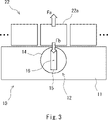
- the magnetic force portion 12 is configured to be able to change the magnetic force direction of the magnetic force portion 12 by rotating it around a rotating shaft 16 (see FIG. 2) extending in the vertical direction. For example, after arranging the magnets 22 , by rotating the magnetic force section 12 around the rotating shaft 16 , the arranged magnets 22 can be moved in the horizontal direction (the circumferential direction of the rotor 20 ).
- the magnetic force section 12 includes a cylindrical structure 14 extending in the vertical direction (the direction perpendicular to the paper surface of FIG. 2) and a vertical direction inside the cylindrical structure 14. It can be configured using a rectangular parallelepiped magnet 15 extending to the .
- the magnets 15 on the magnet arranging jig 10 side are arranged so as to face the magnets 22 on the rotor 20 side (positions corresponding to the magnets 22 to be arranged).
- the force exerted on the magnets 22 to be arranged due to the surrounding magnets can be canceled by using the magnetic force portion 12 (magnets 15), so that the assembling property of the magnets when inserting the magnets 22 can be improved. can be improved.
- the magnetic force section 12 may be configured to be removable from the jig main body section 11 .
- the magnetic force portion 12 can be configured to be inserted into a vertically extending hole formed in the jig main body portion 11 .
- the magnetic force portion 12 is rotated around the rotating shaft 16 so that the magnet 22 on the rotor 20 side and the magnetic force portion 12 of the magnet arranging jig 10 are separated from each other.
- the magnet arranging jig 10 may be removed from the rotor 20 after stopping the magnetic force from acting (that is, preventing attraction).
- FIG. 3 For example, in the examples shown in FIGS. 3 and 4, a plurality of magnets 22 form a Halbach array.
- a Halbach array is an arrangement of magnets with their magnetic poles tilted.
- the Halbach array is not limited to the configuration in which the direction of the magnetic poles is inclined by 90 degrees. Arranged configurations may also be used.
- the magnet 22a receives a magnetic force Fa from the surrounding magnets in a direction away from the magnet arranging jig 10.
- FIG. 3 the example shown in FIG.
- the magnetic force part 12 of the magnet arranging jig 10 is arranged at a position facing the arranged magnets 22a. Then, the magnets 22a are arranged (that is, the magnets 22a are inserted between adjacent magnets) in a state where the magnetic force portion 12 is arranged. At this time, the magnetic force part 12 is arranged so as to apply to the arrayed magnets 22a a magnetic force that cancels the force acting on the arrayed magnets 22a.
- the magnetic force unit 12 applies a magnetic force Fb that attracts the arranged magnet 22a to the arranged magnet 22a. placed in That is, the magnetic force part 12 is arranged so as to give the arrayed magnets 22a a magnetic force Fb that opposes the force Fa that the arrayed magnets 22a receive from surrounding magnets.
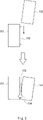
- the magnetic force portion 12 (magnets 15) is rotated around a rotating shaft 16 extending in the vertical direction, and the magnets 22a after arrangement are rotated. It can be moved horizontally. As described above, in the present embodiment, after arranging the magnets 22a, by rotating the magnetic force unit 12, the arranged magnets 22a can be moved in the horizontal direction. The position can be easily adjusted.
- the configuration (combination) of the magnets 22a and the magnetic force portion 12 can be arbitrarily determined as long as the force acting on the arrayed magnets 22a can be canceled using the magnetic force portion 12.
- 3 and 4 show only one magnetic force portion 12 for the sake of simplification of the drawings.
- the magnets 22a are arranged.
- the magnetic force part 12 is arranged so as to apply to the arrayed magnets 22a a magnetic force that cancels the force acting on the arrayed magnets 22a.
- the magnets can be arranged while canceling the magnetic force acting on the arranged magnets, so that the assembling property of the magnets can be improved.
- the magnetic force section 12 is arranged to give the magnets 22a a magnetic force that attracts the arrayed magnets 22a.
- the magnet 22a is inserted while the magnet 22a and the magnetic force portion 12 of the magnet arranging jig 10 are attracted to each other. Therefore, since the magnet 22a can be inserted while canceling the magnetic force acting on the magnet 22a generated by the surrounding magnets, the assembling property of the magnet can be improved.
- the magnets 22a can be prevented from coming into contact with other members when the magnets 22a are arranged, the coating covering the surface of the magnets 22a can be prevented from being damaged.
- the magnets 22a after being arranged can be moved in the horizontal direction by rotating the magnetic force section 12 around the rotating shaft 16. .
- the magnets 22a after arrangement can be moved in the horizontal direction by rotating the magnetic force unit 12. Therefore, the positions of the magnets 22a after arrangement in the horizontal direction can be changed. Can be easily adjusted.
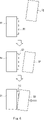
- FIG. 5 is a schematic diagram for explaining a conventional magnet arrangement method, and shows magnets 151 and 152 as seen from the inner circumference side of the rotor.
- the conventional magnet arrangement method when the magnet 152 is inserted with the adhesive 153 applied to the side surface of one of the magnets 151 , the adhesive 153 applied to the side surface of the magnet 151 is scraped off by the magnet 152 . ), and an adhesive puddle 154 may occur. Therefore, there is a problem that the magnet 151 and the magnet 152 are not adhered with the adhesive 153 in some areas.
- the magnet 52 is inserted with a sufficient gap between the magnet 52 and the magnet 52 . After that, the magnet 52 is moved to the magnet 51 side by rotating the magnetic force portion 12 of the magnet arranging jig 10 , and the magnets 51 and 52 are adhered using the adhesive 53 . Therefore, it is possible to prevent the adhesive 53 from being scraped off when inserting the magnet 52 , and the magnets 51 and 52 can be firmly adhered using the adhesive 53 .
- the present invention is not limited to the above embodiments, and can be modified as appropriate without departing from the scope of the invention.
- the magnetic force part 12 included in the magnet arranging jig 10 may be configured using a permanent magnet, or may be configured using an electromagnet.
- the rotor described in the above embodiment is of the outer rotor type, the present invention can also be applied to an inner rotor type rotor.
- the present invention has been described in accordance with the above embodiments, but the present invention is not limited only to the configurations of the above embodiments, and is applicable within the scope of the invention of the claims of the present application. Needless to say, it includes various modifications, modifications, and combinations that can be made by a trader.
Landscapes
- Engineering & Computer Science (AREA)
- Power Engineering (AREA)
- Manufacturing & Machinery (AREA)
- Permanent Field Magnets Of Synchronous Machinery (AREA)
Abstract
Description
図1、図2はそれぞれ、実施の形態にかかる磁石配列用治具を説明するための上面図、及び拡大上面図である。なお、以下では本実施の形態にかかる磁石配列用治具、及び磁石配列方法をロータの製造に適用した場合を例として説明するが、本実施の形態にかかる磁石配列用治具、及び磁石配列方法は、ロータの製造以外にも用いることができる。
11 治具本体部
12 磁力部
14 円筒状の構造体
15 磁石
16 回転軸
20 ロータ
21 外周リング
22、22a 着磁済みの磁石
51、52 磁石
53 接着剤
Claims (8)
- 複数の着磁済みの磁石を磁石配列用治具を用いて配列する磁石配列方法であって、
配列する磁石と対向する位置に、前記磁石配列用治具の磁力部を配置する工程と、
前記磁石を配列する工程と、を備え、
前記磁力部は、周囲の磁石に起因して生じる前記配列する磁石に働く力をキャンセルする磁力を前記配列する磁石に与えるように配置される、
磁石配列方法。 - 前記配列する磁石は、前記周囲の磁石から前記磁石配列用治具から離れる方向に磁力を受け、
前記磁力部は、前記配列する磁石と引き合うような磁力を前記配列する磁石に与えるように配置される、
請求項1に記載の磁石配列方法。 - 前記磁力部は鉛直方向に伸びるように設けられており、
前記磁石は前記磁石を配列する際に鉛直方向に挿入され、
前記磁石を配列した後、前記磁力部を鉛直方向に伸びる回転軸を中心に回転させて、前記配列した磁石を水平方向に移動させる工程を更に備える、
請求項2に記載の磁石配列方法。 - 前記複数の磁石はハルバッハ配列を形成している、請求項1~3のいずれか一項に記載の磁石配列方法。
- 請求項1~4のいずれか一項に記載の磁石配列方法を用いて、複数の着磁済み磁石をロータの周方向に配列する、ロータの製造方法。
- 複数の着磁済みの磁石を配列するための磁石配列用治具であって、
非磁性体を用いて構成された治具本体部と、
前記治具本体部において鉛直方向に伸びるように設けられた磁力部と、を備え、
前記磁力部は、前記磁石を配列する際に前記磁石と対向する位置に配置され、周囲の磁石に起因して生じる前記配列する磁石に働く力をキャンセルする磁力を前記配列する磁石に与えるように構成されている、
磁石配列用治具。 - 前記磁力部は、鉛直方向に伸びる回転軸を中心に回転させることで前記磁力部の磁力方向を変更可能に構成されている、請求項6に記載の磁石配列用治具。
- 前記磁力部は、
鉛直方向に伸びる円筒状の構造体と、
前記円筒状の構造体の内部に設けられた鉛直方向に伸びる直方体状の磁石と、を備える、
請求項6または7に記載の磁石配列用治具。
Priority Applications (3)
| Application Number | Priority Date | Filing Date | Title |
|---|---|---|---|
| US18/548,249 US20240235341A9 (en) | 2021-03-18 | 2022-02-02 | Magnet array method, method of manufacturing rotor, and magnet array jig |
| JP2023506837A JP7501783B2 (ja) | 2021-03-18 | 2022-02-02 | 磁石配列方法、ロータの製造方法、及び磁石配列用治具 |
| CN202280021486.XA CN116998094A (zh) | 2021-03-18 | 2022-02-02 | 磁铁排列方法、转子的制造方法以及磁铁排列用夹具 |
Applications Claiming Priority (2)
| Application Number | Priority Date | Filing Date | Title |
|---|---|---|---|
| JP2021044584 | 2021-03-18 | ||
| JP2021-044584 | 2021-03-18 |
Publications (1)
| Publication Number | Publication Date |
|---|---|
| WO2022196147A1 true WO2022196147A1 (ja) | 2022-09-22 |
Family
ID=83320307
Family Applications (1)
| Application Number | Title | Priority Date | Filing Date |
|---|---|---|---|
| PCT/JP2022/003938 Ceased WO2022196147A1 (ja) | 2021-03-18 | 2022-02-02 | 磁石配列方法、ロータの製造方法、及び磁石配列用治具 |
Country Status (4)
| Country | Link |
|---|---|
| US (1) | US20240235341A9 (ja) |
| JP (1) | JP7501783B2 (ja) |
| CN (1) | CN116998094A (ja) |
| WO (1) | WO2022196147A1 (ja) |
Cited By (1)
| Publication number | Priority date | Publication date | Assignee | Title |
|---|---|---|---|---|
| DE102024102744A1 (de) * | 2024-01-31 | 2025-07-31 | Bayerische Motoren Werke Aktiengesellschaft | Apparatur und Verfahren zur Herstellung einer Magnet-Anordnung |
Citations (6)
| Publication number | Priority date | Publication date | Assignee | Title |
|---|---|---|---|---|
| JPS62189953A (ja) * | 1986-02-14 | 1987-08-19 | Fanuc Ltd | デイスク状同期電動機のロ−タの製作法 |
| JP2010098783A (ja) * | 2008-10-14 | 2010-04-30 | Nippon Densan Corp | モータの製造方法、及びモータ |
| JP2010200518A (ja) * | 2009-02-26 | 2010-09-09 | Shin-Etsu Chemical Co Ltd | 永久磁石回転機用回転盤及び永久磁石回転機の製造方法 |
| WO2013008284A1 (ja) * | 2011-07-08 | 2013-01-17 | 三菱電機株式会社 | 永久磁石型回転電機およびその製造方法 |
| JP2013198259A (ja) * | 2012-03-19 | 2013-09-30 | Yaskawa Electric Corp | ロータ製造装置、ロータ製造方法および永久磁石位置決め方法 |
| JP2021022967A (ja) * | 2019-07-25 | 2021-02-18 | 三菱電機株式会社 | ロータ製造装置およびロータ製造方法 |
-
2022
- 2022-02-02 US US18/548,249 patent/US20240235341A9/en active Pending
- 2022-02-02 CN CN202280021486.XA patent/CN116998094A/zh active Pending
- 2022-02-02 JP JP2023506837A patent/JP7501783B2/ja active Active
- 2022-02-02 WO PCT/JP2022/003938 patent/WO2022196147A1/ja not_active Ceased
Patent Citations (6)
| Publication number | Priority date | Publication date | Assignee | Title |
|---|---|---|---|---|
| JPS62189953A (ja) * | 1986-02-14 | 1987-08-19 | Fanuc Ltd | デイスク状同期電動機のロ−タの製作法 |
| JP2010098783A (ja) * | 2008-10-14 | 2010-04-30 | Nippon Densan Corp | モータの製造方法、及びモータ |
| JP2010200518A (ja) * | 2009-02-26 | 2010-09-09 | Shin-Etsu Chemical Co Ltd | 永久磁石回転機用回転盤及び永久磁石回転機の製造方法 |
| WO2013008284A1 (ja) * | 2011-07-08 | 2013-01-17 | 三菱電機株式会社 | 永久磁石型回転電機およびその製造方法 |
| JP2013198259A (ja) * | 2012-03-19 | 2013-09-30 | Yaskawa Electric Corp | ロータ製造装置、ロータ製造方法および永久磁石位置決め方法 |
| JP2021022967A (ja) * | 2019-07-25 | 2021-02-18 | 三菱電機株式会社 | ロータ製造装置およびロータ製造方法 |
Cited By (1)
| Publication number | Priority date | Publication date | Assignee | Title |
|---|---|---|---|---|
| DE102024102744A1 (de) * | 2024-01-31 | 2025-07-31 | Bayerische Motoren Werke Aktiengesellschaft | Apparatur und Verfahren zur Herstellung einer Magnet-Anordnung |
Also Published As
| Publication number | Publication date |
|---|---|
| CN116998094A (zh) | 2023-11-03 |
| JP7501783B2 (ja) | 2024-06-18 |
| JPWO2022196147A1 (ja) | 2022-09-22 |
| US20240136897A1 (en) | 2024-04-25 |
| US20240235341A9 (en) | 2024-07-11 |
Similar Documents
| Publication | Publication Date | Title |
|---|---|---|
| JP2007014110A (ja) | 回転電機 | |
| JP6021459B2 (ja) | ステッピングモータ、レンズ装置、および、撮像装置 | |
| JP2007267565A (ja) | コアレスモータ | |
| JP2014236576A (ja) | インナーロータ型モータ | |
| WO2022196147A1 (ja) | 磁石配列方法、ロータの製造方法、及び磁石配列用治具 | |
| JPWO2007083724A1 (ja) | ギャップワインディング形モータ | |
| JP5745347B2 (ja) | ロータ及びモータ | |
| JP5359452B2 (ja) | ブラシレスモータ | |
| JP2012034458A (ja) | アキシャルギャップモータ | |
| JP6593881B2 (ja) | アキシャルギャップ型回転電機の製造方法 | |
| JP4965968B2 (ja) | アキシャルギャップ形コアレスモータおよび位置決め装置 | |
| JP7149497B2 (ja) | ブラシレスモータ及びブラシレスモータの製造方法 | |
| US12348086B2 (en) | Magnet arrangement method and rotor manufacturing method | |
| JP5300381B2 (ja) | 直流直巻モータおよびスタータ | |
| JP2022152554A (ja) | モータ | |
| US4914334A (en) | Permanent magnet DC machine | |
| JP6192788B2 (ja) | ステッピングモータ、レンズ装置、および、撮像装置 | |
| JPH1028356A (ja) | 回転電機の磁石式固定子の着磁方法 | |
| EP4443701A1 (en) | Stator, motor, and generator | |
| US20250062670A1 (en) | Interaction force control device, electromagnetic brake including the same, and rotary electric machine including the same | |
| KR100256785B1 (ko) | 영구자석형 전동기 | |
| US12500478B2 (en) | Rotator | |
| JP2021087227A (ja) | アウターロータ形電動機、及びアウターロータ形電動機のロータヨークの製造方法 | |
| JP2017060227A (ja) | 電磁モータ及び光学装置 | |
| WO2023021964A1 (ja) | 回転電機 |
Legal Events
| Date | Code | Title | Description |
|---|---|---|---|
| 121 | Ep: the epo has been informed by wipo that ep was designated in this application |
Ref document number: 22770909 Country of ref document: EP Kind code of ref document: A1 |
|
| WWE | Wipo information: entry into national phase |
Ref document number: 2023506837 Country of ref document: JP |
|
| WWE | Wipo information: entry into national phase |
Ref document number: 18548249 Country of ref document: US |
|
| WWE | Wipo information: entry into national phase |
Ref document number: 202280021486.X Country of ref document: CN |
|
| NENP | Non-entry into the national phase |
Ref country code: DE |
|
| 122 | Ep: pct application non-entry in european phase |
Ref document number: 22770909 Country of ref document: EP Kind code of ref document: A1 |