WO2022195673A1 - ガス検知器 - Google Patents
ガス検知器 Download PDFInfo
- Publication number
- WO2022195673A1 WO2022195673A1 PCT/JP2021/010369 JP2021010369W WO2022195673A1 WO 2022195673 A1 WO2022195673 A1 WO 2022195673A1 JP 2021010369 W JP2021010369 W JP 2021010369W WO 2022195673 A1 WO2022195673 A1 WO 2022195673A1
- Authority
- WO
- WIPO (PCT)
- Prior art keywords
- gas
- light
- gas detector
- detected
- detection
- Prior art date
- Legal status (The legal status is an assumption and is not a legal conclusion. Google has not performed a legal analysis and makes no representation as to the accuracy of the status listed.)
- Ceased
Links
Images




Classifications
-
- G—PHYSICS
- G01—MEASURING; TESTING
- G01N—INVESTIGATING OR ANALYSING MATERIALS BY DETERMINING THEIR CHEMICAL OR PHYSICAL PROPERTIES
- G01N21/00—Investigating or analysing materials by the use of optical means, i.e. using sub-millimetre waves, infrared, visible or ultraviolet light
- G01N21/17—Systems in which incident light is modified in accordance with the properties of the material investigated
- G01N21/25—Colour; Spectral properties, i.e. comparison of effect of material on the light at two or more different wavelengths or wavelength bands
- G01N21/31—Investigating relative effect of material at wavelengths characteristic of specific elements or molecules, e.g. atomic absorption spectrometry
- G01N21/35—Investigating relative effect of material at wavelengths characteristic of specific elements or molecules, e.g. atomic absorption spectrometry using infrared light
- G01N21/3504—Investigating relative effect of material at wavelengths characteristic of specific elements or molecules, e.g. atomic absorption spectrometry using infrared light for analysing gases, e.g. multi-gas analysis
-
- G—PHYSICS
- G01—MEASURING; TESTING
- G01N—INVESTIGATING OR ANALYSING MATERIALS BY DETERMINING THEIR CHEMICAL OR PHYSICAL PROPERTIES
- G01N33/00—Investigating or analysing materials by specific methods not covered by groups G01N1/00 - G01N31/00
- G01N33/0004—Gaseous mixtures, e.g. polluted air
- G01N33/0009—General constructional details of gas analysers, e.g. portable test equipment
- G01N33/0062—General constructional details of gas analysers, e.g. portable test equipment concerning the measuring method or the display, e.g. intermittent measurement or digital display
-
- G—PHYSICS
- G01—MEASURING; TESTING
- G01N—INVESTIGATING OR ANALYSING MATERIALS BY DETERMINING THEIR CHEMICAL OR PHYSICAL PROPERTIES
- G01N2201/00—Features of devices classified in G01N21/00
- G01N2201/02—Mechanical
- G01N2201/022—Casings
- G01N2201/0221—Portable; cableless; compact; hand-held
Definitions
- the present invention relates to gas detectors.
- Gas detectors are known that detect gases such as methane gas using infrared laser light as detection light or measure the column density of the gas. Such a gas detector emits infrared laser light, but since the infrared laser light is invisible light, the user of the gas detector cannot visually recognize the irradiation position of the infrared laser light. Therefore, there is also known a gas detector configured to emit visible laser light so that its optical axis coincides with the optical axis of infrared laser light (see, for example, Patent Document 1). According to this, the irradiation position of the visible laser light substantially coincides with the irradiation position of the infrared laser light. Therefore, the user can know the irradiation position of the infrared laser light from the irradiation position of the visible laser light.
- the conventional gas detector emits visible laser light so that the user can know the irradiation position of the infrared laser light. It may be difficult for the user to visually recognize the irradiation position of the visible laser light.
- an object of the present invention is to provide a gas detector that allows the user to grasp the irradiation position of the detection light well.
- a further object of the present invention is to centrally manage information such as the location and amount of leakage of the gas to be detected, and the date of detection of the leakage, at the time of detection of the leakage of the gas to be detected.
- a gas detector comprises a detection light emitting device that emits detection light for detecting gas, a light receiving device that receives reflected light of the detection light, and information on the reflected light received by the light receiving device. and a control unit for detecting a gas existing on the optical path of the detection light.
- the gas detector according to the present invention displays a camera device having an optical axis that substantially coincides with the optical axis of the detection light emitted by the detection light emitting device, and a camera image captured by the camera device.
- the gas detector according to the present invention may include a guide light emitting device that emits guide light having an optical axis that substantially coincides with the optical axis of the detection light.
- the guide light is, for example, visible light.
- control section is configured to display information on the detected gas on the display device when detecting a gas existing on the optical path of the detection light. good too.
- control section may be configured to display a detection result regarding the gas as information regarding the gas on the display device.
- control section may be configured to display the column density of the gas on the display device as the detection result of the gas.
- the detection light emitting device emits infrared laser light as the detection light, for example.
- a camera image when the gas is detected and information about the detected gas may be stored in a storage device. gas detector.
- the camera device images the irradiation position of the detection light and its surroundings. Therefore, the irradiation position image is displayed on the display device so as to be superimposed on the image of the irradiation position of the detection light and its surroundings. Therefore, the user of the gas detector can satisfactorily grasp the irradiation position of the detection light from the display of the display device.
- the present invention when a gas leak is detected by a gas detector, information such as the location of the gas leak, the amount of leak, and the date of detection of the leak are centrally collected.
- the quality of maintenance work can be improved.
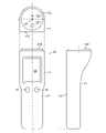
- FIG. 1 is a diagram showing a gas detector and its constituent elements according to an embodiment of the present invention.
- FIG. 2 is a diagram showing a gas detector and its components according to an embodiment of the invention.
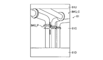
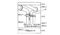
- FIG. 3 is a view showing the display of the gas detector display device according to the embodiment of the present invention.
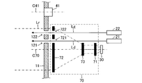
- FIG. 4 is a diagram showing the optical system and the like of the gas detector according to the embodiment of the present invention.
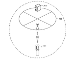
- FIG. 5 is a diagram showing a gas detector, a storage device, etc. according to an embodiment of the present invention.
- FIG. 6 is a view similar to FIG. 3 showing the display when the gas detector is powered on;
- FIG. 7 is a view similar to FIG. 3, showing the display when gas detection is taking place;
- FIG. 8 is a view similar to FIG. 3, showing a display when the gas to be detected is detected.
- FIG. 9 is a diagram showing a display displaying camera image information and detected gas information acquired from a storage device.
- FIG. 1 shows a gas detector 10 according to an embodiment of the invention.
- the gas detector 10 is a device that detects a predetermined gas (gas to be detected).
- the gas detector 10 includes a light emitting device 20, a light receiving device 30, a camera device 40, a power button 51, a detection button 52, a display device 60, a communication device 80, and an electronic control device as a control unit. 90 (hereinafter “ECU 90”).
- ECU 90 an electronic control device as a control unit. 90
- a detection light radiation opening 121, a guide light radiation opening 122 and a camera lens opening 123 are formed in the tip surface 11E of the main body 11 of the gas detector 10.
- the guide light emission aperture 122 is formed on the front face 11F side of the gas detector 10 with respect to the detection light emission aperture 121
- the camera lens aperture 123 is formed with respect to the detection light emission aperture 121. It is formed on the side opposite to the opening 122 .
- the gas detector 10 has an optical system 70 .
- the light emitting device 20 is arranged in the body 11 of the gas detector 10 and comprises a detection light emitting device 21 and a guiding light emitting device 22 .
- the detection light emitting device 21 emits detection light Ld for detecting a gas to be detected (gas to be detected by the gas detector 10).
- the gas to be detected is methane gas, but it may be hydrogen sulfide.
- the detection light Ld is, for example, frequency-modulated laser light.
- a second harmonic signal corresponding to the gas concentration is generated.
- the wavelength (frequency) of the detection light Ld is preferably a wavelength that is absorbed by the gas to be detected but is not absorbed by the background gas (gas such as water vapor other than the gas to be detected).
- the gas to be detected is methane gas
- an infrared laser beam with an oscillation wavelength in the 1.65 ⁇ m band is used as the detection light Ld.
- the gas to be detected is hydrogen sulfide gas
- an infrared laser beam with an oscillation wavelength in the 1.57 ⁇ m band is used as the detection light Ld.
- the detection light emitting device 21 is electrically connected to the ECU 90.
- the ECU 90 can cause the detection light emitting device 21 to emit the detection light Ld or stop emitting the detection light Ld.
- the gas to be detected is methane gas
- the detection light Ld is an invisible infrared laser beam. The position where the detection light Ld is irradiated) cannot be visually recognized.
- the guide light emitting device 22 emits guide light Lg for indicating the irradiation position of the detection light Ld (the position where the detection light Ld is irradiated).
- the guide light Lg is visible light such as red or green semiconductor laser light.
- the guide light emitting device 22 is arranged to emit the guide light Lg so that the optical axis of the guide light Lg substantially coincides with the optical axis of the detection light Ld. Therefore, the irradiation position of the guide light Lg (the position where the guide light Lg is irradiated) substantially coincides with the irradiation position of the detection light Ld. Therefore, the user of the gas detector 10 can know the irradiation position of the detection light Ld from the irradiation position of the guide light Lg.
- the guide light emitting device 22 is electrically connected to the ECU 90.
- the ECU 90 can cause the guide light emitting device 22 to emit the guide light Lg or stop emitting the guide light Lg.
- a semiconductor laser oscillator is used for the detection light emitting device 21
- a standard cell filled with the gas to be detected is prepared, and the light absorption in the standard cell is referred to, so that the oscillation wavelength of the detection light Ld is adjusted to the absorption of the gas to be detected. It is preferable to adjust the operating temperature and the like of the semiconductor laser oscillator so that the center of the line is aligned.
- the optical system 70 is a device that converges detection light Ld (reflected light Lr) reflected by an object.
- the optical system 70 comprises a plurality of optical elements, namely a first optical element 71, a second optical element 72 and a third optical element 73, as shown in FIG.
- reference numeral C70 indicates the optical axis of the optical system 70. As shown in FIG.
- the first optical element 71 is arranged closest to the light receiving device 30 .
- the first optical element 71 is a condensing element that converges parallel light onto the light receiving device 30 .
- the second optical element 72 is arranged furthest from the light receiving device 30 .
- the second optical element 72 has an aperture diameter larger than that of the first optical element 71 .
- the second optical element 72 is a condensing element that converges parallel light incident on the optical system 70 .
- the third optical element 73 is arranged between the first optical element 71 and the second optical element 72 .
- the third optical element 73 is a light scattering element that diverges the light converged by the second optical element 72 into parallel light.
- the third optical element 73 is a single optical element, but may be an optical element configured by combining a plurality of optical elements.
- the second optical element 72 is arranged at a position that blocks the optical path of the detection light Ld and the optical path of the guide light Lg. 721 and guide light passage holes 722 for passing the guide light Lg are respectively formed.
- the detection light emitting device 21 is arranged so that the emitted detection light Ld is emitted outside the gas detector 10 through the detection light passage hole 721 and the detection light emission opening 121 .
- the guide light emitting device 22 is arranged so that the emitted guide light Lg is emitted outside the gas detector 10 through the guide light passing hole 722 and the guide light emitting opening 122 .
- the detection light Ld emitted from the detection light emitting device 21 is emitted outside the gas detector 10 through the detection light passage hole 721 and the detection light emission opening 121, and emitted from the guide light emitting device 22.
- the guide light Lg is emitted outside the gas detector 10 through the guide light passage hole 722 and the guide light emission opening 122 .
- the aperture diameter of the second optical element 72 is larger than the aperture diameter of the first optical element 71, more reflected light Lr is collected, the collected reflected light Lr is converged, and the intensity is increased. A large amount of light can be incident on the light receiving device 30 . Therefore, information such as the column density of the gas to be detected can be obtained with higher sensitivity.
- the column density of the gas to be detected is the integrated value of the concentration of the gas to be detected existing on the optical path of the detection light Ld (and the reflected light Lr).
- At least one (preferably all) of the optical elements of the optical system 70 may be a Fresnel lens. According to this, the weight of the optical system 70 can be reduced, and as a result, the weight of the gas detector 10 can be reduced.
- the light receiving device 30 is a device that receives the reflected light Lr converged by the optical system 70 and outputs a signal (light receiving signal) corresponding to the intensity of the received reflected light Lr.
- the light receiving device 30 is composed of, for example, a photoelectric conversion element such as a photodiode or a photomultiplier, and a driving/detecting circuit thereof.
- the light receiving device 30 may include an optical filter such as a bandpass filter, a slit, a spectroscopic mechanism, and the like.
- the light receiving device 30 is electrically connected to the ECU 90 .
- the light receiving device 30 transmits a light receiving signal to the ECU 90 .
- the ECU 90 can obtain information about the gas to be detected present on the optical path of the detection light Ld based on the received light signal.
- the camera device 40 is a device that captures an image of the outside of the gas detector 10 and outputs the captured image (camera image).
- the camera device 40 includes a camera 41 such as a CCD camera.
- the camera device 40 is arranged so that the outside of the gas detector 10 can be imaged by the camera 41 through the camera lens opening 123 .
- the camera device 40 is arranged so that the optical axis C41 of the camera 41 substantially coincides with the optical axis of the detection light Ld. Accordingly, the camera device 40 captures an image of the periphery of the irradiation position of the detection light Ld with the camera 41 .
- the camera device 40 is electrically connected to the ECU 90.
- the camera device 40 transmits (data of) an image captured by the camera 41 to the ECU 90 .
- the display device 60 is a device that displays various images.
- the display device 60 includes a display 61 such as a liquid crystal display.
- the display device 60 is arranged at a position where the display 61 can be visually recognized by the user.
- the display device 60 is provided so that the display 61 is exposed to the outside on the front face 11F of the main body 11 of the gas detector 10 .
- the display device 60 is electrically connected to the ECU 90.
- the ECU 90 can cause the display device 60 to display various images.
- the power button 51 is a device operated by the user to turn on or off the power of the gas detector 10 .
- the detection button 52 is a device operated by the user to start and end gas detection, which will be described later.
- the power button 51 and the detection button 52 are provided on the front surface 11F of the main body 11 of the gas detector 10 so as to be exposed to the outside.
- the power button 51 and the detection button 52 are electrically connected to the ECU 90.
- the ECU 90 turns on or off the gas detector 10 .
- the detection button 52 is operated by the user, the ECU 90 starts and ends gas detection.
- the communication device 80 is a device that communicates via the Internet 200 with a storage device 201 such as a server and cloud located on the Internet 200 (see FIG. 5).
- Communication device 80 is electrically connected to ECU 90 . Therefore, the ECU 90 can communicate with the storage device 201 arranged on the Internet 200 via the communication device 80 .
- the ECU 90 turns on the power of the gas detector 10 and starts imaging with the camera device 40, as shown in FIG. , the image (camera image IMG_C) transmitted from the camera device 40 is displayed in the central region 61C of the display 61, and information such as the remaining charge of the battery mounted in the gas detector 10 is displayed on the display 61. It is displayed in the upper area 61U.
- the ECU 90 starts detection of the gas to be detected (gas detection).
- the ECU 90 When starting gas detection, the ECU 90 emits the detection light Ld from the detection light emitting device 21 .
- the detection light Ld emitted from the detection light emitting device 21 passes through the detection light passage hole 721 and the detection light emission opening 121 in order and is emitted outside the gas detector 10 .
- the detection light Ld emitted outside the gas detector 10 is applied to an object.
- the ECU 90 causes the guide light emitting device 22 to emit the guide light Lg.
- the guide light Lg emitted from the guide light emitting device 22 passes through the guide light passing hole 722 and the guide light emitting opening 122 in order and is emitted outside the gas detector 10 .
- the guide light Lg emitted to the outside of the gas detector 10 is applied to an object.
- the ECU 90 when starting gas detection, the ECU 90 superimposes the irradiation position image IMG_P on the camera image IMG_C and displays it in the center of the central region 61C of the display 61, as shown in FIG.
- the irradiation position image IMG_P is an image representing the irradiation position of the guide light Lg (that is, the irradiation position of the detection light Ld).
- the detection light Ld irradiated to the object is reflected by the object.
- the detection light Ld (reflected light Lr) reflected by the object is received by the light receiving device 30 .
- the light receiving device 30 transmits a light reception signal to the ECU 90 according to the intensity of the received reflected light Lr.
- the ECU 90 acquires information about light absorption by the gas to be detected contained in the reflected light Lr from the received light reception signal, and detects the gas to be detected on the optical path of the detection light Ld from the information.
- the ECU 90 detects a "fundamental wave signal with a frequency equal to the modulation frequency of the detection light Ld" and a "double wave signal with a frequency twice the modulation frequency of the detection light Ld" from the received light signal. do. Synchronous detection can be used to detect the fundamental wave signal and the double wave signal. The ECU 90 detects the gas to be detected in an atmosphere containing background gas based on the ratio between the fundamental wave signal and the double wave signal.
- the ECU 90 acquires information about the gas to be detected, and displays an image representing the acquired information on the display 61 .
- the information about the gas to be detected is, for example, the result of detection about the gas to be detected, and the result of detection about the gas to be detected is, for example, the measured value of the gas to be detected, such as the column density of the gas to be detected and the concentration of the gas to be detected. be. Further, the detection result of the gas to be detected may be the detection of the gas to be detected.
- the ECU 90 when the ECU 90 detects the gas to be detected, the ECU 90 obtains the column density of the gas to be detected, and displays an image IMG_G representing the obtained column density of the gas to be detected on the display 61 as shown in FIG. is displayed in the lower area 61L.
- the irradiation position image IMG_P is displayed on the display 61 superimposed on the irradiation position of the detection light Ld and the camera image IMG_C around it. Therefore, the user of the gas detector 10 can well grasp the irradiation position of the detection light Ld from the display of the display 61, and when the column density of the gas to be detected is displayed on the display 61, the display 61 Therefore, the position where the gas to be detected exists can be well grasped.
- the gas detector 10 detects the gas to be detected, the gas detector 10 transmits information (camera image information) of the camera image IMG_C when the gas to be detected and information on the detected gas to be detected (gas information). It is stored in the storage device 201 via the communication device 80 and the Internet 200 (see FIG. 5).
- the detected gas information is the column density of the detected detected gas, the location and/or location where the detected gas is detected, and the date and time when the detected gas is detected.
- the gas detector 10 may be provided with a button or switch, and the gas detector 10 may be configured to store the camera image information and the detected gas information in the storage device 201 when the button is operated by the user. .
- the user can later use the camera image information and detected gas information stored in the storage device 201.
- the gas detector 10 is configured so as to acquire from the storage device 201 camera image information and detected gas information indicated by .
- the gas detector 10 detects the gas to be detected
- the user prints the above code on paper or a sticker, and leaves the paper or sticker where the gas to be detected is detected. Then, the user later acquires the camera image information and the detected gas information indicated by the code from the storage device 201 by causing the gas detector 10 to read the code.
- the camera image information and the detected gas information are acquired using a dedicated device having the function of reading the code and acquiring the camera image information and the detected gas information indicated by the read code from the storage device 201. can be
- the gas detector 10 When the gas detector 10 acquires the camera image information and the detected gas information, the gas detector 10 displays the camera image IMG_C indicated by the acquired camera image information on the display 61 as shown in FIG. The information is superimposed on the camera image IMG_C and displayed on the display 61 .
- the gas detector 10 has an image IMG_G representing the column density of the gas to be detected, an image IMG_D representing the date when the gas to be detected was detected, and an image representing the time when the gas to be detected was detected.
- the display 61 displays an image IMG_T and an image IMG_A representing the address of the place where the gas to be detected is detected.
- the operator can refer to the camera image information and the detected gas information stored in the storage device 201 when performing maintenance work such as repairing a gas leakage point. Therefore, the quality of maintenance work can be improved.
Landscapes
- Chemical & Material Sciences (AREA)
- Physics & Mathematics (AREA)
- Health & Medical Sciences (AREA)
- Life Sciences & Earth Sciences (AREA)
- General Physics & Mathematics (AREA)
- Analytical Chemistry (AREA)
- Biochemistry (AREA)
- General Health & Medical Sciences (AREA)
- Spectroscopy & Molecular Physics (AREA)
- Immunology (AREA)
- Pathology (AREA)
- Engineering & Computer Science (AREA)
- Combustion & Propulsion (AREA)
- Food Science & Technology (AREA)
- Medicinal Chemistry (AREA)
- Investigating Or Analysing Materials By Optical Means (AREA)
Priority Applications (3)
| Application Number | Priority Date | Filing Date | Title |
|---|---|---|---|
| PCT/JP2021/010369 WO2022195673A1 (ja) | 2021-03-15 | 2021-03-15 | ガス検知器 |
| JP2023506397A JP7469557B2 (ja) | 2021-03-15 | 2021-03-15 | ガス検知器 |
| US18/550,394 US20240159663A1 (en) | 2021-03-15 | 2021-03-15 | Gas detection device |
Applications Claiming Priority (1)
| Application Number | Priority Date | Filing Date | Title |
|---|---|---|---|
| PCT/JP2021/010369 WO2022195673A1 (ja) | 2021-03-15 | 2021-03-15 | ガス検知器 |
Publications (1)
| Publication Number | Publication Date |
|---|---|
| WO2022195673A1 true WO2022195673A1 (ja) | 2022-09-22 |
Family
ID=83320076
Family Applications (1)
| Application Number | Title | Priority Date | Filing Date |
|---|---|---|---|
| PCT/JP2021/010369 Ceased WO2022195673A1 (ja) | 2021-03-15 | 2021-03-15 | ガス検知器 |
Country Status (3)
| Country | Link |
|---|---|
| US (1) | US20240159663A1 (cg-RX-API-DMAC7.html) |
| JP (1) | JP7469557B2 (cg-RX-API-DMAC7.html) |
| WO (1) | WO2022195673A1 (cg-RX-API-DMAC7.html) |
Citations (7)
| Publication number | Priority date | Publication date | Assignee | Title |
|---|---|---|---|---|
| JP2014055858A (ja) * | 2012-09-12 | 2014-03-27 | Tokyo Metropolitan Sewerage Service Corp | ガス濃度測定装置 |
| US20150369730A1 (en) * | 2014-06-20 | 2015-12-24 | Fluke Corporation | Laser illuminated gas imaging |
| US20170284887A1 (en) * | 2016-03-31 | 2017-10-05 | Konica Minolta Laboratory U.S.A., Inc. | Laser scanning leak detection and visualization apparatus |
| US20170336281A1 (en) * | 2016-05-18 | 2017-11-23 | MultiSensor Scientific, Inc. | Hydrocarbon leak imaging and quantification sensor |
| JP2018169202A (ja) * | 2017-03-29 | 2018-11-01 | 東京ガスエンジニアリングソリューションズ株式会社 | ガス検知器 |
| WO2019049562A1 (ja) * | 2017-09-11 | 2019-03-14 | パナソニックIpマネジメント株式会社 | 物質検知装置及び物質検知方法 |
| JP2020159798A (ja) * | 2019-03-26 | 2020-10-01 | 東京瓦斯株式会社 | ガス検知装置、ガス検知方法およびガス検知システム |
Family Cites Families (1)
| Publication number | Priority date | Publication date | Assignee | Title |
|---|---|---|---|---|
| US20180284015A1 (en) | 2015-05-08 | 2018-10-04 | Konica Minolta, Inc. | Gas Concentration Measurement Device |
-
2021
- 2021-03-15 US US18/550,394 patent/US20240159663A1/en active Pending
- 2021-03-15 WO PCT/JP2021/010369 patent/WO2022195673A1/ja not_active Ceased
- 2021-03-15 JP JP2023506397A patent/JP7469557B2/ja active Active
Patent Citations (7)
| Publication number | Priority date | Publication date | Assignee | Title |
|---|---|---|---|---|
| JP2014055858A (ja) * | 2012-09-12 | 2014-03-27 | Tokyo Metropolitan Sewerage Service Corp | ガス濃度測定装置 |
| US20150369730A1 (en) * | 2014-06-20 | 2015-12-24 | Fluke Corporation | Laser illuminated gas imaging |
| US20170284887A1 (en) * | 2016-03-31 | 2017-10-05 | Konica Minolta Laboratory U.S.A., Inc. | Laser scanning leak detection and visualization apparatus |
| US20170336281A1 (en) * | 2016-05-18 | 2017-11-23 | MultiSensor Scientific, Inc. | Hydrocarbon leak imaging and quantification sensor |
| JP2018169202A (ja) * | 2017-03-29 | 2018-11-01 | 東京ガスエンジニアリングソリューションズ株式会社 | ガス検知器 |
| WO2019049562A1 (ja) * | 2017-09-11 | 2019-03-14 | パナソニックIpマネジメント株式会社 | 物質検知装置及び物質検知方法 |
| JP2020159798A (ja) * | 2019-03-26 | 2020-10-01 | 東京瓦斯株式会社 | ガス検知装置、ガス検知方法およびガス検知システム |
Also Published As
| Publication number | Publication date |
|---|---|
| JPWO2022195673A1 (cg-RX-API-DMAC7.html) | 2022-09-22 |
| US20240159663A1 (en) | 2024-05-16 |
| JP7469557B2 (ja) | 2024-04-16 |
Similar Documents
| Publication | Publication Date | Title |
|---|---|---|
| KR101716902B1 (ko) | 분광 측정 장치, 분광 측정 방법, 및 분광 측정 프로그램 | |
| RU2139571C1 (ru) | Обнаружение поддельных объектов | |
| CN101936896B (zh) | 一种乙醇气体浓度激光遥测装置 | |
| CN108061722A (zh) | 一种一氧化碳浓度的检测装置及检测方法 | |
| US20060044144A1 (en) | Substance detection and alarm using a spectrometer built into a steering wheel assembly | |
| JP2012501438A (ja) | 低濃度ガスのスペクトル分析に適合したスペクトル分析装置 | |
| KR101039135B1 (ko) | 검측지점 표시 기능을 갖는 광학용 메탄가스 검지 장치 | |
| TW201409016A (zh) | 光校正裝置、生物檢測校正系統及其操作方法 | |
| CN107860749A (zh) | 基于co2激光器的便携式sf6泄漏遥测仪 | |
| US8208982B2 (en) | Evanescent catheter system | |
| JP2008232919A (ja) | ガス検知装置 | |
| JP6364305B2 (ja) | 水素ガス濃度計測装置および方法 | |
| JP7469557B2 (ja) | ガス検知器 | |
| US20100225916A1 (en) | Liquid Immersion Type Absorbance Sensor Element and Absorption Spectrometer Using Same | |
| JPH1137930A (ja) | 吸光光度計 | |
| JP3819083B2 (ja) | 蛍光診断装置 | |
| JPH0961351A (ja) | 含水分検知装置・含水分測定方法および含水分測定装置 | |
| JPH09264845A (ja) | 吸光光度計 | |
| US20190228205A1 (en) | Skinprint analysis method and apparatus | |
| WO2014032615A1 (en) | Portable metal ion detector | |
| CN115112567A (zh) | 一种甲烷遥测装置及方法 | |
| JP2003501650A (ja) | 分光計器具のための較正モード認識と較正アルゴリズム | |
| EP0081947A1 (en) | Method and apparatus for normalizing radiometric measurements | |
| JP2004163235A (ja) | X線分析装置 | |
| CN111982851A (zh) | 酒精气体检测装置及检测方法 |
Legal Events
| Date | Code | Title | Description |
|---|---|---|---|
| 121 | Ep: the epo has been informed by wipo that ep was designated in this application |
Ref document number: 21930606 Country of ref document: EP Kind code of ref document: A1 |
|
| ENP | Entry into the national phase |
Ref document number: 2023506397 Country of ref document: JP Kind code of ref document: A |
|
| WWE | Wipo information: entry into national phase |
Ref document number: 18550394 Country of ref document: US |
|
| NENP | Non-entry into the national phase |
Ref country code: DE |
|
| 122 | Ep: pct application non-entry in european phase |
Ref document number: 21930606 Country of ref document: EP Kind code of ref document: A1 |