WO2022191069A1 - Methane production system and methane production method - Google Patents
Methane production system and methane production method Download PDFInfo
- Publication number
- WO2022191069A1 WO2022191069A1 PCT/JP2022/009406 JP2022009406W WO2022191069A1 WO 2022191069 A1 WO2022191069 A1 WO 2022191069A1 JP 2022009406 W JP2022009406 W JP 2022009406W WO 2022191069 A1 WO2022191069 A1 WO 2022191069A1
- Authority
- WO
- WIPO (PCT)
- Prior art keywords
- reforming
- electrolysis
- electrolytic
- electrode
- cell
- Prior art date
Links
- VNWKTOKETHGBQD-UHFFFAOYSA-N methane Chemical compound C VNWKTOKETHGBQD-UHFFFAOYSA-N 0.000 title claims abstract description 81
- 238000004519 manufacturing process Methods 0.000 title claims abstract description 30
- 238000005868 electrolysis reaction Methods 0.000 claims abstract description 77
- 238000002407 reforming Methods 0.000 claims description 112
- 239000003792 electrolyte Substances 0.000 claims description 23
- 239000007789 gas Substances 0.000 description 61
- 239000000758 substrate Substances 0.000 description 45
- 238000011084 recovery Methods 0.000 description 19
- 229910052760 oxygen Inorganic materials 0.000 description 14
- 238000006243 chemical reaction Methods 0.000 description 11
- CURLTUGMZLYLDI-UHFFFAOYSA-N Carbon dioxide Chemical compound O=C=O CURLTUGMZLYLDI-UHFFFAOYSA-N 0.000 description 10
- 239000001301 oxygen Substances 0.000 description 10
- -1 oxygen ions Chemical class 0.000 description 8
- 238000004891 communication Methods 0.000 description 6
- 239000000463 material Substances 0.000 description 6
- 229910002092 carbon dioxide Inorganic materials 0.000 description 5
- 229910002091 carbon monoxide Inorganic materials 0.000 description 5
- 239000002131 composite material Substances 0.000 description 5
- 238000012986 modification Methods 0.000 description 5
- 230000004048 modification Effects 0.000 description 5
- 239000011148 porous material Substances 0.000 description 5
- 230000002265 prevention Effects 0.000 description 5
- XLYOFNOQVPJJNP-UHFFFAOYSA-N water Chemical compound O XLYOFNOQVPJJNP-UHFFFAOYSA-N 0.000 description 5
- 229910001233 yttria-stabilized zirconia Inorganic materials 0.000 description 5
- UFHFLCQGNIYNRP-UHFFFAOYSA-N Hydrogen Chemical compound [H][H] UFHFLCQGNIYNRP-UHFFFAOYSA-N 0.000 description 4
- 239000003054 catalyst Substances 0.000 description 4
- 239000001257 hydrogen Substances 0.000 description 4
- 229910052739 hydrogen Inorganic materials 0.000 description 4
- 229910052746 lanthanum Inorganic materials 0.000 description 4
- CPLXHLVBOLITMK-UHFFFAOYSA-N magnesium oxide Inorganic materials [Mg]=O CPLXHLVBOLITMK-UHFFFAOYSA-N 0.000 description 4
- 229910052712 strontium Inorganic materials 0.000 description 4
- MCMNRKCIXSYSNV-UHFFFAOYSA-N Zirconium dioxide Chemical compound O=[Zr]=O MCMNRKCIXSYSNV-UHFFFAOYSA-N 0.000 description 3
- 229910002084 calcia-stabilized zirconia Inorganic materials 0.000 description 3
- 239000011247 coating layer Substances 0.000 description 3
- 238000010586 diagram Methods 0.000 description 3
- 229910021526 gadolinium-doped ceria Inorganic materials 0.000 description 3
- 239000010410 layer Substances 0.000 description 3
- 239000000395 magnesium oxide Substances 0.000 description 3
- 238000005192 partition Methods 0.000 description 3
- 239000007787 solid Substances 0.000 description 3
- 229910000859 α-Fe Inorganic materials 0.000 description 3
- 229910018072 Al 2 O 3 Inorganic materials 0.000 description 2
- 229910018921 CoO 3 Inorganic materials 0.000 description 2
- PACGUUNWTMTWCF-UHFFFAOYSA-N [Sr].[La] Chemical compound [Sr].[La] PACGUUNWTMTWCF-UHFFFAOYSA-N 0.000 description 2
- QVGXLLKOCUKJST-UHFFFAOYSA-N atomic oxygen Chemical compound [O] QVGXLLKOCUKJST-UHFFFAOYSA-N 0.000 description 2
- 229910052963 cobaltite Inorganic materials 0.000 description 2
- AXZKOIWUVFPNLO-UHFFFAOYSA-N magnesium;oxygen(2-) Chemical compound [O-2].[Mg+2] AXZKOIWUVFPNLO-UHFFFAOYSA-N 0.000 description 2
- 239000000203 mixture Substances 0.000 description 2
- PXHVJJICTQNCMI-UHFFFAOYSA-N nickel Substances [Ni] PXHVJJICTQNCMI-UHFFFAOYSA-N 0.000 description 2
- RUDFQVOCFDJEEF-UHFFFAOYSA-N yttrium(III) oxide Inorganic materials [O-2].[O-2].[O-2].[Y+3].[Y+3] RUDFQVOCFDJEEF-UHFFFAOYSA-N 0.000 description 2
- 229910003026 (La,Sr)(Co,Fe)O3 Inorganic materials 0.000 description 1
- 238000007088 Archimedes method Methods 0.000 description 1
- OKTJSMMVPCPJKN-UHFFFAOYSA-N Carbon Chemical compound [C] OKTJSMMVPCPJKN-UHFFFAOYSA-N 0.000 description 1
- UGFAIRIUMAVXCW-UHFFFAOYSA-N Carbon monoxide Chemical compound [O+]#[C-] UGFAIRIUMAVXCW-UHFFFAOYSA-N 0.000 description 1
- BVKZGUZCCUSVTD-UHFFFAOYSA-L Carbonate Chemical compound [O-]C([O-])=O BVKZGUZCCUSVTD-UHFFFAOYSA-L 0.000 description 1
- 229910017563 LaCrO Inorganic materials 0.000 description 1
- 229910020068 MgAl Inorganic materials 0.000 description 1
- 229910001252 Pd alloy Inorganic materials 0.000 description 1
- 229910052772 Samarium Inorganic materials 0.000 description 1
- QBYHSJRFOXINMH-UHFFFAOYSA-N [Co].[Sr].[La] Chemical compound [Co].[Sr].[La] QBYHSJRFOXINMH-UHFFFAOYSA-N 0.000 description 1
- UNPDDPPIJHUKSG-UHFFFAOYSA-N [Sr].[Sm] Chemical compound [Sr].[Sm] UNPDDPPIJHUKSG-UHFFFAOYSA-N 0.000 description 1
- PNEYBMLMFCGWSK-UHFFFAOYSA-N aluminium oxide Inorganic materials [O-2].[O-2].[O-2].[Al+3].[Al+3] PNEYBMLMFCGWSK-UHFFFAOYSA-N 0.000 description 1
- 229910052799 carbon Inorganic materials 0.000 description 1
- 239000001569 carbon dioxide Substances 0.000 description 1
- NFYLSJDPENHSBT-UHFFFAOYSA-N chromium(3+);lanthanum(3+);oxygen(2-) Chemical compound [O-2].[O-2].[O-2].[Cr+3].[La+3] NFYLSJDPENHSBT-UHFFFAOYSA-N 0.000 description 1
- 239000000470 constituent Substances 0.000 description 1
- 230000006866 deterioration Effects 0.000 description 1
- 238000007323 disproportionation reaction Methods 0.000 description 1
- 230000000694 effects Effects 0.000 description 1
- 239000000446 fuel Substances 0.000 description 1
- LNTHITQWFMADLM-UHFFFAOYSA-N gallic acid Chemical compound OC(=O)C1=CC(O)=C(O)C(O)=C1 LNTHITQWFMADLM-UHFFFAOYSA-N 0.000 description 1
- 239000011521 glass Substances 0.000 description 1
- 150000002500 ions Chemical class 0.000 description 1
- 229910052742 iron Inorganic materials 0.000 description 1
- FZLIPJUXYLNCLC-UHFFFAOYSA-N lanthanum atom Chemical compound [La] FZLIPJUXYLNCLC-UHFFFAOYSA-N 0.000 description 1
- DOARWPHSJVUWFT-UHFFFAOYSA-N lanthanum nickel Chemical compound [Ni].[La] DOARWPHSJVUWFT-UHFFFAOYSA-N 0.000 description 1
- 239000007788 liquid Substances 0.000 description 1
- 229910052759 nickel Inorganic materials 0.000 description 1
- KDLHZDBZIXYQEI-UHFFFAOYSA-N palladium Substances [Pd] KDLHZDBZIXYQEI-UHFFFAOYSA-N 0.000 description 1
- SWELZOZIOHGSPA-UHFFFAOYSA-N palladium silver Chemical compound [Pd].[Ag] SWELZOZIOHGSPA-UHFFFAOYSA-N 0.000 description 1
- 239000008188 pellet Substances 0.000 description 1
- 239000012466 permeate Substances 0.000 description 1
- 229910052709 silver Inorganic materials 0.000 description 1
- 239000004332 silver Substances 0.000 description 1
- 229910052596 spinel Inorganic materials 0.000 description 1
- 239000011029 spinel Substances 0.000 description 1
- VEALVRVVWBQVSL-UHFFFAOYSA-N strontium titanate Chemical compound [Sr+2].[O-][Ti]([O-])=O VEALVRVVWBQVSL-UHFFFAOYSA-N 0.000 description 1
- 239000000126 substance Substances 0.000 description 1
- 230000009466 transformation Effects 0.000 description 1
Images


Classifications
-
- C—CHEMISTRY; METALLURGY
- C25—ELECTROLYTIC OR ELECTROPHORETIC PROCESSES; APPARATUS THEREFOR
- C25B—ELECTROLYTIC OR ELECTROPHORETIC PROCESSES FOR THE PRODUCTION OF COMPOUNDS OR NON-METALS; APPARATUS THEREFOR
- C25B3/00—Electrolytic production of organic compounds
- C25B3/01—Products
- C25B3/03—Acyclic or carbocyclic hydrocarbons
-
- C—CHEMISTRY; METALLURGY
- C07—ORGANIC CHEMISTRY
- C07C—ACYCLIC OR CARBOCYCLIC COMPOUNDS
- C07C1/00—Preparation of hydrocarbons from one or more compounds, none of them being a hydrocarbon
- C07C1/02—Preparation of hydrocarbons from one or more compounds, none of them being a hydrocarbon from oxides of a carbon
- C07C1/04—Preparation of hydrocarbons from one or more compounds, none of them being a hydrocarbon from oxides of a carbon from carbon monoxide with hydrogen
-
- C—CHEMISTRY; METALLURGY
- C07—ORGANIC CHEMISTRY
- C07C—ACYCLIC OR CARBOCYCLIC COMPOUNDS
- C07C9/00—Aliphatic saturated hydrocarbons
- C07C9/02—Aliphatic saturated hydrocarbons with one to four carbon atoms
- C07C9/04—Methane
-
- C—CHEMISTRY; METALLURGY
- C25—ELECTROLYTIC OR ELECTROPHORETIC PROCESSES; APPARATUS THEREFOR
- C25B—ELECTROLYTIC OR ELECTROPHORETIC PROCESSES FOR THE PRODUCTION OF COMPOUNDS OR NON-METALS; APPARATUS THEREFOR
- C25B1/00—Electrolytic production of inorganic compounds or non-metals
- C25B1/01—Products
- C25B1/02—Hydrogen or oxygen
- C25B1/04—Hydrogen or oxygen by electrolysis of water
-
- C—CHEMISTRY; METALLURGY
- C25—ELECTROLYTIC OR ELECTROPHORETIC PROCESSES; APPARATUS THEREFOR
- C25B—ELECTROLYTIC OR ELECTROPHORETIC PROCESSES FOR THE PRODUCTION OF COMPOUNDS OR NON-METALS; APPARATUS THEREFOR
- C25B1/00—Electrolytic production of inorganic compounds or non-metals
- C25B1/01—Products
- C25B1/23—Carbon monoxide or syngas
-
- C—CHEMISTRY; METALLURGY
- C25—ELECTROLYTIC OR ELECTROPHORETIC PROCESSES; APPARATUS THEREFOR
- C25B—ELECTROLYTIC OR ELECTROPHORETIC PROCESSES FOR THE PRODUCTION OF COMPOUNDS OR NON-METALS; APPARATUS THEREFOR
- C25B15/00—Operating or servicing cells
- C25B15/02—Process control or regulation
- C25B15/021—Process control or regulation of heating or cooling
-
- C—CHEMISTRY; METALLURGY
- C25—ELECTROLYTIC OR ELECTROPHORETIC PROCESSES; APPARATUS THEREFOR
- C25B—ELECTROLYTIC OR ELECTROPHORETIC PROCESSES FOR THE PRODUCTION OF COMPOUNDS OR NON-METALS; APPARATUS THEREFOR
- C25B15/00—Operating or servicing cells
- C25B15/08—Supplying or removing reactants or electrolytes; Regeneration of electrolytes
- C25B15/087—Recycling of electrolyte to electrochemical cell
-
- C—CHEMISTRY; METALLURGY
- C25—ELECTROLYTIC OR ELECTROPHORETIC PROCESSES; APPARATUS THEREFOR
- C25B—ELECTROLYTIC OR ELECTROPHORETIC PROCESSES FOR THE PRODUCTION OF COMPOUNDS OR NON-METALS; APPARATUS THEREFOR
- C25B3/00—Electrolytic production of organic compounds
- C25B3/20—Processes
- C25B3/25—Reduction
-
- Y—GENERAL TAGGING OF NEW TECHNOLOGICAL DEVELOPMENTS; GENERAL TAGGING OF CROSS-SECTIONAL TECHNOLOGIES SPANNING OVER SEVERAL SECTIONS OF THE IPC; TECHNICAL SUBJECTS COVERED BY FORMER USPC CROSS-REFERENCE ART COLLECTIONS [XRACs] AND DIGESTS
- Y02—TECHNOLOGIES OR APPLICATIONS FOR MITIGATION OR ADAPTATION AGAINST CLIMATE CHANGE
- Y02E—REDUCTION OF GREENHOUSE GAS [GHG] EMISSIONS, RELATED TO ENERGY GENERATION, TRANSMISSION OR DISTRIBUTION
- Y02E60/00—Enabling technologies; Technologies with a potential or indirect contribution to GHG emissions mitigation
- Y02E60/30—Hydrogen technology
- Y02E60/36—Hydrogen production from non-carbon containing sources, e.g. by water electrolysis
Definitions
- the present invention relates to a methane production system and a methane production method.
- Patent Document 1 discloses a hydrogen electrode that electrolyzes H 2 O, an electrolyte capable of conducting O 2 ⁇ , and an oxygen electrode that generates O 2 from O 2 ⁇ transferred from the hydrogen electrode via the electrolyte.
- a solid oxide electrolysis cell hereinafter abbreviated as "SOEC" is disclosed.
- Patent Document 2 discloses that H 2 and CO can be produced by co-electrolyzing CO 2 and H 2 O at the hydrogen electrode of an SOEC.
- the present invention has been made in view of the circumstances described above, and an object of the present invention is to provide a methane production system and a methane production method capable of producing H 2 and CO and CH 4 on-site.
- a methane production system includes a co-electrolytic/reforming cell and a control unit that controls the operating temperature of the co-electrolytic/reforming cell.
- a co-electrolytic/reforming cell has a first electrode, a second electrode, and an electrolyte disposed between the first and second electrodes.
- the co-electrolysis/reforming cell has a co-electrolysis mode producing H2 and CO from CO2 and H2O at the first electrode and CH4 at the first electrode from H2 and CO produced in the co - electrolysis mode. It operates in either a reforming mode to produce.
- the control unit makes the operating temperature of the co-electrolytic/reforming cell in the reforming mode lower than the operating temperature of the co-electrolytic/reforming cell in the co-electrolytic mode.
- FIG. 1 is a block diagram showing the configuration of a methane production system.
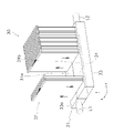
- FIG. 2 is a perspective view of a co-electrolysis/reformer.
- FIG. 3 is a cross-sectional view of a co-electrolysis/reformer.
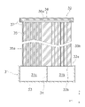
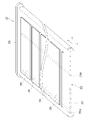
- FIG. 4 is a perspective view of a co-electrolytic/reforming cell.
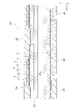
- FIG. 5 is a cross-sectional view of a co-electrolytic/reforming cell.
- FIG. 6 is a flowchart for explaining the methane production method.
- FIG. 1 is a block diagram showing the configuration of a methane production system 1 according to this embodiment.
- the methane production system 1 includes a CO 2 supply device 10 , an H 2 O supply device 20 , a co-electrolysis/reformer 30 , a storage/supply section 40 , a methane storage section 50 and a control section 60 .
- the CO 2 supply device 10 is connected to the co-electrolysis/reformer 30 via the first pipe L1.
- the CO 2 supply device 10 supplies CO 2 (carbon dioxide) to the co-electrolysis/reformer 30 .
- the CO2 feed rate from the CO2 feeder 10 to the co-electrolysis/reformer 30 is preferably constant. Thereby, C (solid carbon) and CO 2 are produced due to the disproportionation reaction of CO (carbon monoxide) produced in each co-electrolysis/reforming cell 32 of the co-electrolysis/reformer 30. It can be suppressed.
- each co-electrolytic/reformer cell 32 described below operates in reforming mode, the CO 2 supply device 10 does not supply CO 2 to the co-electrolytic/reformer 30 .
- the H 2 O supply device 20 is connected to the co-electrolysis/reformer 30 via the first pipe L1.
- the H 2 O supply device 20 supplies H 2 O (moisture) to the co-electrolytic/reformer 30 .
- the H 2 O supplied from the H 2 O supply device 20 to the co-electrolysis/reformer 30 is wholly or mostly gaseous (water vapor), but some may be liquid (water).
- the H 2 O supply device 20 does not supply H 2 O to the co-electrolytic/reformer 30 .
- the co-electrolytic/reforming device 30 has a manifold 31 and a plurality of co-electrolytic/reforming cells 32 .
- the manifold 31 has a configuration capable of distributing gas to each co-electrolysis/reformer cell 32 and recovering gas from each co-electrolysis/reformer.
- the manifold 31 has a gas supply chamber 31a and a gas recovery chamber 31b inside.
- the gas supply chamber 31a and the gas recovery chamber 31b are airtightly separated from each other.
- a first pipe L1 is connected to the gas supply chamber 31a.
- CO 2 and H 2 O are supplied to the gas supply chamber 31a from the first pipe L1.
- H 2 and CO are supplied to the gas supply chamber 31a from the first pipe L1.
- the gas recovery chamber 31b recovers the gas generated in each co-electrolytic/reforming cell 32.
- a second pipe L2 is connected to the gas recovery chamber 31b.
- H 2 and CO are discharged from the gas recovery chamber 31b to the second pipe L2.
- CH 4 and H 2 O are discharged from the gas recovery chamber 31b to the second pipe L2.
- a reforming catalyst may be arranged in the gas recovery chamber 31b.
- the reforming catalyst may be in the form of pellets.
- the reforming catalyst may be filled in the gas recovery chamber 31b.
- Ru/Al 2 O 3 , Ni/Al 2 O 3 or the like can be used.
- each co-electrolytic/reforming cell 32 is supported by the manifold 31 .
- the tip of each co-electrolytic/reforming cell 32 is a free end.
- the number of co-electrolytic/reforming cells 32 is not particularly limited, and may be one or more.
- Each co-electrolytic/reforming cell 32 operates in a co - electrolytic mode producing H 2 (hydrogen), CO and O 2 (oxygen) from CO 2 and H 2 O, and It operates either in reforming mode to produce CH 4 (methane).
- co-electrolysis means producing H 2 , CO and O 2 by electrolyzing CO 2 and H 2 O together.
- reforming means producing CH4 and H2O from H2 and CO.
- each co-electrolytic/reforming cell 32 operates at a high temperature (eg, 600°C to 850°C).
- the operating temperature of each co-electrolytic/reforming cell 32 in the co-electrolytic mode is preferably 700° C. or higher and 850° C. or lower. By setting the operating temperature to 700° C. or higher, the CO concentration can be increased in thermodynamic equilibrium. By setting the operating temperature to 850° C. or lower, the amount of oxide ions flowing through the interconnector can be suppressed.
- each co-electrolytic/reforming cell 32 operates at a lower temperature (eg, 200° C.-500° C.) than the operating temperature of the co-electrolytic mode.
- the operating temperature of each co-electrolytic/reforming cell 32 in the reforming mode is preferably 350° C. or higher and 400° C. or lower. By setting the operating temperature to 350° C. or higher, it is possible to suppress phase transformation of the constituent material of the support substrate 35 to carbonate. By setting the operating temperature to 400° C. or lower, it is possible to suppress reforming of the generated CH 4 to H 2 and CO again.
- the operating temperature of the co-electrolytic/reforming cell 32 means the temperature at the center of the co-electrolytic/reforming cell 32 in the longitudinal direction (x-axis direction).
- the operating temperature of each co-electrolytic/reforming cell 32 is controlled by the controller 60 .
- each co-electrolysis/reforming cell 32 is supplied with CO 2 and H 2 O from the gas supply chamber 31a.
- H 2 , CO and O 2 ⁇ oxygen ions
- CO 2 and O 2 ⁇ oxygen ions
- the generated H 2 and CO are recovered in the gas recovery chamber 31b and then discharged from the second pipe L2.
- each co-electrolytic/reforming cell 32 is supplied with H 2 and CO from the gas supply chamber 31a.
- CH 4 and H 2 O are produced from H 2 and CO at the first electrode 2 .
- the generated CH 4 and H 2 O are discharged from the second pipe L2 after being recovered in the gas recovery chamber 31b.
- the storage/supply unit 40 is connected to the co-electrolysis/reformer 30 .
- the storage/supply unit 40 is connected to the co-electrolysis/reformer 30 via the second pipe L2 and the third pipe L3.
- the storage/supply unit 40 is directly connected to the gas recovery chamber 31b of the co-electrolysis/reformer 30 via the second pipe L2, and the gas recovery chamber 31b of the co-electrolysis/reformer 30 is connected via the third pipe L3. It is directly connected to the supply chamber 31a.
- the storage/supply unit 40 stores H 2 and CO discharged from the gas recovery chamber 31b through the second pipe L2. Therefore, the H 2 and CO produced in the co-electrolysis/reformer 30 are stored in the storage/supply section 40 as they are without their compositions being changed.
- the storage/supply unit 40 supplies the stored H 2 and CO to the gas supply chamber 31a through the third pipe L3. Therefore, the H 2 and CO produced in the co-electrolyzer/reformer 30 are returned to the co-electrolyte/reformer 30 as they are without being altered in composition.
- reservoir/supply 40 does not receive gas discharged from co-electrolysis/reformer 30 .
- the methane reservoir 50 is connected to the co-electrolysis/reformer 30 .
- the methane reservoir 50 is connected to the co-electrolysis/reformer 30 via the second pipe L2.
- the methane reservoir 50 is directly connected to the gas recovery chamber 31b of the co-electrolysis/reformer 30 by the second pipe L2.
- the methane reservoir 50 stores CH 4 and H 2 O discharged from the gas recovery chamber 31b through the second pipe L2.
- the methane reservoir 50 does not receive gas discharged from the co-electrolytic/reformer 30 .
- the control unit 60 controls the operating temperature of each co-electrolytic/reforming cell 32 .
- the control unit 60 adjusts at least one of the current value, the amount of gas supplied to the first electrode 2, which will be described later, and the amount of gas supplied to the first electrode 2, so that each common electrolysis/reforming cell 32 operating temperature can be controlled.
- the control unit 60 makes the operating temperature of the co-electrolytic/reforming cells 32 in the reforming mode lower than the operating temperature of the co-electrolytic/reforming cells 32 in the co-electrolytic mode.
- the controller 60 drives the pump 60a arranged in the third pipe L3.
- the H 2 and CO stored in the storage/supply unit 40 are supplied to the gas supply chamber 31a of the co-electrolysis/reformer 30 via the third pipe L3.
- the controller 60 does not drive the pump 60a when each co-electrolytic/reforming cell 32 operates in the co-electrolytic mode.
- FIG. 2 is a perspective view of the co-electrolysis/reformer 30.
- FIG. 3 is a cross-sectional view of a co-electrolysis/reformer 30.
- FIG. 4 is a perspective view of the co-electrolytic/reforming cell 32. As shown in FIG. Some of the co-electrolytic/reforming cells 32 are omitted from FIG.
- the manifold 31 As shown in FIGS. 2 and 3, the manifold 31 has a manifold body portion 33 and a partition plate .
- the manifold body 33 is hollow.
- the partition plate 34 is arranged inside the manifold body portion 33 .
- the partition plate 34 airtightly separates the gas supply chamber 31a and the gas recovery chamber 31b.
- the manifold body portion 33 has a top plate portion 33a. As shown in FIG. 3, a plurality of through holes 33b are formed in the top plate portion 33a. The through-holes 33b are arranged at predetermined intervals in the longitudinal direction (z-axis direction) of the manifold body portion 33 . Each through-hole 33b extends in the width direction (y-axis direction) of the manifold body portion 33 . In this embodiment, each through-hole 33b is an elongated hole communicating with both the gas supply chamber 31a and the gas recovery chamber 31b. may be separated.
- each co-electrolytic/reforming cell 32 extends away from manifold 31 .
- a base end portion of each co-electrolytic/reforming cell 32 is fixed to a through hole 33b of a top plate portion 33a by a bonding material (not shown) or the like.
- the base end of each co-electrolytic/reforming cell 32 may be inserted inside the through-hole 33b or may protrude outside the through-hole 33b.
- Each co-electrolytic/reforming cell 32 is arranged so that the main surfaces face each other.
- Each co-electrolytic/reforming cell 32 is arranged at predetermined intervals along the longitudinal direction (z-axis direction) of the manifold 31 . That is, the co-electrolytic/reforming cells 32 are arranged along the longitudinal direction of the manifold 31 .
- Each co-electrolytic/reforming cell 32 is electrically connected in series or in a combination of series and parallel connection by a collector member (not shown).
- the common electrolysis/reforming cell 32 has a support substrate 35, a communication member 36, a coating layer 37 and a plurality of element portions 38.
- the co-electrolysis/reforming cell 32 according to the present embodiment is a so-called horizontal-striped solid oxide electrolysis cell (SOEC).
- the support substrate 35 is plate-shaped.
- the vertical direction (x-axis direction) in FIG. 3 is the longitudinal direction of the support substrate 35, and the horizontal direction (y-axis direction) in FIG.
- first gas flow paths 35a and a plurality of second gas flow paths 35b are formed inside the support substrate 35.
- Each of the first gas flow paths 35 a and the second gas flow paths 35 b extends through the support substrate 35 from the proximal end of the co-electrolytic/reforming cell 32 toward the distal end thereof.
- Each first gas flow path 35 a and each second gas flow path 35 b penetrate through the support substrate 35 .
- the respective first gas flow paths 35a are arranged at intervals in the width direction of the support substrate 35 .
- Each of the second gas flow paths 35b is spaced apart from each other in the width direction of the support substrate 35 .
- the inner diameter of each first gas flow path 35a is larger than the inner diameter of each second gas flow path 35b, but the inner diameters of each first gas flow path 35a and each second gas flow path 35b are not particularly limited. .
- Each first gas flow path 35a opens to the gas supply chamber 31a. Gas flows into each first gas flow path 35a from the gas supply chamber 31a.
- Each second gas flow path 35b opens to the gas recovery chamber 31b. Gas flows out to the gas recovery chamber 31b from each of the second gas flow paths 35b.
- the support substrate 35 is made of a porous material that does not have electronic conductivity so as to prevent short circuits between the element portions 38 and permeate the gas.
- the support substrate 35 is made of, for example, CSZ (calcia stabilized zirconia), 8YSZ (yttria stabilized zirconia), Y 2 O 3 (yttria), MgO (magnesium oxide), MgAl 2 O 4 (magnesia alumina spinel), or a combination thereof. It can be composed of objects and the like.
- the porosity of the support substrate 35 can be 20-60%. In addition, the porosity described in this specification is a value measured by the Archimedes method.
- the communication member 36 is attached to the tip of the support substrate 35 .
- the communication member 36 can be made of the same porous material as the support substrate 35, for example.
- the communication member 36 has a communication channel 36a therein.
- the communication channel 36a communicates with each first gas channel 35a and each second gas channel 35b.
- the covering layer 37 covers the outer surfaces of the support substrate 35 and the communicating member 36 .
- the covering layer 37 is denser than the supporting substrate 35 and the communicating member 36 .
- the porosity of the coating layer 37 can be about 0 to 7%.
- the coating layer 37 can be made of a material used for the electrolyte 3 to be described later, crystallized glass, or the like.
- Each element section 38 is supported by the support substrate 35 .
- the element part 38 may be arranged on both main surfaces of the support substrate 35, or may be arranged on only one of the main surfaces.
- FIG. 5 is a cross-sectional view of the co-electrolytic/reforming cell 32 cut along the first gas flow path 35a.
- Each element section 38 has a first electrode 2 , an electrolyte 3 , a second electrode 4 , a reaction prevention film 5 and an interconnector 6 .
- the first electrode 2 converts CO 2 and H 2 O to H 2 , CO and O 2 according to the co-electrolytic chemical reaction shown in formula (1) below. - is generated.
- First electrode 2 (co-electrolysis mode): CO 2 +H 2 O + 4e ⁇ ⁇ CO + H 2 +2O 2- (1)
- the first electrode 2 When the co-electrolytic/reforming cell 32 operates in the reforming mode, the first electrode 2 produces CH 4 and H 2 O from H 2 and CO according to the co-electrolytic chemical reaction shown in Equation (2) below. .
- the first electrode 2 has a first electrode substrate 21 and a first electrode active portion 22 .
- the first electrode substrate 21 is arranged on the support substrate 35 .
- the first electrode substrate 21 is embedded in a recess formed on the surface of the support substrate 35, but may be placed on the surface of the support substrate 35.
- the thickness of the first electrode substrate 21 can be 50-500 ⁇ m.
- the first electrode substrate 21 is made of an electronically conductive porous material.
- the first electrode substrate 21 preferably has higher electron conductivity than the first electrode active portion 22 .
- the first electrode substrate 21 may or may not have oxygen ion conductivity.
- the first electrode substrate 21 can be composed of, for example, a composite of NiO and 8YSZ , a composite of NiO and Y2O3, a composite of NiO and CSZ, or the like.
- the first electrode active portion 22 is arranged on the first electrode substrate 21 .
- the thickness of the first electrode active portion 22 can be 5 to 100 ⁇ m.
- the first electrode active portion 22 has oxygen ion conductivity and electron conductivity.
- the first electrode active portion 22 preferably has oxygen ion conductivity higher than that of the first electrode substrate 21 .
- the first electrode active portion 22 can be composed of, for example, a composite of NiO and 8YSZ, a composite of NiO and GDC(Ce,Gd) O2 , gadolinium-doped ceria), or the like.
- An electrolyte 3 is arranged between the first electrode 2 and the second electrode 4 .
- the electrolyte 3 transfers O 2 ⁇ produced at the first electrode 2 to the second electrode 4 .
- An electrolyte 3 is arranged on the first electrode 2 .
- the electrolyte 3 extends longitudinally of the support substrate 35 between the two interconnectors 6 .
- the thickness of the electrolyte 3 can be, for example, 3-50 ⁇ m.
- the electrolyte 3 is composed of a dense material that has oxygen ion conductivity and no electronic conductivity.
- the electrolyte 3 is denser than the support substrate 35 .
- the porosity of the electrolyte 3 can be, for example, 0-7%.
- the electrolyte 3 can be composed of, for example, 8YSZ, LSGM (lanthanum gallate), or the like.
- the second electrode 4 is converted from O 2 ⁇ transferred from the first electrode 2 through the electrolyte 3 according to the chemical reaction shown in equation (3) below. Produces O2 . ⁇ Second electrode 4 (co-electrolytic mode): 2O 2 ⁇ ⁇ O 2 +4e ⁇ (3)
- the second electrode 4 does not function.
- the second electrode 4 has a second electrode active portion 41 and a second electrode base 42 .
- the second electrode active portion 41 is arranged on the reaction prevention film 5 .
- the thickness of the second electrode active portion 41 can be, for example, 10 to 100 ⁇ m.
- the second electrode active portion 41 is made of a porous material having oxygen ion conductivity and electron conductivity.
- the second electrode active portion 41 preferably has oxygen ion conductivity higher than that of the second electrode substrate 42 .
- the second electrode substrate 42 is arranged on the second electrode active portion 41 .
- the second electrode substrate 42 is electrically connected to the first electrode substrate 21 of the adjacent element section 38 via the interconnector 6 .
- the thickness of the second electrode substrate 42 can be, for example, 50-500 ⁇ m.
- the second electrode substrate 42 is composed of a porous material having electronic conductivity.
- the second electrode substrate 42 preferably has higher electron conductivity than the second electrode active portion 41 .
- the second electrode substrate 42 may or may not have oxygen ion conductivity.
- the second electrode substrate 42 can be made of, for example, LSCF, LSC, Ag (silver), Ag--Pd (silver-palladium alloy), or the like.
- the anti-reaction film 5 is arranged between the electrolyte 3 and the second electrode active portion 41 .
- the reaction-preventing film 5 prevents the substances contained in the electrolyte 3 and the second electrode active portion 41 from reacting to form a reaction layer with high electrical resistance.
- the thickness of the reaction prevention film 5 can be, for example, 3 to 50 ⁇ m.
- the reaction prevention film 5 is made of a dense material.
- the anti-reaction film 5 can be composed of GDC, for example.
- the interconnector 6 is connected to the second electrode substrate 42 and also to the first electrode substrate 21 of the adjacent element section 38 .
- the thickness of the interconnector 6 can be, for example, 10-100 ⁇ m.
- the interconnector 6 is made of a dense material having electronic conductivity.
- the interconnector 6 is denser than the support substrate 35 .
- the interconnector 6 can have a porosity of 0 to 7%.
- the interconnector 6 can be made of, for example, LaCrO 3 (lanthanum chromite), (Sr, La)TiO 3 (strontium titanate), or the like.
- FIG. 6 is a flow diagram for explaining a methane production method using the co-electrolytic/reforming cell 32. As shown in FIG.
- step S1 the co-electrolysis/reforming cell 32 co-electrolyzes CO 2 and H 2 O to generate H 2 and CO at the first electrode 2 (co-electrolysis step).
- step S2 the storage/supply unit 40 stores H 2 and CO produced in the co-electrolytic/reforming cell 32 (first storage step).
- step S3 the storage/supply unit 40 supplies the stored H 2 and CO to the co-electrolytic/reforming cell 32 (supply step).
- step S4 the co - electrolytic/reforming cell 32 reforms H2 and CO to produce CH4 ( reforming step).
- step S5 the methane storage unit 50 stores the CH4 produced in the co-electrolysis/reforming cell 32 ( second storage step).
- the methane production system 1 includes a co-electrolytic/reforming cell 32 and a controller 60 that controls the operating temperature of the co-electrolytic/reforming cell 32 .
- the co-electrolysis/reforming cell 32 operates in a co-electrolysis mode that produces H 2 and CO from CO 2 and H 2 O at the first electrode 2 and CH 4 from the H 2 and CO produced in the co-electrolysis mode. It operates either in reforming mode, which is produced at electrode 2 .
- the control unit 60 makes the operating temperature of the co-electrolytic/reforming cell 32 in the reforming mode lower than the operating temperature of the co-electrolytic/reforming cell 32 in the co-electrolytic mode.
- the H 2 and CO produced in the co-electrolysis/reformation cell 32 can be used to produce CH 4 on-site in the co-electrolysis/reformation cell 32 . Therefore, there is no need to transport H2 and CO from the plant in which the co - electrolyzer is installed to the plant in which the reformer is installed.
- the co-electrolysis/reforming cell 32 is a horizontally-striped SOEC, but it is not limited to this.
- the co-electrolytic/reforming cell 32 may be a vertically striped (hollow flat plate), flat plate, cylindrical, etc. SOEC.
- the configuration of the vertically-striped SOEC is described, for example, in Japanese Patent Application Laid-Open No. 2015-125897.
- the configuration of a flat SOEC is described in, for example, Japanese Patent Application Laid-Open No. 2020-177839.
- the configuration of a cylindrical SOEC is described, for example, in JP-A-2008-270203.
- horizontal-striped SOECs are particularly preferred because they have a higher utilization efficiency of H 2 O than other SOFCs.
- the element section 38 has the first electrode 2, the electrolyte 3, the second electrode 4, the reaction prevention film 5 and the interconnector 6, but at least the first electrode 2, the electrolyte 3 and the second electrode 4 is sufficient.
- the control unit 60 drives the pump 60a arranged in the third pipe L3 to cause the storage/supply unit 40 to
- H 2 and CO are supplied to the electrolysis/reformer 30
- the present invention is not limited to this.
- the control unit 60 stores/supplies H 2 and CO may be supplied to co-electrolytic/reformer 30 from supply 40 .
- Methane Production System 10 CO 2 Supply Device 20 H 2 O Supply Device 30 Co-Electrolysis/Reformer 31 Manifold 32 Co-Electrolysis/Reformer Cell 38 Element Part 2 First Electrode 3 Electrolyte 4 Second Electrode 40 Storage/Supply Part 50 Methane reservoir 60 Controller L1 First pipe L2 Second pipe L3 Third pipe
Abstract
Description
図1は、本実施形態に係るメタン製造システム1の構成を示すブロック図である。 (Methane production system)
FIG. 1 is a block diagram showing the configuration of a
図2は、共電解/改質装置30の斜視図である。図3は、共電解/改質装置30の断面図である。図4は、共電解/改質セル32の斜視図である。図2では、一部の共電解/改質セル32が省略されている。 (Configuration of co-electrolysis/reformer 30)
FIG. 2 is a perspective view of the co-electrolysis/
図2及び図3に示すように、マニホールド31は、マニホールド本体部33及び仕切板34を有する。 [Manifold 31]
As shown in FIGS. 2 and 3, the manifold 31 has a
図2及び図3に示すように、各共電解/改質セル32は、マニホールド31から離れる方向に延びる。各共電解/改質セル32の基端部は、接合材(不図示)などによって天板部33aの貫通孔33bに固定される。各共電解/改質セル32の基端部は、貫通孔33bの内側に挿入されてもよいし、貫通孔33bの外側に出ていてもよい。 [Co-electrolytic/reforming cell 32]
As shown in FIGS. 2 and 3, each co-electrolytic/reforming
図5は、第1ガス流路35aに沿って切断した共電解/改質セル32の断面図である。 [Element part 38]
FIG. 5 is a cross-sectional view of the co-electrolytic/reforming
・第1電極2(共電解モード):CO2+H2O+4e-→CO+H2+2O2-・・・(1) When the co-electrolytic/reforming
・First electrode 2 (co-electrolysis mode): CO 2 +H 2 O + 4e − →CO + H 2 +2O 2- (1)
・第1電極2(改質モード):3H2+CO→CH4+H2O・・・(2) When the co-electrolytic/reforming
・First electrode 2 (reforming mode): 3H 2 +CO→CH 4 +H 2 O (2)
・第2電極4(共電解モード):2O2-→O2+4e-・・・(3) When the co-electrolytic/reforming
・Second electrode 4 (co-electrolytic mode): 2O 2− → O 2 +4e − (3)
図6は、共電解/改質セル32を用いたメタン製造方法を説明するためのフロー図である。 (Methane production method)
FIG. 6 is a flow diagram for explaining a methane production method using the co-electrolytic/reforming
メタン製造システム1は、共電解/改質セル32と、共電解/改質セル32の作動温度を制御する制御部60とを備える。共電解/改質セル32は、CO2及びH2OからH2及びCOを第1電極2において生成する共電解モードと、共電解モードで生成されたH2及びCOからCH4を第1電極2において生成する改質モードとのいずれかで作動する。制御部60は、改質モードにおける共電解/改質セル32の作動温度を、共電解モードにおける共電解/改質セル32の作動温度より低くする。 (feature)
The
以上、本発明の実施形態について説明したが、本発明はこれらに限定されるものではなく、本発明の趣旨を逸脱しない限りにおいて種々の変更が可能である。 (Modification of embodiment)
Although the embodiments of the present invention have been described above, the present invention is not limited to these, and various modifications are possible without departing from the gist of the present invention.
上記実施形態において、共電解/改質セル32は、横縞型のSOECであることとしたが、これに限られない。共電解/改質セル32は、縦縞型(中空平板型)、平板型、円筒型などのSOECであってもよい。縦縞型のSOECの構成は、例えば特開特開2015-125897号公報に記載されている。平板型のSOECの構成は、例えば特開2020-177839号公報に記載されている。円筒型SOECの構成は、例えば特開特開2008-270203号公報に記載されている。ただし、横縞型のSOECは、他のSOFCに比べてH2Oの利用効率が高いため特に好ましい。 [Modification 1]
In the above-described embodiment, the co-electrolysis/reforming
上記実施形態において、素子部38は、第1電極2、電解質3、第2電極4、反応防止膜5及びインターコネクタ6を有することとしたが、少なくとも第1電極2、電解質3及び第2電極4を有していればよい。 [Modification 2]
In the above embodiment, the
上記実施形態において、制御部60は、各共電解/改質セル32が改質モードで作動する場合、第3配管L3に配置されたポンプ60aを駆動させることによって、貯留/供給部40から共電解/改質装置30にH2及びCOを供給することとしたが、これに限られない。例えば、貯留/供給部40に貯留されたH2及びCOが加圧されている場合、制御部60は、ポンプ60aに代えて設けられた流量調整弁の開度を調整することによって、貯留/供給部40から共電解/改質装置30にH2及びCOを供給してもよい。 [Modification 3]
In the above-described embodiment, when each common electrolysis/reforming
10 CO2供給装置
20 H2O供給装置
30 共電解/改質装置
31 マニホールド
32 共電解/改質セル
38 素子部
2 第1電極
3 電解質
4 第2電極
40 貯留/供給部
50 メタン貯留部
60 制御部
L1 第1配管
L2 第2配管
L3 第3配管 1
Claims (6)
- 第1電極と、第2電極と、前記第1電極及び第2電極の間に配置される電解質とを有する共電解/改質セルと、
前記共電解/改質セルの作動温度を制御する制御部と、
を備え、
前記共電解/改質セルは、CO2及びH2OからH2及びCOを前記第1電極において生成する共電解モードと、前記共電解モードで生成されたH2及びCOからCH4を前記第1電極において生成する改質モードとのいずれかで作動し、
前記制御部は、前記改質モードにおける前記共電解/改質セルの作動温度を、前記共電解モードにおける前記共電解/改質セルの作動温度より低くする、
メタン製造システム。 a co-electrolytic/reforming cell having a first electrode, a second electrode, and an electrolyte disposed between the first and second electrodes;
a controller for controlling the operating temperature of the co-electrolytic/reforming cell;
with
The co-electrolysis/reforming cell is configured in a co - electrolysis mode to produce H2 and CO from CO2 and H2O at the first electrode, and to convert H2 and CO produced in the co - electrolysis mode to CH4. operating in either the reforming mode produced at the first electrode,
The control unit makes the operating temperature of the co-electrolysis/reforming cell in the reforming mode lower than the operating temperature of the co-electrolysis/reforming cell in the co-electrolysis mode.
Methane production system. - 前記共電解モードにおける前記共電解/改質セルの作動温度は、700℃以上850℃以下であり、
前記改質モードにおける前記共電解/改質セルの作動温度は、350℃以上400℃以下である、
請求項1に記載のメタン製造システム。 The operating temperature of the co-electrolysis/reforming cell in the co-electrolysis mode is 700° C. or higher and 850° C. or lower,
The operating temperature of the co-electrolytic/reforming cell in the reforming mode is 350° C. or higher and 400° C. or lower.
The methane production system according to claim 1. - 前記共電解/改質セルが前記共電解モードで作動する場合、前記第1電極において生成されたH2及びCOを貯留し、前記共電解/改質セルが前記改質モードで作動する場合、貯留されたH2及びCOを前記第1電極に供給する貯留/供給部を備える、
請求項1又は2に記載のメタン製造システム。 when the co-electrolysis/reformation cell operates in the co-electrolysis mode, storing H2 and CO produced at the first electrode; and when the co-electrolysis/reformation cell operates in the reforming mode, a storage/supply unit that supplies stored H2 and CO to the first electrode;
The methane production system according to claim 1 or 2. - 第1電極と、第2電極と、前記第1電極及び第2電極の間に配置される電解質とを有する共電解/改質セルを用いたメタン製造方法であって、
CO2及びH2OからH2及びCOを前記第1電極において生成する共電解工程と、
前記共電解工程で生成されたH2及びCOからCH4を前記第1電極において生成する改質工程と、
を備えるメタン製造方法。 A method for producing methane using a co-electrolytic/reforming cell having a first electrode, a second electrode, and an electrolyte disposed between the first and second electrodes, comprising:
a co-electrolytic step of producing H2 and CO from CO2 and H2O at the first electrode;
a reforming step of producing CH4 at the first electrode from H2 and CO produced in the co - electrolytic step;
A methane production method comprising: - 前記共電解工程で生成されたH2及びCOを貯留する第1貯留工程をさらに備え、
前記改質工程では、前記貯留工程で貯留されたH2及びCOからCH4を生成する、
請求項4に記載のメタン製造方法。 Further comprising a first storage step of storing H 2 and CO generated in the co-electrolysis step,
In the reforming step, CH4 is generated from H2 and CO stored in the storage step.
The method for producing methane according to claim 4. - 前記改質工程で生成されたCH4を貯留する第2貯留工程をさらに備える、
請求項5に記載のメタン製造方法。 Further comprising a second storage step of storing CH4 generated in the reforming step,
The method for producing methane according to claim 5.
Priority Applications (5)
| Application Number | Priority Date | Filing Date | Title |
|---|---|---|---|
| CN202280011553.XA CN116867757A (en) | 2021-03-11 | 2022-03-04 | Methane production system and methane production method |
| EP22767026.2A EP4306502A1 (en) | 2021-03-11 | 2022-03-04 | Methane production system and methane production method |
| AU2022234935A AU2022234935B2 (en) | 2021-03-11 | 2022-03-04 | Methane production system and methane production method |
| JP2023505504A JPWO2022191069A1 (en) | 2021-03-11 | 2022-03-04 | |
| US18/354,123 US20230357935A1 (en) | 2021-03-11 | 2023-07-18 | Methane production system and methane production method |
Applications Claiming Priority (2)
| Application Number | Priority Date | Filing Date | Title |
|---|---|---|---|
| JP2021039697 | 2021-03-11 | ||
| JP2021-039697 | 2021-03-11 |
Related Child Applications (1)
| Application Number | Title | Priority Date | Filing Date |
|---|---|---|---|
| US18/354,123 Continuation US20230357935A1 (en) | 2021-03-11 | 2023-07-18 | Methane production system and methane production method |
Publications (1)
| Publication Number | Publication Date |
|---|---|
| WO2022191069A1 true WO2022191069A1 (en) | 2022-09-15 |
Family
ID=83227865
Family Applications (1)
| Application Number | Title | Priority Date | Filing Date |
|---|---|---|---|
| PCT/JP2022/009406 WO2022191069A1 (en) | 2021-03-11 | 2022-03-04 | Methane production system and methane production method |
Country Status (6)
| Country | Link |
|---|---|
| US (1) | US20230357935A1 (en) |
| EP (1) | EP4306502A1 (en) |
| JP (1) | JPWO2022191069A1 (en) |
| CN (1) | CN116867757A (en) |
| AU (1) | AU2022234935B2 (en) |
| WO (1) | WO2022191069A1 (en) |
Citations (7)
| Publication number | Priority date | Publication date | Assignee | Title |
|---|---|---|---|---|
| JP2008270203A (en) | 2007-03-28 | 2008-11-06 | Mitsubishi Heavy Ind Ltd | Solid oxide fuel cell and water electrolysis cell |
| JP2015125897A (en) | 2013-12-26 | 2015-07-06 | 京セラ株式会社 | Electrolysis cell, electrolysis cell stack device, electrolysis module, and electrolytic device |
| JP2018154864A (en) | 2017-03-16 | 2018-10-04 | 東芝エネルギーシステムズ株式会社 | High temperature steam electrolysis cell, hydrogen electrode layer therefor, and solid oxide electrochemical cell |
| JP2019112717A (en) * | 2017-12-22 | 2019-07-11 | コミッサリア ア レネルジー アトミーク エ オ ゼネルジ ザルタナテイヴ | Method of startup mode or standby mode operation of power-to-gas unit including multiple high temperature electrolysis (soec) or co-electrolysis reactors |
| JP2019175636A (en) | 2018-03-28 | 2019-10-10 | 株式会社豊田中央研究所 | Boiling cooling type valve, boiling cooling type CO2 separator, SOFC system, SOEC system, and R-SOC system |
| WO2020071376A1 (en) * | 2018-10-01 | 2020-04-09 | 国立研究開発法人産業技術総合研究所 | Electrochemical catalyst, assembly, electrochemical reactor, hydrocarbon generation system and method for generating hydrocarbon |
| JP2020177839A (en) | 2019-04-19 | 2020-10-29 | 森村Sofcテクノロジー株式会社 | Electrochemical reaction cell stack |
-
2022
- 2022-03-04 CN CN202280011553.XA patent/CN116867757A/en active Pending
- 2022-03-04 JP JP2023505504A patent/JPWO2022191069A1/ja active Pending
- 2022-03-04 AU AU2022234935A patent/AU2022234935B2/en active Active
- 2022-03-04 EP EP22767026.2A patent/EP4306502A1/en active Pending
- 2022-03-04 WO PCT/JP2022/009406 patent/WO2022191069A1/en active Application Filing
-
2023
- 2023-07-18 US US18/354,123 patent/US20230357935A1/en active Pending
Patent Citations (7)
| Publication number | Priority date | Publication date | Assignee | Title |
|---|---|---|---|---|
| JP2008270203A (en) | 2007-03-28 | 2008-11-06 | Mitsubishi Heavy Ind Ltd | Solid oxide fuel cell and water electrolysis cell |
| JP2015125897A (en) | 2013-12-26 | 2015-07-06 | 京セラ株式会社 | Electrolysis cell, electrolysis cell stack device, electrolysis module, and electrolytic device |
| JP2018154864A (en) | 2017-03-16 | 2018-10-04 | 東芝エネルギーシステムズ株式会社 | High temperature steam electrolysis cell, hydrogen electrode layer therefor, and solid oxide electrochemical cell |
| JP2019112717A (en) * | 2017-12-22 | 2019-07-11 | コミッサリア ア レネルジー アトミーク エ オ ゼネルジ ザルタナテイヴ | Method of startup mode or standby mode operation of power-to-gas unit including multiple high temperature electrolysis (soec) or co-electrolysis reactors |
| JP2019175636A (en) | 2018-03-28 | 2019-10-10 | 株式会社豊田中央研究所 | Boiling cooling type valve, boiling cooling type CO2 separator, SOFC system, SOEC system, and R-SOC system |
| WO2020071376A1 (en) * | 2018-10-01 | 2020-04-09 | 国立研究開発法人産業技術総合研究所 | Electrochemical catalyst, assembly, electrochemical reactor, hydrocarbon generation system and method for generating hydrocarbon |
| JP2020177839A (en) | 2019-04-19 | 2020-10-29 | 森村Sofcテクノロジー株式会社 | Electrochemical reaction cell stack |
Non-Patent Citations (1)
| Title |
|---|
| LONG CHEN, FANGLIN CHEN, CHANGRONG XIA: "Direct synthesis of methane from CO 2 –H 2 O co-electrolysis in tubular solid oxide electrolysis cells", ENERGY & ENVIRONMENTAL SCIENCE, RSC PUBL., CAMBRIDGE, vol. 7, no. 12, 1 January 2014 (2014-01-01), Cambridge , pages 4018 - 4022, XP055405403, ISSN: 1754-5692, DOI: 10.1039/C4EE02786H * |
Also Published As
| Publication number | Publication date |
|---|---|
| AU2022234935B2 (en) | 2024-03-28 |
| EP4306502A1 (en) | 2024-01-17 |
| CN116867757A (en) | 2023-10-10 |
| AU2022234935A1 (en) | 2023-08-03 |
| US20230357935A1 (en) | 2023-11-09 |
| JPWO2022191069A1 (en) | 2022-09-15 |
Similar Documents
| Publication | Publication Date | Title |
|---|---|---|
| EP3026745B1 (en) | Hybrid device and hybrid system | |
| JP2006332027A (en) | Reformer-integrated fuel cell | |
| EP3780201A1 (en) | Fuel battery single cell unit, fuel battery module, and fuel battery device | |
| KR20150070124A (en) | Fuel battery and operation method thereof | |
| EP3780198A1 (en) | Metal-supported fuel cell, and fuel cell module | |
| US20120058406A1 (en) | Solid oxide fuel cell | |
| JP6605084B1 (en) | Cell stack device | |
| JP5138179B2 (en) | Solid oxide fuel cell with excellent carbon deposition resistance | |
| WO2022191069A1 (en) | Methane production system and methane production method | |
| CN109563634A (en) | Hydrogen processing unit | |
| WO2022191061A1 (en) | Methane production system | |
| JP6594496B1 (en) | Fuel cell system | |
| JP6734455B1 (en) | Fuel cell unit and fuel cell system | |
| US11749821B2 (en) | Fuel cell device and method for operating fuel cell device | |
| TWI804207B (en) | Fuel gas supply device for fuel cell | |
| JP7236588B1 (en) | Electrolytic cell and cell stack device | |
| US20220029195A1 (en) | Electrochemical cell | |
| JP2023072892A (en) | Electrolysis cell system | |
| WO2023286749A1 (en) | Electrochemical cell, electrochemical cell device, module, and module storage device | |
| US20220045348A1 (en) | Electrochemical cell and hydrogen generation method | |
| JP2023072926A (en) | Electrolysis cell and cell stack device | |
| JP2018037162A (en) | Fuel battery stack, and fuel battery cell | |
| JP2023072891A (en) | Electrolysis cell, and cell stack device | |
| JP6121826B2 (en) | Electrolyzer | |
| JP2022181806A (en) | Electrolysis cell |
Legal Events
| Date | Code | Title | Description |
|---|---|---|---|
| 121 | Ep: the epo has been informed by wipo that ep was designated in this application |
Ref document number: 22767026 Country of ref document: EP Kind code of ref document: A1 |
|
| ENP | Entry into the national phase |
Ref document number: 2023505504 Country of ref document: JP Kind code of ref document: A |
|
| WWE | Wipo information: entry into national phase |
Ref document number: 202280011553.X Country of ref document: CN |
|
| ENP | Entry into the national phase |
Ref document number: 2022234935 Country of ref document: AU Date of ref document: 20220304 Kind code of ref document: A |
|
| WWE | Wipo information: entry into national phase |
Ref document number: 2022767026 Country of ref document: EP |
|
| NENP | Non-entry into the national phase |
Ref country code: DE |
|
| ENP | Entry into the national phase |
Ref document number: 2022767026 Country of ref document: EP Effective date: 20231011 |