WO2022190196A1 - 変化検知装置および変化検知方法 - Google Patents
変化検知装置および変化検知方法 Download PDFInfo
- Publication number
- WO2022190196A1 WO2022190196A1 PCT/JP2021/009209 JP2021009209W WO2022190196A1 WO 2022190196 A1 WO2022190196 A1 WO 2022190196A1 JP 2021009209 W JP2021009209 W JP 2021009209W WO 2022190196 A1 WO2022190196 A1 WO 2022190196A1
- Authority
- WO
- WIPO (PCT)
- Prior art keywords
- change detection
- coherence
- sar
- phase
- image
- Prior art date
- Legal status (The legal status is an assumption and is not a legal conclusion. Google has not performed a legal analysis and makes no representation as to the accuracy of the status listed.)
- Ceased
Links
Images






Classifications
-
- G—PHYSICS
- G01—MEASURING; TESTING
- G01S—RADIO DIRECTION-FINDING; RADIO NAVIGATION; DETERMINING DISTANCE OR VELOCITY BY USE OF RADIO WAVES; LOCATING OR PRESENCE-DETECTING BY USE OF THE REFLECTION OR RERADIATION OF RADIO WAVES; ANALOGOUS ARRANGEMENTS USING OTHER WAVES
- G01S13/00—Systems using the reflection or reradiation of radio waves, e.g. radar systems; Analogous systems using reflection or reradiation of waves whose nature or wavelength is irrelevant or unspecified
- G01S13/88—Radar or analogous systems specially adapted for specific applications
- G01S13/89—Radar or analogous systems specially adapted for specific applications for mapping or imaging
- G01S13/90—Radar or analogous systems specially adapted for specific applications for mapping or imaging using synthetic aperture techniques, e.g. synthetic aperture radar [SAR] techniques
- G01S13/9021—SAR image post-processing techniques
-
- G—PHYSICS
- G01—MEASURING; TESTING
- G01S—RADIO DIRECTION-FINDING; RADIO NAVIGATION; DETERMINING DISTANCE OR VELOCITY BY USE OF RADIO WAVES; LOCATING OR PRESENCE-DETECTING BY USE OF THE REFLECTION OR RERADIATION OF RADIO WAVES; ANALOGOUS ARRANGEMENTS USING OTHER WAVES
- G01S13/00—Systems using the reflection or reradiation of radio waves, e.g. radar systems; Analogous systems using reflection or reradiation of waves whose nature or wavelength is irrelevant or unspecified
- G01S13/88—Radar or analogous systems specially adapted for specific applications
- G01S13/89—Radar or analogous systems specially adapted for specific applications for mapping or imaging
- G01S13/90—Radar or analogous systems specially adapted for specific applications for mapping or imaging using synthetic aperture techniques, e.g. synthetic aperture radar [SAR] techniques
- G01S13/9021—SAR image post-processing techniques
- G01S13/9023—SAR image post-processing techniques combined with interferometric techniques
Definitions
- the present invention relates to a change detection device and a change detection method that perform change detection based on SAR images.
- Synthetic Aperture Radar (SAR) technology transmits and receives electromagnetic waves to and from satellites, aircraft, and other flying objects while they are moving. It is a technique for obtaining an image (hereinafter referred to as a SAR image). Synthetic aperture radar is used, for example, for signal processing of reflected waves from the ground surface to analyze ground surface displacement.
- An image taken by a flying object such as an artificial satellite is called an observation image.
- the observed image corresponds to the SAR image.
- a flying object that transmits and receives electromagnetic waves is an artificial satellite, but the flying object is not limited to an artificial satellite.
- Patent Literature 1 describes a change detection technique using coherence (Coherent Change Detection).
- Coherence is calculated by complex correlation of pixels corresponding to the same position in a plurality of SAR images in K (K ⁇ 2) SAR images.
- the pair of SAR images be (p,q) and the components of the coherence matrix be c p,q .
- Each of p and q is a value equal to or less than K and indicates one of K SAR images.
- the phase ⁇ p,q (specifically, the phase difference) is calculated for the pair of SAR images.
- the absolute value of the value obtained by averaging exp(-j ⁇ p,q ) for a plurality of pixels in a predetermined region including the pixel for coherence calculation becomes the component c p,q of the coherence matrix.
- a p ⁇ A q ⁇ exp( ⁇ j ⁇ p,q ) may be averaged, where A p is the intensity in the SAR image p and A q is the intensity in the SAR image q.
- the value represented by the components of the coherence matrix be the coherence value. Also, assume a coherence image having coherence values as pixel values.
- a change detection device that uses change detection technology that uses coherence performs change detection based on coherence images.
- the change detection device determines that a change has occurred when detecting a region with a low coherence value in the coherence image. For example, the change detection device generates a coherence image from an already acquired SAR image and a new SAR image targeting the same observation area as the SAR image was acquired. It should be noted that, as an example, a change occurs in the region due to the appearance of a new structure or the disappearance of an existing structure.
- SAR images that have already been acquired may be referred to as accumulated SAR images.
- the newly acquired SAR image may be referred to as a comparison target SAR image.
- a plurality of SAR images may be referred to as an SAR image group.
- the group of previously acquired SAR images consists of a plurality of previously acquired SAR images.
- SAR images may be affected by layover. For example, in urban areas where there are buildings in the observation area, reflected waves from tall buildings, low buildings, and the ground surface are mixed in radars mounted on satellites. . As a result, the waveform of the received wave of the radar mounted on the satellite becomes unstable. Specifically, in the SAR image, layover may occur in which information about tall buildings overlaps information about low buildings. In situations where layover occurs, changes can occur between SAR images, even though there is actually no change in the observation area.
- Patent Document 2 For the purpose of reducing the influence of layover on SAR images, there is a technique that uses the three-dimensional structure of an observation area estimated from SAR images (see, for example, Patent Document 2).
- the device described in Patent Document 2 inputs a plurality of SAR images.
- the device converts the distortion difference between multiple SAR images into height.
- the device generates three-dimensional shape data (three-dimensional information) of the observation area using height information.
- a change detection device to which the technology is applied is called an application device.
- the application device generates three-dimensional information for reducing the influence of layover from a plurality of SAR images before change (before change occurs in the observation area). Also, the applying apparatus generates three-dimensional information for reducing the effects of layover from the newly acquired SAR images. Then, the application device refers to both three-dimensional information to perform change detection.
- the application apparatus performs processing for generating three-dimensional information using a plurality of SAR images before change, and generates three-dimensional information using a plurality of SAR images newly acquired after change. Perform processing for generation. Therefore, many image acquisitions are required to reconstruct the three-dimensional structure before and after the change. Therefore, image acquisition takes a lot of time and effort.
- An object of the present invention is to provide a change detection device and a change detection method that can perform change detection in a state in which the influence of layover is reduced without reproducing the three-dimensional structure after change.
- a change detection apparatus includes three-dimensional structure reconstruction means for reconstructing a three-dimensional structure of a predetermined region in an observation region, and a predetermined three-dimensional structure in a plurality of SAR images in which the observation region is captured using the three-dimensional structure.
- a phase removing means for removing the phase signal of the region, and a change detecting means for generating a coherence image from the phase-removed SAR image pair and detecting a change in the observation region based on the coherence values of the pixels forming the coherence image.
- a change detection method reconstructs a three-dimensional structure of a predetermined region in an observation region, and removes a phase signal of the predetermined region in a plurality of SAR images in which the observation region is captured using the three-dimensional structure. , a coherence image is generated from the phase-removed SAR image pair, and changes in the observed region are detected based on the coherence values of the pixels forming the coherence image.
- a change detection program provides a computer with processing for reconstructing a three-dimensional structure of a predetermined region in an observation region, and reconstruction of a predetermined region in a plurality of SAR images in which the observation region is photographed using the three-dimensional structure.
- a process of removing the phase signal and a process of generating a coherence image from the phase-removed SAR image pair and detecting a change in the observation area based on the coherence values of the pixels forming the coherence image are executed.
- change detection can be performed in a state in which the influence of layover is reduced without reproducing the three-dimensional structure after change.
- FIG. 1 is a block diagram showing a configuration example of a change detection device according to a first embodiment
- FIG. 4 is a flow chart showing the operation of the change detection device of the first embodiment
- It is an explanatory view for explaining SAR tomography.
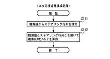
- 4 is a flowchart showing three-dimensional structure reconstruction processing in the first embodiment
- 4 is a flowchart showing phase signal removal processing
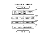
- 4 is a flowchart showing coherent change detection processing
- FIG. 11 is a block diagram showing a configuration example of a change detection device according to a second embodiment
- FIG. 9 is a flow chart showing the operation of the change detection device of the second embodiment
- 9 is a flowchart showing three-dimensional structure reconstruction processing in the second embodiment
- FIG. 11 is a block diagram showing a configuration example of a change detection device according to a third embodiment
- FIG. 10 is a flow chart showing the operation of the change detection device of the third embodiment
- FIG. 11 is a block diagram showing a modification of the change detection device of the third embodiment
- FIG. 10 is a flow chart showing the operation of a modification of the change detection device of the third embodiment
- FIG. 12 is a block diagram showing a configuration example of a change detection device according to a fourth embodiment
- FIG. 1 is a block diagram showing an example of a computer having a CPU
- FIG. 3 is a block diagram showing the main parts of the change detection device
- FIG. FIG. 11 is a block diagram showing the main parts of a change detection device according to another embodiment
- FIG. 11 is a block diagram showing the main parts of a change detection device according to still another embodiment;
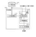
- FIG. 1 is a block diagram showing a configuration example of a change detection device according to the first embodiment.
- the change detection device 100 shown in FIG. 1 includes a three-dimensional structure reconstruction unit 110, a phase removal unit 120, and a coherent change detection unit .
- the three-dimensional structure reconstruction unit 110 reconstructs the three-dimensional structure of the observation area from a plurality of SAR images accumulated in the SAR image storage unit 700.
- the phase removing section 120 includes a phase signal estimating section 121 and a phase signal removing section 122 .
- the phase signal estimator 121 estimates the phase signal of a predetermined area in the observation area from the SAR image pair.
- the predetermined area is an area (layover area) where layover may occur.
- the phase remover 120 removes the phase signal in the layover region.
- the phase removal unit 120 removes phase signals caused by height (building height) that causes layover by referring to the three-dimensional structure of the observation area.
- the phase remover 120 simulates the mixture of signals in the layover region using three-dimensional point cloud data having information on reflection intensity and phase reproduced by SAR tomography. That is, the phase remover 120 reproduces the phase that is not related to changes in the ground surface (that is, the phase that is caused by the height of the building). Then, the phase removal section 120 removes such phase signals from the observed signal.
- phase signal caused by height varies greatly between multiple SAR images. Therefore, the removal of the phase signal due to height reduces the variation between SAR images when no variation actually occurs. As a result, more accurate coherent change detection can be performed even for layover regions.
- the coherence change detection unit 130 generates a coherence image from one SAR image among the SAR images accumulated in the SAR image storage unit 700 and the SAR image to be compared.
- Coherent change detection section 130 uses the coherence image to determine whether or not a change has occurred in the observation region.
- the SAR image to be compared may be a newly acquired SAR image or an SAR image selected from a plurality of SAR images accumulated in the SAR image storage unit 700 .
- the three-dimensional structure reconstruction unit 110 reads out existing SAR image groups from the SAR image storage unit 700 . Then, the three-dimensional structure reconstruction unit 110 reconstructs the three-dimensional structure of a predetermined area in the observation area using the SAR tomography technique (step S101).
- the phase signal estimation unit 121 reads one SAR image from the SAR image storage unit 700. Also, the phase signal estimation unit 121 inputs the SAR image to be compared. The phase signal estimation unit 121 uses the three-dimensional structure to estimate the phase signal of the layover region of the SAR image pair of the SAR image read from the SAR image storage unit 700 and the SAR image to be compared (step S102 ).
- the phase signal removing unit 122 removes the phase signal estimated by the phase signal estimating unit 121 of the SAR image pair (step S103).
- the coherence change detection unit 130 calculates the coherence value between the SAR images of the SAR image pair.
- the coherence change detection unit 130 generates a coherence image having the coherence values as pixel values.
- the coherent change detection unit 130 executes coherent change detection processing (step S104). That is, coherent change detection section 130 determines whether or not there is a portion where a change has occurred in the observation region.
- the 3D structure reconstruction unit 110 reconstructs the 3D structure of a predetermined region by 3D structure reconstruction processing using the SAR tomography technique.
- FIG. 3 is an explanatory diagram for explaining SAR tomography.
- the artificial satellite travels in a direction perpendicular to the paper surface. That is, the azimuth direction is the direction perpendicular to the plane of the paper.
- r indicates the range direction.
- s indicates the elevation direction.
- N corresponds to the number of SAR images accumulated in the SAR image storage unit 700 .
- the observed value g at the azimuth-range position, the complex reflection distribution ⁇ , and the steering matrix R have a relationship represented by the following equation (1).
- the three-dimensional structure reconstruction unit 110 can estimate (calculate) the complex reflection distribution ⁇ at each position in the elevation direction from the observed value g and the steering matrix R.
- the complex reflection distribution ⁇ contains intensity information and phase information. Therefore, the three-dimensional structure reconstruction unit 110 can obtain three-dimensional point cloud data representing the three-dimensional structure by estimating the complex reflection distribution ⁇ at each pixel.
- the three-dimensional point cloud data is data of each point in three-dimensional coordinates.
- the intensity of the reflected wave from the low-rise building is higher than the intensity of the reflected wave from the ground surface (ground).
- the intensity of reflected waves from tall buildings is higher than the intensity of reflected waves from the ground.
- FIG. 4 is a flowchart showing the three-dimensional structure reconstruction processing executed by the three-dimensional structure reconstruction unit 110.
- FIG. 5 is a flow chart showing phase signal removal processing executed by the phase removal unit 120.
- the phase signal estimation unit 121 in the phase removal unit 120 reads the existing SAR image from the SAR image storage unit 700. Also, the phase signal estimation unit 121 inputs the SAR image to be compared. The phase signal estimating unit 121 causes the existing SAR image and the SAR image to be compared to interfere with each other for each pixel of the SAR image, and converts the phase included in each pixel after the interference into a phase-altitude A transform coefficient is estimated (calculated) (step S121).
- the phase signal estimator 121 estimates (calculates) the steering matrix R all based on the phase-altitude conversion coefficient for each pixel (step S122).
- R all denotes the steering matrix for each point based on all existing SAR images and comparison SAR image data.
- the phase signal estimation unit 121 estimates (calculates) the received signal model g model for each pixel of the SAR image from the complex reflection distribution ⁇ and the steering matrix R all (step S123).
- the received signal model g model is the model inferred from the three-dimensional structure, ie the predicted observation of the layover region.
- the phase signal remover 122 in the phase remover 120 generates an observed signal (observed value, that is, pixel value of the SAR image) go obs (step S124).
- the observed value g obs is each of the observed signal of the existing SAR image and the observed signal of the SAR image to be compared.
- the phase signal removing unit 122 removes the phase signal predicted from the received signal model g model from the observed value g obs for each pixel of the SAR image, as expressed by Equation (2) (step S125).
- the phase removal unit 120 passes the pair of SAR images from which the phase of the predetermined region has been removed to the coherent change detection unit 130 .
- FIG. 6 is a flowchart showing coherent change detection processing executed by the coherent change detection unit 130.
- the coherent change detection unit 130 calculates the coherence value between the SAR images of the SAR image pair from the phase removal unit 120 (step S131). In other words, coherence change detection section 130 generates a coherence image having coherence values as pixel values.
- the coherence change detection unit 130 determines whether or not there is a portion in the observation region where the coherence value is smaller than, for example, a predetermined threshold (step S132). If such a portion exists, coherent change detection section 130 determines that a change has occurred in the observation region (step S133). If such a portion does not exist, coherent change detection section 130 determines that no change has occurred in the observation region (step S134).
- the coherence change detection unit 130 determines that a change has occurred in the observation area.
- Coherence change detection section 130 may determine that a change has occurred in the observation region when there are a predetermined percentage or more of pixels with coherence values smaller than a predetermined threshold value in a region of a predetermined size.
- the three-dimensional structure reconstruction unit 110 reconstructs the three-dimensional structure of the layover area using the SAR tomography method.
- Phase remover 120 estimates a received signal model g model from the three-dimensional structure.
- Phase removal section 120 removes the phase predicted from the received signal model g model from the observed signal.
- the removed phase is, for example, the phase due to the height of the building. Since the height of a building causes layover, a phase-removed observed signal is a signal from which the effects of layover have been removed.
- the coherent change detection unit 130 can perform coherent change detection processing based on the observation signal from which the phase due to the height of the building has been removed. That is, the coherent change detection unit 130 can execute coherent change detection processing in which the influence of layover is eliminated. In addition, the coherent change detection unit 130 can also perform highly accurate coherent change detection processing for layover regions.
- the change detection apparatus 100 performs a process of generating 3D information using a plurality of SAR images before change, and uses a plurality of SAR images newly acquired after change to generate 3D information. Compared to the case of performing processing for generation, there is no need to acquire a sufficient number of SAR images to reconstruct the three-dimensional structure after the change. This is because the change detection device 100 of the present embodiment does not require processing for generating three-dimensional information using a plurality of SAR images to be compared.
- FIG. 7 is a block diagram showing a configuration example of a change detection device according to the second embodiment.
- a change detection device 200 shown in FIG. 7 includes a three-dimensional structure reconstruction unit 110, a phase removal unit 220, and a coherent change detection unit 230.
- the configuration and operation of the 3D structure reconstruction unit 110 are the same as those in the first embodiment.
- the SAR image storage unit 700 stores, for example, one observation area obtained in each orbit (pass) of a plurality of orbits (multipaths) of artificial satellites that are shifted from each other. Each SAR image is accumulated.
- the phase remover 220 inputs a plurality of SAR images obtained on a plurality of orbits.
- the phase removing section 220 includes a phase signal estimating section 221 and a phase signal removing section 222 .
- the phase signal estimation unit 221 inputs a SAR image group including a plurality of SAR images accumulated in the SAR image storage unit 700 and one or more comparison target SAR images.
- the one or more SAR images to be compared may all be newly acquired SAR images, or a SAR image selected from a plurality of SAR images accumulated in the SAR image storage unit 700 and a newly acquired SAR image. It may include both the SAR image and the SAR image.
- the phase signal estimator 221 estimates the phase signal of a predetermined area (layover area) of all SAR images that form the SAR image group.
- the phase remover 220 removes phase signals in layover regions of all SAR images.
- the coherent change detection unit 230 generates coherence images for all SAR image pairs.
- Coherent change detection section 230 determines whether or not a change has occurred in the observation region using a plurality of generated coherence images.
- the three-dimensional structure reconstruction unit 110 operates in the same manner as in the first embodiment to reconstruct the three-dimensional structure of a predetermined area in the observation area (step S101).
- the phase signal estimating unit 221 refers to the three-dimensional structure and estimates phase signals in a predetermined area (layover area) of all SAR images (step S202).
- the phase signal removing unit 222 removes the phase signals estimated by the phase signal estimating unit 221 for all SAR images (step S203).
- a specific method for estimating and removing the phase signal is the same as the method in the first embodiment (see FIG. 5, etc.).
- the phase removing unit 220 passes all the SAR images from which the phase of the predetermined region has been removed to the coherent change detecting unit 230.
- the coherent change detection unit 230 executes coherent change detection processing (step S204). That is, coherent change detection section 130 determines whether or not a change has occurred in the observation region.
- FIG. 9 is a flowchart showing coherent change detection processing executed by the coherent change detection unit 230.
- FIG. 9 is a flowchart showing coherent change detection processing executed by the coherent change detection unit 230.
- the coherent change detection unit 230 detects all combinations (pair ) is calculated (step S230).
- the coherence change detection unit 230 calculates a typical coherence value for determining whether or not a change has occurred in the observation region (step S231).
- a typical coherence value corresponds to the coherence value between SAR images of a SAR image pair that has no change or a change less than a predetermined tolerance.
- the coherence change detection unit 230 for example, two-dimensionally arranges the coherence values calculated for all SAR image pairs in order to obtain typical coherence values. That is, coherence change detection section 230 generates a coherence matrix whose elements are the calculated coherence values.
- the horizontal axis of the two-dimensional array corresponds to the image number of one SAR image in all SAR image pairs.
- the vertical axis of the two-dimensional array corresponds to the image number of the other SAR image in all SAR image pairs.
- the coherence change detection unit 230 takes, for example, the largest coherence value in a two-dimensional array as a typical coherence value.
- the coherence change detection unit 230 compares the coherence values between SAR images of all SAR image pairs with typical coherence values. The coherence change detection unit 230 determines that a change has occurred in the observation region when there are a plurality of SAR image pairs exhibiting coherence values that are significantly different from typical coherence values (step S233). If no such SAR image pair exists, the coherent change detector 230 determines that no change has occurred in the observation area (step S234).
- the "difference” in the coherence value which has a large difference from the typical coherence value, is a preset value.
- “plurality” when there are a plurality of SAR images exhibiting coherence values with a large difference is a preset value.
- the effect of improving the robustness of coherent change detection can be obtained. be done.
- the acquisition times of the SAR images acquired in each pass in the multipass are different. Therefore, when a plurality of SAR images to be compared are included in the SAR image group, observation can be performed from the acquisition time of the SAR image to be compared in the SAR image pair exhibiting a coherence value that is significantly different from the typical coherence value. It is possible to recognize when changes have occurred in the area.
- FIG. 10 is a block diagram showing a configuration example of a change detection device according to the third embodiment.
- a change detection device 300 shown in FIG. 10 includes a three-dimensional structure reconstruction unit 110, a phase removal unit 320, and a coherent change detection unit 230.
- FIG. The configuration and operation of the three-dimensional structure reconstruction unit 110 are the same as those in the first and second embodiments.
- the configuration and operation of the coherent change detector 230 are the same as those in the second embodiment.
- the phase removing section 320 includes a phase signal estimating section 221 , a pixel designating section 321 and a phase signal removing section 223 .
- the configuration and operation of the phase signal estimator 221 are the same as those in the second embodiment. That is, the phase signal estimation unit 221 receives a SAR image group including a plurality of SAR images accumulated in the SAR image storage unit 700 and one or more comparison target SAR images. The phase signal estimator 221 estimates the phase signal of a predetermined area (layover area) for all SAR images forming the SAR image group.
- the phase signal removing unit 223 removes phase signals of pixels specified by the pixel specifying unit 321 for all SAR images.
- the pixel designation unit 321 identifies pixels from which phase signals should be removed from the pixels of each SAR image.
- the three-dimensional structure reconstruction unit 110 operates in the same manner as in the first and second embodiments to reconstruct the three-dimensional structure of a predetermined area in the observation area (step S101).
- the phase signal estimator 221 operates in the same manner as in the first and second embodiments to estimate the phase signal of a predetermined region for all SAR images (step S202). .
- the pixel specifying unit 321 calculates the average intensity of each pixel of the SAR image over all SAR images (each average intensity of pixels at the same position in a plurality of SAR images) (step S301).
- the pixel designation unit 321 designates the pixel as a pixel whose phase signal should be removed. Identify (step S302). In that case, the process proceeds to step S203A. If the average pixel intensity is equal to or less than the predetermined value, the process proceeds to step S204. In step S302, the pixel specifying unit 321 targets all SAR images and compares the intensity of each pixel in each SAR image with the average intensity of the pixel.
- a predetermined value threshold value for filtering for pixel selection
- the pixel specifying unit 321 selects the SAR image (a SAR image among all the SAR images in which pixels are subjected to comparison processing with the average intensity). ) is identified as the pixel from which the phase signal is to be removed.
- step S203A the phase signal removing unit 222 removes the phase signals of the pixels specified by the pixel specifying unit 321 for all SAR images.
- a specific method for estimating and removing the phase signal is the same as the method in the first embodiment (see FIG. 5, etc.). However, in this embodiment, the phase signal removing unit 222 removes the phase predicted from the received signal model g model from the pixels specified by the pixel specifying unit 321 in the observed signal. Then, the process proceeds to step S204.
- step S204 the coherent change detection unit 230 executes coherent change detection processing, as in the second embodiment.
- the phase signal of that pixel in the SAR image is removed. That is, pixels with low intensity are not excluded from the phase signal. Pixels with low intensity may have less reliable phase information. If the coherent change detection process is executed after the phase signal removal process is performed on such a pixel, there is a risk of erroneous detection of the coherent change. If the phase signal removal process is not applied to pixels with low intensity as in the present embodiment, it is expected that the possibility of erroneous detection of coherent change will be reduced.
- FIG. 12 is a block diagram showing a modification of the change detection device of the third embodiment.
- a change detection device 310 shown in FIG. 12 includes a three-dimensional structure reconstruction unit 110, a phase removal unit 330, and a coherent change detection unit 230.
- FIG. The phase remover 330 includes a pixel designator 321 , a phase signal estimator 221 and a phase signal remover 222 .
- the pixel specifying unit 321 operates before the phase signal is estimated.
- the configuration and operation of the three-dimensional structure reconstruction unit 110 are the same as those in the first to third embodiments.
- the configuration and operation of the coherent change detector 230 are the same as those in the second and third embodiments.
- the pixel specifying unit 321 calculates the average intensity of each pixel of the SAR image over all SAR images (each average intensity of pixels at the same position in a plurality of SAR images) (step S301).
- step S101 If the average pixel intensity is greater than a predetermined value (threshold value for pixel selection filtering), the process proceeds to step S101 (step S302). If the average pixel intensity is equal to or less than the predetermined value, the process proceeds to step S204. In step S302, the pixel specifying unit 321 targets all SAR images and compares the intensity of each pixel in each SAR image with the average intensity of the pixels. Then, when the pixel specifying unit 321 determines that the intensity of the pixel is higher than the average intensity of the pixel, the process proceeds to step S101. Otherwise, the processes of steps S101, S202 and S203 are skipped.
- a predetermined value threshold value for pixel selection filtering
- steps S101, S202, and S203 are the same as the processing in the second embodiment. That is, the three-dimensional structure reconstruction unit 110 operates in the same manner as in the second embodiment to reconstruct the three-dimensional structure of a predetermined area in the observation area (step S101).
- the phase signal estimating unit 221 refers to the three-dimensional structure and estimates phase signals of predetermined regions of all SAR images (step S202), as in the second embodiment.
- the phase signal removing unit 222 removes the phase signals estimated by the phase signal estimating unit 221 for all SAR images, as in the second embodiment (step S203).
- the coherent change detection unit 230 executes coherent change detection processing (step S204), as in the case of the second embodiment.
- a process of estimating a phase signal using a three-dimensional structure (step S202) and a process of removing the phase signal (step S203) are performed. ) is executed. That is, the phase signal estimation process and the phase signal removal process are not executed for pixels with low intensity. As mentioned above, the phase information for pixels with low intensity may be less reliable. If the coherent change detection process is executed after the phase signal removal process is performed on such a pixel, there is a risk of erroneous detection of the coherent change. As in the present embodiment, when the processing for estimating the phase signal and the processing for removing the phase signal are not performed for pixels with low intensity, it is expected that the possibility of erroneous detection of coherent change will be reduced. .
- the change detection devices 300 and 310 of the third embodiment and its modifications are configured by applying the pixel designation unit 321 to the change detection device 200 of the second embodiment.
- the pixel designation unit 321 may be applied to the change detection device 100 of the first embodiment.
- the 3D structure reconstruction unit 110 reconstructs a plurality of SAR images accumulated in the SAR image storage unit 700 in order to reconstruct the 3D structure of a predetermined area in the observation area.
- Three-dimensional point cloud data representing the three-dimensional structure is acquired using the SAR tomography technique used.
- three-dimensional point cloud data may be acquired without using the SAR tomography technique.
- the change detection device uses other types of 3D data instead of 3D point cloud data based on SAR images to reconstruct the 3D structure of the predetermined area.
- 3D data for example, 3D point cloud data acquired by LiDAR, digital surface model (DSM: Digital Surface Mode), data containing 3D information generated from images acquired by optical satellites, etc. (such as polygon data of buildings, etc.).
- DSM Digital Surface Mode
- the case where the change detection device uses data acquired by LiDAR will be described below as an example, but 3D imaging devices other than LiDAR can also be used.
- FIG. 14 is a block diagram showing a configuration example of a change detection device according to the fourth embodiment.
- a change detection device 400 shown in FIG. 14 includes a three-dimensional structure reconstruction unit 111, a phase removal unit 120, and a coherent change detection unit .
- the LiDAR data storage unit 800 stores in advance three-dimensional point cloud information (three-dimensional point cloud data) including the reflection intensity of each point in the observation area.
- Information (data) including reflection intensity is three-dimensional point cloud data based on analysis results of reflected light from an observation area received by a general 3D (dimension) LiDAR.
- the 3D structure reconstruction unit 111 estimates 3D point cloud data in the SAR image from the 3D point cloud data stored in the LiDAR data storage unit 800 .
- the three-dimensional structure reconstruction unit 111 estimates three-dimensional point cloud data in the SAR image, for example, based on a simulation of an artificial satellite that acquires the SAR image.
- a simulation procedure for an artificial satellite that acquires an SAR image for example, DSM created from three-dimensional point cloud data stored in the LiDAR data storage unit 800 is input and coordinate-transformed into the SAR coordinate system (azimuth-range coordinates).
- the 3D structure reconstruction unit 111 substantially converts the 3D point cloud data stored in the LiDAR data storage unit 800 into 3D point cloud data in the SAR image.
- phase remover 120 and coherent change detector 130 operate in the same manner as in the first embodiment.
- the change detection device 400 does not perform processing for reconstructing a three-dimensional structure by SAR tomography. Therefore, the change detection device 400 can shorten the processing time compared to the change detection device 100 of the first embodiment.
- the change detection device 400 of the present embodiment is configured by applying the three-dimensional structure reconstruction unit 111 using three-dimensional point cloud data by LiDAR to the change detection device 100 of the first embodiment.
- the three-dimensional structure reconstruction unit 111 may be applied to the change detection device 200 of the second embodiment, the change detection device 300 of the third embodiment, and the change detection device 310 of the modified example.
- the change detection apparatus of each of the above embodiments generates three-dimensional point cloud data by SAR tomography or the like, and uses the three-dimensional point cloud data to extract a predetermined area (layover area) from an observation signal. ) is removed.
- the sensitivity of change detection by such a change detection device is not degraded even when layover occurs in the observed area.
- the change detection device can perform coherent change detection with high accuracy even in the layover region.
- the change detection device does not need to execute processing for generating 3D point cloud data regarding the SAR image to be compared.
- the change detection device can perform change detection with high sensitivity even when there is only one SAR image to be compared. Therefore, it does not take time and effort to collect SAR images to be compared, and the processing load on the change detection device does not increase so much. As a result, the coherent change detection process is performed in a short time.
- the change detection device can perform coherent change detection in a short period of time, changes can be detected quickly, for example, when used for purposes such as periodically monitoring the observation area.
- each of the above embodiments can be configured with hardware, it is also possible to implement it with a computer program. Also, some of the constituent elements in each of the above embodiments may be configured with hardware, and the other sections may be configured with software.
- FIG. 15 is a block diagram showing an example of a computer having a CPU.
- a computer is implemented in the change detection device of each of the above embodiments.
- the CPU 1000 implements each function in the above embodiment by executing processing according to a change detection program (software element: code) stored in the storage device 1001 . 1, 7, 10, 12, and 14, the three-dimensional structure reconstruction units 110, 111 and the phase removal units 120, 220 , 320 and 330 and coherent change detectors 130 and 230 are realized.
- a change detection program software element: code
- the storage device 1001 is, for example, a non-transitory computer readable medium.
- Non-transitory computer readable media include various types of tangible storage media. Specific examples of non-transitory computer-readable media include magnetic recording media (e.g., hard disks), magneto-optical recording media (e.g., magneto-optical disks), CD-ROMs (Compact Disc-Read Only Memory), CD-Rs (Compact Disc-Recordable), CD-R/W (Compact Disc-ReWritable), semiconductor memory (eg mask ROM, PROM (Programmable ROM), EPROM (Erasable PROM), flash ROM).
- magnetic recording media e.g., hard disks
- magneto-optical recording media e.g., magneto-optical disks
- CD-ROMs Compact Disc-Read Only Memory
- CD-Rs Compact Disc-Recordable
- CD-R/W Compact Disc-ReWritable
- semiconductor memory eg mask ROM, PRO
- the program may also be stored on various types of transitory computer readable medium.
- a transitory computer-readable medium is provided with a program, for example, via a wired or wireless communication path, ie, via an electrical, optical or electromagnetic wave.
- the memory 1002 is, for example, RAM (Random Access Memory), and is storage means for temporarily storing data when the CPU 1000 executes processing.
- RAM Random Access Memory
- a mode in which a program held by the storage device 1001 or a temporary computer-readable medium is transferred to the memory 1002 and the CPU 1000 executes processing based on the program in the memory 1002 is also conceivable.
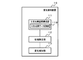
- FIG. 16 is a block diagram showing the main parts of the change detection device.
- the change detection device 10 shown in FIG. 16 includes a three-dimensional structure reconstruction unit (three-dimensional structure reconstruction means) 11 (three-dimensional structure reconstruction means) 11 (in the embodiment, three realized by the dimensional structure reconstruction units 110 and 111), and a phase removal unit (phase removal Means) 12 (implemented by phase removing units 120, 220, 320, and 330 in the embodiment) and generating a coherence image from the phase-removed SAR image pair, and calculating the coherence of the pixels constituting the coherence image.
- a change detection unit (change detection means) 13 (implemented by coherent change detection units 130 and 230 in the embodiment) that detects a change in the observation region based on the value is provided.
- FIG. 17 is a block diagram showing the main part of another aspect of the change detection device.
- the three-dimensional structure reconstructing unit 11 estimates three-dimensional point cloud data having reflection intensity and phase information using SAR tomography as a three-dimensional structure.
- a data estimation unit 11A (implemented by the three-dimensional structure reconstruction unit 110 in the embodiment) is included.
- FIG. 18 is a block diagram showing the main parts of a change detection device according to still another embodiment.
- the three-dimensional structure reconstruction unit 11 uses data including three-dimensional information (for example, three-dimensional point cloud data by LiDAR) to obtain reflection intensity and phase information in the SAR image.
- 3D point cloud data conversion unit 11B for estimating the 3D point cloud data having .
- 3D structure reconstruction means for reconstructing a 3D structure of a predetermined area in the observation area; phase removing means for removing phase signals of the predetermined region in a plurality of SAR images in which the observation region is captured, using the three-dimensional structure;
- a change detection device that generates a coherence image from a phase-removed SAR image pair and detects a change in the observation area based on coherence values of pixels that form the coherence image.
- the three-dimensional structure reconstruction means includes three-dimensional point cloud data estimation means for estimating three-dimensional point cloud data having reflection intensity and phase information using SAR tomography as a three-dimensional structure. 1 change detection device.
- the phase removing means removes the phase signal of the predetermined region in each SAR image in the SAR image group acquired by the radar mounted on the flying object,
- the change detection means generates a coherence image from a plurality of SAR image pairs selected from the SAR image group, and the coherence image includes a coherence value having a larger difference from a typical coherence value than a predetermined value.
- the change detection device according to appendix 1 or appendix 2, which detects a change in the observation region based on whether or not a coherence image exists.
- Appendix 4 The change detection device according to any one of Appendices 1 to 3, wherein the phase removing means removes phase signals of pixels whose intensity is greater than a predetermined intensity value in the SAR image.
- the three-dimensional structure reconstruction means includes three-dimensional point cloud data conversion means for estimating three-dimensional point cloud data having reflection intensity and phase information in the SAR image using data including three-dimensional information.
- a change detection method comprising generating a coherence image from a phase-removed SAR image pair and detecting a change in the observation region based on coherence values of pixels forming the coherence image.
- Appendix 7 The change detection method of Appendix 6, in which 3D point cloud data having reflection intensity and phase information is estimated using SAR tomography as the 3D structure.
- Appendix 12 The computer readout of Appendix 11, which stores a change detection program that causes the computer to execute a process of estimating three-dimensional point cloud data having reflection intensity and phase information using SAR tomography as a three-dimensional structure. Possible recording media.
- SAR image storage unit 800 LiDAR Data storage unit 1000 CPU 1001 storage device 1002 memory
Landscapes
- Engineering & Computer Science (AREA)
- Remote Sensing (AREA)
- Radar, Positioning & Navigation (AREA)
- Physics & Mathematics (AREA)
- Electromagnetism (AREA)
- Computer Networks & Wireless Communication (AREA)
- General Physics & Mathematics (AREA)
- Radar Systems Or Details Thereof (AREA)
Priority Applications (4)
| Application Number | Priority Date | Filing Date | Title |
|---|---|---|---|
| JP2023504909A JP7582444B2 (ja) | 2021-03-09 | 2021-03-09 | 変化検知装置および変化検知方法 |
| US18/280,384 US20240077605A1 (en) | 2021-03-09 | 2021-03-09 | Change detection device and change detection method |
| PCT/JP2021/009209 WO2022190196A1 (ja) | 2021-03-09 | 2021-03-09 | 変化検知装置および変化検知方法 |
| EP21930053.0A EP4307002A4 (en) | 2021-03-09 | 2021-03-09 | CHANGE DETECTION DEVICE AND CHANGE DETECTION METHOD |
Applications Claiming Priority (1)
| Application Number | Priority Date | Filing Date | Title |
|---|---|---|---|
| PCT/JP2021/009209 WO2022190196A1 (ja) | 2021-03-09 | 2021-03-09 | 変化検知装置および変化検知方法 |
Publications (1)
| Publication Number | Publication Date |
|---|---|
| WO2022190196A1 true WO2022190196A1 (ja) | 2022-09-15 |
Family
ID=83226394
Family Applications (1)
| Application Number | Title | Priority Date | Filing Date |
|---|---|---|---|
| PCT/JP2021/009209 Ceased WO2022190196A1 (ja) | 2021-03-09 | 2021-03-09 | 変化検知装置および変化検知方法 |
Country Status (4)
| Country | Link |
|---|---|
| US (1) | US20240077605A1 (https=) |
| EP (1) | EP4307002A4 (https=) |
| JP (1) | JP7582444B2 (https=) |
| WO (1) | WO2022190196A1 (https=) |
Cited By (2)
| Publication number | Priority date | Publication date | Assignee | Title |
|---|---|---|---|---|
| WO2024159812A1 (zh) * | 2023-08-09 | 2024-08-08 | 广东省国土资源测绘院 | 一种融合多源sar数据的耕地非农化图斑提取方法及设备 |
| WO2025100281A1 (ja) * | 2023-11-08 | 2025-05-15 | 日本電気株式会社 | 情報処理装置、情報処理方法及び記録媒体 |
Families Citing this family (1)
| Publication number | Priority date | Publication date | Assignee | Title |
|---|---|---|---|---|
| WO2023073936A1 (ja) * | 2021-10-29 | 2023-05-04 | 日本電気株式会社 | 信号処理システムおよび信号処理方法 |
Citations (7)
| Publication number | Priority date | Publication date | Assignee | Title |
|---|---|---|---|---|
| JP2008185375A (ja) | 2007-01-29 | 2008-08-14 | Mitsubishi Electric Corp | Sar画像の3d形状算出装置及びsar画像の歪補正装置 |
| WO2008125929A2 (en) * | 2007-02-14 | 2008-10-23 | Universita' Di Pisa | Method for processing multi-pass radar data for sensing and analysing multiple components of non-stationary scatterers |
| WO2015008310A1 (en) * | 2013-07-19 | 2015-01-22 | Consiglio Nazionale Delle Ricerche | Method for filtering of interferometric data acquired by synthetic aperture radar (sar) |
| WO2015151134A1 (ja) * | 2014-04-04 | 2015-10-08 | 三菱電機株式会社 | レーダ信号処理装置 |
| WO2019087673A1 (ja) * | 2017-10-30 | 2019-05-09 | 日本電気株式会社 | 画像処理装置、画像処理方法、画像処理プログラムおよび画像処理システム |
| EP3540462A1 (en) | 2018-03-14 | 2019-09-18 | Elta Systems Ltd. | Coherence change detection techniques |
| JP2021021703A (ja) * | 2019-07-30 | 2021-02-18 | 株式会社パスコ | 変位補正処理装置及び変位補正処理プログラム |
-
2021
- 2021-03-09 WO PCT/JP2021/009209 patent/WO2022190196A1/ja not_active Ceased
- 2021-03-09 JP JP2023504909A patent/JP7582444B2/ja active Active
- 2021-03-09 US US18/280,384 patent/US20240077605A1/en active Pending
- 2021-03-09 EP EP21930053.0A patent/EP4307002A4/en active Pending
Patent Citations (8)
| Publication number | Priority date | Publication date | Assignee | Title |
|---|---|---|---|---|
| JP2008185375A (ja) | 2007-01-29 | 2008-08-14 | Mitsubishi Electric Corp | Sar画像の3d形状算出装置及びsar画像の歪補正装置 |
| WO2008125929A2 (en) * | 2007-02-14 | 2008-10-23 | Universita' Di Pisa | Method for processing multi-pass radar data for sensing and analysing multiple components of non-stationary scatterers |
| WO2015008310A1 (en) * | 2013-07-19 | 2015-01-22 | Consiglio Nazionale Delle Ricerche | Method for filtering of interferometric data acquired by synthetic aperture radar (sar) |
| WO2015151134A1 (ja) * | 2014-04-04 | 2015-10-08 | 三菱電機株式会社 | レーダ信号処理装置 |
| WO2019087673A1 (ja) * | 2017-10-30 | 2019-05-09 | 日本電気株式会社 | 画像処理装置、画像処理方法、画像処理プログラムおよび画像処理システム |
| EP3540462A1 (en) | 2018-03-14 | 2019-09-18 | Elta Systems Ltd. | Coherence change detection techniques |
| US20190285741A1 (en) * | 2018-03-14 | 2019-09-19 | Elta Systems Ltd. | Coherence change detection techniques |
| JP2021021703A (ja) * | 2019-07-30 | 2021-02-18 | 株式会社パスコ | 変位補正処理装置及び変位補正処理プログラム |
Non-Patent Citations (1)
| Title |
|---|
| See also references of EP4307002A4 |
Cited By (2)
| Publication number | Priority date | Publication date | Assignee | Title |
|---|---|---|---|---|
| WO2024159812A1 (zh) * | 2023-08-09 | 2024-08-08 | 广东省国土资源测绘院 | 一种融合多源sar数据的耕地非农化图斑提取方法及设备 |
| WO2025100281A1 (ja) * | 2023-11-08 | 2025-05-15 | 日本電気株式会社 | 情報処理装置、情報処理方法及び記録媒体 |
Also Published As
| Publication number | Publication date |
|---|---|
| EP4307002A1 (en) | 2024-01-17 |
| EP4307002A4 (en) | 2024-04-17 |
| US20240077605A1 (en) | 2024-03-07 |
| JP7582444B2 (ja) | 2024-11-13 |
| JPWO2022190196A1 (https=) | 2022-09-15 |
Similar Documents
| Publication | Publication Date | Title |
|---|---|---|
| RU2518903C2 (ru) | Идентификация и анализ устойчивых рассеивателей в последовательности изображений, полученных с помощью sar | |
| US8154435B2 (en) | Stability monitoring using synthetic aperture radar | |
| US20180011187A1 (en) | Synthetic-aperture radar signal processing apparatus | |
| US11520035B2 (en) | Coherence change detection techniques | |
| WO2022190196A1 (ja) | 変化検知装置および変化検知方法 | |
| CN109752715B (zh) | 一种sar数据全散射体探测方法及装置 | |
| JP6452586B2 (ja) | 画像処理装置および画像処理方法 | |
| CN106910177B (zh) | 一种局域图像指标最优化的多角度sar图像融合方法 | |
| US12332344B2 (en) | Method for georeferencing of a digital elevation model | |
| CN116299455B (zh) | 基于PSInSAR与SqueeSAR的设施形变分析方法 | |
| Schmitt et al. | Maximum-likelihood estimation for multi-aspect multi-baseline SAR interferometry of urban areas | |
| CN112711021B (zh) | 一种多分辨率InSAR交互干涉时序分析方法 | |
| CN108132468B (zh) | 一种多基线极化干涉sar建筑物高度提取方法 | |
| CN114966690B (zh) | 一种gnss-r sar双星融合成像方法及系统 | |
| CN108957452A (zh) | 一种合成孔径雷达自适应ffbp成像方法 | |
| US20240193856A1 (en) | Signal processing device and signal processing method | |
| Lombardini et al. | Linear and adaptive spaceborne three-dimensional SAR tomography: A comparison on real data | |
| KR102185307B1 (ko) | Sar 영상의 객체 응답 초해상도화 방법 및 객체 응답 초해상도화 장치 | |
| CN103176171B (zh) | 一种干涉sar分布目标仿真方法 | |
| CN111707996A (zh) | 基于改进grft-stap的geo星机sar动目标检测方法 | |
| CN117761716B (zh) | 融合CR和GNSS的InSAR滑坡形变时序监测方法和存储介质 | |
| CN118534462A (zh) | 一种面向配准的多频点sar一致性频域成像处理方法 | |
| JP7722453B2 (ja) | 画像解析装置および画像解析方法 | |
| Lim et al. | Autofocus algorithms performance evaluations using an integrated SAR product simulator and processor | |
| CN118584435B (zh) | 基于参考面的雷达差分干涉像对的误差校正方法及系统 |
Legal Events
| Date | Code | Title | Description |
|---|---|---|---|
| 121 | Ep: the epo has been informed by wipo that ep was designated in this application |
Ref document number: 21930053 Country of ref document: EP Kind code of ref document: A1 |
|
| WWE | Wipo information: entry into national phase |
Ref document number: 2023504909 Country of ref document: JP |
|
| WWE | Wipo information: entry into national phase |
Ref document number: 18280384 Country of ref document: US |
|
| WWE | Wipo information: entry into national phase |
Ref document number: 2021930053 Country of ref document: EP |
|
| NENP | Non-entry into the national phase |
Ref country code: DE |
|
| ENP | Entry into the national phase |
Ref document number: 2021930053 Country of ref document: EP Effective date: 20231009 |