WO2022186171A1 - センシングデバイス - Google Patents
センシングデバイス Download PDFInfo
- Publication number
- WO2022186171A1 WO2022186171A1 PCT/JP2022/008485 JP2022008485W WO2022186171A1 WO 2022186171 A1 WO2022186171 A1 WO 2022186171A1 JP 2022008485 W JP2022008485 W JP 2022008485W WO 2022186171 A1 WO2022186171 A1 WO 2022186171A1
- Authority
- WO
- WIPO (PCT)
- Prior art keywords
- sensor
- sensing device
- user terminal
- screen
- alert
- Prior art date
- Legal status (The legal status is an assumption and is not a legal conclusion. Google has not performed a legal analysis and makes no representation as to the accuracy of the status listed.)
- Ceased
Links
Images


Classifications
-
- A—HUMAN NECESSITIES
- A47—FURNITURE; DOMESTIC ARTICLES OR APPLIANCES; COFFEE MILLS; SPICE MILLS; SUCTION CLEANERS IN GENERAL
- A47C—CHAIRS; SOFAS; BEDS
- A47C31/00—Details or accessories for chairs, beds, or the like, not provided for in other groups of this subclass, e.g. upholstery fasteners, mattress protectors, stretching devices for mattress nets
- A47C31/12—Means, e.g. measuring means, for adapting chairs, beds or mattresses to the shape or weight of persons
-
- A—HUMAN NECESSITIES
- A61—MEDICAL OR VETERINARY SCIENCE; HYGIENE
- A61G—TRANSPORT, PERSONAL CONVEYANCES, OR ACCOMMODATION SPECIALLY ADAPTED FOR PATIENTS OR DISABLED PERSONS; OPERATING TABLES OR CHAIRS; CHAIRS FOR DENTISTRY; FUNERAL DEVICES
- A61G5/00—Chairs or personal conveyances specially adapted for patients or disabled persons, e.g. wheelchairs
- A61G5/10—Parts, details or accessories
- A61G5/12—Rests specially adapted therefor, e.g. for the head or the feet
Definitions
- the present invention relates to a sensing device that is attached to various seating tools such as wheelchairs and car seats, or that is worn by wheelchair users.
- Patent Document 1 As a system for monitoring the sitting posture of a seated person, a pressure distribution sensor that detects the distribution of pressure acting on the seat surface and the back surface of a chair, converts it into an electrical signal and outputs it, and the pressure obtained from the pressure distribution sensor A device provided with a posture estimation device for estimating a sitting posture based on information has been proposed (Patent Document 1).
- the pressure distribution sensor used in this monitoring system is woven with a warp containing conductive yarns in which a conductive fiber core yarn is covered with an insulating sheath yarn, and a weft yarn containing conductive yarns with a similar structure. It is composed of a conductive woven fabric, and a cell (pressure-sensitive part) is formed in a portion where the warp conductive yarn and the weft conductive yarn are woven together.
- the pressure distribution sensor used in the monitoring system of Patent Document 1 calculates a relative voltage from changes in capacitance between conductive threads, and the pressure applied to each pressure sensing part is taken as an absolute value. cannot be specified.
- the present invention has been made in view of such circumstances, and the problem to be solved is to provide a sensing device that can specify the pressure applied to each pressure sensing portion as an absolute value.
- the sensing device of the present invention is a device for detecting pressure applied to a seating tool, and includes a seat surface part arranged on the seat surface of the seating tool or a lower garment worn by a seated person on the lower body.
- a plurality of sensors are provided in the thigh region and the buttock region of the seat or lower clothing.
- a pressure sensor is used as the sensor, which calculates the pressure applied to the sensor based on the electrical resistance value.
- the sensing device of the present invention uses a pressure sensor that calculates the pressure applied to the sensor based on the electrical resistance value of the sensor, the pressure applied to the pressure sensing part (sensor) can be specified as an absolute value, It helps to build a system that conveys accurate information to the seated person.
- FIG. 4 is a configuration explanatory diagram of a control unit and a sensor unit
- FIG. 2 is a hardware configuration diagram of a management server
- FIG. 4 is a configuration explanatory diagram of a management server
- (a) is an explanatory diagram showing an example of a table prepared in the user information storage unit
- (b) is an explanatory diagram showing an example of a table prepared in the sensor information storage unit
- (c) is prepared in the alert information storage unit.
- FIG. 2 is a hardware configuration diagram of a user terminal
- FIG. 10 is a sequence diagram when logging in using a user terminal
- (a) is an explanatory diagram showing an example of a login screen
- (b) is an explanatory diagram showing an example of a main menu displayed on a main screen.
- FIG. 10 is a sequence diagram when user registration is performed using a user terminal; Explanatory drawing which shows an example of a user information registration screen.
- FIG. 4 is a sequence diagram when referring to data using a user terminal; (a) is an explanatory diagram showing an example of a data reference screen, and (b) is an explanatory diagram of a seat surface heat map and a displacement force map.
- FIG. 10 is a sequence diagram when making an action inquiry using a user terminal; Explanatory drawing which shows an example of an action inquiry screen.
- FIG. 4 is a sequence diagram when various settings are performed using a user terminal; Explanatory drawing which shows an example of a setting screen.
- FIG. 10 is a sequence diagram when referring to an advice list using a user terminal; FIG.
- FIG. 4 is an explanatory diagram showing an example of an advice list screen
- FIG. 10 is a sequence diagram when inquiring about specific advice using a user terminal
- Explanatory drawing which shows an example of an advice inquiry screen.
- FIG. 10 is a sequence diagram when inquiring the details of a specific alert from the advice inquiry screen displayed on the user terminal
- FIG. 10 is a sequence diagram when inquiring the details of a specific alert from the advice list screen displayed on the user terminal
- FIG. 10 is a sequence diagram when deleting specific advice from the advice list screen displayed on the user terminal
- FIG. 10 is a sequence diagram when inquiring about specific advice using a user terminal
- Explanatory drawing which shows an example of an advice inquiry screen.
- FIG. 10 is a sequence diagram when inquiring the details of a specific alert from the advice inquiry screen displayed on the user terminal
- FIG. 10 is a sequence diagram when inquiring the details of a specific alert from the advice list screen displayed on the user terminal
- FIG. 10 is a sequence diagram when
- FIG. 10 is a sequence diagram when newly registering advice through the user terminal; (a) is an explanatory diagram showing an example of a new advice input screen, and (b) is an explanatory diagram showing an example of a new advice input screen.
- the sequence diagram when referring to the alert list from the main screen displayed on the user terminal.
- (a) is an explanatory diagram showing an example of an alert list screen
- (b) is an explanatory diagram showing an example of an alert inquiry screen.
- the sequence diagram when inquiring the details of a specific alert from the alert list screen displayed on the user terminal.
- FIG. 11 is a sequence diagram when referring to advice related to the alert from the alert inquiry screen displayed on the user terminal; Detailed explanatory drawing of the pressure sensor using a conductive thread.
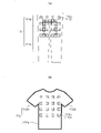
- (a) is an explanatory diagram showing an example of a lower-side garment
- (b) is an explanatory diagram showing an example of an upper-garment-side garment.
- FIG. 1 shows the overall configuration of the pressure ulcer prevention system of this embodiment.
- the pressure ulcer prevention system of this embodiment includes a seating device 10, a management server 30, and a user terminal 50 used by each user.
- the seating device 10 and each user terminal 50 are connected to the management server 30 via a communication network N so as to be communicable.
- users include wheelchair users, physical therapists, caregivers (helpers), family members, medical personnel (doctors and nurses), insurance personnel, care managers, welfare equipment counselors, local governments, etc. is assumed.
- the user terminal 50 used by the wheelchair user will be referred to as the seat user terminal or the wheelchair user terminal
- the user terminal 50 used by the person providing the advice will be referred to as the advice provider terminal. be.
- the seating device 10 in the pressure ulcer prevention system of this embodiment is an installation-type sensing device 100 (hereinafter referred to as "installation-type device") that is installed on a wheelchair X for use.
- a seating device 10 shown in FIG. 2 as an example comprises a sensor unit 11 and a control unit 12 .
- the sensor unit 11 is arranged on the front side of the seat surface X1 and the backrest (back support) X2 of the wheelchair X, and the control unit 12 can be installed at any position of the wheelchair X, for example, the back side or side surface of the backrest X2, or the back of the seat surface. , lower net, etc.
- the size of the control unit 12 can be adjusted according to the mounting position.
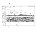
- the sensor unit 11 shown in FIGS. 2 and 3 (a) and (b) includes a sensor sheet 13, a sensor 14, and a seat cover 15.
- the sensor unit 11 of this embodiment includes a seat surface portion 11a that is arranged on the seat surface X1 of the wheelchair X and detects the pressure applied to the seat surface X1, and a seat surface portion 11a that is arranged in front of the backrest X2 of the wheelchair X and detects the pressure applied to the seat surface X1.
- a back portion 11b is provided to detect the pressure applied to the lean X2.
- the sensor sheet 13 is a sheet for attaching the sensor 14 .
- the sensor sheet 13 of this embodiment includes a seat surface sheet 13a and a back sheet 13b.
- Various materials can be used for the sensor sheet 13, but in this embodiment, a sheet made of a flexible and waterproof material is used.
- the seat surface sheet 13a and the back sheet 13b are configured as separate members, but they can also be configured as an integrated product.
- the sensor 14 detects the pressure applied to the buttocks and back of the seated wheelchair user and converts it into an electrical signal.
- a pressure sensor, a load vector sensor, or the like can be used as the sensor 14 .
- a pressure sensor with an effective sensor area of 39.6 mm ⁇ 39.6 mm, a thickness of 0.20 to 1.25 mm, a pressure sensing range of 0.2 to 20 N, and a minimum sensitivity of 20 to 100 g is used as the sensor 14.
- This pressure sensor is a kind of polymer thick film, and the resistance value decreases when pressure (load) is applied to the sensor part.
- a graph showing the resistance characteristic of this pressure sensor is a curve in which the resistance value gradually decreases as the load increases.
- the sensor 14 is arranged as an independent sensor at each measurement point.
- the load (pressure) applied to each sensor 14 is calculated by back calculation from the electrical resistance measured for each sensor 14 .
- the pressure applied to each sensor 14 can be specified as an absolute value regardless of the measured values of the other sensors 14 .
- the seat 13a has 32 sensors (hereinafter referred to as “seat sensors”) 14a
- the back sheet 13b has 16 sensors (hereinafter referred to as “back sensors”). ) 14b is provided.
- Thirty-two seat surface sensors 14a provided on the seat surface sheet 13a are arranged on the portion (thigh area) where the right and left thighs of the wheelchair user are located and the portion (buttock area) where the buttocks are located (buttock area). They are arranged in a substantially U-shape. Each of the portions corresponding to the two U-shaped arms constitutes the thigh region, and the portion corresponding to the U-shaped connecting portion (the portion connecting the two arms) is the buttocks. Configure a region.
- the seat 13a is provided with a non-installation area 14c where the seat sensor 14a is not installed.
- the non-installation area 14c referred to here is an area to be interpolated in the display of the seat surface heat map 81, which will be described later.
- the non-installation area 14c can be ⁇ upper right, lower right, upper left, lower left), (a) two or more of the four directions of top, bottom, left, right, and (b) one of the four directions of top, bottom, left, right
- An area surrounded by the currently installed seat sensor 14a in one direction and two or more of the upper right, lower right, upper left, and lower left, or (c) three or more of the upper right, lower right, upper left, and lower left. includes.
- the number of seat sensors 14a can be minimized by providing the seat 13a (seat portion 11a) with a non-installation region 14c where no seat sensors 14a are arranged.
- the time for transmitting data to the management server 30 can be shortened, and a system capable of transmitting information to wheelchair users in real time can be constructed.
- Real time in the present application is not limited to simultaneous cases in the strict sense, but is a concept that includes the time generated for performing various processing such as data communication, analysis, recording, etc., and a few seconds after acquiring data (for example , 4 to 6 seconds).
- each thigh area 3, 1, 3, 1 are arranged from front to back, and in the buttock area, from front to back, , 7, 5, 4, and so on.
- the seat surface sensor 14a In the thigh area, there are a number of seating surface sensors 14a arranged in the left-right direction, such as three, one, three to one, three, and one (three in the example of the figure), and a few. By staggering the locations (one in the example shown in the figure) along the front-rear direction, the seat surface sensor 14a has locations where it is arranged in a fish-bone shape.
- the seat surface sensors 14a are arranged such that seven in the front and four in the rear in the buttock region, so that there is no non-installation region 14c in the front and the non-installation region 14c in the rear. It has an arranged part.
- the arrangement of the seat surface sensor 14a shown here is an example, and the seat surface sensor 14a can be arranged in other ways.
- the 16 rear sensors 14b provided on the rear sheet 13b are arranged at equal intervals from top to bottom in the order of 4, 4, 4, 4. there is The arrangement of the rear surface sensor 14b shown here is an example, and the rear surface sensor 14b may be arranged in a different arrangement.
- the first quadrant A1 the lower right area is called the second quadrant A2
- the lower left area is called the third quadrant A3
- the upper left area is called the fourth quadrant A4.
- the region B2 the region above the front-rear dividing line L1 (the first quadrant A1 and the fourth quadrant A4) is a front region B3, and the region below the same (the second quadrant A2 and the third quadrant A3) is the rear region B4. It says.
- the seat cover 15 covers the sensor sheet 13 and the sensor 14 attached to the sensor sheet 13 .
- the seat cover 15 of this embodiment includes a seat cover 15a that covers the seat 13a and the seat sensor 14a, and a back cover 15b that covers the back seat 13b and the back sensor 14b.
- Various materials can be used for the seat cover 15, but in this embodiment, a sheet made of a flexible and waterproof material is used.
- the control unit 12 is a unit for controlling the sensor unit 11. As shown in FIG. 4, the control unit 12 of this embodiment includes a microcomputer 16, a battery 17, and a communication module 18. FIG. The microcomputer 16 , battery 17 and communication module 18 are housed in a housing box 19 .
- the microcomputer 16 processes the signals acquired by the seat sensor 14a and the back sensor 14b and transmits the signals to the management server 30 via the communication module 18.
- the microcomputer 16 is composed of a microcomputer board 16a and various electronic components 16b mounted on the microcomputer board 16a.
- an chicken or the like can be used for the microcomputer board 16a.
- a communication module 18 for transmitting data acquired by the sensor 14 to the management server 30 is connected to the microcomputer 16 .
- the communication module 18 for example, 3GIM (3GIoT Module) or the like can be used.
- the communication module 18 one having a GPS (Global Positioning System) function can also be used.
- GPS Global Positioning System
- the GPS module can also be provided separately from the communication module 18 .
- one microcomputer board 16a is connected to 16 sensors 14, as shown in FIG.
- a sensor 14 is connected to each microcomputer board 16a by wire, and each microcomputer board 16a acquires data from the 16 sensors 14 assigned thereto.
- Serial communication is performed between the microcomputer boards 16a, and data acquired by the microcomputer boards 16a is transmitted to the management server 30 via the common communication module 18.
- FIG. the case of using a plurality of microcomputer boards 16a is taken as an example, but it is also possible to configure so that all the sensors 14 are connected to one microcomputer board 16a.
- a common battery 17 is connected to each microcomputer board 16a, and power is supplied from the battery 17 to each microcomputer board 16a.
- An existing lithium ion secondary battery or the like can be used for the battery 17 .
- the battery 17 and each microcomputer board 16a are connected in a storage box 19. FIG.
- the acquired data is transmitted to the management server 30 every few seconds from the viewpoint of transmitting information to the wheelchair user in real time. Data can be sent at shorter or longer intervals.
- the transmitted data is processed in the management server 30 . Processing by the management server 30 will be described later.
- the configuration of the seating device 10 described above is merely an example, and the seating device 10 may have other configurations as long as the intended purpose can be achieved.
- the management server 30 is a so-called cloud server (cloud system) that acquires, processes, aggregates, records, and updates data transmitted from the seating device 10, and responds to requests from each user terminal 50, and the like.
- cloud server cloud system
- the management server 30 of this embodiment includes a processor 31, a memory 32, a storage 33, a communication section 34, an input section 35, and an output section 36 as main components. These elements are electrically connected through a bus 37 .
- the management server 30 is configured to include a power source, a storage device, an uninterruptible power source, a backup device, etc. so as to stably provide services to a plurality of user terminals 50. is preferred.
- the processor 31 comprehensively controls each component connected by the bus 37, and is composed of, for example, a CPU (Central Processing Unit) and an MPU (Micro Processing Unit).
- the processor 31 loads application programs necessary for executing processing from the storage 33 to the memory 32 and executes each processing.
- the memory 32 is a main storage device that stores data and instructions, and is composed of, for example, ROM (Read Only Memory) and RAM (Random Access Memory).
- the storage 33 is an auxiliary storage device that stores programs and data, and is composed of, for example, a HDD (Hard Disk Drive), SSD (Solid State Drive), flash memory, and the like.
- the storage 33 stores an application program for the pressure ulcer prevention system of this embodiment.
- the communication unit 34 is a communication interface for performing wireless communication (data communication) with the seating device 10 and each user terminal 50 via the communication network N, and includes TCP/IP, Bluetooth Low Energy (registered trademark), Communication is performed according to various communication standards such as Bluetooth (registered trademark), 3G (3rd Generation), 4G (4th Generation), and LTE (Long Term Evolution).
- the communication unit 34 includes a receiving unit 34a and a transmitting unit 34b.
- the receiving unit 34 a receives a signal from each user terminal 50 , decodes the received signal, and transmits the decoded signal to the processor 31 .
- the transmission unit 34b transmits the information transmitted from the processor 31 to each user terminal 50.
- the input unit 35 is a device for inputting information, and is composed of, for example, a keyboard, touch screen, mouse, voice input device, and the like.
- the output unit 36 is a device for outputting information, and includes a display, a printer, and the like.
- the management server 30 can be composed of two or more server groups. As shown in FIG. 6, the management server 30 of this embodiment includes a web server (hereinafter referred to as “web server") 300, an application server (hereinafter referred to as “AP server”) 320, and A database server (hereinafter referred to as “DB server”) 340 is provided.
- web server hereinafter referred to as "web server”
- AP server application server
- DB server database server
- the web server 300 is a server that provides web services in response to requests from user terminals 50 .
- the Web server 300 of this embodiment comprises a request reception unit 301, a processing request unit 302, a result reception unit 303, and a response screen generation unit 304 as main components.
- the request reception unit 301 is a function unit that receives a request from the user terminal 50
- the processing request unit 302 is a function unit that requests processing from the AP server 320
- the result reception unit 303 receives a processing result sent from the AP server 320.
- a functional unit, the response screen generation unit 304 is a functional unit that generates a screen to be transmitted to the user terminal 50 .
- the AP server 320 is a server that executes application programs based on requests from the Web server 300 .
- the AP server 320 of this embodiment mainly includes a preprocessing unit 321, a request reception unit 322, a user registration unit 323, a chart generation unit 324, an alert determination unit 325, an action determination unit 326, an advice reception unit 327, and a reservation reception unit 328. It is provided as a structure.
- the preprocessing unit 321 is a functional unit that formats data transmitted from the seating device 10
- the request reception unit 322 is a functional unit that receives requests from the web server 300
- the user registration unit 323 is a functional unit that executes user registration processing.
- the diagram generation unit 324 is a function unit that generates heat maps 81 and 82, a shear force map 83, various lists, graphs, etc. in response to a request from the Web server 300.
- An alert determination unit 325 satisfies alert conditions based on data.
- An advice reception unit 327 is a function unit that receives new advice registration
- a reservation reception unit 328 is a function unit that receives reservations for remote rehabilitation.
- the preprocessing unit 321 shapes the raw data (a series of numbers in which the measurement data for 4 seconds are collected) acquired by the seating device 10 into data for each second, and the data obtained by shaping (hereinafter referred to as “shaped data ”), the number of operations is totaled at intervals of one minute. Shaping data and data obtained by aggregation (hereinafter referred to as “aggregated data”) are stored in the sensor information storage unit 342 of the DB server 340 .
- the diagram generation unit 324 generates heat maps 81 and 82, a shear force map 83, various lists, graphs, and the like.
- a seat heat map 81 and a back heat map 82 are generated as heat maps.
- the seat surface heat map 81 combines the pressure value of the seat surface portion 11a detected by the seat surface sensor 14a of the seating device 10 and the interpolated value of the non-installation region 14c calculated from the pressure value into the seat surface portion 11a (seat surface X1 ) is color-coded according to the value of the pressure (seat pressure).
- the seat surface heat map 81 includes a data reference screen 63, an advice inquiry screen 67 (see FIG. 24), a new advice input screen 68 (see FIG. 29(a)), and an alert inquiry screen 70 (see FIG. 31(b)). to be displayed. In this embodiment, when the cursor is placed on an arbitrary area on the seat surface heat map 81, the seating pressure of that area is displayed.
- the back surface heat map 82 displays the pressure values of the back surface portion 11b detected by the back surface sensor 14b of the seating device 10 as the pressure applied to the back surface portion 11b (backrest X2) in different colors according to the value. be.
- the back surface heat map 82 includes a data reference screen 63 (see FIGS. 14A, 14B, 16A, and 16B), an advice inquiry screen 67 (see FIG. 24), and a new advice input screen 68 (see FIG. 24). 29(a)) and displayed on the alert inquiry screen 70 (see FIG. 31(b)).
- the cursor is placed on an arbitrary area on the back heat map 82, the sitting pressure of that area is displayed.
- the deviation force map 83 is a chart showing the shear force (deviation force) applied to the buttocks of the wheelchair user.
- the displacement force is calculated from the pressure value of the seat portion 11a acquired by the seat sensor 14a and the pressure value of the back portion 11b acquired by the back sensor 14b.
- the shear force can also be calculated in other ways.
- pressure ulcers on the back can be prevented.
- the back may rub against the back and lead to injuries and bedsores.
- pressure ulcers on the back can be prevented by issuing an alert when it is determined that excessive pressure is applied to the back from the pressure value of the back portion 11b acquired by the back sensor 14b. can be done.
- the displacement force can be displayed in various ways, but in this embodiment, as shown in FIG.
- the vector is not displayed in the portion where the displacement force does not act.
- the deviation force is displayed as a vector, and by placing the cursor on the displayed arrow, the numerical value of the deviation force at the portion where the arrow is displayed is displayed.
- the displacement force map 83 includes a data reference screen 63 (see FIGS. 14A, 14B, 16A, and 16B), an advice inquiry screen 67 (see FIG. 24), and a new advice input screen 68 (see FIG. 24). 29(a)) and displayed on the alert inquiry screen 70 (see FIG. 31(b)).
- the displacement force map 83 can also be displayed independently without being superimposed on the seat surface heat map 81 . Specifically, in the area where the seat heat map 81 is displayed, the seat heat map 81 may not be displayed, and only the displacement force map 83 may be displayed.
- the chart generation unit 324 in addition to the heat maps 81 and 82 and the slippage force map 83, the chart generation unit 324 generates an advice list 92 in which advices are displayed in a list, an alert list 93 in which alerts are displayed in a list, and data recorded in the past. , and an action item list 91 in which information about each action item is listed.
- the advice list 92 includes, for example, "inquiry column”, “no column”, “category column”, “date column”, “flag column”, “advice column”, “alert No./category column”, “alert detail column”, and “delete column”. is included.
- the advice list 92 is displayed on an advice list screen 66 (see FIG. 22), which will be described later.
- the alert list 93 includes, for example, "inquiry column”, “no column”, “category column”, “date column”, “flag column”, “alert content column”, and "related advice column”.
- the alert list 93 is displayed on an alert list screen 69, which will be described later (see FIG. 31(a)).
- the action item list 91 a list of the number of actions for today, the average number of actions for the period, and the number of actions for the target value is displayed.
- the action items include, for example, wheelchair ride time, number of rides, push-up (long/short), weight shift left (long/short), weight shift right (long/short), and active.
- the action item list 91 includes a data reference screen 63 (see FIGS. 16A and 16B), an advice inquiry screen 67 (see FIG. 24), and a new advice input screen 68 (see FIG. )) and the alert inquiry screen 70 (see FIG. 31(b)).
- the diagram generation unit 324 generates a displacement force graph 84, a seat pressure graph 85, and an action graph 86.
- the shear force graph 84 displays the change in the shear force at three specified points (right sitbone, left sitbone, and sacrum), and the seat pressure graph 85 shows the change in seat pressure at the three specified points (right sitbone, left sitbone, and sacrum). is displayed, and the behavior graph 86 indicates the number of times and time of behavior in a specified period.
- the diagram shown here is an example, and the diagram generation unit 324 can also generate diagrams other than these.
- the alert determination unit 325 determines whether the data within a predetermined time period satisfies preset alert conditions, generates an alert when the alert conditions are satisfied, and transmits the alert to the Web server 300 . In this embodiment, an alert is transmitted to the wheelchair user terminal 50 via the communication unit 34 when the following conditions are met.
- the first alert is a high pressure alert.
- a high pressure alert is issued when the pressure average for 30 minutes in each of the first quadrant A1 to the fourth quadrant A4 exceeds a preset reference value.
- the alert determination unit 325 determines that the pressure average for 30 minutes in the first quadrant A1 has exceeded a preset reference value
- the alert determination unit 325 detects a high pressure state of the right front seat pressure. ” and transmits the high pressure alert to the Web server 300 .
- the web server 300 that has received the high pressure alert transmits the high pressure alert to the user terminal 50 via the communication unit 34 .
- the second alert is an insufficient pressure release alert.
- the insufficient pressure relief alert searches the pressure relief event log (push-up and weight shift) for the past hour every 30 minutes, and is issued when the pressure relief does not reach the preset target value.
- the alert determination unit 325 determines that the number of right push-ups (long) in the past hour has not reached the preset target value
- the alert determination unit 325 displays the message, "Right pressure is insufficient.”
- a depressurization shortage alert is generated and the depressurization shortage alert is transmitted to the web server 300 .
- the Web server 300 that has received the insufficient pressure-removal alert transmits the insufficient pressure-removal alert to the user terminal 50 via the communication unit 34 .
- the third alert is the high shear force alert.
- the high shear force alert is issued when 30 minutes have passed while the shear force applied to the seat surface sensor 14a is higher than a preset reference value.
- a high shear force alert is generated if there is at least one point where the shear force is higher than the reference value.
- the alert determination unit 325 determines that 30 minutes have passed while the pressure average in the first quadrant A1 exceeds the preset reference value, the alert determination unit 325 generates a high shear force alert, The high deviation force alert is transmitted to the web server 300 .
- the web server 300 that has received the high shear force alert transmits the high shear force alert to the user terminal 50 via the communication unit 34 .
- the alert is sent to the SNS installed on the user terminal 50 (viewable on the user terminal 50).
- SNS Short Message Service
- the alert can also be sent by various methods, such as e-mail or SMS (Short Message Service) that can be viewed on the user terminal 50, so that the wheelchair user can immediately (timely) check it.
- the behavior determination unit 326 determines the user's behavior based on signals transmitted from the seating device 10 .
- Actions here include “wheelchair riding time”, “number of rides”, “push up (long/short)”, “weight shift left (long/short)”, “weight shift right (long/short)”, “active”, etc. included. Note that the actions shown here are only examples, and actions other than these may be included.
- “Wheelchair Ride Time” represents the time spent riding on wheelchair X
- “Ride Times” represents the total number of rides on wheelchair X. If the average seat pressure is 10 mmHg or more for 1 minute or more, the action determination unit 326 determines that the user is riding, and starts counting. When it continues, it judges as “disembarking” and stops counting. The time obtained at this time from getting on to getting off is counted as riding time, and the number of times of getting on and off is counted as the number of times of getting on.
- the aforementioned push-up refers to the action of lifting the buttocks with the hands as support and releasing the pressure.
- the behavior determination unit 326 counts the case where the value of all quadrants A1 to A4 is 10 mmHg or less for 3 to 15 seconds or less as a short circuit, and the state where the value of all quadrants A1 to A4 is 10 mmHg or less is 15 to 15 seconds. Count as long if it lasts less than 60 seconds.
- the weight shift refers to the movement of tilting the body to the left and right and releasing the pressure on the buttocks one by one.
- the action determination unit 326 counts a case where the pressure applied to either the left or right half of the seat surface X1 is below a certain value for 3 to 15 seconds, and counts it as a short circuit, and A state in which the pressure remains below a certain value for 15 to 60 seconds is counted as long.
- the action determination unit 326 determines that the object is active when the movement distance of the center of gravity (COP) moves by 10 cm or more in 5 seconds. Since there are times when there is little movement due to signal waiting or wheelchair driving, in this embodiment, if the center of gravity moves for 31 seconds or more in one minute, it is counted as active for one minute, and the center of gravity in one minute is counted. If the movement time is 30 seconds or less, it is determined to be inactive (end of active).
- COP center of gravity
- the advice reception unit 327 receives a registration request for new advice from the advice provider terminal 50 and stores the new advice in the advice information storage unit 344 of the DB server 340 .
- the reservation reception unit 328 is a functional unit that receives a reservation request for remote rehabilitation from the wheelchair user terminal 50 .
- the DB server 340 is a server for storing various data such as user information, sensor 14 information, alert information, and advice information. managed by
- the DB server 340 of this embodiment includes a user information storage unit 341, a sensor information storage unit 342, an alert information storage unit 343, an advice information storage unit 344, and a setting condition storage unit 345 as main components. ing.
- the alert information storage unit 343 is an area for storing information regarding alerts generated by the AP server 320
- the advice information storage unit 344 is an area for storing information regarding advice.
- the user information storage unit 341 is an area for storing information on users who use this pressure ulcer prevention system.
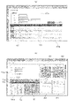
- a table as shown in FIG. 7A is prepared in the user information storage unit 341, and information such as "user ID”, "level of care required", and "disability type" is stored.
- the sensor information storage unit 342 is an area that stores information acquired by the seating device 10 and transmitted to the management server 30 side, shaping data of the information, total data obtained by tallying the shaping data, and the like.
- a table as shown in FIG. 7B is prepared in the sensor information storage unit 342, and information such as "generation time”, "raw data”, and "interpolation data" is stored.
- the alert information storage unit 343 is an area for storing information regarding alerts generated by the alert determination unit 325 .
- a table as shown in FIG. 7C is prepared in the alert information storage unit 343, and information such as "alert ID”, "date and time of generation", and "category" is stored.
- the advice information storage unit 344 is an area for storing information on new advice input from the advice provider terminal 50 .
- a table (not shown) is prepared in the advice information storage unit 344, and information such as "advice content”, “advice creation date”, and "creator" is stored.
- the setting condition storage unit 345 is an area for storing information regarding setting conditions input from the wheelchair user terminal 50 . Although illustration is omitted, a table (not shown) is prepared in the setting condition storage unit 345, and includes "left sciatic position”, “right sciatic position”, “sacral position”, “movement target value”, “action detection reference value”, and “alert reference value”. information such as "value” is stored.
- the configuration of the management server 30 described above is an example, and the management server 30 may have other configurations as long as the intended purpose can be achieved.
- the user terminal 50 is an information communication device used by wheelchair users, physical therapists, caregivers, family members, medical personnel, insurance personnel, and the like.
- the user terminal 50 of this embodiment includes a processor 51, a memory 52, a storage 53, a communication section 54, an input section 55, and an output section 56 as main components. properly connected.
- a PC a smart phone, a tablet, or the like can be used as the user terminal 50 .
- the processor 51, memory 52, storage 53, communication unit 54, input unit 55, and output unit 56 are the same as the processor 31, memory 32, storage 33, communication unit 34, input unit 35, and output unit 36. The description of the part to be performed is omitted.
- the pressure ulcer prevention system may be used by installing a dedicated application.
- the configuration of the user terminal 50 described above is just an example, and the user terminal 50 may have other configurations as long as the intended purpose can be achieved.
- the management server 30 of the pressure ulcer prevention system of this embodiment stores a program (application program) for causing the management server 30 to function as a server that performs the following processing. In response to a request from terminal 50, each of the following processes is executed.
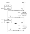
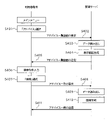
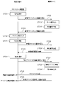
- FIG. 9 is a sequence diagram when logging in using the user terminal 50. As shown in FIG. 9, when a URL is entered on the browser of the user terminal 50 (S001), the user terminal 50 requests the login screen 60 from the management server 30 (S002).
- the management server 30 Upon receiving the request for the login screen 60, the management server 30 reads the data (S003), generates the login screen 60 (S004), and transmits the login screen 60 to the user terminal 50 (S005).
- the browser of the user terminal 50 that has received the login screen 60 displays the login screen 60 as shown in FIG. 10(a).
- the user terminal 50 enters an ID and a password (PW) in the ID input field 60a and the password input field 60b of the login screen 60 displayed on the browser of the user terminal 50 (S006), and the password is displayed below the password input field 60b. is selected (S007), login authentication is requested to the management server 30 (S008).
- the selection method includes all selection methods such as clicking a mouse, pressing an enter button on a keyboard, and touching a touch panel (the same applies hereinafter).
- the login method can be a method other than ID and password input on the login screen 60.
- a login method by authentication of other SNS services a login method linked with an external system, a login method by biometric authentication such as fingerprint authentication, face authentication, iris authentication, etc. can be used. In either case, it is preferable to use a highly secure method in consideration of security.
- the management server 30 that has received the login authentication request from the user terminal 50 authenticates the user (S009), generates the main screen 61 for the user using the user terminal 50 (S010), The main screen 61 is transmitted to the user terminal 50 (S011).
- the browser of the user terminal 50 that has received the main screen 61 displays the main screen 61 having a main menu 61a on the upper left, as shown in FIG. 10(b).
- a main menu 61a shown in FIG. 10B includes a "user information registration” button 61b, a "data reference” button 61c, an "advice” button 61d, and an “alert” button 61e.
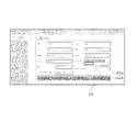
- FIG. 11 is a sequence diagram for user registration using the user terminal 50. As shown in FIG. As shown in FIG. 11, when the user terminal 50 selects the "user information registration" button 61b of the main menu 61a (FIG. 10(b)) on the browser of the user terminal 50 (S101), A user information registration screen 62 is requested from the management server 30 (S102).
- the management server 30 receives the request for the user information registration screen 62 from the user terminal 50, reads the data (S103), generates the user information registration screen 62 (S104), and transmits it to the user terminal 50 (S105). ).
- the browser of the user terminal 50 displays the user information registration screen 62 as shown in FIG.
- the user information registration screen 62 shown in FIG. 12 includes a user information input section 62a and a "Register” button 62b.
- a user information input section 62a "name”, “sex”, “date of birth”, “height”, “level of nursing care”, “wheelchair type”, “seating device ID”, “weight”, “insurance type”, “disability type”, “30 minutes”,
- An input box such as "more exercise frequency” is included.
- the registration items shown here are just an example, and other items such as “age (age)", “occupation”, “residence (address)", “walkability”, and “disabled parts” may be included. can.
- the management server 30 Upon receiving the user registration request from the user terminal 50, the management server 30 stores (registers) the user information in the user information storage unit 341 of the DB server 340 (S109) and generates a registration completion screen (not shown). (S110) and transmitted to the user terminal 50 (S111).
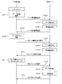
- FIG. 13 is a sequence diagram for referring to data using the user terminal 50.
- FIG. 13 As shown in FIG. 13, when the user terminal 50 selects the "data reference" button 61c from the main menu 61a (FIG. 10(b)) displayed on the user terminal 50 (S201), the management server 30 to request the data reference screen 63 (S202).
- the management server 30 receives a request for the data reference screen 63 from the user terminal 50, reads the data (S203), generates the data reference screen 63 for the user (S204), and transmits it to the user terminal 50. (S205).
- the browser of the user terminal 50 that has received the data reference screen 63 displays the data reference screen 63 as shown in FIG. 14(a).
- the data reference screen 63 of this embodiment is such that a "real time” mode and a "period designation” mode can be selected by switching between a "real time” tab 63a and a "period designation” tab 63b.
- a "real time” mode real-time data can be referred to, and in the "specified period” mode, the average value of data during an arbitrary period can be referred to.
- the management server 30 Upon receiving the request for real-time information from the user terminal 50, the management server 30 reads the data (S208), generates real-time information (S209), and transmits it to the user terminal 50 (S210). A screen including real-time information as shown in FIG. 14(a) is displayed on the browser of the user terminal 50 that has received the real-time information.
- the data reference screen 63 in the "real time" mode of this embodiment includes a seat surface heat map 81 in which the pressure applied to the seat surface X1 (seat sensor 14a) is color-coded according to the pressure value, and the backrest X2 (back sensor 14a). 14b) is displayed in a color-coded display according to the pressure value.
- a point (center of gravity) 81a indicating the position of the center of gravity is displayed on the seat surface heat map 81 .
- a check box 81b for "displacement force display” is displayed below the seat surface heat map 81.
- FIG. 13 when the user terminal 50 checks the check box 81b for "display displacement force" on the browser of the user terminal 50 (S211), the user terminal 50 displays a displacement force map for the management server 30. 83 is requested (S212).
- the management server 30 receives the request for the displacement force map 83 from the user terminal 50, reads the data (S213), generates the displacement force map 83 (S214), and transmits it to the user terminal 50 (S215).
- the browser of the user terminal 50 that has received the force-of-displacement map 83 displays the force-of-displacement map 83 overlaid on the heat map 81 of the seat surface.
- the management server 30 switches the displayed displacement force map 83 to non-display.
- the seat surface heat map 81, back surface heat map 82, and displacement force map 83 displayed on the data reference screen 63 in the "real time" mode are generated based on data sent to the management server 30 in real time.
- the data reference screen 63 in the "real time” mode of this embodiment includes a seat heat map 81 and a back heat map 82, as well as a "start recording” button 63c and an “end recording” button 63c.
- a button 63d, a "save” button 63e, an offset input section 63f, a record list display section 63g, a "playback” button 63h, a “stop” button 63i and the like are displayed.
- the "record start” button 63c is a button for starting recording of changes in the seat surface heat map 81 and the back heat map 82
- the "record end” button 63d is a button for stopping the recording.
- the offset input section 63f is a section for inputting a numerical value for setting the recording start timing.
- a positive number, 0 (zero), or a negative number can be input to the offset input section 63f.
- a positive number for example, "2”
- the management server 30 starts recording two seconds after the "start recording” button 63c is clicked.
- a negative number eg "-2"
- the "save” button 63e is a button for saving changes in the seat heat map 81 and the back heat map 82 that have been recorded.
- the management server 30 saves the record of changes in the seat heat map 81 and the back heat map 82 .
- the record list display section 63g is a section that displays a list of data recorded in the past.
- the record list 94 displayed in the record list display portion 63g includes "start date and time”, “end date and time”, and "offset”.
- the "play” button 63h is a button for playing back the heat maps 81 and 82 of the record selected from the record list 94, and the "stop” button 63i is for stopping the heat maps 81 and 82 being played. button.
- the user terminal 50 sends the management server 30 a specified period. is requested to display the data in (S222).
- the management server 30 that has received the request for the specified period screen reads the data (S223), generates the specified period screen (S224), and transmits it to the user terminal 50 (S225).
- the data reference screen 63 in the "period designation" mode includes a simple designation portion 63j for simply designating the period, a detailed designation portion 63k for designating the period in detail, and an "update ' button 63m is included.
- the simple designating part 63j has buttons of ⁇ today'', ⁇ yesterday'', ⁇ this month'', ⁇ past 1 week'', and ⁇ past 1 month'', and by clicking any button, a period can be specified.
- the detailed specification section 63k includes a date input section and a time input section.
- the date input section is a box for inputting the date
- the time input section is a box for inputting the time.
- the "update" button 63m is a button for updating information.
- the management server 30 display of the specified period information is requested (S228).
- the management server 30 that has received the request for the specified period information from the user terminal 50 reads the data (S229), generates the specified period information (S230), and transmits it to the user terminal 50 (S231).
- the browser of the user terminal 50 that has received the specified period information displays a screen including the specified period information as shown in FIG. 16(a).
- the specified period information of this embodiment includes an action item list 91, a seat surface heat map 81, a back surface heat map 82, a displacement force map 83, a displacement force graph 84, and a seat pressure graph 85.
- Action items include "wheelchair riding time”, “number of rides”, “push-up (long/short)”, “weight shift left (long/short)”, “weight shift right (long/short)”, “active”, etc. .
- the seat surface heat map 81 is a color-coded display of the average seat pressure over a specified period according to the pressure value
- the back heat map 82 is a color-coded display of the average back pressure over a specified period according to the pressure value.
- a check box 81b for "displacement force display” is displayed on the lower side of the seat surface heat map 81. As shown in FIG. 15 , when the check box 81b for “displacement force display” is checked on the browser of the user terminal 50 (S232), the management server 30 transmits the displacement force map 83 to the management server 30. (S233).
- the management server 30 receives the request for the displacement force map 83 from the user terminal 50, reads the data (S234), generates the displacement force map 83 (S235), and transmits it to the user terminal 50 (S236).
- the browser of the user terminal 50 that has received the force-of-displacement map 83 displays the force-of-displacement map 83 superimposed on the seat surface heat map 81 as shown in FIG. 14(b).
- the management server 30 switches the displayed displacement force map 83 to non-display.
- the shear force graph 84 represents changes in the shear forces of the right sciatica, the left sciatica and the sacrum during a specified period
- the seating pressure graph 85 represents the changes in the sciatica of the right sciatica, the left sciatica and the sacrum during the specified period. It represents changes in pressure.
- the seat surface heat map 81, the back surface heat map 82, and the displacement force map 83 displayed on the data reference screen 63 in the "specified period" mode are generated based on the average value of the seat pressure in the specified period. be.
- a "setting” button 63n (FIG. 16(a)) displayed in the upper right of the data reference screen 63 in the "specified period” mode is used to set the target value of the action and to set the right sciatica, left sciatica, and sacrum to be measured. This is a button for moving to the screen for Processing when the "set" button 63n is selected will be described later.
- FIG. 17 is a sequence diagram when making an action inquiry using the user terminal 50.
- the user terminal 50 selects an arbitrary action from the action item list 91 of the data reference screen 63 in the "specified period" mode on the browser of the user terminal 50 (S241). , requests the action inquiry screen 64 from the management server 30 (S242).
- the management server 30 receives the request for the action inquiry screen 64 from the user terminal 50, reads the data (S243), generates the action inquiry screen 64 related to the selected action (S244), and sends it to the user terminal 50 Send (S245).
- An action inquiry screen 64 as shown in FIG. 18 is displayed on the browser of the user terminal 50 that receives the action inquiry screen 64 .
- the behavior inquiry screen 64 of this embodiment includes a behavior graph display portion 64a, an inquiry condition input portion 64b, and an "update" button 64c.
- a display item selection portion 64f is included.
- the behavior graph display portion 64a displays the behavior graph 86 related to the selected behavior
- the period designation portion 64d is a portion for inputting the period for which the behavior inquiry is desired
- the unit selection portion 64e is a portion to display the behavior inquiry on an hourly basis and on a daily basis.
- a display item selection section 64f for selecting a behavior reference is a portion for selecting a behavior to be referred to
- an "update" button 64c is a button for displaying the behavior graph 86 that matches the determined display conditions.
- the user terminal 50 enters the inquiry condition into the inquiry condition input field 64b displayed on the browser of the user terminal 50 (S246), and when the "update" button 64c is selected ( S247), requesting the management server 30 for the action graph 86 that matches the query condition (S248).
- the management server 30 Upon receiving the request for the action graph 86 from the user terminal 50, the management server 30 reads the data (S249), generates the action graph 86 (S250), and transmits it to the user terminal 50 (S251).
- the browser of the user terminal 50 that has received the action graph 86 displays the action graph 86 as shown in FIG.
- the behavior graph 86 shown in FIG. 18 represents the number of rides, with the vertical axis representing the number of times and the horizontal axis representing time. The vertical and horizontal axes of the action graph 86 differ depending on the query conditions that have been set.
- FIG. 19 is a sequence diagram for setting the positions of the sit bones and the sacrum to be measured using the user terminal 50, target values for each action, reference values for action detection, and alert reference values.
- the user terminal 50 clicks on the "set" button 63n displayed at the upper right of the data reference screen 63 in the "specified period" mode of FIG. 16(a). is selected (S301), the setting screen 65 is requested to the management server 30 (S302).
- the management server 30 receives the request for the setting screen 65 from the user terminal 50, reads the data (S303), generates the setting screen 65 for the user (S304), and transmits it to the user terminal 50 (S305). ).
- a setting screen 65 as shown in FIG. 20 is displayed on the browser of the user terminal 50 that has received the setting screen 65 .
- the setting screen 65 of this embodiment includes a part setting portion 65a, an action target setting portion 65b, an action detection criterion setting portion 65c, an alert criterion setting portion 65d, and a "OK" button 65e.
- the part setting part 65a is a part that determines the part to be set.
- the site setting section 65a allows selection of a site from three of the left ischial bone, the right ischial bone, and the sacral bone.
- a vertical axis and a horizontal axis are displayed on the setting map 87 displayed in the site setting section 65a, and the measurement site can be set by clicking an arbitrary position on the map.
- coordinates of set measurement points are displayed in numerical values.
- the action goal setting unit 65b sets "wheelchair ride time”, “ride count”, “push-up (long/short)", “weight shift left (long/short)”, “weight shift right (long/short)", and “active time”. This is the part for setting the target value of the "active count”.
- the action time and number of actions per hour are calculated.
- the action detection reference setting section 65c is a section that sets the load reduction rate of the left and right weight shifts and sets the center-of-gravity movement distance for active detection.
- the left weight shift load reduction represents the load reduction rate of the right seat surface when the weight is shifted to the left
- the right weight shift load reduction represents the load reduction rate of the left seat surface when the weight is shifted to the right.
- the alert criteria setting unit 65d is a part that sets a criteria value for issuing an alert.
- a high pressure (mmHg) and a high shear force (N) can be set.
- the "determine" button 65e is a button for confirming the setting conditions input to each item.
- alerts can also be issued for items other than high pressure and high shear force.
- an alert can be issued when the number of push-ups or the number of weight shifts does not reach the action target value, or when the number of rides does not reach the action target value.
- Alerts may be set not only for high pressure, high deviation force, and abnormalities from action target values, but also for factors such as symptoms, disabilities, degree of care required, and daily physical condition.
- a typical reference value may be set in the management server 30 and set in advance.
- typical reference values set by the management server 30 for example, according to the "level of care required” and the “disability type" (FIG. 7A) stored in the user information storage unit 341 (FIG. 6) may be set. For example, if the "level of care required" is severe, or if the disability type involves not only lower limb disability but also paralysis of other parts, it may be difficult to change the posture itself, so it is usually If the reference value of is used, the alert may continue to be generated.
- a typical reference value may be set by the management server 30 according to the "degree” and "failure type”.
- the user terminal 50 enters each setting information on the browser of the user terminal 50 (S306), and when the "determine" button 65e is selected (S307), the management server 30 is requested to register the setting information (S308).
- the management server 30 receives a request for registration of setting information from the user terminal 50 and stores (registers) the setting information in the setting condition storage unit 345 (FIG. 6) of the database server 340 (S309).
- a registration completion screen is generated (S310), and the generated registration completion screen (not shown) is transmitted to the user terminal 50 (S311).
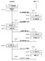
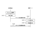
- FIG. 21 is a sequence diagram for referring to the advice list 92 using the user terminal 50.
- FIG. 21 when the user terminal 50 selects the "advice" button 61d of the main menu 61a (FIG. 10(b)) displayed on the browser of the user terminal 50 (S401), A request for the advice list screen 66 is made to the management server 30 (S402).
- the management server 30 Upon receiving the request for the advice list screen 66 from the user terminal 50, the management server 30 reads the data (S403), generates the advice list screen 66 (S404), and transmits it to the user terminal 50 (S405).
- the advice list screen 66 as shown in FIG. 22 is displayed on the browser of the user terminal 50 that has received the advice list screen 66 .
- the advice list screen 66 of this embodiment includes a search condition input section 66a for entering search conditions, a "new" button 66b for newly creating advice, and an advice list display section 66c for displaying an advice list 92 that matches the search conditions. , a "search” button 66d.
- any one of "No”, “Category”, “Date”, “Flag”, and “Alert” of the search condition input section 66a is set on the browser of the user terminal 50 (S406).
- an advice list 92 is requested from the management server 30 (S408).
- the management server 30 receives the request for the advice list 92 from the user terminal 50, reads the data (S409), generates the advice list 92 that matches the search conditions (S410), and transmits it to the user terminal 50 (S411). ).
- the advice list 92 as shown in FIG. 22 is displayed in the advice list display section 66c of the browser of the user terminal 50 that has received the advice list 92.
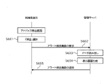
- FIG. 23 is a sequence diagram when using the user terminal 50 to inquire about specific advice. As shown in FIG. 23, when an arbitrary "inquiry" button in the advice list 92 displayed on the browser of the user terminal 50 is selected (S501), the user terminal 50 asks the management server 30 A request is made to display the advice inquiry screen 67 showing the details of the specified advice (S502).
- the management server 30 Upon receiving the request for the advice inquiry screen 67 from the user terminal 50, the management server 30 reads the data (S503), generates the advice inquiry screen 67 (S504), and transmits it to the user terminal 50 (S505).
- the browser of the user terminal 50 displays an advice inquiry screen 67 as shown in FIG.
- the advice inquiry screen 67 includes a basic information display portion 67a, an action item list 91, a seat surface heat map 81, a back surface heat map 82, a slip force map 83 (see FIGS. 14A and 14B), and a slip force graph 84.
- a seat pressure graph 85 and the basic information display section 67a includes a "No column”, a "period designation column”, a “category column”, a “flag column”, an "alert column”, and an “advice column”.
- FIG. 25 is a sequence diagram for inquiring the details of a specific alert from the advice inquiry screen 67 displayed on the browser of the user terminal 50.
- FIG. 25 As shown in FIG. 25, when the user terminal 50 selects the "inquiry” button next to the alert column on the browser of the user terminal 50 (S601), the alert specified for the management server 30 (S602).
- the management server 30 Upon receiving the request for the alert inquiry screen 70 from the user terminal 50, the management server 30 reads the data (S603), generates the alert inquiry screen 70 (S604), and transmits it to the user terminal 50 (S605).
- the browser of the user terminal 50 that has received the alert inquiry screen 70 displays the alert inquiry screen 70 as shown in FIG. 31(b). Details of the alert inquiry screen 70 will be described later.
- FIG. 26 is a sequence diagram when inquiring the details of a specific alert from the advice list screen 66 displayed on the browser of the user terminal 50.
- FIG. This process is the same as the process 8 described above.
- the user terminal 50 selects an arbitrary "reference" button from the alert details in the advice list 92 on the browser of the user terminal 50 (S701). , requests an alert inquiry screen 70 regarding the specified alert from the management server 30 (S702).
- the management server 30 Upon receiving the request for the alert inquiry screen 70 from the user terminal 50, the management server 30 reads the data (S703), generates the alert inquiry screen 70 (S704), and transmits it to the user terminal 50 (S705).
- the browser of the user terminal 50 that has received the alert inquiry screen 70 displays the alert inquiry screen 70 as shown in FIG. 31(b). Details of the alert inquiry screen 70 will be described later.
- FIG. 27 is a sequence diagram for deleting specific advice from the advice list screen 66 displayed on the user terminal 50. As shown in FIG. As shown in FIG. 27, when an arbitrary "delete" button is selected from the delete column of the advice list 92 displayed on the browser of the user terminal 50 (S711), the user terminal 50 30 is requested to delete the specified advice (S712).
- the management server 30 Upon receiving a request to delete advice from the user terminal 50, the management server 30 generates a pop-up deletion confirmation screen (not shown) (S713) and transmits it to the user terminal 50 (S714).
- the user terminal 50 When the user terminal 50 selects the "Confirm” button on the deletion confirmation screen popped up on the browser of the user terminal 50 (S715), the user terminal 50 requests the management server 30 to delete (confirm) the advice. (S716).
- the management server 30, which has received a request to delete (confirm) the advice from the user terminal 50, deletes the advice from the advice information storage unit 344 of the DB server 340 (S717), and generates a deletion completion screen (not shown) (S718). ), the generated deletion completion screen is transmitted to the user terminal 50 (S719).
- FIG. 28 is a sequence diagram when a physical therapist newly registers advice through the user terminal 50.
- the user terminal 50 selects the "New" button on the advice list screen 66 displayed on the browser of the user terminal 50 (S721), the user terminal 50 sends new advice to the management server 30.
- the input screen 68 is requested (S722).
- the management server 30 receives the request for the new advice input screen 68 from the user terminal 50, reads the data (S723), generates the new advice input screen 68 (S724), and transmits it to the user terminal 50 (S725). .
- the browser of the user terminal 50 displays the new advice input screen 68 as shown in FIG. 29(a).
- the new advice input screen 68 includes a condition setting section 68a, an advice input section 68b, a "determine” button 68c, a list display section 68d, a seat heat map 81, a back heat map 82, and a displacement force map 83 (not shown). ), a deviation force graph 84, and a seat pressure graph 85, and the condition setting section 68a includes a "period specification column”, a "category column”, a "flag column”, and an "alert column".
- the management server 30 When the user terminal 50 inputs conditions and advice on the new advice input screen 68 displayed on the browser of the user terminal 50 (S726) and selects the "OK" button 68c (S727), the management server 30 is requested to register new advice (S728).
- the management server 30 that has received the registration request for new advice from the user terminal 50 generates a registration confirmation screen 68e that pops up as shown in FIG. S730).
- the browser of the user terminal 50 pops up a registration confirmation screen 68e as shown in FIG. 29(b).
- the management server 30 receives a new advice registration (confirmation) request from the user terminal 50 and registers the advice in the advice information storage unit 344 of the DB server 340 (S733).
- the advice is transmitted (S735), and a registration completion screen (not shown) is generated (S734) and transmitted to the advice provider terminal 50 (S736).
- the advice is also sent to the SNS installed on the user terminal 50 (visible on the user terminal 50). This makes it easier for the wheelchair user to notice the problem and enables a quick response (action).
- the advice can also be sent by e-mail that can be viewed on the user terminal 50 .
- FIG. 30 is a sequence diagram for referring to the alert list 93 from the main screen 61 displayed on the user terminal 50.
- FIG. 30 when the user terminal 50 selects the "alert" button 61e of the main menu 61a (FIG. 10(b)) on the browser of the user terminal 50 (S801), the management server 30 is requested for the alert list screen 69 (S802).
- the management server 30 Upon receiving the request for the alert list screen 69 from the user terminal 50, the management server 30 reads the data (S803), generates the alert list screen 69 (S804), and transmits it to the user terminal 50 (S805).
- the browser of the user terminal 50 that has received the alert list screen 69 displays the alert list screen 69 as shown in FIG. 31(a).
- the alert list screen 69 of this embodiment includes a search condition input portion 69a for entering search conditions, an alert list display portion 69b for displaying an alert list 93 that matches the search conditions, and a "Search” button 69c.
- search condition input section 69a setting fields such as “No column”, “Category column”, “Date column”, and “Flag column” are displayed. field”, “category field”, “date field”, “flag field”, “alert content field”, and "related advice field”.
- the user terminal 50 selects any of the "No column”, “category column”, “date column”, “flag column”, and “alert column” of the search condition input section 69a on the alert list screen 69 displayed on the browser of the user terminal 50. is set (S806) and the "search” button 69c is selected (S807), the alert list 93 is requested from the management server 30 (S808).
- the management server 30 Upon receiving the request for the alert list 93 from the user terminal 50, the management server 30 reads the data (S809), generates the alert list 93 that matches the search conditions (S810), and transmits it to the user terminal 50 (S811 ).
- the alert list display section 69b of the browser of the user terminal 50 that has received the alert list 93 displays the alert list 93 as shown in FIG. 31(a).
- FIG. 32 is a sequence diagram when inquiring the details of a specific alert from the alert list screen 69 displayed on the user terminal 50.
- FIG. 32 when an arbitrary "query" button is selected from the alert list 93 on the browser of the user terminal 50 (S821), the user terminal 50 specifies to the management server 30 Requests the alert query screen 70 for the given alert (S822).
- the management server 30 Upon receiving the request for the alert inquiry screen 70 from the user terminal 50, the management server 30 reads the data (S823), generates the alert inquiry screen 70 (S824), and transmits it to the user terminal 50 (S825).
- the browser of the user terminal 50 that has received the alert inquiry screen 70 displays the alert inquiry screen 70 as shown in FIG. 31(b).
- the alert inquiry screen 70 of this embodiment includes a basic information display section 70a, an "advice input” button 70b, a “return” button 70c, a list display section 70d, a seat surface heat map 81, a back surface heat map 82, and a displacement force map 83. (not shown), a displacement force graph 84, and a seat pressure graph 85.
- the basic information display section 70a includes a "No column”, an "occurrence period column”, a “category column”, a “flag column”, an “alert column”, and an “advice column”.
- a "query” button is included.
- the user of the user terminal 50 can browse the content of the alert and various data (lists, maps, graphs, etc.) associated with the alert from the alert inquiry screen 70 .
- FIG. 33 is a sequence diagram for referring to advice related to the alert from the alert inquiry screen 70 displayed on the user terminal 50.
- FIG. 33 As shown in FIG. 33, on the user terminal 50, on the alert inquiry screen 70 (FIG. 31(b)) displayed on the browser of the user terminal 50, the "inquiry" button displayed on the right side of the advice column is When selected (S901), a request is made to the management server 30 for a related advice list (not shown) related to the alert (S902).
- the management server 30 receives the request for the related advice list from the user terminal 50, reads the data (S903), generates the related advice list (S904), and transmits it to the user terminal 50 (S905).
- a related advice list similar to the advice list 92 in FIG. 22 is displayed on the browser of the user terminal 50 that has received the related advice list.
- wheelchair users can receive alerts and advice in real time, so they can reduce the risk of pressure ulcers by changing their posture each time. Also, you can visually understand your own sedentary habits, posture deviations, etc. with a seat heat map 81, a back heat map 82, a deviation force map 83, a deviation force graph 84, a sitting pressure graph 85, a behavior graph 86, etc. This can be confirmed with an easy-to-use chart.
- the pressure ulcer prevention system of the present embodiment not only wheelchair users but also physical therapists, caregivers, family members, medical personnel, insurance personnel, etc. can use their own user terminals 50 to Since the provided information can be browsed and the information can be shared among related parties including the wheelchair user, appropriate support can be provided to the wheelchair user with a common understanding.
- the lists, maps, and graphs generated by the management server 30 of the above embodiment are examples, and the management server 30 can also create charts other than these.
- the seating device 10 can also be configured to include a cushion material placed on the seat surface X1.
- the cushion material may have a mechanism capable of partially changing the air pressure by sucking and discharging air.
- the air pressure is automatically adjusted according to the seat pressure detected by the sensor 14, and the pressure can be released without the wheelchair user performing the pressure release operation.
- the sensor sheet 13 to which the sensor 14 is attached is covered with the sheet cover 15 as an example of the sensor unit 11, but a thin film such as polyimide is used as the sensor sheet 13, and the thin film has a predetermined thickness. It is also possible to use a seat cover 15 made of urethane foam or the like on which a number of sensors 14 are mounted (single-sheet sensor). In this case, the connector and cord connected to the sensor 14 are also accommodated inside the urethane foam.
- the one-piece sensor is preferably constructed so as to have a thickness of about 3 to 5 mm.
- the thin film can have a thickness of 0.1 to 1.0 mm, preferably about 0.1 to 0.5 mm.
- a flexible printed circuit board (FPC) or the like can also be used, in which a conductive foil such as a copper foil is attached to a base film such as a polyimide thin film.
- Wheelchair X cushions may change shape depending on air pressure, contain gel-like material inside, have a honeycomb structure inside, be made of urethane foam, or have a surface There are various types such as those with unevenness.
- a woven sensor such as the one disclosed in Patent Document 1
- the seat pressure is increased. Accurate detection may not be possible.
- the sheet-shaped sensor unit 11 described above the seat surface sensor 14a does not fall between the unevenness of the cushion, and the seat pressure can be accurately detected.
- both the portion placed on the seat surface X1 and the portion placed in front of the backrest X2 may be collectively used as a single object sensor, or each of the two may be separately used as a single object sensor.
- the management server 30 stores a program (application program) for causing the management server 30 to execute each process described above or later (to cause the computer to function as a server that performs each process).
- this program can also be stored in a storage medium readable by the management server 30 .
- the computer here is a so-called electronic calculator, and is a broad concept that includes various types of electronic calculators such as smartphones and tablet terminals in addition to PCs.
- the sensor unit 11 having both the seat surface portion 11a and the back surface portion 11b is used as an example. ) can be omitted. Further, if only back pressure data can be acquired, the seat portion 11a (including the seat 13a and the seat cover 15a) can be omitted.
- the case where a physical therapist registers new advice is taken as an example, but doctors, nurses, caregivers, etc. can also register advice using the user terminal 50 they use. In this case as well, the management server 30 performs the same processing as when a physical therapist registers new advice.
- the case where all processing is performed in the management server 30 has been described as an example. can be configured to Also, the various processes shown in the above embodiment are examples, and the management server 30 may execute processes other than those described above. The various processes shown in the above embodiments can be executed by hardware as well as by software.
- the pressure ulcer prevention system can implement a function that measures the posture of the seated person from the position of the center of gravity and the back pressure. Specifically, from the relationship between the position of the center of gravity and the pressure of the seat surface X1 and the backrest X2, the center, left side, right side, left twist, right twist, left leg cross, right leg cross, left back leaning, right back leaning Posture prediction such as hanging can be performed. Wheelchair users and other users of the pressure ulcer prevention system can view posture information from their own user terminals 50 .
- the management server 30 When implementing the posture measurement function, the management server 30 performs the following processing. For example, when viewing posture information is requested from a posture information viewing page displayed on the user terminal 50, the management server 30 reads the data, generates a seated person posture screen, and displays the generated seated person posture screen. It is transmitted to the user terminal 50 concerned. On the seated person posture screen, posture labels such as center, left leaning, right leaning, left twist, right twist, left foot cross, right foot cross, left back leaning, right back leaning, etc. are displayed.
- Whether the posture of the seated person corresponds to midline, left side, right side, left twist, right twist, left leg cross, right leg cross, left back leaning, right back leaning, etc. can be determined by, for example, the following method. can do. That is, a plurality of conditions are set from combinations of seat pressure, back pressure, and center-of-gravity position data. , and the acquired data and the set conditions are compared, and the posture of the seated person can be determined depending on which condition the posture satisfies.
- the posture determination method shown here is just an example, and posture determination can also be performed by other methods.
- the attending physician and physical therapist of the wheelchair user can advise what points should be improved and what kind of exercise should be increased. be able to.
- the advice can be registered, for example, by the procedure shown in the process 11 (advice new registration process), and the wheelchair user refers to the advice list 92 in the procedure shown in the process 6 (advice list reference process), and performs the above process. Advice can be browsed by the procedure shown in 7 (advice inquiry processing).
- Training includes abdominal muscles, back muscles, side bends, rotations, and the like. It should be noted that a wheelchair user can perform various exercises such as sit-ups, back muscles, lateral bending, rotation, etc. on the wheelchair X.
- a necessary training pattern is set in the management server 30 in advance based on the sitting position and sitting pressure data, and training is performed by comparing the actually acquired data with the set training pattern sitting position and sitting pressure data. Identify patterns.
- a wheelchair user can browse the training pattern displayed on the user terminal 50 and perform the training.
- the management server 30 When implementing the training function, the management server 30 performs the following processing. For example, when viewing training information is requested from a training page displayed on the user terminal 50, the management server 30 reads the data, generates a training information screen, and displays the generated training information screen to the user terminal. Send to 50. The training information screen displays specific training content to be performed.
- a training mode it may be possible to set a training mode so that it can be determined from the movement of the center of gravity position whether or not the specified training has been completed. Based on the determination result, the responsible physical therapist or the like can determine whether or not the training is being carried out appropriately, and determine the content of subsequent training.
- the training function can also be used during remote rehabilitation.
- the pressure ulcer prevention system it is also possible to implement a function that allows viewing comparison information on the user terminal 50. For example, in addition to comparing one's own action history at any two points in time (daily, weekly, monthly, etc.), others of the same age as oneself, others living in the same area as oneself, and oneself and disability type It is possible to view comparison information with others who have common matters, such as the same others, others who have the same occupation as the user himself/herself. As comparison information, in addition to the average value for a certain period, information such as the maximum value and the minimum value for a certain period can be used.
- the management server 30 When implementing this function, the management server 30 performs the following processing. For example, when viewing comparison information is requested from a viewing page for comparison information displayed on the user terminal 50, the management server 30 reads the data, generates a comparison screen, and displays the generated comparison screen to the user. Send to terminal 50 . By browsing the comparison screen displayed on the user terminal 50, the wheelchair user can easily set his or her own life goal and action goal, and can lead to maintenance and improvement of motivation and behavioral change.
- comparison information can also be viewed on the user terminal 50 that the physical therapist in charge of remote rehabilitation uses when performing remote rehabilitation.
- a physical therapist in charge of remote rehabilitation can, for example, browse the behavior history information of the wheelchair user at any two points in time, thereby considering an accurate rehabilitation plan and proposing it to the wheelchair user.
- a function that scores daily activities and shows indicators as numerical values For example, a point conversion table in which points are set according to the time, number of times, etc., for riding time, seat pressure, deviation force, each action, etc., is registered in advance in the management server 30, and the actually acquired data is converted into the point conversion table. , and the score can be calculated and viewed on the user terminal 50 .
- the management server 30 When implementing this function, the management server 30 performs the following processing. For example, when viewing of the life score is requested from the life score browsing page displayed on the user terminal 50, the management server 30 reads the data, generates the life score screen, and uses the generated life score screen for the relevant use. to the user terminal 50. Browsing the life score screen displayed on the user terminal 50 makes it easier for the user to set his or her own life goals and action goals, and can lead to maintenance and improvement of motivation and behavioral change.
- the pressure ulcer prevention system it is possible to implement a function that calculates position information, movement speed, road surface conditions, etc., and allows the user terminal 50 to view this information.
- a GPS module (including a communication module having a GPS function, etc.) is installed in the seating device 10, and position information data can be acquired by the GPS module.
- position information data can be acquired by the GPS module.
- the management server 30 by combining information such as seat pressure, back pressure, center of gravity position, activeness, etc. with the acquired position information data, (e.g., whether or not the wheelchair X is in the wheelchair X), and the moving distance and moving speed of the wheelchair X can be calculated.
- the management server 30 from the acquired position information, movement speed, data of the seat surface X1 and the backrest X2, etc., the road surface conditions (slopes, rough roads, steps, etc.) and movement conditions (mobility It is also possible to measure the movement environment such as whether the robot is used or not, and the presence or absence of assistance.
- the management server 30 reads the data. to generate a life information screen, and transmit the generated life information screen to the user terminal 50 .
- the local government can build a smart wellness city that includes wheelchair users based on the life information. It can be expected that the life of the family, caregiver, etc. will be greatly improved.
- the pressure sensor (see FIGS. 3A and 3B), which is a kind of polymer thick film, is used as the sensor 14 as an example.
- the sensor 14 can use things.
- a pressure sensor configured using a conductive thread (hereinafter referred to as "conductive thread") 114 as shown in FIG. 34 can be used.
- two conductive threads 114 on the positive electrode side and the negative electrode side are spirally sewn on a resistance cloth 117 sewn on a base cloth 116 using a sewing thread 115 .
- Each conductive thread 114 is passed through a bobbin thread (not shown).
- the sewing shape of the conductive thread 114 is not limited to the spiral shape, and other shapes may be used.
- a portion of the base cloth 116 without the resistance cloth 117 becomes a conductor region, and one end of each conductive thread 114 spirally sewn to the resistance cloth 117 protrudes from the resistance cloth 117 and is sewn to the conductor region, An electrode 118 is formed.
- the control unit 12 is connected to the lower garment side garment 111 and the upper garment side garment 112 via electrodes 118 .
- polyamide conductive thread is used as the conductive thread 114
- polyester thread is used as the sewing thread 115
- felt cloth material is used as the base cloth 116
- carbon mesh cloth cloth material is used as the resistance cloth 117.
- the conductive thread 114, the sewing thread 115, the base cloth 116, and the resistance cloth 117 may be other materials.
- each of the areas where the two conductive threads 114 on the positive electrode side and the negative electrode side are sewn becomes a sensing area.
- the pressure applied to each sensor 14 can be specified as an absolute value.
- the sensing device 100 described here is just an example, and the sensing device 100 may be an installation device other than the above or a wearable device worn by a wheelchair user (hereinafter referred to as a “wearable device”).
- an installation type device (seating device 10) is used as the sensing device 100, but a wearable device can also be used as the sensing device 100.
- a sensor mounted on a lower garment or upper garment that can be worn by a wheelchair user as shown in FIGS. 35(a) and 35(b) can be used.
- a jacket is a piece of clothing worn on the upper body and corresponds to a so-called top.
- a lower garment is clothing worn on the lower half of the body, and corresponds to so-called bottoms.
- the wearable device shown in FIGS. 35(a) and 35(b) includes a lower garment side garment 111 worn on the lower body (FIG. 35(a)) and an upper garment side garment 112 worn on the upper body (FIG. 35(b)). )).
- the bottom garment 111 of this embodiment is shaped like long pants, and includes two leg coverings 111a for accommodating the wearer's legs, and a crotch upper covering for accommodating the base of the leg to the waist. 111b.
- the seat surface sensor 14a of the seating device 10 has a region (thigh region) on the back side of the thigh of both leg coverings 111a and a region of the back of the buttocks (buttocks region) of the upper crotch covering 111b.
- a corresponding sensor 113 (hereinafter referred to as a "bottom-side sensor 113a") is provided, and the area where the cloth material constituting the bottom-side garment 111 is present corresponds to the non-installation area 14c of the seating device 10.
- a non-installation area is provided.
- the number of the lower garment side sensors 113a is reduced as in the case of the seating device 10 described above. can be minimized, and as a result, the time for transmitting data to the management server 30 (external device) can be shortened, and a system capable of transmitting information to wheelchair users in real time can be constructed.
- portions other than the thigh region and the buttock region of the lower garment side garment 111 can also be treated as a non-installation region in which the sensor 113 is not provided. It also includes a space portion where the cloth material constituting the lower garment side garment 111 between the portions 111a does not exist.
- the outer garment 112 of this embodiment has a shape like a T-shirt, and includes a body portion 112a and both sleeve portions 112b.
- a sensor 113 corresponding to the back sensor 14b of the seating device 10 (hereinafter referred to as a "top-side sensor 113b") is provided on the back side (back area) of the body portion 112a.
- a pressure sensor which is a type of polymer thick film as shown in FIGS. A configured pressure sensor or the like can be used.
- the pressure sensors configured using the conductive thread 114 are used as the lower garment side sensor 113a and the upper garment side sensor 113b, the fabric material constituting the lower garment side garment 111 and the upper garment side garment 112 is used as the base cloth 116. be able to.
- the present invention is not limited to the structures and shapes of the above embodiments, and various modifications and changes are possible without departing from the spirit of the present invention.
- the present invention can also be applied to information processing systems other than the bedsore prevention system.
- the elements that make up the information processing system can have a configuration different from that of the pressure ulcer prevention system.
- the configuration of the management server 30 may be designed according to the information processing system to be constructed, and the functions implemented in the management server 30 can be distributed to a plurality of servers or integrated into a single server.
- the information processing system only needs to function as a whole, and which function is implemented in which device can be designed according to the information processing system to be constructed.
- the configuration of each screen displayed is an example, and the configuration of each screen may be different from that in the above-described embodiment.
- the sensing device 100 of the present invention can be used as a pressure ulcer prevention system for wheelchair users. It can also be used as a stiff shoulder prevention system.
Landscapes
- Health & Medical Sciences (AREA)
- Life Sciences & Earth Sciences (AREA)
- Animal Behavior & Ethology (AREA)
- General Health & Medical Sciences (AREA)
- Public Health (AREA)
- Veterinary Medicine (AREA)
- Force Measurement Appropriate To Specific Purposes (AREA)
- Chair Legs, Seat Parts, And Backrests (AREA)
- Measurement Of The Respiration, Hearing Ability, Form, And Blood Characteristics Of Living Organisms (AREA)
Priority Applications (2)
| Application Number | Priority Date | Filing Date | Title |
|---|---|---|---|
| JP2022514460A JP7182828B1 (ja) | 2021-03-03 | 2022-03-01 | センシングデバイス |
| JP2022182596A JP2023014126A (ja) | 2021-03-03 | 2022-11-15 | センシングデバイス |
Applications Claiming Priority (2)
| Application Number | Priority Date | Filing Date | Title |
|---|---|---|---|
| JP2021033690 | 2021-03-03 | ||
| JP2021-033690 | 2021-03-03 |
Publications (1)
| Publication Number | Publication Date |
|---|---|
| WO2022186171A1 true WO2022186171A1 (ja) | 2022-09-09 |
Family
ID=83154456
Family Applications (1)
| Application Number | Title | Priority Date | Filing Date |
|---|---|---|---|
| PCT/JP2022/008485 Ceased WO2022186171A1 (ja) | 2021-03-03 | 2022-03-01 | センシングデバイス |
Country Status (2)
| Country | Link |
|---|---|
| JP (2) | JP7182828B1 (https=) |
| WO (1) | WO2022186171A1 (https=) |
Cited By (1)
| Publication number | Priority date | Publication date | Assignee | Title |
|---|---|---|---|---|
| CN119745612A (zh) * | 2025-03-07 | 2025-04-04 | 深圳复成医疗科技有限公司 | 一种电动轮椅背靠调节方法、装置、电子设备及存储介质 |
Citations (6)
| Publication number | Priority date | Publication date | Assignee | Title |
|---|---|---|---|---|
| JP2012071098A (ja) * | 2010-08-31 | 2012-04-12 | Tokai Rubber Ind Ltd | シートおよび車椅子 |
| KR20170074045A (ko) * | 2015-12-21 | 2017-06-29 | 엘지이노텍 주식회사 | 압력 감지 의자 |
| JP2017121442A (ja) * | 2016-01-08 | 2017-07-13 | パナソニックIpマネジメント株式会社 | 生体信号検出装置および生体信号検出方法 |
| JP2018102861A (ja) * | 2016-12-28 | 2018-07-05 | 株式会社槌屋 | 座位姿勢モニタリングシステム |
| US20180345079A1 (en) * | 2017-06-02 | 2018-12-06 | Suunto Oy | Sensor module for personal performance monitoring and related arrangement and method |
| JP2020076586A (ja) * | 2018-11-05 | 2020-05-21 | 株式会社テクサー | 圧力センサシート |
Family Cites Families (2)
| Publication number | Priority date | Publication date | Assignee | Title |
|---|---|---|---|---|
| JP7022274B2 (ja) * | 2017-10-06 | 2022-02-18 | テイ・エス テック株式会社 | 着座センサ |
| JP7208485B2 (ja) * | 2018-11-29 | 2023-01-19 | テイ・エス テック株式会社 | シートシステム |
-
2022
- 2022-03-01 JP JP2022514460A patent/JP7182828B1/ja active Active
- 2022-03-01 WO PCT/JP2022/008485 patent/WO2022186171A1/ja not_active Ceased
- 2022-11-15 JP JP2022182596A patent/JP2023014126A/ja active Pending
Patent Citations (6)
| Publication number | Priority date | Publication date | Assignee | Title |
|---|---|---|---|---|
| JP2012071098A (ja) * | 2010-08-31 | 2012-04-12 | Tokai Rubber Ind Ltd | シートおよび車椅子 |
| KR20170074045A (ko) * | 2015-12-21 | 2017-06-29 | 엘지이노텍 주식회사 | 압력 감지 의자 |
| JP2017121442A (ja) * | 2016-01-08 | 2017-07-13 | パナソニックIpマネジメント株式会社 | 生体信号検出装置および生体信号検出方法 |
| JP2018102861A (ja) * | 2016-12-28 | 2018-07-05 | 株式会社槌屋 | 座位姿勢モニタリングシステム |
| US20180345079A1 (en) * | 2017-06-02 | 2018-12-06 | Suunto Oy | Sensor module for personal performance monitoring and related arrangement and method |
| JP2020076586A (ja) * | 2018-11-05 | 2020-05-21 | 株式会社テクサー | 圧力センサシート |
Cited By (1)
| Publication number | Priority date | Publication date | Assignee | Title |
|---|---|---|---|---|
| CN119745612A (zh) * | 2025-03-07 | 2025-04-04 | 深圳复成医疗科技有限公司 | 一种电动轮椅背靠调节方法、装置、电子设备及存储介质 |
Also Published As
| Publication number | Publication date |
|---|---|
| JP2023014126A (ja) | 2023-01-26 |
| JPWO2022186171A1 (https=) | 2022-09-09 |
| JP7182828B1 (ja) | 2022-12-05 |
Similar Documents
| Publication | Publication Date | Title |
|---|---|---|
| Anwary et al. | Smart-Cover: A real time sitting posture monitoring system | |
| JP3098997B1 (ja) | 介護支援装置 | |
| Abou et al. | Sensitivity of Apple Watch fall detection feature among wheelchair users | |
| CN111195180A (zh) | 用于确定目标压力损伤评分并基于其更改治疗计划的系统和方法 | |
| JPWO2004114184A1 (ja) | ヘルスケア装置、生体情報端末 | |
| JP7182828B1 (ja) | センシングデバイス | |
| JP7338920B2 (ja) | 情報提供システム、管理サーバ、プログラム、記憶媒体 | |
| JP2004097495A (ja) | 睡眠状態判定装置及び就寝モニタリングシステム | |
| JP7044073B2 (ja) | 支援制御方法及び支援システム | |
| JP7581017B2 (ja) | 遠隔見守りシステム | |
| JP2022135996A (ja) | 健康支援方法、健康支援システム、プログラム、記憶媒体 | |
| Tamrat et al. | Operationalizing a wireless wearable fall detection sensor for older adults | |
| Barone et al. | Sensory garments with vibrotactile feedback for monitoring and informing seated posture | |
| Lin et al. | Development of home-based frailty detection device using wireless sensor networks | |
| Wong et al. | The feasibility of repositioning ability as a tool for ergonomic evaluation: effects of chair back inclination and fatigue on head repositioning | |
| Cummings | Health smart homes: User perspectives | |
| Han et al. | Towards detecting and predicting fall events in elderly care using bidirectional electromyographic sensor network | |
| CN115274107B (zh) | 一种智慧医疗联网跟踪的便携式健康状态预警系统 | |
| JP3994773B2 (ja) | 在宅者健康状態遠隔診断装置 | |
| Sundaram et al. | Classification of wheelchair pressure relief maneuvers using changes in center of pressure and weight on the seat | |
| CN206534798U (zh) | 一种多功能护理床 | |
| JP7320241B2 (ja) | 情報処理装置、褥瘡リスク評価方法及び褥瘡リスク評価プログラム | |
| JP2009199565A (ja) | 臥床要介護者の遠隔見守り方法ならびに臥床要介護者の遠隔見守り装置 | |
| KR20100125880A (ko) | 체형교정을 위한 의자 | |
| JP7800742B2 (ja) | 排尿量計測装置 |
Legal Events
| Date | Code | Title | Description |
|---|---|---|---|
| ENP | Entry into the national phase |
Ref document number: 2022514460 Country of ref document: JP Kind code of ref document: A |
|
| 121 | Ep: the epo has been informed by wipo that ep was designated in this application |
Ref document number: 22763226 Country of ref document: EP Kind code of ref document: A1 |
|
| NENP | Non-entry into the national phase |
Ref country code: DE |
|
| 122 | Ep: pct application non-entry in european phase |
Ref document number: 22763226 Country of ref document: EP Kind code of ref document: A1 |