WO2022185652A1 - 鉄道車両用駆動システムおよび鉄道車両用駆動方法 - Google Patents
鉄道車両用駆動システムおよび鉄道車両用駆動方法 Download PDFInfo
- Publication number
- WO2022185652A1 WO2022185652A1 PCT/JP2021/045950 JP2021045950W WO2022185652A1 WO 2022185652 A1 WO2022185652 A1 WO 2022185652A1 JP 2021045950 W JP2021045950 W JP 2021045950W WO 2022185652 A1 WO2022185652 A1 WO 2022185652A1
- Authority
- WO
- WIPO (PCT)
- Prior art keywords
- main circuit
- power
- railway vehicle
- stage
- vehicle drive
- Prior art date
- Legal status (The legal status is an assumption and is not a legal conclusion. Google has not performed a legal analysis and makes no representation as to the accuracy of the status listed.)
- Ceased
Links
Images




Classifications
-
- B—PERFORMING OPERATIONS; TRANSPORTING
- B60—VEHICLES IN GENERAL
- B60K—ARRANGEMENT OR MOUNTING OF PROPULSION UNITS OR OF TRANSMISSIONS IN VEHICLES; ARRANGEMENT OR MOUNTING OF PLURAL DIVERSE PRIME-MOVERS IN VEHICLES; AUXILIARY DRIVES FOR VEHICLES; INSTRUMENTATION OR DASHBOARDS FOR VEHICLES; ARRANGEMENTS IN CONNECTION WITH COOLING, AIR INTAKE, GAS EXHAUST OR FUEL SUPPLY OF PROPULSION UNITS IN VEHICLES
- B60K6/00—Arrangement or mounting of plural diverse prime-movers for mutual or common propulsion, e.g. hybrid propulsion systems comprising electric motors and internal combustion engines
- B60K6/20—Arrangement or mounting of plural diverse prime-movers for mutual or common propulsion, e.g. hybrid propulsion systems comprising electric motors and internal combustion engines the prime-movers consisting of electric motors and internal combustion engines, e.g. HEVs
- B60K6/22—Arrangement or mounting of plural diverse prime-movers for mutual or common propulsion, e.g. hybrid propulsion systems comprising electric motors and internal combustion engines the prime-movers consisting of electric motors and internal combustion engines, e.g. HEVs characterised by apparatus, components or means specially adapted for HEVs
-
- B—PERFORMING OPERATIONS; TRANSPORTING
- B60—VEHICLES IN GENERAL
- B60K—ARRANGEMENT OR MOUNTING OF PROPULSION UNITS OR OF TRANSMISSIONS IN VEHICLES; ARRANGEMENT OR MOUNTING OF PLURAL DIVERSE PRIME-MOVERS IN VEHICLES; AUXILIARY DRIVES FOR VEHICLES; INSTRUMENTATION OR DASHBOARDS FOR VEHICLES; ARRANGEMENTS IN CONNECTION WITH COOLING, AIR INTAKE, GAS EXHAUST OR FUEL SUPPLY OF PROPULSION UNITS IN VEHICLES
- B60K6/00—Arrangement or mounting of plural diverse prime-movers for mutual or common propulsion, e.g. hybrid propulsion systems comprising electric motors and internal combustion engines
- B60K6/20—Arrangement or mounting of plural diverse prime-movers for mutual or common propulsion, e.g. hybrid propulsion systems comprising electric motors and internal combustion engines the prime-movers consisting of electric motors and internal combustion engines, e.g. HEVs
- B60K6/42—Arrangement or mounting of plural diverse prime-movers for mutual or common propulsion, e.g. hybrid propulsion systems comprising electric motors and internal combustion engines the prime-movers consisting of electric motors and internal combustion engines, e.g. HEVs characterised by the architecture of the hybrid electric vehicle
- B60K6/46—Series type
-
- B—PERFORMING OPERATIONS; TRANSPORTING
- B60—VEHICLES IN GENERAL
- B60L—PROPULSION OF ELECTRICALLY-PROPELLED VEHICLES; SUPPLYING ELECTRIC POWER FOR AUXILIARY EQUIPMENT OF ELECTRICALLY-PROPELLED VEHICLES; ELECTRODYNAMIC BRAKE SYSTEMS FOR VEHICLES IN GENERAL; MAGNETIC SUSPENSION OR LEVITATION FOR VEHICLES; MONITORING OPERATING VARIABLES OF ELECTRICALLY-PROPELLED VEHICLES; ELECTRIC SAFETY DEVICES FOR ELECTRICALLY-PROPELLED VEHICLES
- B60L50/00—Electric propulsion with power supplied within the vehicle
- B60L50/50—Electric propulsion with power supplied within the vehicle using propulsion power supplied by batteries or fuel cells
- B60L50/60—Electric propulsion with power supplied within the vehicle using propulsion power supplied by batteries or fuel cells using power supplied by batteries
- B60L50/61—Electric propulsion with power supplied within the vehicle using propulsion power supplied by batteries or fuel cells using power supplied by batteries by batteries charged by engine-driven generators, e.g. series hybrid electric vehicles
-
- B—PERFORMING OPERATIONS; TRANSPORTING
- B60—VEHICLES IN GENERAL
- B60L—PROPULSION OF ELECTRICALLY-PROPELLED VEHICLES; SUPPLYING ELECTRIC POWER FOR AUXILIARY EQUIPMENT OF ELECTRICALLY-PROPELLED VEHICLES; ELECTRODYNAMIC BRAKE SYSTEMS FOR VEHICLES IN GENERAL; MAGNETIC SUSPENSION OR LEVITATION FOR VEHICLES; MONITORING OPERATING VARIABLES OF ELECTRICALLY-PROPELLED VEHICLES; ELECTRIC SAFETY DEVICES FOR ELECTRICALLY-PROPELLED VEHICLES
- B60L58/00—Methods or circuit arrangements for monitoring or controlling batteries or fuel cells, specially adapted for electric vehicles
- B60L58/10—Methods or circuit arrangements for monitoring or controlling batteries or fuel cells, specially adapted for electric vehicles for monitoring or controlling batteries
- B60L58/12—Methods or circuit arrangements for monitoring or controlling batteries or fuel cells, specially adapted for electric vehicles for monitoring or controlling batteries responding to state of charge [SoC]
-
- B—PERFORMING OPERATIONS; TRANSPORTING
- B60—VEHICLES IN GENERAL
- B60L—PROPULSION OF ELECTRICALLY-PROPELLED VEHICLES; SUPPLYING ELECTRIC POWER FOR AUXILIARY EQUIPMENT OF ELECTRICALLY-PROPELLED VEHICLES; ELECTRODYNAMIC BRAKE SYSTEMS FOR VEHICLES IN GENERAL; MAGNETIC SUSPENSION OR LEVITATION FOR VEHICLES; MONITORING OPERATING VARIABLES OF ELECTRICALLY-PROPELLED VEHICLES; ELECTRIC SAFETY DEVICES FOR ELECTRICALLY-PROPELLED VEHICLES
- B60L58/00—Methods or circuit arrangements for monitoring or controlling batteries or fuel cells, specially adapted for electric vehicles
- B60L58/10—Methods or circuit arrangements for monitoring or controlling batteries or fuel cells, specially adapted for electric vehicles for monitoring or controlling batteries
- B60L58/18—Methods or circuit arrangements for monitoring or controlling batteries or fuel cells, specially adapted for electric vehicles for monitoring or controlling batteries of two or more battery modules
-
- B—PERFORMING OPERATIONS; TRANSPORTING
- B60—VEHICLES IN GENERAL
- B60L—PROPULSION OF ELECTRICALLY-PROPELLED VEHICLES; SUPPLYING ELECTRIC POWER FOR AUXILIARY EQUIPMENT OF ELECTRICALLY-PROPELLED VEHICLES; ELECTRODYNAMIC BRAKE SYSTEMS FOR VEHICLES IN GENERAL; MAGNETIC SUSPENSION OR LEVITATION FOR VEHICLES; MONITORING OPERATING VARIABLES OF ELECTRICALLY-PROPELLED VEHICLES; ELECTRIC SAFETY DEVICES FOR ELECTRICALLY-PROPELLED VEHICLES
- B60L9/00—Electric propulsion with power supply external to the vehicle
- B60L9/16—Electric propulsion with power supply external to the vehicle using AC induction motors
- B60L9/18—Electric propulsion with power supply external to the vehicle using AC induction motors fed from DC supply lines
-
- B—PERFORMING OPERATIONS; TRANSPORTING
- B60—VEHICLES IN GENERAL
- B60W—CONJOINT CONTROL OF VEHICLE SUB-UNITS OF DIFFERENT TYPE OR DIFFERENT FUNCTION; CONTROL SYSTEMS SPECIALLY ADAPTED FOR HYBRID VEHICLES; ROAD VEHICLE DRIVE CONTROL SYSTEMS FOR PURPOSES NOT RELATED TO THE CONTROL OF A PARTICULAR SUB-UNIT
- B60W20/00—Control systems specially adapted for hybrid vehicles
-
- H—ELECTRICITY
- H02—GENERATION; CONVERSION OR DISTRIBUTION OF ELECTRIC POWER
- H02J—ELECTRIC POWER NETWORKS; CIRCUIT ARRANGEMENTS OR SYSTEMS FOR SUPPLYING OR DISTRIBUTING ELECTRIC POWER; SYSTEMS FOR STORING ELECTRIC ENERGY
- H02J7/00—Circuit arrangements for charging or discharging batteries or for supplying loads from batteries
-
- H—ELECTRICITY
- H02—GENERATION; CONVERSION OR DISTRIBUTION OF ELECTRIC POWER
- H02P—CONTROL OR REGULATION OF ELECTRIC MOTORS, ELECTRIC GENERATORS OR DYNAMO-ELECTRIC CONVERTERS; CONTROLLING TRANSFORMERS, REACTORS OR CHOKE COILS
- H02P27/00—Arrangements or methods for the control of AC motors characterised by the kind of supply voltage
- H02P27/04—Arrangements or methods for the control of AC motors characterised by the kind of supply voltage using variable-frequency supply voltage, e.g. inverter or converter supply voltage
- H02P27/06—Arrangements or methods for the control of AC motors characterised by the kind of supply voltage using variable-frequency supply voltage, e.g. inverter or converter supply voltage using DC to AC converters or inverters
-
- H—ELECTRICITY
- H02—GENERATION; CONVERSION OR DISTRIBUTION OF ELECTRIC POWER
- H02P—CONTROL OR REGULATION OF ELECTRIC MOTORS, ELECTRIC GENERATORS OR DYNAMO-ELECTRIC CONVERTERS; CONTROLLING TRANSFORMERS, REACTORS OR CHOKE COILS
- H02P5/00—Arrangements specially adapted for regulating or controlling the speed or torque of two or more electric motors
- H02P5/74—Arrangements specially adapted for regulating or controlling the speed or torque of two or more electric motors controlling two or more AC dynamo-electric motors
Definitions
- the present invention relates to a railway vehicle drive system and a railway vehicle drive method that are applied to a hybrid railway vehicle.
- a hybrid railway vehicle stores regenerative energy generated during braking in a battery, and discharges the battery during power running to supplement driving force and auxiliary loads, thereby reusing regenerative energy and converting it into energy.
- Patent Document 1 in a hybrid railway vehicle, a generator that is driven by an engine and generates AC power, a converter that converts the generated AC power to DC power, and a motor for driving the wheels that converts the DC power
- a railway vehicle drive system includes an inverter that converts the supplied AC power, a battery that charges and discharges the DC power, and a service power supply inverter that supplies AC power to auxiliary equipment such as air conditioners and lighting equipment.
- the railway vehicle drive system described in Patent Document 1 has one engine corresponding to the inverter mounted on each vehicle.
- it is necessary to run all the engines, and even in situations where the power is not required to move the train in the premises or the garage, all the engines can be operated. There is no change in the way the is moved.
- the object of the present invention is not only to drive all the power supply devices represented by the engine generator, fuel cell, storage battery, etc. during normal driving, but also to move a little within the premises or garage.
- a railway vehicle drive system capable of reducing the amount of power supplied from a power supply device (the amount of fuel consumed by an engine or a fuel cell, or the amount of discharge from a storage battery, etc.) under conditions where such power is not required.
- a typical railway vehicle drive system changes the voltage or frequency of power supplied from a power supply device to output DC power to a DC stage.
- an inverter for converting the DC power on the DC stage into AC power for driving the AC motor; and a power storage device for charging and discharging the DC power on the DC stage.
- a circuit system and a switch connecting the DC stage of the first main circuit system and the DC stage of the second main circuit system, the switch being opened to open the first and second main circuit systems respectively.
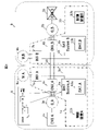
- FIG. 1 is a diagram showing a schematic configuration of a railroad vehicle equipped with a railroad vehicle drive system according to an embodiment of the present invention
- FIG. FIG. 10 is a diagram showing how the DC stage is controlled in the independent drive mode
- FIG. 10 is a diagram showing a control mode of the DC stage in the connection drive mode
- FIG. 10 is a diagram showing a current control mode of the power storage device 6b in the connection drive mode
- FIG. 3 is a diagram showing a method of transmitting SOC information of a storage battery 13a to a main circuit system 1b side;
- FIG. 1 is a diagram showing a schematic configuration of a railway vehicle equipped with a railway vehicle drive system according to an embodiment of the present invention.
- the railway vehicle drive system according to the embodiment is a hybrid system.
- the hybrid system here typically uses at least one of the power supplied by the generator driven by the engine mounted on the vehicle and the power supplied by the storage battery. It means a configuration that drives an electric motor or the like that is used.
- the main circuit system 1a includes, as a drive system for the first vehicle A, a converter 4a connected to a generator 3a driven by an engine 2a mounted on the first vehicle A, a DC stage 5a, a power storage device 6a, It is composed of an inverter 7a connected to a vehicle-driving induction motor 8a mounted on a first vehicle A and a control device 12a. Also, the DC stages 5a and 5b of the main circuit systems 1a and 1b are connected via a switch 9. FIG.
- the engine 2a is a diesel engine, is connected to the generator 3a, and drives the generator 3a.
- the engine is not limited to a diesel engine, and may be an internal combustion engine such as a gasoline engine.
- the generator 3a is an induction generator that drives the engine 2a to generate AC power and output it to the converter 4a.
- the generator driven by the engine is a typical power supply device, but instead of this, a DC power supply such as a fuel cell or a storage battery that generates DC power, or a power collection from DC or AC overhead wires
- the device may be a power supply.
- the converter 4a converts the AC power input from the generator 3a after the engine 2a is started into DC power, and outputs the DC power to the DC stage 5a (the same applies when using a current collector from the AC overhead wire).
- a DC power source such as a fuel cell or a storage battery that generates DC power or a current collector from a DC overhead wire is used instead of the engine 2a and the generator 3a
- the converter 4a is used to convert the voltage of the DC power. It consists of a DC/DC converter.
- the DC stage 5a is connected to the generator 3a, the power storage device 6a, and the inverter 7a. In addition, when the switch 9 is closed, the DC stage 5b of the main circuit system 1b is also connected.
- the power storage device 6a has a storage battery 13a inside and is connected to the converter 4a and the inverter 7a via the DC stage 5a.
- the power storage device 6a also has a function of controlling charging and discharging of the internal storage battery 13a, and for this purpose, for example, includes a DC/DC chopper (indicated by a dotted frame in FIG. 1). This DC/DC chopper controls charging and discharging between the DC stage 5a and the storage battery 13a.
- the storage battery 13a is a storage battery that charges and discharges DC power with the DC stage 5a.
- the storage battery 13a may have a plurality of series units in which a plurality of secondary batteries are connected in series, and the plurality of series units may be connected in parallel.
- a secondary battery for example, a lithium ion storage battery can be used.
- the inverter 7a is connected to the converter 4a and the power storage device 6a via a DC stage 5a, and is additionally connected to the DC stage 5b of the main circuit system 1b when the switch 9 is closed. On the other hand, it is connected to the induction motor 8a. After the engine 2a is started, the inverter 7a converts DC power input from at least one of the converter 4a and the power storage device 6a into AC power, and outputs the AC power to the induction motor 8a.
- the induction motor 8a is connected to the inverter 7a, and during power running, drives the wheels of the railway vehicle by converting the AC power input from the inverter 7a into shaft torque of the wheels of the railway vehicle. Further, during regenerative operation, the induction motor 8a functions as a generator.
- the switch 9 is a switch for connecting the respective DC stages 5a and 5b of the main circuit systems 1a and 1b.
- the switch 9 When the switch 9 is closed, the DC stages 5a and 5b of the main circuit systems 1a and 1b are connected.
- the switch 9 when the switch 9 is opened, the DC stages 5a and 5b of the main circuit systems 1a and 1b are not connected, and the main circuit systems 1a and 1b operate independently.
- the operation mode when the switch 9 is opened by opening and closing the switch 9 is called “independent drive mode", and the operation mode when the switch 9 is closed is called “connected drive mode”. can be switched.
- the control device 12a controls, for example, the engine 2a, the generator 3a, the converter 4a, the power storage device 6a, and the inverter 7a.
- the controller 12a controls these components, but the controllers 12a and 12b may be individually provided for each main circuit system, or the main circuit systems 1a and 1b may be used as one controller. may be provided.
- FIG. 2 is a diagram showing how the DC stage is controlled in the independent drive mode.
- the independent drive mode since the switch 9 is open, the DC stages 5a and 5b of the main circuit systems 1a and 1b are not connected, so that the voltage of the DC stage 5a is the output power from the converter 4a and the power storage device 6a. and the input/output power from the inverter 7a.
- the converter 4a performs current control, and the power storage device 6a performs voltage control based on the difference between the target voltage and the voltage of the DC stage 5a.
- the converter 4a performs voltage control based on the difference between the target voltage and the voltage of the DC stage 5a, and the power storage device 6a performs current control, thereby maintaining the target voltage of the inverter 7a at 3000V. Control modes are also conceivable.
- FIG. 3 is a diagram showing how the DC stage is controlled in the connection drive mode.
- FIG. 3 shows a case where the engine 2b is stopped and the inverters 7a and 7b are driven by the engine 2a and the power storage devices 6a and 6b. Conversely, there is also a case where the engine 2a is stopped and the inverters 7a and 7b are driven by the engine 2b and the power storage devices 6a and 6b.
- the connection drive mode since the switch 9 is closed, the DC stages 5a and 5b of the main circuit systems 1a and 1b are connected, so that the two DC stages 5a and 5b have the same potential.
- the DC stage when the switch 9 is closed is referred to as a DC stage 10 as shown in FIG.
- converters 4a and 4b, power storage devices 6a and 6b, and inverters 7a and 7b are connected to DC stage 10, but since engine 2b is stopped, converter 4b No power is output from That is, the voltage of DC stage 10 is determined by the output power of converter 4a, the input/output power of power storage device 6a, the input/output power of power storage device 6b, the input/output power of inverter 7a, and the input/output power of inverter 7b.
- the converter 4a performs current control
- the power storage device 6a performs voltage control of the DC stage from the difference between the target voltage and the DC stage 10 voltage.
- the power storage device 6b performs current control.
- FIG. 4 is a diagram showing a current control mode of the power storage device 6b in the connection drive mode.
- the input/output power of the power storage device 6b is determined by the difference in SOC (State Of Charge) between the storage battery 13a of the power storage device 6a and the storage battery 13b of the power storage device 6b.
- SOC State Of Charge
- each voltage of the storage batteries 13a and 13b (that is, the voltage difference between them), each input/output voltage of the power storage devices 6a and 6b (that is, the input/output voltage difference between them) ), may be controlled by
- FIG. 5 is a diagram showing a method of transmitting the SOC information of the storage battery 13a to the main circuit system 1b side.
- the main circuit systems 1a and 1b have information transmission devices 11a and 11b, respectively, and mutually transmit the SOC information of the storage batteries 13a and 13b to share the respective SOC information.
- the information transmission devices 11a and 11b are provided in the main circuit systems 1a and 1b respectively, but the number of information transmission devices may be integrated into one.
- the information to be transmitted may be the voltages of the storage batteries 13a and 13b and the input/output voltages of the power storage devices 6a and 6b instead of the SOC information.
- the present invention can also be applied to a train set of three or more cars.
- the main circuit system corresponding to the engine to be stopped and the main circuit system corresponding to the engine to be driven mutually share the SOC information of each power storage device, and the voltage of the DC stage control and current control.
- a railway vehicle drive system capable of reducing fuel consumption by switching operation modes in situations where power is not required, such as small movements within a premises or a garage, is provided. realizable.
- 1a, 1b main circuit system
- 2a, 2b engine
- 3a, 3b generator
- 4a, 4b converter
- 5a, 5b, 10 DC stage
- 6a, 6b power storage device
- 7a, 7b inverter
- 8a, 8b induction motor
- 9 switch
- 11a, 11b information transmission device
- 12a, 12b control device
- 13a, 13b storage battery
- B second vehicle
Landscapes
- Engineering & Computer Science (AREA)
- Power Engineering (AREA)
- Transportation (AREA)
- Mechanical Engineering (AREA)
- Life Sciences & Earth Sciences (AREA)
- Sustainable Development (AREA)
- Sustainable Energy (AREA)
- Chemical & Material Sciences (AREA)
- Combustion & Propulsion (AREA)
- Automation & Control Theory (AREA)
- Electric Propulsion And Braking For Vehicles (AREA)
- Hybrid Electric Vehicles (AREA)
Priority Applications (1)
| Application Number | Priority Date | Filing Date | Title |
|---|---|---|---|
| JP2023503389A JP7480416B2 (ja) | 2021-03-02 | 2021-12-14 | 鉄道車両用駆動システムおよび鉄道車両用駆動方法 |
Applications Claiming Priority (2)
| Application Number | Priority Date | Filing Date | Title |
|---|---|---|---|
| JP2021032676 | 2021-03-02 | ||
| JP2021-032676 | 2021-03-02 |
Publications (1)
| Publication Number | Publication Date |
|---|---|
| WO2022185652A1 true WO2022185652A1 (ja) | 2022-09-09 |
Family
ID=83154264
Family Applications (1)
| Application Number | Title | Priority Date | Filing Date |
|---|---|---|---|
| PCT/JP2021/045950 Ceased WO2022185652A1 (ja) | 2021-03-02 | 2021-12-14 | 鉄道車両用駆動システムおよび鉄道車両用駆動方法 |
Country Status (2)
| Country | Link |
|---|---|
| JP (1) | JP7480416B2 (https=) |
| WO (1) | WO2022185652A1 (https=) |
Cited By (2)
| Publication number | Priority date | Publication date | Assignee | Title |
|---|---|---|---|---|
| WO2025203262A1 (ja) * | 2024-03-26 | 2025-10-02 | 三菱電機株式会社 | 駆動制御装置 |
| WO2026033929A1 (ja) * | 2024-08-09 | 2026-02-12 | 株式会社日立製作所 | 車上装置、鉄道車両および蓄電池の充放電方法 |
Citations (3)
| Publication number | Priority date | Publication date | Assignee | Title |
|---|---|---|---|---|
| JP2008131834A (ja) * | 2006-11-24 | 2008-06-05 | Hitachi Ltd | 鉄道車両の駆動制御装置 |
| WO2014041695A1 (ja) * | 2012-09-14 | 2014-03-20 | 三菱電機株式会社 | ハイブリッド車両の推進制御装置 |
| JP2019122122A (ja) * | 2017-12-28 | 2019-07-22 | 株式会社日立製作所 | 鉄道車両に備えられた蓄電装置の充放電を制御する制御装置及び制御方法 |
-
2021
- 2021-12-14 WO PCT/JP2021/045950 patent/WO2022185652A1/ja not_active Ceased
- 2021-12-14 JP JP2023503389A patent/JP7480416B2/ja active Active
Patent Citations (3)
| Publication number | Priority date | Publication date | Assignee | Title |
|---|---|---|---|---|
| JP2008131834A (ja) * | 2006-11-24 | 2008-06-05 | Hitachi Ltd | 鉄道車両の駆動制御装置 |
| WO2014041695A1 (ja) * | 2012-09-14 | 2014-03-20 | 三菱電機株式会社 | ハイブリッド車両の推進制御装置 |
| JP2019122122A (ja) * | 2017-12-28 | 2019-07-22 | 株式会社日立製作所 | 鉄道車両に備えられた蓄電装置の充放電を制御する制御装置及び制御方法 |
Cited By (2)
| Publication number | Priority date | Publication date | Assignee | Title |
|---|---|---|---|---|
| WO2025203262A1 (ja) * | 2024-03-26 | 2025-10-02 | 三菱電機株式会社 | 駆動制御装置 |
| WO2026033929A1 (ja) * | 2024-08-09 | 2026-02-12 | 株式会社日立製作所 | 車上装置、鉄道車両および蓄電池の充放電方法 |
Also Published As
| Publication number | Publication date |
|---|---|
| JPWO2022185652A1 (https=) | 2022-09-09 |
| JP7480416B2 (ja) | 2024-05-09 |
Similar Documents
| Publication | Publication Date | Title |
|---|---|---|
| US11351874B2 (en) | Vehicle propulsion system with multi-channel DC bus and method of manufacturing same | |
| AU2010257243B2 (en) | Energy storage system and method for hybrid propulsion | |
| EP1925493A2 (en) | Energy management for hybrid energy railway vehicle | |
| JP6907175B2 (ja) | 電源システム | |
| IT202000002566A1 (it) | Veicolo a trazione elettrica includente un sistema di gestione di energia, e metodo di gestione di energia in tale veicolo a trazione elettrica | |
| CN102602301B (zh) | 一种用于燃料电池混合动力车辆的电气系统 | |
| KR20180127600A (ko) | 차량용 배터리 충전 제어시스템 | |
| US20200376949A1 (en) | Vehicle drive system | |
| JP7480416B2 (ja) | 鉄道車両用駆動システムおよび鉄道車両用駆動方法 | |
| CN201833893U (zh) | 用于地铁调车的电传动系统 | |
| US10131366B2 (en) | Hybrid vehicle power generation control apparatus | |
| JPWO2022185652A5 (https=) | ||
| KR100911537B1 (ko) | 고전압 배터리의 충전제어장치 | |
| US20150225000A1 (en) | Propulsion control device of hybrid vehicle | |
| CN119773470A (zh) | 用于移动式起重机的驱动设备 | |
| KR20110048857A (ko) | 전기자동차 | |
| JP4329454B2 (ja) | 電気自動車システム | |
| US11999241B2 (en) | Hybrid system to overhaul a DC locomotive | |
| JP2004336833A (ja) | 鉄道車両用電力変換器の制御装置 | |
| JP7614784B2 (ja) | 車両駆動装置 | |
| CN118545099A (zh) | 一种牵引系统 | |
| EP3960522A1 (en) | Vehicle energy storage | |
| SK289230B6 (sk) | Modifikované zapojenie striedavého prenosu výkonu hybridného elektrického vozidla |
Legal Events
| Date | Code | Title | Description |
|---|---|---|---|
| 121 | Ep: the epo has been informed by wipo that ep was designated in this application |
Ref document number: 21929210 Country of ref document: EP Kind code of ref document: A1 |
|
| DPE1 | Request for preliminary examination filed after expiration of 19th month from priority date (pct application filed from 20040101) | ||
| ENP | Entry into the national phase |
Ref document number: 2023503389 Country of ref document: JP Kind code of ref document: A |
|
| NENP | Non-entry into the national phase |
Ref country code: DE |
|
| 122 | Ep: pct application non-entry in european phase |
Ref document number: 21929210 Country of ref document: EP Kind code of ref document: A1 |