WO2022185421A1 - 通信装置及び通信方法 - Google Patents
通信装置及び通信方法 Download PDFInfo
- Publication number
- WO2022185421A1 WO2022185421A1 PCT/JP2021/008022 JP2021008022W WO2022185421A1 WO 2022185421 A1 WO2022185421 A1 WO 2022185421A1 JP 2021008022 W JP2021008022 W JP 2021008022W WO 2022185421 A1 WO2022185421 A1 WO 2022185421A1
- Authority
- WO
- WIPO (PCT)
- Prior art keywords
- data
- transmission
- resource
- signal
- communication device
- Prior art date
Links
- 238000004891 communication Methods 0.000 title claims abstract description 97
- 238000000034 method Methods 0.000 title claims description 52
- 230000005540 biological transmission Effects 0.000 claims abstract description 202
- 238000010586 diagram Methods 0.000 description 35
- 238000001514 detection method Methods 0.000 description 26
- 230000006870 function Effects 0.000 description 12
- 238000012545 processing Methods 0.000 description 11
- 230000008054 signal transmission Effects 0.000 description 9
- 230000011664 signaling Effects 0.000 description 8
- 238000005516 engineering process Methods 0.000 description 7
- 230000002776 aggregation Effects 0.000 description 5
- 238000004220 aggregation Methods 0.000 description 5
- 238000013507 mapping Methods 0.000 description 4
- 125000004122 cyclic group Chemical group 0.000 description 3
- 238000012986 modification Methods 0.000 description 3
- 230000004048 modification Effects 0.000 description 3
- 230000008569 process Effects 0.000 description 3
- 230000009471 action Effects 0.000 description 2
- 239000000969 carrier Substances 0.000 description 2
- 230000008878 coupling Effects 0.000 description 2
- 238000010168 coupling process Methods 0.000 description 2
- 238000005859 coupling reaction Methods 0.000 description 2
- 238000013461 design Methods 0.000 description 2
- 238000010295 mobile communication Methods 0.000 description 2
- 230000003287 optical effect Effects 0.000 description 2
- 230000009467 reduction Effects 0.000 description 2
- 230000004044 response Effects 0.000 description 2
- 230000001360 synchronised effect Effects 0.000 description 2
- 101000741965 Homo sapiens Inactive tyrosine-protein kinase PRAG1 Proteins 0.000 description 1
- 102100038659 Inactive tyrosine-protein kinase PRAG1 Human genes 0.000 description 1
- 230000006978 adaptation Effects 0.000 description 1
- 238000003491 array Methods 0.000 description 1
- 239000003795 chemical substances by application Substances 0.000 description 1
- 230000009977 dual effect Effects 0.000 description 1
- 239000000835 fiber Substances 0.000 description 1
- 238000001914 filtration Methods 0.000 description 1
- 230000006872 improvement Effects 0.000 description 1
- 230000007774 longterm Effects 0.000 description 1
- 239000006249 magnetic particle Substances 0.000 description 1
- 238000007726 management method Methods 0.000 description 1
- 238000005259 measurement Methods 0.000 description 1
- 230000002093 peripheral effect Effects 0.000 description 1
- 238000013468 resource allocation Methods 0.000 description 1
- 239000013589 supplement Substances 0.000 description 1
- 238000013519 translation Methods 0.000 description 1
- 230000001960 triggered effect Effects 0.000 description 1
Images


Classifications
-
- H—ELECTRICITY
- H04—ELECTRIC COMMUNICATION TECHNIQUE
- H04L—TRANSMISSION OF DIGITAL INFORMATION, e.g. TELEGRAPHIC COMMUNICATION
- H04L1/00—Arrangements for detecting or preventing errors in the information received
- H04L1/12—Arrangements for detecting or preventing errors in the information received by using return channel
- H04L1/16—Arrangements for detecting or preventing errors in the information received by using return channel in which the return channel carries supervisory signals, e.g. repetition request signals
- H04L1/1607—Details of the supervisory signal
-
- H—ELECTRICITY
- H04—ELECTRIC COMMUNICATION TECHNIQUE
- H04L—TRANSMISSION OF DIGITAL INFORMATION, e.g. TELEGRAPHIC COMMUNICATION
- H04L5/00—Arrangements affording multiple use of the transmission path
- H04L5/003—Arrangements for allocating sub-channels of the transmission path
- H04L5/0053—Allocation of signaling, i.e. of overhead other than pilot signals
- H04L5/0055—Physical resource allocation for ACK/NACK
-
- H—ELECTRICITY
- H04—ELECTRIC COMMUNICATION TECHNIQUE
- H04L—TRANSMISSION OF DIGITAL INFORMATION, e.g. TELEGRAPHIC COMMUNICATION
- H04L1/00—Arrangements for detecting or preventing errors in the information received
- H04L1/12—Arrangements for detecting or preventing errors in the information received by using return channel
- H04L1/16—Arrangements for detecting or preventing errors in the information received by using return channel in which the return channel carries supervisory signals, e.g. repetition request signals
- H04L1/18—Automatic repetition systems, e.g. Van Duuren systems
- H04L1/1829—Arrangements specially adapted for the receiver end
- H04L1/1848—Time-out mechanisms
-
- H—ELECTRICITY
- H04—ELECTRIC COMMUNICATION TECHNIQUE
- H04L—TRANSMISSION OF DIGITAL INFORMATION, e.g. TELEGRAPHIC COMMUNICATION
- H04L5/00—Arrangements affording multiple use of the transmission path
- H04L5/0001—Arrangements for dividing the transmission path
- H04L5/0014—Three-dimensional division
- H04L5/0023—Time-frequency-space
-
- H—ELECTRICITY
- H04—ELECTRIC COMMUNICATION TECHNIQUE
- H04W—WIRELESS COMMUNICATION NETWORKS
- H04W92/00—Interfaces specially adapted for wireless communication networks
- H04W92/16—Interfaces between hierarchically similar devices
- H04W92/18—Interfaces between hierarchically similar devices between terminal devices
Definitions
- the present invention relates to a communication device and communication method in a wireless communication system.
- NR New Radio
- NR New Radio
- 5G various radio technologies and network architectures are being studied in order to meet the requirements of realizing a throughput of 10 Gbps or more and keeping the delay in the radio section to 1 ms or less (for example, Non-Patent Document 1).
- Non-Patent Document 2 For example, Non-Patent Document 2,
- 6G is expected to use even higher frequencies than before in order to further improve communication speed, capacity, reliability, delay performance, etc.
- the high frequency a wide bandwidth can be used, and the straightness of the radio wave is high and the frequency selectivity is low.
- the Doppler shift is large and the path loss is large.
- control rules that differ from conventional cell design or scheduling techniques by base stations may be more desirable from the perspective of network performance.
- a system in which a terminal or a base station autonomously determines resources to be used for transmission is conceivable, since the probability of resource collisions is expected to be lower than in the past. It is necessary to define a feedback method for requesting retransmission in the system.
- the present invention has been made in view of the above points, and aims to improve transmission quality by implementing feedback for requesting retransmission in a wireless communication system that autonomously determines resources to be used.
- a control unit that autonomously determines a first resource to be used for transmission, a transmission unit that uses the first resource to transmit data to another communication device, a receiving unit for receiving corresponding feedback information on a second resource determined autonomously or heteronomously by said other communication device.
- FIG. 1 is a diagram for explaining an example (1) of a wireless communication system according to an embodiment of the present invention
- FIG. FIG. 2 is a diagram for explaining example (2) of a wireless communication system according to an embodiment of the present invention
- FIG. 4 is a diagram showing an example of scheduling; It is a figure which shows the example (1) of transmission/reception in embodiment of this invention. It is a figure which shows the example (2) of transmission/reception in embodiment of this invention.
- FIG. 4 is a diagram showing an example (3) of transmission and reception in the embodiment of the present invention; It is a figure which shows the example (4) of transmission/reception in embodiment of this invention.
- FIG. 4 is a diagram showing an example (1) of resources for HARQ feedback in the embodiment of the present invention;
- FIG. 4 is a diagram showing an example (2) of resources for HARQ feedback in the embodiment of the present invention
- FIG. 4 is a diagram showing an example (3) of resources for HARQ feedback in the embodiment of the present invention
- FIG. 4 is a diagram showing an example (1) of HARQ feedback multiplexing according to an embodiment of the present invention
- FIG. 4 is a diagram showing an example (2) of HARQ feedback multiplexing according to the embodiment of the present invention
- FIG. 3 is a diagram showing an example (3) of HARQ feedback multiplexing according to an embodiment of the present invention
- FIG. 4 is a diagram showing an example (1) of HARQ feedback transmission/reception according to the embodiment of the present invention
- FIG. 4 is a diagram showing an example (2) of HARQ feedback transmission/reception according to the embodiment of the present invention. It is a figure showing an example of functional composition of base station 10 in an embodiment of the invention.
- 2 is a diagram showing an example of the functional configuration of terminal 20 according to the embodiment of the present invention;
- FIG. 2 is a diagram showing an example of hardware configuration of base station 10 or terminal 20 according to an embodiment of the present invention;
- existing technology may be used as appropriate.
- the existing technology is, for example, existing NR or LTE, but is not limited to existing NR or LTE.
- FIG. 1 is a diagram for explaining example (1) of a wireless communication system according to an embodiment of the present invention.
- a wireless communication system according to an embodiment of the present invention includes a base station 10 and terminals 20, as shown in FIG. Although one base station 10 and one terminal 20 are shown in FIG. 1, this is an example and there may be more than one.
- the base station 10 is a communication device that provides one or more cells and performs wireless communication with the terminal 20.
- a physical resource of a radio signal is defined in the time domain and the frequency domain.
- the time domain may be defined by the number of OFDM symbols, and the frequency domain may be defined by the number of subcarriers or resource blocks.
- a TTI (Transmission Time Interval) in the time domain may be a slot, or a TTI may be a subframe.
- the base station 10 can perform carrier aggregation in which multiple cells (multiple CCs (component carriers)) are bundled and communicated with the terminal 20 .
- multiple CCs component carriers
- carrier aggregation one PCell (primary cell) and one or more SCells (secondary cells) are used.
- the base station 10 transmits a synchronization signal, system information, etc. to the terminal 20.
- Synchronization signals are, for example, NR-PSS and NR-SSS.
- System information is transmitted, for example, on NR-PBCH or PDSCH, and is also called broadcast information.
- the base station 10 transmits control signals or data to the terminal 20 on DL (Downlink) and receives control signals or data from the terminal 20 on UL (Uplink).
- control channels such as PUCCH and PDCCH
- data what is transmitted on a shared channel such as PUSCH and PDSCH is called data.
- the terminal 20 is a communication device with a wireless communication function, such as a smartphone, mobile phone, tablet, wearable terminal, or M2M (Machine-to-Machine) communication module. As shown in FIG. 1 , the terminal 20 receives control signals or data from the base station 10 on the DL and transmits control signals or data to the base station 10 on the UL, thereby performing various functions provided by the wireless communication system. Use communication services. Note that the terminal 20 may be called UE, and the base station 10 may be called gNB.
- the terminal 20 can perform carrier aggregation in which multiple cells (multiple CCs (component carriers)) are bundled and communicated with the base station 10 .
- multiple CCs component carriers
- carrier aggregation one PCell (primary cell) and one or more SCells (secondary cells) are used.
- a PUCCH-SCell with PUCCH may also be used.
- FIG. 2 is a diagram for explaining example (2) of the wireless communication system according to the embodiment of the present invention.
- FIG. 2 shows a configuration example of a wireless communication system when DC (Dual connectivity) is performed.
- a base station 10A serving as MN (Master Node) and a base station 10B serving as SN (Secondary Node) are provided.
- the base station 10A and base station 10B are each connected to a core network.
- Terminal 20 can communicate with both base station 10A and base station 10B.
- MCG Master Cell Group
- SCG Secondary Cell Group
- MCG is composed of one PCell and one or more SCells
- PSCell Primary SCG Cell
- DC may be a communication method using two communication standards, and any communication standards may be combined.
- the combination may be either NR and 6G standard or LTE and 6G standard.
- DC may be a communication method using three or more communication standards, and may be called by another name different from DC.
- the processing operations in the present embodiment may be executed in the system configuration shown in FIG. 1, may be executed in the system configuration shown in FIG. 2, or may be executed in a system configuration other than these. .
- control rules that differ from conventional cell design or scheduling techniques by base stations may be more desirable from the perspective of network performance. For example, DL-DL, DL-UL and UL-UL collision avoidance and inter-cell interference reduction are assumed to be less necessary than conventional lower frequencies.
- FIG. 3 is a diagram showing an example of scheduling.
- the beamforming of the base station 10 is realized in analog, and scheduling is performed by TDM (Time Division Multiplexing) for each beam.
- TDM Time Division Multiplexing
- beam #1 and beam #2 are multiplexed by TDM.
- the base station 10 schedules the terminals 20A and 20B using beam #1 and the terminal 20C using beam #2 by TDM.
- control rule A and control rule B) shown below are conceivable.
- the transmitting device transmits signals at free timings to both the base station 10 and the terminal 20 .
- the receiving device needs to detect signals at all timings at which both the base station 10 and the terminal 20 can receive signals. If a collision of resources used for transmission occurs, the collision is treated as a decoding error, and retransmission may be performed by feedback. In a frequency band that uses a higher frequency than before, the beam is very narrow and the area is narrow, so the number of terminals 20 existing within a given beam is very small, and scheduling by the base station 10 is not executed. However, it is assumed that the collision probability of resources used for transmission is low.
- Control rule B The transmitting device acquires the transmission right for both the base station 10 and the terminal 20 and performs signal transmission. That is, the base station 10 and the terminal 20 perform signal transmission after performing in-system LBT (Listen before talk). The receiving device needs to detect signals at all timings at which both the base station 10 and the terminal 20 can receive signals. Collisions of resources used for transmission are avoided by intra-system LBT. In frequency bands that use higher frequencies than before, in addition to the low resource collision probability, control rule B is designed to detect resource collisions that rarely occur due to intra-beam or inter-cell interference in advance and avoid collisions. can work.
- control rule A1 the control rule with frame synchronization
- control rule B2 the control rule without frame synchronization
- control rule A1 control rule A2, control rule B1 and control rule B2
- the transmission procedure and signal detection procedure In addition, in the control rule B1 and the control rule B2, it is necessary to consider the intra-system LBT. As elements of LBT in the system, it is necessary to consider possible transmission time, semi-static transmission without LBT, and collision avoidance of frequency resources. Also, in the control rule A2 and the control rule B2, it is necessary to consider the preamble. Further, in the control rule A1 and the control rule B1, it is necessary to consider blind detection of the control signal.
- a transmitting node or a receiving node corresponds to either the base station 10 or the terminal 20.
- FIG. 4 is a diagram showing an example (1) of transmission and reception according to the embodiment of the present invention.
- a procedure according to the control rule A1 will be described with reference to FIG. In the above control rule A1, the operations 1) to 4) shown below may be executed.
- a transmitting node may transmit a signal at a predetermined transmission timing.
- a transmission signal may be composed of at least one of a data signal, a control signal, and a reference signal.
- Predetermined transmission timing may be determined based on synchronized frames between transmitting and receiving nodes.
- the timing of transmissions other than the first transmission may be determined based on the signal transmitted immediately before.
- the transmission timing and transmission time length of transmissions other than the first transmission may be instructed to the transmitting node or set in advance, or notified to the receiving node or set in advance.
- the transmission timing of transmissions other than the first transmission may be x symbols after the end of the signal transmitted immediately before, y slots after the end of the signal transmitted immediately before, or immediately before It may be z frames after the end of the signal transmitted to , or it may be a combination of x, y and z.
- the transmission time length of transmissions other than the first transmission may be L symbol lengths from the x-th symbol in each slot.
- the transmission in slot #1 is the transmission timing after one symbol from the end of the signal transmitted immediately before, and the transmission timing and transmission time length are is 7 symbols long from the 0th symbol of the slot.
- the receiving node may perform blind detection of the control signal.
- Control signal resources or detection opportunities eg, CORESET (Control resource set) or search space
- CORESET Control resource set
- search space may be defined in the specification, or may be set or notified by the transmitting node.
- the receiving node performs blind detection on the control signal transmitted in the first two symbols of the slot.
- the receiving node may perform demodulation of the data signal upon detecting the control signal.
- the receiving node may identify data and/or reference signal resources based on the detection result of the control signal. For example, in FIG. 4, when the receiving node detects the control signal transmitted in the first two symbols of the slot, it may demodulate the subsequent data signal and/or the reference signal.
- the transmitting node is the base station 10 and the receiving node is the terminal 20 .
- the transmitting node is terminal 20 and the receiving node is base station 10 .
- the terminal 20 is the transmitting node and the terminal 20 is the receiving node.
- FIG. 5 is a diagram showing an example (2) of transmission and reception according to the embodiment of the present invention.
- a procedure related to the control rule A2 will be described with reference to FIG. In the above control rule A2, the operations 1) to 4) shown below may be executed.
- the transmission node may add a preamble signal to the transmission signal and transmit the signal.
- a transmission signal may be composed of at least one of a data signal, a control signal, and a reference signal.
- a transmitting node may start transmission at any timing.
- the transmitting node When the transmitting node continuously transmits a plurality of signals, if the gap between the transmitted signals is equal to or less than a predetermined value, or less than a predetermined value, the transmitting node does not have to add a preamble signal to the transmissions other than the first transmission.
- the predetermined value may be a threshold.
- the transmission timings of signals other than the initial transmission may be determined based on the immediately preceding transmission signal. For example, transmission of the next signal may be started X milliseconds after the end of the previous transmission signal.
- the receiving node may perform preamble signal detection.
- the receiving node may determine that the preamble has been detected when the received power of the preamble signal is greater than or equal to a predetermined value.
- the receiving node may perform demodulation of the transmitted signal when it detects the preamble signal.
- the receiving node may identify the resource of the transmission signal based on the detection result of the preamble signal.
- the receiving node may identify control signal resources or detection opportunities (eg, CORESET or search space) based on the detection results of the preamble signal, and perform blind detection of the control signal. Additionally, the receiving node may perform demodulation of the data signal upon detecting the control signal.
- the receiving node may identify data and/or reference signal resources from the detection result of the control signal.
- FIG. 6 is a diagram showing an example (3) of transmission and reception according to the embodiment of the present invention.
- a procedure according to the control rule B1 will be described with reference to FIG. In the above control rule B1, operations 1) to 4) shown below may be executed.
- the transmission node may transmit a transmission signal when the LBT succeeds at a predetermined transmission timing.
- the LBT may be performed just before the slot that transmits the signal.
- a transmission signal may be composed of at least one of a data signal, a control signal, and a reference signal.
- Predetermined transmission timing may be determined based on synchronized frames between transmitting and receiving nodes.
- LBT may perform power detection in a predetermined time interval immediately before transmitting a transmission signal, and may determine that it has succeeded when the received power is equal to or less than a predetermined value or less than a predetermined value.
- the predetermined value may be a threshold. When LBT fails, LBT may be performed just before the predetermined transmission timing again.
- the timing to repeatedly perform LBT until LBT succeeds may be specified in the specification, or may be set or notified in advance from the receiving node.
- the transmission node succeeds in performing LBT again it may transmit the same transmission signal as at the time of LBT failure, or may transmit a transmission signal different from that at the time of LBT failure.
- the transmission node When the transmission node continuously transmits a plurality of transmission signals, if the gap between transmission signals is equal to or less than a predetermined value or less than a predetermined value, the transmission node may not perform LBT except for the first transmission. That is, if the gap between the transmitted signal and the next transmitted signal is less than or equal to a predetermined value, then the next transmitted signal may be transmitted without performing LBT.
- the predetermined value may be a threshold.
- the transmission node continuously transmits a plurality of transmission signals if the LBT is successful, the transmission may be performed without executing the LBT for a predetermined period.
- the transmission timings of signals other than the initial transmission may be determined based on the immediately preceding transmission signal.
- the transmission timing and transmission time of signals other than the first transmission may be instructed to the transmitting node or set in advance, or notified to the receiving node or set in advance.
- the transmission timing of transmissions other than the first transmission may be x symbols after the end of the signal transmitted immediately before, y slots after the end of the signal transmitted immediately before, or immediately before It may be z frames after the end of the signal transmitted to , or it may be a combination of x, y and z.
- the transmission time length of transmissions other than the first transmission may be L symbol lengths from the x-th symbol in each slot.
- the receiving node may perform blind detection of the control signal.
- Control signaling resources or detection opportunities eg, CORESET or search space
- the receiving node performs blind detection on the control signal transmitted in the first two symbols of the slot.
- the receiving node may perform demodulation of the data signal upon detecting the control signal.
- the receiving node may identify data and/or reference signal resources based on the detection result of the control signal. For example, in FIG. 6, when the receiving node detects the control signal transmitted in the first two symbols of the slot, it may demodulate the subsequent data signal and/or reference signal.
- FIG. 7 is a diagram showing an example (4) of transmission and reception according to the embodiment of the present invention.
- a procedure relating to the control rule B2 will be described with reference to FIG. In the control rule B2, operations 1) to 4) shown below may be executed.
- the transmission node may perform transmission by adding a preamble signal to the transmission signal when the LBT is successful. For example, as shown in FIG. 7, LBT may be performed just before transmitting the preamble signal.
- a transmission signal may be composed of at least one of a data signal, a control signal, and a reference signal.
- the transmission node may start LBT and transmission at any timing. LBT may perform power detection in a predetermined time interval immediately before transmitting the preamble signal, and may determine that it has succeeded when the received power is equal to or less than a predetermined value or less than a predetermined value.
- the predetermined value may be a threshold. If LBT fails, LBT may be performed just before any transmission timing again.
- the timing to repeatedly perform LBT until LBT succeeds may be specified in the specification, or may be set or notified in advance from the receiving node.
- the transmission node succeeds in performing LBT again it may transmit the same transmission signal as at the time of LBT failure, or may transmit a transmission signal different from that at the time of LBT failure.
- the transmitting node When the transmitting node continuously transmits a plurality of signals, if the gap between the transmitted signals is equal to or less than a predetermined value, or less than a predetermined value, the transmitting node does not have to add a preamble signal to the transmissions other than the first transmission.
- the predetermined value may be a threshold.
- the transmission node When the transmission node continuously transmits a plurality of signals, if the gap between transmission signals is equal to or less than a predetermined value or less than a predetermined value, the transmission node may not perform LBT in transmissions other than the first transmission.
- the predetermined value may be a threshold.
- the transmission node When the transmission node continuously transmits a plurality of transmission signals, if the LBT is successful, the transmission may be performed without executing the LBT for a predetermined period.
- the transmission timings of signals other than the initial transmission may be determined based on the immediately preceding transmission signal. For example, transmission of the next signal may be started X milliseconds after the end of the previous transmission signal.
- the receiving node may perform preamble signal detection.
- the receiving node may determine that the preamble has been detected when the received power of the preamble signal is greater than or equal to a predetermined value.
- the receiving node may perform demodulation of the transmitted signal when it detects the preamble signal.
- the receiving node may identify the resource of the transmission signal based on the detection result of the preamble signal.
- the receiving node may identify control signal resources or detection opportunities (eg, CORESET or search space) based on the detection results of the preamble signal, and perform blind detection of the control signal. Additionally, the receiving node may perform demodulation of the data signal upon detecting the control signal.
- the receiving node may identify data and/or reference signal resources from the detection result of the control signal.
- CSI Channel State Information
- the base station 10 or the terminal 20 autonomously selects resources for DL, UL or SL transmission, it is possible to clarify the operation of acknowledging data reception. That is, it becomes possible to implement appropriate retransmission, and improvement in transmission quality can be realized.
- the predetermined signal related to the transmission data may be a response indicating success or failure of reception or decoding corresponding to the transmission data. Success or failure may be represented by a binary number of 0 or 1, or other information indicating success or failure.
- HARQ-ACK the information in the predetermined signal
- HARQ feedback the operation of transmitting the predetermined signal
- the predetermined signal related to the received data may be a response indicating success or failure of reception or decoding corresponding to the received data. Success or failure may be represented by a binary number of 0 or 1, or other information indicating success or failure. Different information may be used for success and failure, and the information for failure may be information relating to a retransmission request or instruction.
- the information in the predetermined signal will be referred to as HARQ-ACK, and the operation of transmitting the predetermined signal will be referred to as HARQ feedback, but the present invention is not limited to this.
- the base station 10 or the terminal 20 will be hereinafter referred to as a transmitting node, a receiving node or a communication device. Describe.
- the “resource”, “time period”, and “window” may or may not include the LBT period.
- FIG. 8 is a diagram showing an example (1) of resources for HARQ feedback in the embodiment of the present invention.
- data transmitting nodes may designate resources for HARQ feedback to data receiving nodes.
- the base station 10 transmits data and designation of feedback resources to the terminal 20 .
- terminal 20 sends data and feedback resource designations to base station 10 .
- the specified resource may be indicated in a predetermined time unit (eg, slot), or in a predetermined time, frequency or code unit (eg, symbol, PRB, cyclic shift, OCC (Orthogonal Cover Code) index).
- a predetermined time unit eg, slot
- frequency or code unit eg, symbol, PRB, cyclic shift, OCC (Orthogonal Cover Code) index
- the data transmission node may designate at least one of predetermined resources, ie, time, frequency, code, space, etc., as resources for HARQ feedback, based on predetermined timing.
- predetermined timing may be synchronization timing in the control rules A1 and B1, and may be data transmission timing in the control rules A2 and B2.
- Information related to resources for HARQ feedback may be shared with other data transmission nodes, and other data transmission nodes may use resources other than the relevant resources.
- the information may be shared only among the terminals 20 associated with the beam of the same base station 10, or the information related to the beam may be shared among the terminals 20 as well.
- Information about resources for HARQ feedback may be shared by one signal for multiple nodes.
- the data transmitting node may designate predetermined resources.
- the designation of resources for HARQ feedback may be performed in any of data signals, control signals, reference signals, or preamble signals (when the above control rules A2 and B2 are applied).
- the designation of resources for HARQ feedback may be performed in any of data signals, control signals, reference signals, or preamble signals corresponding to the HARQ feedback (when the above control rules A2 and B2 are applied).
- FIG. 9 is a diagram showing an example (2) of resources for HARQ feedback in the embodiment of the present invention.
- the data receiving node may send HARQ feedback to the data sending node using resources specified by the data sending node.
- a data receiving node may always send HARQ feedback to a data sending node using resources specified by the data sending node.
- the data transmission node may use other resources to transmit HARQ feedback to the data transmission node. For example, if there is another scheduled transmission or reception on the same time resource as the resource specified by the data transmitting node, the data receiving node may determine that the specified resource cannot be used. For example, in the above control rule A2 or B2, when detecting that at least part of the resource specified by the data transmitting node is used by other nodes by preamble signal detection and decoding of related signals, the data receiving node It may be determined that the specified resource cannot be used.
- the data receiving node may determine that the specified resource is unavailable. For example, LBT detects the signal of another data transmission node, if it is not possible to transmit in the resource specified from the data transmission node, the data reception node may determine that the specified resource cannot be used. Also, the data receiving node operates to transmit HARQ feedback until a predetermined timing, and may cancel the HARQ feedback if it fails to transmit HARQ feedback until the predetermined timing.
- the data receiving node may autonomously determine resources for HARQ feedback.
- HARQ feedback resources may be any resources. That is, there may be no restrictions on the timing of HARQ feedback.
- FIG. 10 is a diagram showing an example (3) of resources for HARQ feedback in the embodiment of the present invention.
- HARQ feedback may be performed by a predetermined timing Tmax.
- Tmax may be defined by specifications, may be determined by upper layer parameters, may be determined by MAC-CE (Media Access Control-Control Element), or may be determined by a control signal (e.g. DCI (Downlink Control information) or UCI (Uplink Control Information)) or a preamble signal.
- Tmax may be defined by specifications, may be determined by upper layer parameters, may be determined by MAC-CE (Media Access Control-Control Element), or may be determined by a control signal (e.g. DCI (Downlink Control information) or UCI (Uplink Control Information)) or a preamble signal.
- DCI Downlink Control information
- UCI Uplink Control Information
- Tmax may be a different value depending on the case.
- Tmax may be a different value for each data receiving node, a different value depending on the frequency (e.g. band, carrier, cell), a service type or request (e.g. eMBB (enhanced Mobile Broadband) , URLLC (Ultra-Reliable and Low Latency Communications)) may be different values
- priority e.g., index indicating priority, value indicating priority, priority in PHY layer, priority in MAC layer
- Tmax may be applied based on the timing of predetermined (for example, first or last) data reception among the collectively fed back data reception.
- Tmax may be determined based on parameters related to LBT.
- Tmax may be determined based on how long transmission is possible after receiving data.
- the parameter related to LBT may be the time width of LBT, and may be the ability related to LBT in the communication device.
- a resource group for HARQ feedback resources is defined in advance, and the data receiving node may determine HARQ feedback resources from the resource group.
- the resource group may be TDM or FDM (Frequency Division Multiplexed) with the data transmission resource group.
- the data transmitting node may notify predetermined resource candidates for HARQ feedback, and the data receiving node may autonomously determine resources for HARQ feedback from among the resource candidates.
- the resource candidate may be a time window for HARQ feedback, and the data receiving node may autonomously select resources for HARQ feedback in the time window, as described using FIG.
- the resource candidates may be multiple time and frequency resources for HARQ feedback, and the data receiving node selects resources for HARQ feedback in the multiple time and frequency resources as described with reference to FIG. can be selected autonomously.
- the data receiving node may perform HARQ feedback as described using FIG. 10 for the resource selected from the resource candidates.
- a resource group for HARQ feedback may be defined or configured in advance.
- the resource group may be set from the base station 10 to the terminal 20, or a common setting may be determined in advance in the system.
- Data transmission/reception resources and HARQ feedback resources may be associated, or HARQ feedback resources may be determined based on the used data transmission/reception resources.
- the operations of the transmitting and receiving nodes described in FIGS. 9 and 10 may be applied.
- the resource group that can be used for data transmission/reception may be defined so as not to overlap with the resource group that can be used for HARQ feedback.
- the resource group that can be used for HARQ feedback may be TDM or FDMed with the data transmission/reception resource group.
- a data receiving node that has received multiple pieces of data may multiplex HARQ-ACKs for data corresponding to the same HARQ feedback resource, and transmit the multiplexed HARQ-ACKs to the data transmitting node.
- the resources being the same may mean that at least one of time, frequency, code, space, etc. is the same, or, for example, the slots may be the same.
- a data receiving node that has received multiple pieces of data may multiplex HARQ-ACKs corresponding to the data received in a predetermined time period and transmit the multiplexed data to the data transmitting node.
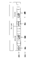
- FIG. 11 is a diagram showing an example (1) of HARQ feedback multiplexing according to the embodiment of the present invention.
- Information related to HARQ feedback multiplexing may be included in a signal associated with each data (eg, corresponding control signal), and the data receiving node may multiplex HARQ-ACK based on the information and transmit to the data transmitting node. .
- the information may be a feedback group indication.
- the information may be information used to determine the number of HARQ-ACK bits and bit positions (hereinafter referred to as information X).
- the information X may be, for example, a DAI (Downlink Assignment Index).
- This information may be toggle information for indicators related to HARQ feedback, and may be called NFI (New feedback indicator) or FGI (Feedback grouping indicator).
- NFI New feedback indicator
- FGI Field grouping indicator
- the data receiving node may multiplex and transmit HARQ-ACKs corresponding to data receptions associated with non-toggled NFIs to the data transmitting node.
- NFI New feedback indicator
- FGI Field grouping indicator
- Information X may be initialized when NFI is toggled.
- a transmission may be triggered.
- the predetermined condition may be, for example, that a predetermined time has passed since the last NFI reception, or that the timing is a predetermined time before the HARQ feedback resource corresponding to the last NFI reception. There may be.
- a signal for indicating toggling of NFI may be defined separately, and information indicating toggled/not toggled for multiple nodes may be collectively transmitted by the signal.
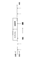
- FIG. 12 is a diagram showing an example (2) of HARQ feedback multiplexing according to the embodiment of the present invention.
- the data receiving node may decide which HARQ-ACKs to multiplex and feed back.
- HARQ-ACKs to be multiplexed and transmitted may be determined under constraints based on the order of reception of the corresponding data.
- the data-receiving node may include feedback information corresponding to successive data receptions from the earliest data reception among the data receptions for which feedback has not yet been performed. . That is, as shown in FIG. 12, the feedback information corresponding to the oldest data reception is transmitted in order, and the data receiving node may decide to what extent the feedback information corresponding to the data reception is to be included.
- HARQ-ACKs corresponding to all data reception in that slot may be multiplexed.
- the constraint that HARQ-ACKs corresponding to all data reception in the slot must be multiplexed may be applied only to data with the same priority.
- the priority may be the priority in either the PHY layer or the higher layer, the priority of HARQ-ACK, or the priority of corresponding data.
- the priority may be associated with the corresponding data reception traffic type, performance requirements (e.g. eMBB or URLLC).
- the data receiving node may transmit, to the data transmitting node, information indicating which of the received data the HARQ feedback corresponds to, together with the HARQ feedback information. For example, when performing K-bit HARQ feedback, the data receiving node transmits information (for example, slot index) related to the first data reception among the data receptions corresponding to K bits to the data transmitting node together with the HARQ feedback information. You may Also, when performing K-bit HARQ feedback, the data receiving node may transmit information indicating that it is K bits to the data transmitting node together with the HARQ feedback information.
- information for example, slot index
- the number of HARQ-ACK bits may be determined based on the amount of HARQ feedback resources. For example, the method for TBS (Transport Block Size) determination may also be applied to control information (eg UCI, DCI or HARQ-ACK) transmission. For example, the number of HARQ-ACK bits to be transmitted may be determined based on at least one of 1)-3) shown below.
- TBS Transport Block Size
- MCS index MCS index.
- RS Physical channels control signal
- PT-RS Phase tracking reference signal
- CSI-RS amount CSI-RS amount.
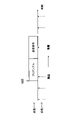
- FIG. 13 is a diagram showing an example (3) of HARQ feedback multiplexing according to the embodiment of the present invention.
- the unused bits may store predetermined information (eg, NACK).
- predetermined information eg, NACK
- the mapping between data reception and HARQ feedback bit sequences is determined based on the slots in which HARQ feedback is performed, and the positions of the unused bits in the HARQ feedback bit sequences are determined.
- bits other than bit #1, bit #2, bit #3 and bit #4 of the HARQ feedback shown in FIG. 13 may store the predetermined information.
- the multiplexed HARQ feedback resource is the HARQ feedback specified for each data corresponding to multiplexed HARQ-ACK. may be determined based on any of the resources for For example, based on the last received notification specifying the resource from the data transmitting node, the data receiving node may determine the HARQ feedback resource to multiplex.
- FIG. 14 is a diagram showing an example (1) of HARQ feedback transmission/reception according to the embodiment of the present invention.
- the HARQ feedback transmission procedure may be the same transmission procedure as the data transmission. That is, a data signal, a control signal, a reference signal and a preamble signal (when the above control rules A2 and B2 are applied) are transmission procedures for data transmission, and as shown in FIG. , HARQ feedback signals, control signals, reference signals and preamble signals may be transmitted. Also, if the above control rules B1 and B2 are applied, LBT may be performed before signaling.
- FIG. 15 is a diagram showing an example (2) of HARQ feedback transmission and reception according to the embodiment of the present invention.
- the HARQ feedback transmission procedure may be a different transmission procedure than the data transmission. That is, signals for HARQ feedback may be defined.
- a signal for HARQ feedback and a preamble signal (when the above control rules A2 and B2 are applied) are transmitted on designated resources without a control signal for reception. good too.
- the above control rules B1 and B2 it is not necessary to perform LBT before signal transmission.
- HARQ feedback resources signaled for corresponding data transmission may not be used by other nodes. Also, for example, if there is a data transmitting node or a data receiving node transmitting continuously or within a predetermined time gap before the HARQ feedback resource, LBT may not be performed.
- a data sending node may assume that HARQ feedback is sent from a data receiving node on a designated HARQ feedback resource. Also, the data transmission node may assume that the HARQ feedback will be transmitted by a predetermined timing.
- the predetermined timing may be timing based on Tmax described above.
- the data transmitting node may assume that HARQ feedback will be transmitted from the data receiving node on the specified HARQ feedback resource if certain conditions are met. Also, the data transmission node may assume that HARQ feedback will be transmitted by a predetermined timing if a predetermined condition is satisfied.
- the data transmission node may retransmit the corresponding data when a data reception or decoding failure is reported, or when HARQ feedback (for example, by a predetermined timing) cannot be received.
- Retransmission of data may be performed in the same manner as for the initial transmission. That is, the data signal, the control signal, the reference signal and the preamble signal (if the above control rules A2 and B2 are applied) may be transmitted from the data transmitting node, and the HARQ-ACK information may be sent from the data receiving node instead of the data. may be sent from Furthermore, in the case of the above control rules B1 and B2, LBT may be performed before signal transmission.
- retransmission of data may be performed using a different method from the initial transmission. That is, methods for data retransmission may be defined. For example, as information related to HARQ feedback, a resource for data retransmission may be notified from the data receiving node to the data transmitting node. When retransmitting data on the notification resource, the data signal, the reference signal, and the preamble signal (when the above control rules A2 and B2 are applied) are transmitted from the data transmission node without control information for reception. good too. Also, for example, when data is retransmitted using a resource other than the notification resource, the data may be retransmitted in the same manner as in the initial transmission. Furthermore, in the case of the above control rules B1 and B2, LBT may be performed before signal transmission.
- the data transmission node may request the data reception node to retransmit the HARQ feedback.
- the base station 10 or terminal 20 autonomously selects resources for DL, UL or SL transmission, it is possible to clarify acknowledgment of data reception, retransmission request and retransmission operation.
- the base stations 10 and terminals 20 contain the functionality to implement the embodiments described above. However, each of the base station 10 and the terminal 20 may have only the functions proposed in any of the embodiments.
- FIG. 16 is a diagram showing an example of the functional configuration of the base station 10.
- the base station 10 has a transmitting section 110, a receiving section 120, a setting section 130, and a control section 140.
- the functional configuration shown in FIG. 16 is merely an example. As long as the operation according to the embodiment of the present invention can be executed, the functional division and the names of the functional units may be arbitrary.
- the transmitting unit 110 and the receiving unit 120 may be called a communication unit.
- the transmission unit 110 includes a function of generating a signal to be transmitted to the terminal 20 side and wirelessly transmitting the signal.
- the receiving unit 120 includes a function of receiving various signals transmitted from the terminal 20 and acquiring, for example, higher layer information from the received signals.
- the transmitting unit 110 has a function of transmitting NR-PSS, NR-SSS, NR-PBCH, DL/UL control signals, DL data, etc. to the terminal 20 . Also, the transmission unit 110 transmits the setting information and the like described in the embodiment.
- the setting unit 130 stores preset setting information and various setting information to be transmitted to the terminal 20 in the storage device, and reads them from the storage device as necessary.
- the control unit 140 performs overall control of the base station 10 including, for example, control related to signal transmission/reception and control related to LBT. It should be noted that the functional unit related to signal transmission in control unit 140 may be included in transmitting unit 110 , and the functional unit related to signal reception in control unit 140 may be included in receiving unit 120 . Also, the transmitting unit 110 and the receiving unit 120 may be called a transmitter and a receiver, respectively.
- FIG. 17 is a diagram showing an example of the functional configuration of the terminal 20.
- the terminal 20 has a transmitting section 210, a receiving section 220, a setting section 230, and a control section 240.
- the functional configuration shown in FIG. 17 is merely an example. As long as the operation according to the embodiment of the present invention can be executed, the functional division and the names of the functional units may be arbitrary.
- the transmitting unit 210 and the receiving unit 220 may be called a communication unit.
- the transmission unit 210 creates a transmission signal from the transmission data and wirelessly transmits the transmission signal.
- the receiving unit 220 wirelessly receives various signals and acquires a higher layer signal from the received physical layer signal. Also, the transmitting unit 210 transmits HARQ-ACK, and the receiving unit 220 receives the setting information and the like described in the embodiment.
- the setting unit 230 stores various types of setting information received from the base station 10 by the receiving unit 220 in the storage device, and reads them from the storage device as necessary.
- the setting unit 230 also stores preset setting information.
- the control unit 240 performs overall control of the terminal 20 including control related to signal transmission/reception and control related to LBT. It should be noted that the functional unit related to signal transmission in control unit 240 may be included in transmitting unit 210 , and the functional unit related to signal reception in control unit 240 may be included in receiving unit 220 . Also, the transmitting section 210 and the receiving section 220 may be called a transmitter and a receiver, respectively.
- each functional block may be implemented using one device that is physically or logically coupled, or directly or indirectly using two or more devices that are physically or logically separated (e.g. , wired, wireless, etc.) and may be implemented using these multiple devices.
- a functional block may be implemented by combining software in the one device or the plurality of devices.
- Functions include judging, determining, determining, calculating, calculating, processing, deriving, investigating, searching, checking, receiving, transmitting, outputting, accessing, resolving, selecting, choosing, establishing, comparing, assuming, expecting, assuming, Broadcasting, notifying, communicating, forwarding, configuring, reconfiguring, allocating, mapping, assigning, etc. can't
- a functional block (component) that performs transmission is called a transmitting unit or transmitter.
- the implementation method is not particularly limited.
- the base station 10, the terminal 20, etc. may function as a computer that performs processing of the wireless communication method of the present disclosure.
- FIG. 18 is a diagram illustrating an example of hardware configurations of the base station 10 and the terminal 20 according to an embodiment of the present disclosure.
- the base station 10 and terminal 20 described above are physically configured as a computer device including a processor 1001, a storage device 1002, an auxiliary storage device 1003, a communication device 1004, an input device 1005, an output device 1006, a bus 1007, and the like. good too.
- the term "apparatus” can be read as a circuit, device, unit, or the like.
- the hardware configuration of the base station 10 and terminal 20 may be configured to include one or more of each device shown in the figure, or may be configured without some devices.
- Each function of the base station 10 and the terminal 20 is performed by the processor 1001 performing calculations and controlling communication by the communication device 1004 by loading predetermined software (programs) onto hardware such as the processor 1001 and the storage device 1002. or by controlling at least one of data reading and writing in the storage device 1002 and the auxiliary storage device 1003 .
- the processor 1001 for example, operates an operating system and controls the entire computer.
- the processor 1001 may be configured with a central processing unit (CPU) including an interface with peripheral devices, a control device, an arithmetic device, registers, and the like.
- CPU central processing unit
- the control unit 140 , the control unit 240 and the like described above may be implemented by the processor 1001 .
- the processor 1001 reads programs (program codes), software modules, data, etc. from at least one of the auxiliary storage device 1003 and the communication device 1004 to the storage device 1002, and executes various processes according to them.
- programs program codes
- software modules software modules
- data etc.
- the program a program that causes a computer to execute at least part of the operations described in the above embodiments is used.
- control unit 140 of base station 10 shown in FIG. 16 may be implemented by a control program stored in storage device 1002 and operated by processor 1001 .
- FIG. Processor 1001 may be implemented by one or more chips.
- the program may be transmitted from a network via an electric communication line.
- the storage device 1002 is a computer-readable recording medium, for example, ROM (Read Only Memory), EPROM (Erasable Programmable ROM), EEPROM (Electrically Erasable Programmable ROM), RAM (Random Access Memory), etc. may be configured.
- the storage device 1002 may also be called a register, cache, main memory (main storage device), or the like.
- the storage device 1002 can store executable programs (program code), software modules, etc. for implementing a communication method according to an embodiment of the present disclosure.
- the auxiliary storage device 1003 is a computer-readable recording medium, for example, an optical disk such as a CD-ROM (Compact Disc ROM), a hard disk drive, a flexible disk, a magneto-optical disk (for example, a compact disk, a digital versatile disk, a Blu -ray disk), smart card, flash memory (eg, card, stick, key drive), floppy disk, magnetic strip, and/or the like.
- the storage medium described above may be, for example, a database, server, or other suitable medium including at least one of storage device 1002 and secondary storage device 1003 .
- the communication device 1004 is hardware (transmitting/receiving device) for communicating between computers via at least one of a wired network and a wireless network, and is also called a network device, a network controller, a network card, a communication module, or the like.
- the communication device 1004 includes a high-frequency switch, a duplexer, a filter, a frequency synthesizer, etc., in order to realize at least one of, for example, frequency division duplex (FDD) and time division duplex (TDD).
- FDD frequency division duplex
- TDD time division duplex
- the transceiver may be physically or logically separate implementations for the transmitter and receiver.
- the input device 1005 is an input device (for example, keyboard, mouse, microphone, switch, button, sensor, etc.) that receives input from the outside.
- the output device 1006 is an output device (for example, display, speaker, LED lamp, etc.) that outputs to the outside. Note that the input device 1005 and the output device 1006 may be integrated (for example, a touch panel).
- Each device such as the processor 1001 and the storage device 1002 is connected by a bus 1007 for communicating information.
- the bus 1007 may be configured using a single bus, or may be configured using different buses between devices.
- the base station 10 and the terminal 20 include hardware such as microprocessors, digital signal processors (DSPs), ASICs (Application Specific Integrated Circuits), PLDs (Programmable Logic Devices), and FPGAs (Field Programmable Gate Arrays). , and part or all of each functional block may be implemented by the hardware.
- processor 1001 may be implemented using at least one of these pieces of hardware.
- a control unit that autonomously determines a first resource to be used for transmission, and another communication device that transmits data using the first resource. and a receiver for receiving feedback information corresponding to the data on a second resource determined autonomously or heteronomously by the other communication device.
- the receiving unit may assume that the second resource is allocated in a certain interval starting from the time at which the first resource is allocated.
- the control unit determines a third resource to be used for receiving feedback information corresponding to the data based on beam timing of the other communication device, and the transmission unit indicates the third resource. Information may be sent to the other communication device, and the receiving unit may receive the feedback information on the third resource.
- the control unit determines a resource group that is a candidate for a third resource to be used for receiving feedback information corresponding to the data, and the transmission unit transmits information indicating the resource group to the other communication device. and the other communication device may autonomously determine the third resource from among the resource group, and the receiver may receive the feedback information in the third resource.
- the transmitting unit transmits the data to the other communication device using resources for retransmission of the data included in the feedback information. You can resend.
- the base station 10 or terminal 20 autonomously selects resources for DL, UL, or SL transmission, feedback corresponding to data reception can be received within the designated resource group.
- control procedure for autonomously determining a first resource to be used for transmission and a transmission procedure for transmitting data to another communication device using the first resource.
- a receiving procedure for receiving feedback information corresponding to the data on a second resource determined autonomously or heteronomously by the other communication device are provided.
- the operations of a plurality of functional units may be physically performed by one component, or the operations of one functional unit may be physically performed by a plurality of components.
- the processing order may be changed as long as there is no contradiction.
- the base station 10 and the terminal 20 have been described using functional block diagrams for convenience of explanation of processing, such devices may be implemented in hardware, software, or a combination thereof.
- the software operated by the processor of the base station 10 according to the embodiment of the present invention and the software operated by the processor of the terminal 20 according to the embodiment of the present invention are stored in random access memory (RAM), flash memory, read-only memory, respectively. (ROM), EPROM, EEPROM, register, hard disk (HDD), removable disk, CD-ROM, database, server, or any other appropriate storage medium.
- notification of information is not limited to the aspects/embodiments described in the present disclosure, and may be performed using other methods.
- notification of information includes physical layer signaling (e.g., DCI (Downlink Control Information), UCI (Uplink Control Information)), higher layer signaling (e.g., RRC (Radio Resource Control) signaling, MAC (Medium Access Control) signaling, It may be implemented by broadcast information (MIB (Master Information Block), SIB (System Information Block)), other signals, or a combination thereof.
- RRC signaling may also be called an RRC message, for example, RRC It may be a connection setup (RRC Connection Setup) message, an RRC connection reconfiguration message, or the like.
- Each aspect/embodiment described in the present disclosure includes LTE (Long Term Evolution), LTE-A (LTE-Advanced), SUPER 3G, IMT-Advanced, 4G (4th generation mobile communication system), 5G (5th generation mobile communication system) system), FRA (Future Radio Access), NR (new Radio), W-CDMA (registered trademark), GSM (registered trademark), CDMA2000, UMB (Ultra Mobile Broadband), IEEE 802.11 (Wi-Fi (registered trademark) )), IEEE 802.16 (WiMAX (registered trademark)), IEEE 802.20, UWB (Ultra-WideBand), Bluetooth (registered trademark), and other suitable systems and extended It may be applied to at least one of the next generation systems. Also, a plurality of systems may be applied in combination (for example, a combination of at least one of LTE and LTE-A and 5G, etc.).
- a specific operation performed by the base station 10 in this specification may be performed by its upper node in some cases.
- various operations performed for communication with terminal 20 may be performed by base station 10 and other network nodes other than base station 10 (eg, but not limited to MME or S-GW).
- base station 10 e.g, but not limited to MME or S-GW
- the other network node may be a combination of a plurality of other network nodes (for example, MME and S-GW).
- Information, signals, etc. described in the present disclosure may be output from a higher layer (or a lower layer) to a lower layer (or a higher layer). It may be input and output via multiple network nodes.
- Input/output information may be stored in a specific location (for example, memory) or managed using a management table. Input/output information and the like can be overwritten, updated, or appended. The output information and the like may be deleted. The entered information and the like may be transmitted to another device.
- the determination in the present disclosure may be performed by a value represented by 1 bit (0 or 1), may be performed by a boolean value (Boolean: true or false), or may be performed by comparing numerical values (e.g. , comparison with a predetermined value).
- Software whether referred to as software, firmware, middleware, microcode, hardware description language or otherwise, includes instructions, instruction sets, code, code segments, program code, programs, subprograms, and software modules. , applications, software applications, software packages, routines, subroutines, objects, executables, threads of execution, procedures, functions, and the like.
- software, instructions, information, etc. may be transmitted and received via a transmission medium.
- the software uses at least one of wired technology (coaxial cable, fiber optic cable, twisted pair, digital subscriber line (DSL), etc.) and wireless technology (infrared, microwave, etc.) to website, Wired and/or wireless technologies are included within the definition of transmission medium when sent from a server or other remote source.
- wired technology coaxial cable, fiber optic cable, twisted pair, digital subscriber line (DSL), etc.
- wireless technology infrared, microwave, etc.
- data, instructions, commands, information, signals, bits, symbols, chips, etc. may refer to voltages, currents, electromagnetic waves, magnetic fields or magnetic particles, light fields or photons, or any of these. may be represented by a combination of
- the channel and/or symbols may be signaling.
- a signal may also be a message.
- a component carrier may also be called a carrier frequency, a cell, a frequency carrier, or the like.
- system and “network” used in this disclosure are used interchangeably.
- information, parameters, etc. described in the present disclosure may be expressed using absolute values, may be expressed using relative values from a predetermined value, or may be expressed using other corresponding information.
- radio resources may be indexed.
- base station BS
- radio base station base station
- base station fixed station
- NodeB nodeB
- eNodeB eNodeB
- gNodeB gNodeB
- a base station can accommodate one or more (eg, three) cells.
- the overall coverage area of the base station can be partitioned into multiple smaller areas, each smaller area being associated with a base station subsystem (e.g., an indoor small base station (RRH:
- RRH indoor small base station
- the term "cell” or “sector” refers to part or all of the coverage area of at least one of the base stations and base station subsystems serving communication services in this coverage.
- MS Mobile Station
- UE User Equipment
- a mobile station is defined by those skilled in the art as a subscriber station, mobile unit, subscriber unit, wireless unit, remote unit, mobile device, wireless device, wireless communication device, remote device, mobile subscriber station, access terminal, mobile terminal, wireless It may also be called a terminal, remote terminal, handset, user agent, mobile client, client, or some other suitable term.
- At least one of the base station and mobile station may be called a transmitting device, a receiving device, a communication device, or the like.
- At least one of the base station and the mobile station may be a device mounted on a mobile object, the mobile object itself, or the like.
- the mobile object may be a vehicle (e.g., car, airplane, etc.), an unmanned mobile object (e.g., drone, self-driving car, etc.), or a robot (manned or unmanned ).
- at least one of the base station and the mobile station includes devices that do not necessarily move during communication operations.
- at least one of the base station and mobile station may be an IoT (Internet of Things) device such as a sensor.
- IoT Internet of Things
- the base station in the present disclosure may be read as a user terminal.
- communication between a base station and a user terminal is replaced with communication between a plurality of terminals 20 (for example, D2D (Device-to-Device), V2X (Vehicle-to-Everything), etc.)
- the terminal 20 may have the functions of the base station 10 described above.
- words such as "up” and “down” may be replaced with words corresponding to inter-terminal communication (for example, "side”).
- uplink channels, downlink channels, etc. may be read as side channels.
- user terminals in the present disclosure may be read as base stations.
- the base station may have the functions that the above-described user terminal has.
- determining and “determining” used in this disclosure may encompass a wide variety of actions.
- “Judgement” and “determination” are, for example, judging, calculating, computing, processing, deriving, investigating, looking up, searching, inquiring (eg, lookup in a table, database, or other data structure), ascertaining as “judged” or “determined”, and the like.
- "judgment” and “determination” are used for receiving (e.g., receiving information), transmitting (e.g., transmitting information), input, output, access (accessing) (for example, accessing data in memory) may include deeming that a "judgment” or “decision” has been made.
- judgment and “decision” are considered to be “judgment” and “decision” by resolving, selecting, choosing, establishing, comparing, etc. can contain.
- judgment and “decision” may include considering that some action is “judgment” and “decision”.
- judgment (decision) may be read as “assuming”, “expecting”, “considering”, or the like.
- connection means any direct or indirect connection or coupling between two or more elements, It can include the presence of one or more intermediate elements between two elements being “connected” or “coupled.” Couplings or connections between elements may be physical, logical, or a combination thereof. For example, “connection” may be read as "access”.
- two elements are defined using at least one of one or more wires, cables, and printed electrical connections and, as some non-limiting and non-exhaustive examples, in the radio frequency domain. , electromagnetic energy having wavelengths in the microwave and optical (both visible and invisible) regions, and the like.
- the reference signal can also be abbreviated as RS (Reference Signal), and may also be called Pilot depending on the applicable standard.
- RS Reference Signal
- any reference to elements using the "first,” “second,” etc. designations used in this disclosure does not generally limit the quantity or order of those elements. These designations may be used in this disclosure as a convenient method of distinguishing between two or more elements. Thus, reference to a first and second element does not imply that only two elements can be employed or that the first element must precede the second element in any way.
- a radio frame may consist of one or more frames in the time domain. Each frame or frames in the time domain may be referred to as a subframe. A subframe may also consist of one or more slots in the time domain. A subframe may be of a fixed length of time (eg, 1 ms) independent of numerology.
- a numerology may be a communication parameter that applies to the transmission and/or reception of a signal or channel. Numerology, for example, subcarrier spacing (SCS), bandwidth, symbol length, cyclic prefix length, transmission time interval (TTI), number of symbols per TTI, radio frame configuration, transceiver It may indicate at least one of certain filtering operations performed in the frequency domain, certain windowing operations performed by the transceiver in the time domain, and/or the like.
- SCS subcarrier spacing
- TTI transmission time interval
- transceiver It may indicate at least one of certain filtering operations performed in the frequency domain, certain windowing operations performed by the transceiver in the time domain, and/or the like.
- a slot may consist of one or more symbols (OFDM (Orthogonal Frequency Division Multiplexing) symbol, SC-FDMA (Single Carrier Frequency Division Multiple Access) symbol, etc.) in the time domain.
- a slot may be a unit of time based on numerology.
- a slot may contain multiple mini-slots. Each minislot may consist of one or more symbols in the time domain. A minislot may also be referred to as a subslot. A minislot may consist of fewer symbols than a slot.
- PDSCH (or PUSCH) transmitted in time units larger than minislots may be referred to as PDSCH (or PUSCH) mapping type A.
- PDSCH (or PUSCH) transmitted using minislots may be referred to as PDSCH (or PUSCH) mapping type B.
- Radio frames, subframes, slots, minislots and symbols all represent time units when transmitting signals. Radio frames, subframes, slots, minislots and symbols may be referred to by other corresponding designations.
- one subframe may be called a Transmission Time Interval (TTI)
- TTI Transmission Time Interval
- TTI Transmission Time Interval
- TTI Transmission Time Interval
- one slot or one minislot may be called a TTI.
- TTI Transmission Time Interval
- at least one of the subframe and TTI may be a subframe (1 ms) in existing LTE, a period shorter than 1 ms (eg, 1-13 symbols), or a period longer than 1 ms may be Note that the unit representing the TTI may be called a slot, mini-slot, or the like instead of a subframe.
- TTI refers to, for example, the minimum scheduling time unit in wireless communication.
- the base station performs scheduling to allocate radio resources (frequency bandwidth, transmission power, etc. that can be used by each terminal 20) to each terminal 20 on a TTI basis.
- radio resources frequency bandwidth, transmission power, etc. that can be used by each terminal 20
- TTI is not limited to this.
- a TTI may be a transmission time unit such as a channel-encoded data packet (transport block), code block, or codeword, or may be a processing unit such as scheduling and link adaptation. Note that when a TTI is given, the time interval (for example, the number of symbols) in which transport blocks, code blocks, codewords, etc. are actually mapped may be shorter than the TTI.
- one or more TTIs may be the minimum scheduling time unit. Also, the number of slots (the number of mini-slots) constituting the minimum time unit of the scheduling may be controlled.
- a TTI having a time length of 1 ms may be called a normal TTI (TTI in LTE Rel. 8-12), normal TTI, long TTI, normal subframe, normal subframe, long subframe, slot, or the like.
- a TTI that is shorter than a normal TTI may be called a shortened TTI, a short TTI, a partial or fractional TTI, a shortened subframe, a short subframe, a minislot, a subslot, a slot, and the like.
- the long TTI (e.g., normal TTI, subframe, etc.) may be replaced with a TTI having a time length exceeding 1 ms
- the short TTI e.g., shortened TTI, etc.
- a TTI having the above TTI length may be read instead.
- a resource block is a resource allocation unit in the time domain and the frequency domain, and may include one or more consecutive subcarriers in the frequency domain.
- the number of subcarriers included in the RB may be the same regardless of the numerology, and may be 12, for example.
- the number of subcarriers included in an RB may be determined based on numerology.
- the time domain of an RB may include one or more symbols and may be 1 slot, 1 minislot, 1 subframe, or 1 TTI long.
- One TTI, one subframe, etc. may each consist of one or more resource blocks.
- One or more RBs are physical resource blocks (PRBs), sub-carrier groups (SCGs), resource element groups (REGs), PRB pairs, RB pairs, etc. may be called.
- PRBs physical resource blocks
- SCGs sub-carrier groups
- REGs resource element groups
- PRB pairs RB pairs, etc. may be called.
- a resource block may be composed of one or more resource elements (RE: Resource Element).
- RE Resource Element
- 1 RE may be a radio resource region of 1 subcarrier and 1 symbol.
- a bandwidth part (which may also be called a bandwidth part) may represent a subset of contiguous common resource blocks (RBs) for a certain numerology on a certain carrier.
- the common RB may be identified by an RB index based on the common reference point of the carrier.
- PRBs may be defined in a BWP and numbered within that BWP.
- the BWP may include a BWP for UL (UL BWP) and a BWP for DL (DL BWP).
- UL BWP UL BWP
- DL BWP DL BWP
- One or more BWPs may be configured for terminal 20 within one carrier.
- At least one of the configured BWPs may be active, and the terminal 20 may not expect to transmit or receive a given signal/channel outside the active BWP.
- “cell”, “carrier”, etc. in the present disclosure may be read as "BWP”.
- radio frames, subframes, slots, minislots and symbols described above are only examples.
- the number of subframes contained in a radio frame the number of slots per subframe or radio frame, the number of minislots contained within a slot, the number of symbols and RBs contained in a slot or minislot, the number of Configurations such as the number of subcarriers, the number of symbols in a TTI, the symbol length, the cyclic prefix (CP) length, etc.
- CP cyclic prefix
- a and B are different may mean “A and B are different from each other.”
- the term may also mean that "A and B are different from C”.
- Terms such as “separate,” “coupled,” etc. may also be interpreted in the same manner as “different.”
- notification of predetermined information is not limited to being performed explicitly, but may be performed implicitly (for example, not notifying the predetermined information). good too.
- the base station 10 and the terminal 20, or the transmission node and the reception node are examples of communication devices.
- base station 110 transmitting unit 120 receiving unit 130 setting unit 140 control unit 20 terminal 210 transmitting unit 220 receiving unit 230 setting unit 240 control unit 30 core network 1001 processor 1002 storage device 1003 auxiliary storage device 1004 communication device 1005 input device 1006 output device
Abstract
Description
2)通信装置からデータを受信し、受信データに係る所定の信号を送信する
2)RSの量。例えば、DMRS(Demodulation reference signal)、PT-RS(Phase tracking reference signal)、CSI-RSの量。
3)上位レイヤパラメータ
次に、これまでに説明した処理及び動作を実行する基地局10及び端末20の機能構成例を説明する。基地局10及び端末20は上述した実施例を実行する機能を含む。ただし、基地局10及び端末20はそれぞれ、実施例のうちのいずれかの提案の機能のみを備えることとしてもよい。
図16は、基地局10の機能構成の一例を示す図である。図16に示されるように、基地局10は、送信部110と、受信部120と、設定部130と、制御部140とを有する。図16に示される機能構成は一例に過ぎない。本発明の実施の形態に係る動作を実行できるのであれば、機能区分及び機能部の名称はどのようなものでもよい。送信部110と受信部120とを通信部と呼んでもよい。
図17は、端末20の機能構成の一例を示す図である。図17に示されるように、端末20は、送信部210と、受信部220と、設定部230と、制御部240とを有する。図17に示される機能構成は一例に過ぎない。本発明の実施の形態に係る動作を実行できるのであれば、機能区分及び機能部の名称はどのようなものでもよい。送信部210と受信部220とを通信部と呼んでもよい。
上記実施形態の説明に用いたブロック図(図16及び図17)は、機能単位のブロックを示している。これらの機能ブロック(構成部)は、ハードウェア及びソフトウェアの少なくとも一方の任意の組み合わせによって実現される。また、各機能ブロックの実現方法は特に限定されない。すなわち、各機能ブロックは、物理的又は論理的に結合した1つの装置を用いて実現されてもよいし、物理的又は論理的に分離した2つ以上の装置を直接的又は間接的に(例えば、有線、無線などを用いて)接続し、これら複数の装置を用いて実現されてもよい。機能ブロックは、上記1つの装置又は上記複数の装置にソフトウェアを組み合わせて実現されてもよい。
以上、説明したように、本発明の実施の形態によれば、送信に使用する第1のリソースを自律的に決定する制御部と、前記第1のリソースを使用してデータを他の通信装置に送信する送信部と、前記データに対応するフィードバック情報を、前記他の通信装置が自律的又は他律的に決定した第2のリソースにおいて受信する受信部とを有する通信装置が提供される。
以上、本発明の実施の形態を説明してきたが、開示される発明はそのような実施形態に限定されず、当業者は様々な変形例、修正例、代替例、置換例等を理解するであろう。発明の理解を促すため具体的な数値例を用いて説明がなされたが、特に断りのない限り、それらの数値は単なる一例に過ぎず適切な如何なる値が使用されてもよい。上記の説明における項目の区分けは本発明に本質的ではなく、2以上の項目に記載された事項が必要に応じて組み合わせて使用されてよいし、ある項目に記載された事項が、別の項目に記載された事項に(矛盾しない限り)適用されてよい。機能ブロック図における機能部又は処理部の境界は必ずしも物理的な部品の境界に対応するとは限らない。複数の機能部の動作が物理的には1つの部品で行われてもよいし、あるいは1つの機能部の動作が物理的には複数の部品により行われてもよい。実施の形態で述べた処理手順については、矛盾の無い限り処理の順序を入れ替えてもよい。処理説明の便宜上、基地局10及び端末20は機能的なブロック図を用いて説明されたが、そのような装置はハードウェアで、ソフトウェアで又はそれらの組み合わせで実現されてもよい。本発明の実施の形態に従って基地局10が有するプロセッサにより動作するソフトウェア及び本発明の実施の形態に従って端末20が有するプロセッサにより動作するソフトウェアはそれぞれ、ランダムアクセスメモリ(RAM)、フラッシュメモリ、読み取り専用メモリ(ROM)、EPROM、EEPROM、レジスタ、ハードディスク(HDD)、リムーバブルディスク、CD-ROM、データベース、サーバその他の適切な如何なる記憶媒体に保存されてもよい。
110 送信部
120 受信部
130 設定部
140 制御部
20 端末
210 送信部
220 受信部
230 設定部
240 制御部
30 コアネットワーク
1001 プロセッサ
1002 記憶装置
1003 補助記憶装置
1004 通信装置
1005 入力装置
1006 出力装置
Claims (6)
- 送信に使用する第1のリソースを自律的に決定する制御部と、
前記第1のリソースを使用してデータを他の通信装置に送信する送信部と、
前記データに対応するフィードバック情報を、前記他の通信装置が自律的又は他律的に決定した第2のリソースにおいて受信する受信部とを有する通信装置。 - 前記受信部は、前記第2のリソースが前記第1のリソースが配置される時刻から始まるある区間に配置されると想定する請求項1記載の通信装置。
- 前記制御部は、前記データに対応するフィードバック情報の受信に使用する第3のリソースを、前記他の通信装置のビームのタイミングに基づいて決定し、
前記送信部は、前記第3のリソースを示す情報を前記他の通信装置に送信し、
前記受信部は、前記第3のリソースにおいて前記フィードバック情報を受信する請求項1記載の通信装置。 - 前記制御部は、前記データに対応するフィードバック情報の受信に使用する第3のリソースの候補となるリソース群を決定し、
前記送信部は、前記リソース群を示す情報を前記他の通信装置に送信し、
前記他の通信装置は、前記第3のリソースを前記リソース群の中から自律的に決定し、
前記受信部は、前記第3のリソースにおいて前記フィードバック情報を受信する請求項1記載の通信装置。 - 前記受信部が前記データの受信失敗を示す前記フィードバック情報を受信した場合、前記送信部は、前記フィードバック情報に含まれる前記データの再送用のリソースを使用して前記データを前記他の通信装置に再送する請求項1記載の通信装置。
- 送信に使用する第1のリソースを自律的に決定する制御手順と、
前記第1のリソースを使用してデータを他の通信装置に送信する送信手順と、
前記データに対応するフィードバック情報を、前記他の通信装置が自律的又は他律的に決定した第2のリソースにおいて受信する受信手順とを通信装置が実行する通信方法。
Priority Applications (4)
| Application Number | Priority Date | Filing Date | Title |
|---|---|---|---|
| JP2023503577A JPWO2022185421A1 (ja) | 2021-03-02 | 2021-03-02 | |
| EP21928997.2A EP4304232A1 (en) | 2021-03-02 | 2021-03-02 | Communication device and communication method |
| PCT/JP2021/008022 WO2022185421A1 (ja) | 2021-03-02 | 2021-03-02 | 通信装置及び通信方法 |
| CN202180094558.9A CN116918372A (zh) | 2021-03-02 | 2021-03-02 | 通信装置和通信方法 |
Applications Claiming Priority (1)
| Application Number | Priority Date | Filing Date | Title |
|---|---|---|---|
| PCT/JP2021/008022 WO2022185421A1 (ja) | 2021-03-02 | 2021-03-02 | 通信装置及び通信方法 |
Publications (1)
| Publication Number | Publication Date |
|---|---|
| WO2022185421A1 true WO2022185421A1 (ja) | 2022-09-09 |
Family
ID=83154006
Family Applications (1)
| Application Number | Title | Priority Date | Filing Date |
|---|---|---|---|
| PCT/JP2021/008022 WO2022185421A1 (ja) | 2021-03-02 | 2021-03-02 | 通信装置及び通信方法 |
Country Status (4)
| Country | Link |
|---|---|
| EP (1) | EP4304232A1 (ja) |
| JP (1) | JPWO2022185421A1 (ja) |
| CN (1) | CN116918372A (ja) |
| WO (1) | WO2022185421A1 (ja) |
Citations (3)
| Publication number | Priority date | Publication date | Assignee | Title |
|---|---|---|---|---|
| WO2019139876A1 (en) * | 2018-01-10 | 2019-07-18 | Idac Holdings, Inc. | Data transmissions and harq-ack associated with an unlicensed spectrum |
| JP2019531640A (ja) * | 2016-08-25 | 2019-10-31 | クアルコム,インコーポレイテッド | デバイス間通信における複数の送信のための自律的リソース選択 |
| JP2020511824A (ja) * | 2017-03-13 | 2020-04-16 | 華為技術有限公司Huawei Technologies Co.,Ltd. | 情報送信方法及び装置 |
-
2021
- 2021-03-02 EP EP21928997.2A patent/EP4304232A1/en active Pending
- 2021-03-02 JP JP2023503577A patent/JPWO2022185421A1/ja active Pending
- 2021-03-02 WO PCT/JP2021/008022 patent/WO2022185421A1/ja active Application Filing
- 2021-03-02 CN CN202180094558.9A patent/CN116918372A/zh active Pending
Patent Citations (3)
| Publication number | Priority date | Publication date | Assignee | Title |
|---|---|---|---|---|
| JP2019531640A (ja) * | 2016-08-25 | 2019-10-31 | クアルコム,インコーポレイテッド | デバイス間通信における複数の送信のための自律的リソース選択 |
| JP2020511824A (ja) * | 2017-03-13 | 2020-04-16 | 華為技術有限公司Huawei Technologies Co.,Ltd. | 情報送信方法及び装置 |
| WO2019139876A1 (en) * | 2018-01-10 | 2019-07-18 | Idac Holdings, Inc. | Data transmissions and harq-ack associated with an unlicensed spectrum |
Non-Patent Citations (1)
| Title |
|---|
| "5G Evolution and 6G", NTT DOCOMO, INC WHITE PAPER, January 2020 (2020-01-01) |
Also Published As
| Publication number | Publication date |
|---|---|
| EP4304232A1 (en) | 2024-01-10 |
| CN116918372A (zh) | 2023-10-20 |
| JPWO2022185421A1 (ja) | 2022-09-09 |
Similar Documents
| Publication | Publication Date | Title |
|---|---|---|
| WO2022079876A1 (ja) | 端末 | |
| WO2021171594A1 (ja) | 端末 | |
| WO2022201398A1 (ja) | 通信装置、及び送信方法 | |
| WO2022185421A1 (ja) | 通信装置及び通信方法 | |
| WO2022185420A1 (ja) | 通信装置及び通信方法 | |
| US20240137156A1 (en) | Communication device and communication method | |
| US20240137157A1 (en) | Communication device and communication method | |
| WO2022201263A1 (ja) | 通信装置及び通信方法 | |
| WO2022219737A1 (ja) | 送信ノード及び送信方法 | |
| WO2022185500A1 (ja) | 通信装置及び通信方法 | |
| WO2022176214A1 (ja) | 送信ノード及び通信方法 | |
| WO2022201402A1 (ja) | 端末、基地局及び通信方法 | |
| WO2022201548A1 (ja) | 送信ノード及び送信方法 | |
| WO2022185548A1 (ja) | 通信装置及び通信方法 | |
| WO2022185549A1 (ja) | 通信装置及び通信方法 | |
| WO2022190392A1 (ja) | 通信装置及び通信方法 | |
| WO2022190391A1 (ja) | 通信装置及び通信方法 | |
| WO2022190393A1 (ja) | 通信装置及び通信方法 | |
| WO2022190394A1 (ja) | 通信装置及び通信方法 | |
| WO2022190396A1 (ja) | 通信装置及び通信方法 | |
| WO2023053231A1 (ja) | 端末及び無線通信方法 | |
| WO2022190397A1 (ja) | 通信装置及び通信方法 | |
| WO2022190395A1 (ja) | 通信装置及び通信方法 | |
| WO2022201397A1 (ja) | 通信装置、及び受信方法 | |
| WO2023053233A1 (ja) | 端末及び無線通信方法 |
Legal Events
| Date | Code | Title | Description |
|---|---|---|---|
| 121 | Ep: the epo has been informed by wipo that ep was designated in this application |
Ref document number: 21928997 Country of ref document: EP Kind code of ref document: A1 |
|
| WWE | Wipo information: entry into national phase |
Ref document number: 2023503577 Country of ref document: JP |
|
| WWE | Wipo information: entry into national phase |
Ref document number: 18277162 Country of ref document: US |
|
| WWE | Wipo information: entry into national phase |
Ref document number: 202180094558.9 Country of ref document: CN |
|
| WWE | Wipo information: entry into national phase |
Ref document number: 2021928997 Country of ref document: EP |
|
| NENP | Non-entry into the national phase |
Ref country code: DE |
|
| ENP | Entry into the national phase |
Ref document number: 2021928997 Country of ref document: EP Effective date: 20231002 |