以下、本発明の実施形態について説明する。
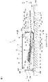
図1は、実施形態に係るケース1の内部を一側方から見た図、図2はケース1の底面図、図3は図1のIII-III断面図である。
Embodiments of the present invention will be described below.
1 is a side view of the inside of a case 1 according to the embodiment, FIG. 2 is a bottom view of the case 1, and FIG. 3 is a cross-sectional view taken along line III-III of FIG.
図1に示すように、ケース1は、その内部に、部品としての複数の電子部品(図1に図示)Mをバラの状態で収容する。複数の電子部品Mを収容したケース1は、フィーダ100に着脱可能にセットされる。本実施形態のフィーダ100は、振動することにより、ケース1内において電子部品Mを搬送してケース1から排出し、その電子部品Mを不図示の実装装置に供給する装置である。本実施形態の電子部品Mは、例えば長手方向の長さが1.2mm以下の微小な直方体状の電子部品である。そのような電子部品としては、コンデンサやインダクタ等が挙げられるが、本実施形態はこれらに限定されない。
As shown in FIG. 1, the case 1 accommodates therein a plurality of electronic components (shown in FIG. 1) M as components in a loose state. A case 1 containing a plurality of electronic components M is detachably set on a feeder 100 . The feeder 100 of this embodiment is a device that conveys the electronic component M in the case 1 by vibrating, discharges the electronic component M from the case 1, and supplies the electronic component M to a mounting device (not shown). The electronic component M of the present embodiment is, for example, a minute rectangular parallelepiped electronic component with a longitudinal length of 1.2 mm or less. Such electronic components include capacitors, inductors, and the like, but the present embodiment is not limited to these.
なお、図1、図2及び図3のいずれかに記載の矢印X、矢印Y、矢印Zは、フィーダ100にセットされた状態でのケース1の左右方向、前後方向、上下方向をそれぞれ示している。そして、左右方向Xにおいて左方をX1、右方をX2、前後方向Yにおいて前方をY1、後方をY2、上下方向Zにおいて上方をZ1、下方をZ2で示している。また、図4及び図5においても、これら左右方向X、前後方向Y、上下方向Zを同様に適用している。以下の説明における左右方向、前後方向、上下方向のそれぞれは、上記の矢印で示す方向に基づく。
1, 2 and 3 indicate the left-right direction, the front-rear direction, and the up-down direction of the case 1 set in the feeder 100, respectively. there is In the left-right direction X, the left is X1, the right is X2, the front in the front-rear direction Y is Y1, the rear is Y2, the up-down direction Z is Z1, and the down is Z2. 4 and 5, the left-right direction X, the front-rear direction Y, and the up-down direction Z are similarly applied. The left-right direction, the front-rear direction, and the up-down direction in the following description are based on the directions indicated by the arrows.
図2及び図3に示すように、ケース1は、第1部材2及び第2部材3が合体し、互いに接合されて左右対称に構成されている。図1は、左側の第1部材2が無い状態であって、右側の第2部材3の内部を示す。ケース1は、前後方向に長く、左右方向の厚みが薄い偏平箱状の形状を有する。以下の説明では、必要な場合を除いて、第1部材2及び第2部材3を個別に説明せず、第1部材2と第2部材3とが接合された状態での構成を説明する。ケース1の材質は、表面抵抗率が例えば10E8~10E11Ω/mm2程度であり、熱可塑性樹脂であることが好ましい。
As shown in FIGS. 2 and 3, the case 1 has a bilaterally symmetric structure in which a first member 2 and a second member 3 are combined and joined together. FIG. 1 shows the inside of the right second member 3 without the left first member 2 . The case 1 has a flat box-like shape that is long in the front-rear direction and thin in the left-right direction. In the following description, unless necessary, the first member 2 and the second member 3 will not be described individually, and the structure in which the first member 2 and the second member 3 are joined together will be described. The material of the case 1 has a surface resistivity of, for example, about 10E8 to 10E11 Ω/mm 2 and is preferably a thermoplastic resin.
本実施形態のケース1は、フィーダ100にセットされ、電子部品Mを、供給対象としての上記実装装置に供給するためのケースである。図1に示すように、ケース1は、ケース本体10と、搬送部40と、ケース本体10と搬送部40との間に配置された連通口19と、シャッター部材30と、を備える。
The case 1 of the present embodiment is a case that is set in the feeder 100 and is used to supply the electronic component M to the mounting apparatus as the supply target. As shown in FIG. 1 , the case 1 includes a case body 10 , a transport section 40 , a communication port 19 arranged between the case body 10 and the transport section 40 , and a shutter member 30 .
ケース本体10は、複数の電子部品Mをバラの状態で収容する収容空間11を有する。ケース本体10は、前後方向に延在する天板部12及び底板部13と、上下方向に延在する前壁部14及び後壁部15と、左右一対の側壁部16と、ケース本体10の内部を上下に仕切る仕切り板部17と、を有する。後壁部15は、外面を形成する外側後壁部15aと、外側後壁部の前方の内側後壁部15bとを含む。
The case body 10 has an accommodation space 11 that accommodates a plurality of electronic components M in a loose state. The case body 10 includes a top plate portion 12 and a bottom plate portion 13 extending in the front-rear direction, a front wall portion 14 and a rear wall portion 15 extending in the vertical direction, a pair of left and right side wall portions 16, and the case body 10. and a partition plate portion 17 that vertically partitions the inside. The rear wall portion 15 includes an outer rear wall portion 15a forming the outer surface and an inner rear wall portion 15b in front of the outer rear wall portion.
連通口19は、前壁部14の下部に設けられている。連通口19は、矩形状の開口である。なお、連通口19は矩形に限定されず、例えば円形状、楕円形状等の開口部でもよい。連通口19は、後述するシャッター部材30により開閉される。
The communication port 19 is provided at the lower portion of the front wall portion 14 . The communication port 19 is a rectangular opening. In addition, the communication port 19 is not limited to a rectangular shape, and may be, for example, a circular or elliptical opening. The communication port 19 is opened and closed by a shutter member 30 which will be described later.
仕切り板部17は、左右の側壁部16の間、及び前壁部14と内側後壁部15bとの間に延びている。仕切り板部17は、ケース本体10の内部の上下方向中央よりも下側に配置されている。ケース本体10の内部において、仕切り板部17の上側が収容空間11となっており、下側が下側空間18となっている。
The partition plate portion 17 extends between the left and right side wall portions 16 and between the front wall portion 14 and the inner rear wall portion 15b. The partition plate portion 17 is arranged below the center in the vertical direction inside the case body 10 . Inside the case body 10 , the upper side of the partition plate portion 17 is the housing space 11 , and the lower side is the lower space 18 .
仕切り板部17は、前後方向において前端から後側に1/3程度の位置を境(図1中、17aで示す)として、前側に第1水平部21、後側に第1傾斜部22を有する。第1水平部21の上面は、ほぼ水平な第1水平面21aとなっている。第1傾斜部22は、連通口19に向かって下り勾配で傾斜しており、その上面は連通口19に向かって下り勾配で傾斜する第1傾斜面22aとなっている。本実施形態において第1傾斜面22aの傾斜角度θ1は、ケース1がフィーダ100にセットされたときの水平方向に対して10°程度である。第1傾斜面22aの傾斜角度θ1は、3°以上15°以下が好ましく、より好ましくは3°以上5°以下がよい。
The partition plate portion 17 has a first horizontal portion 21 on the front side and a first inclined portion 22 on the rear side, with a position about ⅓ rearward from the front end in the front-rear direction (indicated by 17a in FIG. 1). have. The upper surface of the first horizontal portion 21 is a substantially horizontal first horizontal surface 21a. The first inclined portion 22 is inclined downward toward the communication port 19 , and its upper surface is a first inclined surface 22 a that is inclined downward toward the communication port 19 . In the present embodiment, the inclination angle θ1 of the first inclined surface 22a is approximately 10° with respect to the horizontal direction when the case 1 is set on the feeder 100 . The inclination angle θ1 of the first inclined surface 22a is preferably 3° or more and 15° or less, more preferably 3° or more and 5° or less.
シャッター部材30は、連通口19を開閉する。シャッター部材30は、底板部13から前壁部14にわたって連続して延びている。シャッター部材30は、細長い帯状のフィルム部材である。シャッター部材30は、例えばPET(Polyethylene terephthalate)等の、ある程度剛性を有し、かつ、湾曲可能な可撓性の材料からなる。シャッター部材30の幅は、連通口19の幅より若干大きく、連通口19を隙間なく覆うことができる幅を有する。図1及び図3に示すように、シャッター部材30の前端部には、連通口19と略同形の開口部31が設けられている。
The shutter member 30 opens and closes the communication port 19 . The shutter member 30 continuously extends from the bottom plate portion 13 to the front wall portion 14 . The shutter member 30 is an elongate strip-shaped film member. The shutter member 30 is made of a flexible material that has some rigidity and is bendable, such as PET (Polyethylene terephthalate). The width of the shutter member 30 is slightly larger than the width of the communication port 19 and has a width that can cover the communication port 19 without any gap. As shown in FIGS. 1 and 3 , an opening 31 having substantially the same shape as the communication port 19 is provided at the front end of the shutter member 30 .
ケース本体10は、連通口19の上方に配置された上側ガイド23と、連通口19の下方に配置された湾曲ガイド24と、底板部13の上方に配置された底部ガイド25と、を有する。シャッター部材30は、上側ガイド23、湾曲ガイド24及び底部ガイド25にわたって、摺動可能に挿入されている。上側ガイド23、湾曲ガイド24及び底部ガイド25のそれぞれは、シャッター部材30の面方向を左右方向に沿った状態に保持しながら、摺動可能に保持するスリット状の通路である。シャッター部材30は、底部ガイド25から湾曲ガイド24までの間は、前後方向にスライドし、湾曲ガイド24を通過することで概ね90°の角度で上に向けて屈曲し、上下方向に延びる姿勢に転換する。湾曲ガイド24から上側ガイド23の間において、シャッター部材30は上下方向にスライドする。
The case body 10 has an upper guide 23 arranged above the communication port 19 , a curved guide 24 arranged below the communication port 19 , and a bottom guide 25 arranged above the bottom plate portion 13 . A shutter member 30 is slidably inserted across the upper guide 23 , the curved guide 24 and the bottom guide 25 . Each of the upper guide 23, the curved guide 24, and the bottom guide 25 is a slit-shaped passage that slidably holds the shutter member 30 while maintaining the surface direction of the shutter member 30 along the horizontal direction. The shutter member 30 slides in the front-rear direction from the bottom guide 25 to the curved guide 24, bends upward at an angle of approximately 90° by passing through the curved guide 24, and assumes a posture extending in the vertical direction. Convert. The shutter member 30 slides vertically between the curved guide 24 and the upper guide 23 .
シャッター部材30の後端に、シャッター部材30の開閉動作を行うための板片からなるスライダ32が取り付けられている。スライダ32は、シャッター部材30の下面側に突出するようにシャッター部材30と一体に取り付けられている。図1及び図2に示すように、底板部13には、スライダ32を下方に突出させ、かつ、スライダ32の前後方向の動きを許容する孔13aが設けられている。スライダ32が前後方向に動くと、シャッター部材30は上側ガイド23、湾曲ガイド24及び底部ガイド25に沿ってスライドする。シャッター部材30がスライドする範囲において、開口部31が連通口19に合致すると連通口19は開口し、開口部31が連通口19の上方の上側ガイドに配置されると、連通口19はシャッター部材30で塞がれる。
A slider 32 made of a plate piece for opening and closing the shutter member 30 is attached to the rear end of the shutter member 30 . The slider 32 is attached integrally with the shutter member 30 so as to protrude from the lower surface side of the shutter member 30 . As shown in FIGS. 1 and 2, the bottom plate portion 13 is provided with a hole 13a that allows the slider 32 to protrude downward and allow the slider 32 to move forward and backward. As the slider 32 moves back and forth, the shutter member 30 slides along the upper guide 23 , the curved guide 24 and the bottom guide 25 . In the range in which the shutter member 30 slides, the communication port 19 is opened when the opening 31 matches the communication port 19, and when the opening 31 is arranged in the upper guide above the communication port 19, the communication port 19 is closed by the shutter member. It's blocked at 30.
スライダ32は、シャッター部材30の開口部31が連通口19と合致する位置と、シャッター部材30が連通口19を塞ぐ位置との2位置に、シャッター部材30のスライド位置を位置決めするストッパ33を有する。ストッパ33は、スライダ32の上面に突出形成された凸部で構成される。
The slider 32 has a stopper 33 for positioning the sliding position of the shutter member 30 at two positions: a position where the opening 31 of the shutter member 30 matches the communication port 19, and a position where the shutter member 30 closes the communication port 19. . The stopper 33 is composed of a convex portion protruding from the upper surface of the slider 32 .
図1に示すように、下側空間18における底板部13の上方には、底部ガイド25を形成するプレート26が配置され、そのプレート26の下面に、前後一対の状態で前側凹部26a及び後側凹部26bが設けられている。ストッパ33は、これら前側凹部26a及び後側凹部26bのうちの一方に係合する。スライダ32が前方に移動してストッパ33が前側凹部26aに係合すると、開口部31は連通口19の上方の前壁部14に位置付けられ、図1及び図3に示すように連通口19はシャッター部材30で塞がれる。スライダ32が後方に移動してストッパ33が後側凹部26bに係合すると、開口部31は連通口19と合致し、図4及び図5に示すように連通口19は開口する。収容空間11に収容された電子部品Mは、開口した連通口19を通過して搬送部40に移っていく。
なお、スライダ32は、手動でスライドさせるようにしてもよいが、アクチュエータ等のデバイスを用いて駆動するようにしてもよい。
As shown in FIG. 1, above the bottom plate portion 13 in the lower space 18, a plate 26 forming a bottom portion guide 25 is arranged. A recess 26b is provided. The stopper 33 engages with one of the front recess 26a and the rear recess 26b. When the slider 32 moves forward and the stopper 33 engages the front concave portion 26a, the opening 31 is positioned in the front wall portion 14 above the communication port 19, and the communication port 19 is closed as shown in FIGS. It is blocked by the shutter member 30 . When the slider 32 moves rearward and the stopper 33 engages with the rear recess 26b, the opening 31 is aligned with the communication port 19, and the communication port 19 opens as shown in FIGS. The electronic component M housed in the housing space 11 passes through the open communication port 19 and moves to the conveying section 40 .
The slider 32 may be slid manually, or may be driven using a device such as an actuator.
図1に示すように、下側空間18の後部には、前後方向に長い帯状のRFIDタグ27が配置されている。RFIDタグ27は、例えばシール状に構成されて底板部13の上面に貼着される。RFIDタグ27は、送受信部、メモリ及びアンテナ等を有する公知の構成を備えるものである。フィーダ100には、RFIDタグ27に対して情報を読み書きする不図示のリーダーライタが配置される。
As shown in FIG. 1, a strip-shaped RFID tag 27 long in the front-rear direction is arranged in the rear portion of the lower space 18 . The RFID tag 27 is configured, for example, in a sticker shape and attached to the upper surface of the bottom plate portion 13 . The RFID tag 27 has a known configuration including a transmitter/receiver, memory, antenna, and the like. A reader/writer (not shown) that reads and writes information with respect to the RFID tag 27 is arranged in the feeder 100 .
ケース本体10は、上側把持部28A及び後側把持部28Bを有する。上側把持部28Aは、ケース本体10の上側の前後両端に設けられた前後一対の窪みである。後側把持部28Bは、ケース本体10の後側の上下の両端に設けられた上下一対の窪みである。上側把持部28A及び後側把持部28Bのそれぞれは、例えばロボットハンドによりケース1を運搬する際などにおいて、そのロボットハンドに把持される。
The case body 10 has an upper grip portion 28A and a rear grip portion 28B. The upper gripping portions 28A are a pair of front and rear depressions provided at both front and rear ends of the upper side of the case body 10 . The rear gripping portions 28B are a pair of upper and lower depressions provided at both upper and lower ends of the rear side of the case body 10 . Each of the upper gripping portion 28A and the rear gripping portion 28B is gripped by the robot hand, for example, when the case 1 is transported by the robot hand.
搬送部40は、ケース本体10から前方に延在する直方体状の箱状に形成されている。搬送部40もケース本体10と同様に、上記の第1部材2と第2部材3とが合体して構成され、その左右方向の厚さは、ケース本体10と同じである。前後方向Yの長さに関して、搬送部40はケース本体10よりも短く、周辺装置との干渉をさける長さであればよい。
The transport section 40 is formed in a rectangular parallelepiped box shape extending forward from the case body 10 . Like the case main body 10 , the transfer section 40 is also constructed by combining the first member 2 and the second member 3 , and has the same thickness in the left-right direction as the case main body 10 . Regarding the length in the front-rear direction Y, the conveying portion 40 may be shorter than the case body 10 and have a length that avoids interference with peripheral devices.
搬送部40は、連通口19を通過してケース本体10から移送される電子部品Mを前方に搬送する搬送空間41を有する。搬送空間41は、連通口19を介してケース本体10の収容空間11と連通する。搬送部40は、前後方向に延在する天板部42及び底板部43と、上下方向に延在する前壁部44と、左右一対の側壁部46と、搬送部40内の搬送路47と、を有する。
The transporting section 40 has a transporting space 41 for forwardly transporting the electronic component M transferred from the case body 10 through the communication port 19 . The transfer space 41 communicates with the housing space 11 of the case body 10 via the communication port 19 . The conveying portion 40 includes a top plate portion 42 and a bottom plate portion 43 extending in the front-rear direction, a front wall portion 44 extending in the vertical direction, a pair of left and right side wall portions 46 , and a conveying path 47 in the conveying portion 40 . , has
天板部42は、連通口19の上端位置から前方に延びている。底板部43は、ケース本体10側の底板部13と上下方向が同じ位置にあり、その底板部13から前方に延長する状態に連続的に前方に延びている。前壁部44は、底板部43の前端から上方に立ち上がっている。天板部42の前端は前壁部44に到達しておらず、天板部42の前端と前壁部44の上端との間に、上方に開口する排出口48が設けられている。
The top plate portion 42 extends forward from the upper end position of the communication port 19 . The bottom plate portion 43 is located at the same vertical position as the bottom plate portion 13 of the case body 10 side, and continuously extends forward from the bottom plate portion 13 . The front wall portion 44 rises upward from the front end of the bottom plate portion 43 . The front end of the top plate portion 42 does not reach the front wall portion 44 , and a discharge port 48 opening upward is provided between the front end of the top plate portion 42 and the upper end of the front wall portion 44 .
搬送路47は、板状部材で構成されており、ケース本体10の仕切り板部17の第1水平部21に連続するように設けられている。搬送路47は、左右の側壁部46の間、及び搬送部40の後端から前壁部44との間に延びている。搬送路47は、前後方向において前端から後側に1/4程度の位置を境(図1中、47aで示す)として、前側に第2水平部51、後側に第2傾斜部50を有する。第2水平部51の上面は第2水平面51aとなっており、排出口48は第2水平面51aの上方に配置されている。第2傾斜部50の上面は、前方の排出口48に向かって上り勾配で傾斜する第2傾斜面50aとなっている。
The transport path 47 is made of a plate-like member and is provided so as to be continuous with the first horizontal portion 21 of the partition plate portion 17 of the case body 10 . The transport path 47 extends between the left and right side wall portions 46 and between the rear end of the transport portion 40 and the front wall portion 44 . The transport path 47 has a second horizontal portion 51 on the front side and a second inclined portion 50 on the rear side, with a boundary (indicated by 47a in FIG. 1) about a quarter of the distance from the front end to the rear side in the front-rear direction. . The upper surface of the second horizontal portion 51 is a second horizontal surface 51a, and the discharge port 48 is arranged above the second horizontal surface 51a. The upper surface of the second inclined portion 50 is a second inclined surface 50a inclined upward toward the discharge port 48 in front.
本実施形態において第2傾斜面50aの傾斜角度θ2は、ケース1がフィーダ100にセットされたときの水平方向に対して10°程度である。第2傾斜面50aの傾斜角度θ2は、3°以上10°以下が好ましい。電子部品Mは、ケース本体10の第1水平面21aから連通口19を通過して搬送路47の第2傾斜面50a上に移る。θ2は、電子部品Mが上りやすい角度が好ましく、例えばθ1と等しくてもよい。なお、θ1とθ2は、後述する振動の条件に応じて、適宜調整される。
In this embodiment, the inclination angle θ2 of the second inclined surface 50a is about 10° with respect to the horizontal direction when the case 1 is set on the feeder 100. The inclination angle θ2 of the second inclined surface 50a is preferably 3° or more and 10° or less. The electronic component M passes through the communication port 19 from the first horizontal surface 21 a of the case body 10 and moves onto the second inclined surface 50 a of the transport path 47 . θ2 is preferably an angle at which the electronic component M easily rises, and may be equal to θ1, for example. .theta.1 and .theta.2 are appropriately adjusted according to the vibration conditions, which will be described later.
図1に示すように、ケース1は、フィーダ100に着脱可能にセットするための複数の爪部を底面に有する。本実施形態では、第1爪部61、第2爪部62、第3爪部63、第4爪部64及び第5爪部65が、底面に前後方向に間隔をおいて設けられている。第1爪部61、第2爪部62及び第3爪部63は、搬送部40側に配置され、第4爪部64及び第5爪部65は、ケース本体10側に配置されている。
As shown in FIG. 1, the case 1 has a plurality of claws on the bottom surface for detachably setting the feeder 100 . In this embodiment, the first claw portion 61, the second claw portion 62, the third claw portion 63, the fourth claw portion 64, and the fifth claw portion 65 are provided on the bottom surface at intervals in the front-rear direction. The first claw portion 61, the second claw portion 62 and the third claw portion 63 are arranged on the conveying portion 40 side, and the fourth claw portion 64 and the fifth claw portion 65 are arranged on the case main body 10 side.
第1爪部61は、フィーダ100の上面の第1凹所101に係合する。第1爪部61は、フィーダ100にセットする際のガイドとして機能する。第2爪部62、第3爪部63及び第4爪部64は、フィーダ100の上面の第2凹所102に係合する。第5爪部65は、フィーダ100の上面の第3凹所103に係合する。第5爪部65は、フィーダ100側に設けられる不図示のロック機構でロックされ、これによりケース1がフィーダ100に固定されるようになっている。
The first claw portion 61 engages with the first recess 101 on the top surface of the feeder 100 . The first claw portion 61 functions as a guide when setting on the feeder 100 . The second claw portion 62 , the third claw portion 63 and the fourth claw portion 64 are engaged with the second recess 102 on the upper surface of the feeder 100 . The fifth claw portion 65 engages with the third recess 103 on the top surface of the feeder 100 . The fifth claw portion 65 is locked by a lock mechanism (not shown) provided on the feeder 100 side, thereby fixing the case 1 to the feeder 100 .
フィーダ100は、上述したように振動し、ケース1を振動させる。フィーダ100は不図示の振動機によって振動が付与される。振動機としては、例えばフィーダ100に前後方向及び上下方向の3次元の振動を付与する3軸振動機が用いられる。振動により、ケース本体10側においては電子部品Mが第1傾斜面22aを下り、第1水平面21aを前方に搬送される。また、搬送部40側においては電子部品Mが第2傾斜面50aを上り、第2水平面51aを前方に搬送されて排出口48に到達する。
The feeder 100 vibrates as described above, causing the case 1 to vibrate. Vibration is applied to the feeder 100 by a vibrator (not shown). As the vibrator, for example, a three-axis vibrator that imparts three-dimensional vibrations in the front-rear direction and the vertical direction to the feeder 100 is used. Due to the vibration, the electronic component M descends the first inclined surface 22a on the side of the case body 10 and is conveyed forward on the first horizontal surface 21a. Further, on the conveying section 40 side, the electronic component M climbs the second inclined surface 50 a and is conveyed forward on the second horizontal surface 51 a to reach the discharge port 48 .
このような搬送を行わせるために、ケース本体10側と搬送部40側とで振動の周波数等を変えて別の振動を付与してもよい。その場合には、搬送部40側の第1爪部61、第2爪部62及び第3爪部63に搬送部40を振動させる振動を付与し、ケース本体10側の第4爪部64及び第5爪部65にケース本体10を振動させる振動を付与する。
In order to carry out such transportation, different vibrations may be applied by changing the vibration frequency or the like between the case body 10 side and the transportation section 40 side. In that case, the first claw portion 61, the second claw portion 62, and the third claw portion 63 on the conveying portion 40 side are given vibration to vibrate the conveying portion 40, and the fourth claw portion 64 and the fourth claw portion 64 on the case body 10 side are applied. Vibration for vibrating the case body 10 is applied to the fifth claw portion 65 .
上記構成のケース1は、シャッター部材30により連通口19を閉じた状態で、ケース本体10の収容空間11に所定数の電子部品Mがバラの状態で収容され、保管される。そして、収容されている電子部品Mを上記実装装置に個別に実装する際には、図1に示すようにフィーダ100にセットし、スライダ32を用いてシャッター部材30を後方にスライドさせ、シャッター部材30の開口部31を連通口19に合致させて連通口19を開口する。この状態から、フィーダ100を振動させてケース1を振動させる。
In the case 1 configured as described above, a predetermined number of electronic components M are accommodated and stored in a loose state in the accommodation space 11 of the case body 10 with the communication port 19 closed by the shutter member 30 . When the housed electronic components M are individually mounted on the mounting apparatus, they are set on the feeder 100 as shown in FIG. The communication port 19 is opened by aligning the opening 31 of 30 with the communication port 19 . From this state, the feeder 100 is vibrated to vibrate the case 1 .
ケース1が振動すると、図4に示すように、電子部品Mはケース本体10を前方に搬送されて連通口19を通過し、搬送部40において排出口48まで搬送される。排出口48に到達した電子部品Mは、実装装置のバキュームチャックやピック等によって1つずつピックアップされ、実装装置内において連続的に実装される。
When the case 1 vibrates, as shown in FIG. 4, the electronic component M is transported forward through the case body 10, passes through the communication port 19, and is transported to the discharge port 48 in the transport section 40. The electronic components M that have reached the discharge port 48 are picked up one by one by a vacuum chuck, a pick, or the like of the mounting device, and are continuously mounted in the mounting device.
ケース本体10の収容空間11においては、フィーダ100にセットされた状態で第1水平面21a上にある電子部品Mから、順に連通口19まで搬送され、連通口19を通過して搬送部40の第2傾斜面50aに移る。第1傾斜面22a上にある電子部品Mは第1傾斜面22aを下り、第1水平面21aを連通口19まで搬送され、連通口19を通過して搬送部40の第2傾斜面50aに移る。搬送部40においては、電子部品Mは第2傾斜面50aを上ってから第2水平面51aを排出口48まで移動する。
In the housing space 11 of the case main body 10 , the electronic components M placed on the feeder 100 and placed on the first horizontal surface 21 a are sequentially transported to the communication port 19 . 2 Move to the inclined surface 50a. The electronic component M on the first inclined surface 22a descends the first horizontal surface 22a, is transported on the first horizontal surface 21a to the communication port 19, passes through the communication port 19, and moves to the second inclined surface 50a of the transport section 40. . In the transport section 40 , the electronic component M climbs the second inclined surface 50 a and then moves on the second horizontal surface 51 a to the discharge port 48 .
ケース1内の全ての電子部品Mを実装した後には、ケース1はフィーダ100から外される。ここで、ケース1内の全ての電子部品Mを実装せずに、ケース1内に電子部品Mが残った状態でケース1をフィーダ100から一旦外す場合がある。そのとき、電子部品Mが連通口19を通過していたとしても、その電子部品Mは搬送部40に残るため、残りの全ての電子部品Mはケース1内に収容されたままの状態が保持される。このため、ケース1をフィーダ100から外しても、電子部品Mがフィーダ100上に残ってしまうおそれがない。したがって、その後に、ケース1をフィーダ100に再度セットし、残っている電子部品Mを引き続き実装装置に供給しても、フィーダ100上に残存する電子部品Mの中に新たに供給する電子部品Mが混入するといった事態は起こらない。その結果、電子部品Mの的確な実装を引き続き行うことができる。また、部品管理に支障が生じるおそれもない。
After mounting all the electronic components M in the case 1, the case 1 is removed from the feeder 100. Here, there is a case where the case 1 is once removed from the feeder 100 in a state in which all the electronic components M are not mounted in the case 1 and the electronic components M remain in the case 1 . At that time, even if the electronic component M passes through the communication port 19, the electronic component M remains in the conveying section 40, so that all the remaining electronic components M are kept in the case 1. be done. Therefore, even if the case 1 is removed from the feeder 100 , there is no fear that the electronic component M will remain on the feeder 100 . Therefore, even if the case 1 is set on the feeder 100 again after that and the remaining electronic components M are continuously supplied to the mounting apparatus, the electronic components M to be newly supplied among the electronic components M remaining on the feeder 100 are not supplied. There is no chance of contamination with As a result, the electronic component M can be accurately mounted continuously. In addition, there is no possibility that trouble will occur in parts management.
以上説明した実施形態に係るケース1によれば、以下の効果が奏される。
According to Case 1 according to the embodiment described above, the following effects are achieved.
(1)本実施形態に係るケース1は、フィーダ100にセットされ、電子部品Mを供給対象に供給するためのケースであって、複数の電子部品Mを収容する収容空間11を有するケース本体10と、ケース本体10に一体的に連結され、供給対象に電子部品Mを搬送する搬送路47、及び搬送路47から電子部品Mを排出する排出口48を有する搬送部40と、収容空間11と搬送路47とを相互に連通し、収容空間11から搬送路47に電子部品Mを移動可能とする連通口19と、を備える。
(1) The case 1 according to the present embodiment is a case that is set in a feeder 100 to supply electronic components M to a supply target, and has a housing space 11 that houses a plurality of electronic components M. a conveying section 40 integrally connected to the case main body 10 and having a conveying path 47 for conveying the electronic component M to a supply target and a discharge port 48 for discharging the electronic component M from the conveying path 47; and a communication port 19 that communicates with the transport path 47 and allows the electronic component M to be moved from the accommodation space 11 to the transport path 47 .
これにより、ケース1から部品供給先の実装装置に電子部品Mを供給する過程において、ケース1側の電子部品Mと供給先側の部品との混入を防止することができる。
As a result, in the process of supplying the electronic components M from the case 1 to the mounting device of the component supply destination, it is possible to prevent the electronic components M on the case 1 side from being mixed with the components on the supply destination side.
(2)本実施形態に係るケース1は、連通口19を開閉するシャッター部材30を有する。
(2) The case 1 according to this embodiment has a shutter member 30 that opens and closes the communication port 19 .
これにより、連通口19をシャッター部材30で閉じておくことで電子部品Mが搬送部40側に意図せず移動することが抑えられ、全ての電子部品Mをケース本体10側に安全に収容保持することができる。
As a result, by closing the communication port 19 with the shutter member 30, the electronic components M are prevented from unintentionally moving toward the conveying section 40, and all the electronic components M are safely housed and held on the case body 10 side. can do.
(3)本実施形態に係るケース1において、ケース本体10は、連通口19に向かって下り勾配で傾斜し、収容空間11に収容された電子部品Mを連通口19に到達させる第1傾斜面22aを有する。
(3) In the case 1 according to the present embodiment, the case body 10 is inclined downward toward the communication port 19, and the first inclined surface allows the electronic component M housed in the housing space 11 to reach the communication port 19. 22a.
これにより、ケース本体10内において電子部品Mを円滑、かつ、確実に連通口19に搬送することができる。
As a result, the electronic component M can be smoothly and reliably transported to the communication port 19 within the case body 10 .
(4)本実施形態に係るケース1において、第1傾斜面22aは、ケース1がフィーダ100にセットされたときの水平方向に対して、3°以上15°以下で傾斜していることが好ましい。
(4) In the case 1 according to the present embodiment, the first inclined surface 22a is preferably inclined at 3° or more and 15° or less with respect to the horizontal direction when the case 1 is set on the feeder 100. .
これにより、第1傾斜面22aを搬送される電子部品Mを円滑、かつ、確実に連通口19に搬送することができる。
As a result, the electronic component M conveyed on the first inclined surface 22a can be smoothly and reliably conveyed to the communication port 19.
(5)本実施形態に係るケース1において、搬送部40の搬送路47は、供給対象に向かって上り勾配で傾斜する第2傾斜面50aを含み、フィーダ100は、第2傾斜面50aに斜め上方へ振動を与えて電子部品Mを第2傾斜面50aに沿って上らせる構成が好ましい。
(5) In the case 1 according to the present embodiment, the conveying path 47 of the conveying section 40 includes the second inclined surface 50a inclined upward toward the object to be supplied, and the feeder 100 is inclined to the second inclined surface 50a. A configuration in which upward vibration is applied to elevate the electronic component M along the second inclined surface 50a is preferable.
これにより、搬送部40内において電子部品Mを円滑、かつ、確実に排出口48に搬送することができる。
As a result, the electronic component M can be smoothly and reliably transported to the discharge port 48 within the transport section 40 .
(6)本実施形態に係るケース1において、搬送部40の第2傾斜面50aは、ケース1がフィーダ100にセットされたときの水平方向に対して、3°以上10°以下で傾斜していることが好ましい。
(6) In the case 1 according to the present embodiment, the second inclined surface 50a of the conveying section 40 is inclined at 3° or more and 10° or less with respect to the horizontal direction when the case 1 is set on the feeder 100. preferably.
これにより、第2傾斜面50aを搬送される電子部品Mを円滑、かつ、確実に排出口48に搬送することができる。なお、第2傾斜面50aは表面に凹凸があってもよい。凹凸がある場合、電子部品Mが第2傾斜面50aを下っていく、つまり逆流することを防止しやすい。
As a result, the electronic component M conveyed on the second inclined surface 50a can be smoothly and reliably conveyed to the discharge port 48. The surface of the second inclined surface 50a may be uneven. When there is unevenness, it is easy to prevent the electronic component M from going down the second inclined surface 50a, that is, from flowing backward.
以上、実施形態について説明したが、本発明はこれら実施形態に限定されず、本発明の目的を達成できる範囲での変形、改良等は本発明に含まれるものである。
例えば、フィーダ100の振動により電子部品Mを供給する形式に代えて、単に傾斜面を搬送することで供給対象に電子部品Mを供給する構成でもよい。
ケース本体に一体的に連結される搬送部は、供給対象に部品を搬送する搬送路及び排出口を備えれば、その形状や構成は限定されない。
Although the embodiments have been described above, the present invention is not limited to these embodiments, and the present invention includes modifications, improvements, and the like within the range in which the object of the present invention can be achieved.
For example, instead of supplying the electronic component M by vibrating the feeder 100, the configuration may be such that the electronic component M is supplied to the supply target by simply conveying the inclined surface.
The shape and configuration of the conveying unit integrally connected to the case main body are not limited as long as the conveying unit has a conveying path for conveying the parts to the supply target and a discharge port.