WO2023281927A1 - Component accommodation device - Google Patents
Component accommodation device Download PDFInfo
- Publication number
- WO2023281927A1 WO2023281927A1 PCT/JP2022/021108 JP2022021108W WO2023281927A1 WO 2023281927 A1 WO2023281927 A1 WO 2023281927A1 JP 2022021108 W JP2022021108 W JP 2022021108W WO 2023281927 A1 WO2023281927 A1 WO 2023281927A1
- Authority
- WO
- WIPO (PCT)
- Prior art keywords
- unit
- conveying
- case
- section
- opening
- Prior art date
Links
- 230000004308 accommodation Effects 0.000 title abstract description 7
- 238000007599 discharging Methods 0.000 claims abstract description 13
- 230000007246 mechanism Effects 0.000 claims description 44
- 230000032258 transport Effects 0.000 claims description 27
- 238000009434 installation Methods 0.000 claims description 24
- 239000011148 porous material Substances 0.000 claims description 9
- 238000000034 method Methods 0.000 claims 1
- 238000001514 detection method Methods 0.000 description 20
- 238000011144 upstream manufacturing Methods 0.000 description 15
- 210000000078 claw Anatomy 0.000 description 12
- 230000006870 function Effects 0.000 description 9
- 230000002093 peripheral effect Effects 0.000 description 7
- 238000004140 cleaning Methods 0.000 description 5
- 230000004048 modification Effects 0.000 description 4
- 238000012986 modification Methods 0.000 description 4
- 238000007664 blowing Methods 0.000 description 3
- 239000000428 dust Substances 0.000 description 3
- 230000005484 gravity Effects 0.000 description 3
- 230000003287 optical effect Effects 0.000 description 3
- 230000009471 action Effects 0.000 description 2
- 239000003990 capacitor Substances 0.000 description 2
- 239000012634 fragment Substances 0.000 description 2
- 239000000463 material Substances 0.000 description 2
- 229920000139 polyethylene terephthalate Polymers 0.000 description 2
- 239000005020 polyethylene terephthalate Substances 0.000 description 2
- 229920005989 resin Polymers 0.000 description 2
- 239000011347 resin Substances 0.000 description 2
- 230000007704 transition Effects 0.000 description 2
- -1 Polyethylene terephthalate Polymers 0.000 description 1
- 239000000919 ceramic Substances 0.000 description 1
- 230000007547 defect Effects 0.000 description 1
- 238000010586 diagram Methods 0.000 description 1
- 230000000694 effects Effects 0.000 description 1
- 239000003822 epoxy resin Substances 0.000 description 1
- 239000011521 glass Substances 0.000 description 1
- 239000002184 metal Substances 0.000 description 1
- 230000000149 penetrating effect Effects 0.000 description 1
- 229920000647 polyepoxide Polymers 0.000 description 1
- 230000001737 promoting effect Effects 0.000 description 1
Images


Classifications
-
- B—PERFORMING OPERATIONS; TRANSPORTING
- B65—CONVEYING; PACKING; STORING; HANDLING THIN OR FILAMENTARY MATERIAL
- B65G—TRANSPORT OR STORAGE DEVICES, e.g. CONVEYORS FOR LOADING OR TIPPING, SHOP CONVEYOR SYSTEMS OR PNEUMATIC TUBE CONVEYORS
- B65G27/00—Jigging conveyors
- B65G27/04—Load carriers other than helical or spiral channels or conduits
-
- B—PERFORMING OPERATIONS; TRANSPORTING
- B65—CONVEYING; PACKING; STORING; HANDLING THIN OR FILAMENTARY MATERIAL
- B65G—TRANSPORT OR STORAGE DEVICES, e.g. CONVEYORS FOR LOADING OR TIPPING, SHOP CONVEYOR SYSTEMS OR PNEUMATIC TUBE CONVEYORS
- B65G27/00—Jigging conveyors
- B65G27/10—Applications of devices for generating or transmitting jigging movements
- B65G27/16—Applications of devices for generating or transmitting jigging movements of vibrators, i.e. devices for producing movements of high frequency and small amplitude
-
- B—PERFORMING OPERATIONS; TRANSPORTING
- B65—CONVEYING; PACKING; STORING; HANDLING THIN OR FILAMENTARY MATERIAL
- B65G—TRANSPORT OR STORAGE DEVICES, e.g. CONVEYORS FOR LOADING OR TIPPING, SHOP CONVEYOR SYSTEMS OR PNEUMATIC TUBE CONVEYORS
- B65G51/00—Conveying articles through pipes or tubes by fluid flow or pressure; Conveying articles over a flat surface, e.g. the base of a trough, by jets located in the surface
- B65G51/02—Directly conveying the articles, e.g. slips, sheets, stockings, containers or workpieces, by flowing gases
-
- B—PERFORMING OPERATIONS; TRANSPORTING
- B65—CONVEYING; PACKING; STORING; HANDLING THIN OR FILAMENTARY MATERIAL
- B65G—TRANSPORT OR STORAGE DEVICES, e.g. CONVEYORS FOR LOADING OR TIPPING, SHOP CONVEYOR SYSTEMS OR PNEUMATIC TUBE CONVEYORS
- B65G2201/00—Indexing codes relating to handling devices, e.g. conveyors, characterised by the type of product or load being conveyed or handled
- B65G2201/02—Articles
- B65G2201/0214—Articles of special size, shape or weigh
-
- B—PERFORMING OPERATIONS; TRANSPORTING
- B65—CONVEYING; PACKING; STORING; HANDLING THIN OR FILAMENTARY MATERIAL
- B65G—TRANSPORT OR STORAGE DEVICES, e.g. CONVEYORS FOR LOADING OR TIPPING, SHOP CONVEYOR SYSTEMS OR PNEUMATIC TUBE CONVEYORS
- B65G2812/00—Indexing codes relating to the kind or type of conveyors
- B65G2812/03—Vibrating conveyors
- B65G2812/0304—Driving means or auxiliary devices
- B65G2812/0308—Driving means
-
- B—PERFORMING OPERATIONS; TRANSPORTING
- B65—CONVEYING; PACKING; STORING; HANDLING THIN OR FILAMENTARY MATERIAL
- B65G—TRANSPORT OR STORAGE DEVICES, e.g. CONVEYORS FOR LOADING OR TIPPING, SHOP CONVEYOR SYSTEMS OR PNEUMATIC TUBE CONVEYORS
- B65G2812/00—Indexing codes relating to the kind or type of conveyors
- B65G2812/03—Vibrating conveyors
- B65G2812/0384—Troughs, tubes or the like
- B65G2812/0388—Troughs, tubes or the like characterised by the configuration
-
- B—PERFORMING OPERATIONS; TRANSPORTING
- B65—CONVEYING; PACKING; STORING; HANDLING THIN OR FILAMENTARY MATERIAL
- B65G—TRANSPORT OR STORAGE DEVICES, e.g. CONVEYORS FOR LOADING OR TIPPING, SHOP CONVEYOR SYSTEMS OR PNEUMATIC TUBE CONVEYORS
- B65G2812/00—Indexing codes relating to the kind or type of conveyors
- B65G2812/16—Pneumatic conveyors
Definitions
- the present invention relates to a component housing device that houses electronic components such as chip components in a case.
- Patent Document 1 when transporting a large number of small electronic components such as chip components collectively, a box-shaped case that collectively accommodates the electronic components in a loose state is known (for example, Patent Document 1).
- a case that accommodates a large number of parts in a loose state is more efficient than a carrier tape, etc. in terms of accommodation efficiency for accommodating a large number of parts within a certain volume.
- accommodation efficiency for accommodating a large number of parts within a certain volume.
- a device that can automatically and smoothly accommodate a large number of parts in such a case.
- An object of the present invention is to provide a component storage device that can automatically and smoothly store a large number of components in a case.
- a component storage device is a component storage device for storing a plurality of components in a case having an opening through the opening, the component storage device comprising: a first transport section for transporting the plurality of components; and the first transport section. a first discharge section for discharging the parts conveyed by the above; an installation section where the case is installed; and a second discharge section for conveying the parts discharged from the first discharge section to the case installed in the installation section. 2, and a second discharge unit that discharges the components transported by the second transport unit so as to be accommodated from the opening in the case installed in the installation unit,
- the second conveying section has a conveying force applying section that applies a conveying force to the components conveyed on the second conveying section.
- FIG. 4 is a partial cross-sectional side view showing a state in which the case according to the embodiment is installed in the installation portion and the discharge port of the case is closed;
- FIG. 4 is a partial cross-sectional side view showing a state in which the case according to the embodiment is installed in the installation portion and the discharge port of the case is open;
- It is a side view which shows the 2nd conveyance part which concerns on embodiment.
- It is a partial cross section side view which shows the 1st discharge
- FIG. 4 is a partial cross-sectional side view showing a state in which the case according to the embodiment is installed in the installation portion and the discharge port of the case is closed;
- FIG. 4 is a partial cross-sectional side view showing a state in which the case according to the embodiment is installed in the installation portion and the discharge port of the case is open;
- It is a side view which shows the
- FIG. 15 is a view showing the first compressed air supply mechanism (conveying force applying unit) according to the embodiment, and is a cross-sectional view taken along line XIII-XIII in FIG. 14; 14 is a cross-sectional view taken along line XIV-XIV of FIG. 13;
- FIG. 4 is a vertical cross-sectional view showing a vibration imparting portion (conveying force imparting portion) by a piezoelectric mechanism according to the embodiment;
- FIG. It is a longitudinal section showing the 2nd compressed air supply mechanism (conveyance auxiliary part) concerning an embodiment.
- FIG. 5 is a cross-sectional view showing a first modification of the cross-sectional shape of the tubular member and a first porous portion according to the embodiment;
- FIG. 10 is a cross-sectional view showing a second modification of the cross-sectional shape of the tubular member and the first porous portion according to the embodiment;
- FIG. 10 is a cross-sectional view showing a third modification of the cross-sectional shape of the tubular member and the first porous portion according to the embodiment;
- FIG. 1 to 4 are diagrams relating to Case 1 according to the embodiment.
- FIG.5 and FIG.6 is a figure regarding the components accommodation apparatus 200 which concerns on embodiment.
- the component storage device 200 is a device that automatically stores a plurality of components inside the case 1 . First, case 1 will be described.
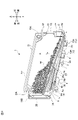
- Fig. 1 is a perspective view of the case 1 as viewed obliquely from above.
- the case 1 accommodates therein an electronic component 50 (shown in FIG. 2) as a component in a loose state.
- Case 1 is detachably set in feeder 100 .
- the feeder 100 is a device that ejects the electronic component 50 from the case 1 by vibrating and supplies the electronic component 50 to a mounting device (not shown).
- the electronic component 50 of the present embodiment is, for example, a minute rectangular parallelepiped electronic component with a length of 1.2 mm or less in the longitudinal direction.
- Such electronic components include capacitors, inductors, and the like, but the present embodiment is not limited to these.
- FIG. 2 and 3 are perspective views showing the internal state of the case 1 from which the second member 22, which will be described later, is removed.
- 2 shows a state in which the opening 6 for ejecting the electronic component 50 is open
- FIG. 3 shows a state in which the opening 6 is closed.
- FIG. 4 is a perspective view of the case 1 viewed obliquely from below.
- the case 1 includes a case body 2, a shutter member 3, a slider 4 integrated with the shutter member 3, and an RFID tag 5.
- the case body 2 has a first member 21 and a second member 22 .
- the case 1 is a container in which a housing space S is formed inside by combining and joining a first member 21 and a second member 22 .
- the case body 2 includes a top plate portion 2U, a bottom plate portion 2D, a front wall portion 2F, a rear wall portion 2B, a right side wall portion 2R on the first member 21 side, and a left side wall portion 2L on the second member 22 side. And prepare.
- the vertical direction of the case 1 when the case 1 is set on the feeder 100 is defined as the vertical direction of the case 1 .
- the side of the case 1 where the opening 6 is provided is the front side, and the opposite side is the rear side.
- the horizontal directions such as the left side and the right side are the horizontal directions when the case 1 is viewed from the front.
- the first member 21 is on the right side and the second member 22 is on the left side.
- Each of the front wall portion 2F, the rear wall portion 2B, the right wall portion 2R, and the left wall portion 2L is a wall portion extending in the vertical direction, that is, in the up-down direction.
- Each of the top plate portion 2U and the bottom plate portion 2D is a plate portion extending in the horizontal direction.
- the case 1 is configured by combining a first member 21 and a second member 22 which are bilaterally symmetrical and joined together. That is, each of the first member 21 and the second member 22 is a half-split body divided into left and right.
- the case body 2 has an opening 6 on the lower side of the front wall portion 2F.
- the opening 6 is rectangular in the embodiment. Note that the opening 6 is not limited to a rectangular shape, and may be an opening having a contour such as a circle or an ellipse.
- the plate member 7 extends between the first member 21 and the second member 22 in the accommodation space S.
- the upper surface of the plate member 7 extends from the rear toward the lower edge 6a of the opening 6 in the front, forming an inclined surface 7a inclined so that the lower edge 6a side is the lowest.
- the inclination angle .theta. of the inclined surface 7a is preferably 3.degree.
- the shutter member 3 that opens and closes the opening 6 extends continuously from the bottom plate portion 2D to the front wall portion 2F.
- the shutter member 3 opens and closes the opening 6 by sliding along its own extending direction.
- the shutter member 3 extends continuously from the bottom plate portion 2D to the front wall portion 2F, and is slidable along its extending direction.
- the shutter member 3 is an elongate strip-shaped film member.
- the shutter member 3 is made of a flexible material that has some rigidity and can be bent, such as PET (Polyethylene terephthalate).
- the width of the shutter member 3 is slightly larger than the width of the opening 6 and has a width capable of covering the opening 6 without any gap.
- the shutter member 3 has an opening 3a having substantially the same shape as the opening 6 at its front end. When the opening 3a and the opening 6 match, the opening 6 opens. When the shutter member 3 covers the opening 6 , the opening 6 is closed by the shutter member 3 .
- the opening 3a need not have the same shape as the opening 6, and may have a shape and size that allows the opening 6 to open.
- a concave portion 61 recessed from the outside to the inside of the case body 2 is provided above the opening 6 in the front wall portion 2F of the case body 2 .
- a pair of left and right guide grooves 62 extending in the vertical direction are provided on the side surfaces of the case 1 in the thickness direction, ie, the left-right direction, at the portion where the opening 6 and the recess 61 are provided. Both side portions extending in the longitudinal direction of the shutter member 3 are inserted into the left and right guide grooves 62 respectively. The shutter member 3 is guided by the guide groove 62 and slides vertically on the front wall portion 2F.
- the rear end of the shutter member 3 is provided with a circular hole 3b.
- a slider 4 is attached integrally with the shutter member 3 using the hole 3b.
- the slider 4 is a rectangular parallelepiped member, and as shown in FIG. 4, has a lower opening 4c that opens downward, and has a front end plate portion 4d and a rear end plate portion 4e.
- the slider 4 has a flange portion 4a extending in the left-right direction at its upper end.
- the slider 4 has a convex portion 4b on its upper surface.
- the protrusion 4b is fitted into the hole 3b of the shutter member 3 and protrudes upward, whereby the slider 4 is integrated with the shutter member 3.
- FIG. 1 shows that the slider 4 has a flange portion 4a extending in the left-right direction at its upper end.
- the slider 4 has a convex portion 4b on its upper surface.
- the protrusion 4b is fitted into the hole 3b of the shutter member 3 and protrudes upward, whereby the slider 4 is integrated with the shutter member 3.
- the bottom plate portion 2D of the case 1 is provided with a concave portion 23 that is recessed upward and elongated in the front-rear direction.
- a slit 24 is provided on the front surface of the recess 23 .
- a rear end portion of the shutter member 3 is inserted through the slit 24 .
- the rear end of the shutter member 3 extends along the bottom surface of the recess 23 through the slit 24 .
- a pair of front and rear recesses 26a and 26b are provided on the lower surface of the recess 23.
- the convex portion 4b of the slider 4 can be fitted into each of the recesses 26a and 26b.
- Groove portions 25 extending in the front-rear direction are provided on both sides of the bottom plate portion 2D in the left-right direction where the recess portions 23 are provided.
- Left and right flange portions 4a of the slider 4 are inserted into the left and right groove portions 25, respectively.
- the sliding range of the slider 4 is between the position where the protrusion 4b engages with the front recess 26a and the position where it engages with the rear recess 26b.
- the opening 3a of the shutter member 3 is positioned within the recess 61 and does not match the opening 6. As shown in FIG. At this time, the entire opening 6 is closed by the shutter member 3 and the electronic component 50 is not ejected from the opening 6 to the outside.
- the shutter member 3 slides rearward and the projection 4b fits into the recess 26b on the rear side as shown in FIG. At this time, the opening 6 is opened and the electronic component 50 can be ejected from the opening 6 .
- the case body 2 has an upper grip portion 10A and a rear grip portion 10B.
- the upper grip portion 10A is a pair of front and rear depressions provided at both front and rear ends of the upper side of the case body 2 .
- the rear gripping portions 10B are a pair of upper and lower depressions provided at both upper and lower ends of the rear side of the case body 2 .
- Each of the upper gripping portion 10A and the rear gripping portion 10B is gripped by the robot hand, for example, when the case 1 is transported by the robot hand.
- a through hole 9 penetrating left and right is provided at a lower portion of the case body 2 and at a position generally corresponding to the recess 23 .
- the through hole 9 is a slit-shaped hole extending in the front-rear direction.
- a strip-shaped RFID tag 5 extending in the front-rear direction is attached to the upper surface inside the through-hole 9 .
- the RFID tag 5 has a known configuration including a transmitter/receiver, memory, antenna, and the like.
- the feeder 100 is provided with a reader/writer 105 that reads and writes information with respect to the RFID tag 5 .
- the case body 2 further has a claw portion 8 and a T-slot portion 13 extending downward from the outer surface of the bottom plate portion 2D.
- the claw portion 8 includes a front claw portion 8A and a rear claw portion 8B.
- the front side claw portion 8A and the rear side claw portion 8B are plate pieces having the same shape, extending downward from above and having an L-shape in side view with the lower end bent rearward by approximately 90°. Note that the front claw portion 8A and the rear claw portion 8B may not have the same shape.
- the T-slot portion 13 includes a front T-slot portion 13A and a rear T-slot portion 13B. Both the front T-slot portion 13A and the rear T-slot portion 13B are protrusions that are inverted T-shaped when viewed from the front.
- the front T-slot portion 13A has a tapered portion 13c formed at the front end thereof.
- the feeder 100 has an engaging portion (not shown) that enables the case 1 to be set in the feeder 100 by detachably engaging the claw portion 8 and the T-slot portion 13 .
- the claw portion 8 and the T-slot portion 13 are engaged with the engaging portion, respectively, so that the case 1 is detachably set on the feeder 100 .
- the feeder 100 vibrates with the opening 6 open, whereby the electronic components 50 are discharged from the opening 6 along the inclined surface 7a.
- the ejected electronic component 50 is supplied to the mounting apparatus as described above.
- FIG. 5 is a plan view showing an outline of the component storage device 200
- FIG. 6 is a partial cross-sectional view corresponding to line VI-VI in FIG.
- the component storage device 200 is a device that automatically stores a plurality of electronic components 50 in the storage space S through the opening 6 inside the case 1 described above.
- the component storage device 200 includes a first transport unit 210, a first discharge unit 230 for discharging the electronic components 50 from the first transport unit 210, and a case 1.
- a second conveying unit 310 that conveys the electronic component 50 from the first discharging unit 230 to the vicinity of the case 1 installed in the installing unit 240; a second ejecting unit 330 for ejecting the electronic component 50 into the case 1 installed in the housing;
- the first transport section 210 continuously transports the plurality of electronic components 50 to the first discharge section 230 .
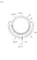
- the first conveying unit 210 of the embodiment includes a linear feeder 211 that linearly and continuously conveys a plurality of electronic components 50 , receives the plurality of components conveyed by the linear feeder 211 one by one, and rotates to rotate the electronic components 50 . and a turntable 212 for rotating and intermittently conveying the component 50 .
- a plurality of electronic components 50 are conveyed toward a turntable 212 in a row by a linear feeder 211 installed substantially horizontally.
- the linear feeder 211 is vibrated by, for example, a vibrator (not shown), and the vibration sequentially conveys the electronic components 50 toward the turntable 212 in the arrow F direction.
- the electronic component 50 is fed on the linear feeder 211 while being pushed by the following electronic component 50 .
- the linear feeder 211 extends toward the center of rotation of the turntable 212 and its terminal end reaches near the outer periphery of the turntable 212 .
- the turntable 212 is a disc-shaped rotating member that is installed horizontally.
- the turntable 212 is made of ceramic, glass epoxy resin, or the like.
- the turntable 212 is rotatably arranged on the base 214 via a rotating shaft 213 extending in the vertical direction.
- the turntable 212 is intermittently rotated in the direction of arrow R in FIG.
- a plurality of cutouts 215 opening to the outer peripheral side are arranged at equal intervals in the circumferential direction on the outer peripheral edge of the turntable 212 .
- One electronic component 50 is accommodated inside one notch 215 .
- the rotation direction of the turntable 212 is not limited to the R direction in FIG. 5, and may be the reverse direction of the R direction.
- the turntable 212 is arranged on the top surface 216 of the base 214 .
- the notch 215 is open on the outer peripheral surface side and upper and lower surfaces of the turntable 212 .
- the turntable 212 has air suction passages (not shown) communicating with the cutouts 215 therein.
- the air suction passage is open on the inner surface of each notch 215 .
- the air suction passage communicates with a suction source such as a vacuum pump, and when this suction source operates, the air in the notch 215 is sucked to the back side surface to create a negative pressure state.
- a suction source such as a vacuum pump
- the electronic components 50 conveyed to the vicinity of the turntable 212 by the linear feeder 211 are accommodated one by one from the side in each of the plurality of notches 215 of the intermittently rotating turntable 212, It is held by being adsorbed to the surface.
- the electronic components 50 accommodated and held in the notches 215 are intermittently transported to the first discharge section 230 in the direction of the arrow R by the rotation of the turntable 212 .
- the electronic component 50 accommodated in the notch 215 moves on the top surface 216 of the base 214 .
- the first discharge section 230 is arranged corresponding to the turntable 212 .
- the first discharge unit 230 is arranged on a circular conveying path corresponding to the rotation trajectory of the notch 215 of the turntable 212 .
- the first discharge section 230 is arranged at a rotational angular position of approximately 270° with respect to the transition from the linear feeder 211 to the turntable 212 .
- the first ejecting section 230 is a section that drops the electronic components 50 conveyed by the turntable 212 one by one onto the second conveying section 310 under their own weight and ejects them.
- the first discharge section 230 may be arranged at any position on the conveying path of the turntable 212 .
- it may be arranged at the farthest position when viewed from the linear feeder 211 , that is, at a rotational angle position of 180° with respect to the transition portion from the linear feeder 211 to the turntable 212 .
- the electronic component 50 ejected from the first ejecting section 230 is conveyed by the second conveying section 310 .
- the electronic component 50 conveyed by the second conveying section 310 is discharged from the second discharging section 330 so as to be accommodated in the case 1 installed in the installation section 240 .
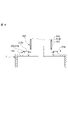
- the case 1 is installed on the installation portion 240 as shown in FIGS. 7 to 9. FIG.
- the case 1 is installed in the installation section 240 in such a state that the electronic components 50 ejected from the first ejection section 230 are positioned to drop into the opening 6 .
- the case 1 is installed on the installation portion 240 in a state in which the front-rear direction of the case 1 is along the vertical direction, that is, in a vertically placed state.
- the installation portion 240 includes a wall portion 241, a holding portion 250 that holds the case 1 vertically on the wall portion 241, an opening/closing mechanism 260 that opens and closes the shutter member 3 of the case 1, have
- the wall portion 241 has a wall surface 241a that is a surface along the substantially vertical direction.
- the holding portion 250 includes a pair of upper and lower hook portions projecting from the wall surface 241a, that is, an upper hook portion 251 and a lower hook portion 252 .
- the upper hook portion 251 and the lower hook portion 252 are plate pieces having the same shape, and having an L-shape in side view with the tip bent upward by approximately 90°.
- the front claw portion 8A of the case 1 is detachably engaged with the upper hook portion 251 from above
- the rear claw portion 8B of the case 1 is detachably engaged with the lower hook portion 252 from above. match.
- the case 1 is detachably held by the holding portion 250 .
- the upper hook portion 251 and the lower hook portion 252 may not have the same shape.
- the wall portion 241 is formed with a recess 242 that extends vertically and opens toward the wall surface 241a.
- An opening/closing mechanism 260 for sliding the shutter member 3 is arranged in the recess 242 .
- the opening/closing mechanism 260 has a drive pin 261 that is vertically movable along the bottom surface of the recess 242 .
- a tip portion of the driving pin 261 protrudes from the wall surface 241a.
- the drive pin 261 is supported vertically movably along, for example, a guide groove provided on the bottom surface of the recess 242, and driven to reciprocate vertically by an actuator or the like.
- a reader/writer 243 capable of writing information to the RFID tag 5 without contact is arranged in the recess 242 of the wall portion 241 .
- the drive pin 261 is engaged with the slider 4 of the case 1 held by the holding portion 250 .
- the shutter member 3 of the case 1 shown in FIG. 8 slides forward (upward in FIG. 8) so that the protrusion 4b of the slider 4 is fitted into the front recess 26a, and the opening 6 is closed by the shutter member 3. ing.
- the drive pin 261 has moved upward.
- the drive pin 261 moves toward the lower opening of the slider 4 shown in FIG. It is inserted into the portion 4c and positioned between the front end plate portion 4d and the rear end plate portion 4e.
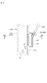
- the second conveying section 310 is arranged from below the first discharge section 230 to above the case 1 installed in the installation section 240 .
- the first ejector 230 includes a passage hole 218 provided in the base 214 and a push pin 236 .
- the first discharge section 230 is provided with a suction release mechanism (not shown) that releases the suction and holding of the electronic component 50 by air suction into the notch 215 .
- the suction canceling mechanism for example, there is a mechanism that ejects air to stop or weaken the flow of the sucked air.
- the passage hole 218 is arranged at a position directly below the outer peripheral edge of the turntable 212 and at a position corresponding to the notch 215 of the turntable 212 .
- Passing hole 218 has a size through which electronic component 50 passes.
- the introduction port 311 of the second conveying section 310 is arranged.
- the push pin 236 has a function of forcibly dropping the electronic component 50 from the notch 215 .
- a hold down pin 236 is positioned above the notch 215 in line with the through hole 218 .
- the push pin 236 is a rod-shaped member that extends vertically, and is driven vertically by an actuator (not shown) or the like.
- the push pin 236 is driven downward, the electronic component 50 in the notch 215 is pushed downward and dropped through the passage hole 218 onto the second transport section 310 .
- the electronic component 50 reliably falls out of the notch 215 without being caught in the notch 215 .
- the first discharge section 230 may be provided with an air flow generating section 237 that causes the electronic component 50 to drop from the notch 215 by air flow.
- an air flow generating section 237 for example, one having a function of blowing air from above to drop the electronic component 50, or sucking air from the side to drop the electronic component 50, or the like. is mentioned.
- the first discharge section 230 is provided with a cleaning section 238 that cleans the path of the electronic component 50 passing through the first discharge section 230 .
- the cleaning unit 238 is arranged above the push pin 236 and is composed of an air suction mechanism for sucking air. Air is drawn in by the cleaning section 238 , so that the air in the notch 215 , the passage hole 218 , and the conveying path of the electronic components 50 inside the second conveying section 310 is sucked. As a result, fragments, dust, etc. present in the path are sucked into the cleaning section 238 and cleaned.
- the cleaning unit 238 may clean the path of the electronic component 50 by ejecting air to blow away fragments, dust, and the like. In this case, in order to prevent debris, dust, etc. from entering the case 1, it is preferable to operate the shutter member 3 with the opening 6 closed.
- the second discharge section 330 includes the distal end 312 of the second transport section 310 .
- the end portion 312 extends vertically.
- the electronic component 50 that has passed through the terminal portion 312 drops into the opening 6 of the case 1 installed in the installation portion 240 and is accommodated in the case 1 .
- the component detection unit 270 detects the electronic component 50 at any position on the path of the electronic component 50 from the first transport unit 210 to the opening 6 of the case 1 installed in the installation unit 240 .
- the component detection unit 270 of the embodiment includes a first component detection unit 271 arranged at a predetermined position on the side of the linear feeder 211 shown in FIG. It includes a third component detection section 273 and a fourth component detection section 274 provided below the second ejection section 330 shown in FIG.
- the first component detection unit 271 detects the electronic component 50 conveyed by the linear feeder 211 at a fixed position.
- the second component detector 272 is arranged on the upstream side of the conveying path of the turntable 212 .
- the third component detection section 273 is arranged downstream of the second component detection section 272 in the conveying path of the turntable 212 .
- the first component detection unit 271 has a counter function as a passage detection unit that detects, for example, the passage of the electronic component 50 and counts the number of passages of the electronic component 50 .
- the second component detection unit 272 is, for example, an image sensor as a shape detection unit that detects the shape of the electronic component 50 and detects whether or not the electronic component 50 has a shape defect from the detected shape.
- the third component detector 273 functions as a performance detector that detects the performance of the electronic component 50, for example. For example, when the electronic component 50 is a capacitor, a capacitance sensor or the like that detects whether or not the capacitance as a function has a specified value is applied to the performance detection unit.
- the fourth component detection unit 274 includes an upstream passage detection unit 275 arranged on the upstream side of the second conveying unit 310 shown in FIG. and a downstream passage detector 276 .
- the upstream passage detector 275 has a function of a counter that counts the number of electronic components 50 that pass through the passage hole 218 and drop into the introduction port 311 of the second transporter 310 .
- the upstream passage detector 275 uses a known optical sensor composed of a light emitting element 275a and a light receiving element 275b.
- the lower passage detector 276 has a function of a counter that counts the number of electronic components 50 that pass through the end portion 312 of the second ejector 330 and enter the opening 6 of the case 1 .
- the downstream passage detection section 276 is similar to the upstream passage detection section 275, and a known optical sensor composed of a light emitting element 276a and a light receiving element 276b is used.
- the optical sensor may be of a type that receives the reflection of the emitted light from the object, and the light-emitting element and the light-receiving element may be integrated without being separated.
- the second conveying section 310 includes a tubular member 313 arranged between the first ejection section 230 and the second ejection section 330 .
- the tubular member 313 forms a transport path connecting the first discharge section 230 and the case 1 installed in the installation section 240 .
- the tubular member 313 is arranged below the turntable 212 .
- the tubular member 313 is a tube having a circular cross section and is made of resin or metal.
- the electronic component 50 is conveyed while falling inside the tubular member 313 according to gravity.
- tubular member 313 is made of resin, it is preferable that all or part of it is made of a transparent or translucent material. As a result, the electronic component 50 being transported inside the tubular member 313 can be visually recognized from the outside through the transparent or translucent portion, and the transport status can be confirmed.
- tubular member 313 has an upstream end 313A and a downstream end 313E, and a first intermediate portion 313B between upstream end 313A and downstream end 313E. , a second intermediate portion 313C and a third intermediate portion 313D.
- the upstream end 313A and the downstream end 313E extend substantially vertically.
- the first intermediate portion 313B and the third intermediate portion 313D are inclined at a predetermined angle so as to become downwardly inclined from above to below.
- the second intermediate portion 313C extends substantially horizontally.
- tubular member 313 has a second intermediate portion 313C extending substantially horizontally, the tubular member 313 as a whole extends continuously in the vertical direction from the upstream end portion 313A to the downstream end portion 313E while being bent at a plurality of points.
- the tubular member 313 of the embodiment that constitutes the second conveying unit 310 has a straight shape in plan view, but the tubular member 313 may have a shape that bends or curves even in plan view.
- the straight portions of the second conveying portion 310 are the first intermediate portion 313B, the second intermediate portion 313C, and the third intermediate portion 313D.
- the tubular member 313 is arranged so as not to interfere with various devices installed around the turntable 212 and the base 214 .
- the upstream end 313A has the introduction port 311 described above at its upper end.
- the introduction port 311 is formed in an inverted conical shape with an inner diameter increasing upward.
- the inner diameter of the circular upper opening edge of inlet 311 is sufficiently larger than electronic component 50 .
- the introduction port 311 is located close to the passage hole 218 and directly below the passage hole 218 .
- the electronic component 50 dropping through the passage hole 218 is guided to pass through the introduction port 311 and drop into the tubular member 313 .
- the electronic component 50 slides down to the second discharge portion 330 while contacting the inner surface of the tubular member 313 .
- the tubular member 313 has a substantially uniform inner diameter except for the introduction port 311, and the inner diameter is sufficiently longer than the longest diagonal length of the electronic component 50, for example, about 2 to 40 times.
- the downstream end 313E has the above-described distal end 312 opening downward at its lower end.
- the end portion 312 is arranged so as to be close to the opening 6 of the case 1 installed on the installation portion 240 and to be positioned directly above the opening 6 . As a result, the electronic component 50 falling through the end portion 312 enters the case 1 through the opening 6 .
- the second conveying section 310 of the embodiment includes a plurality of conveying force applying sections 320 that apply a conveying force to the electronic components 50 conveyed on the second conveying section 310 , and a conveying auxiliary section 370 . and have The conveying force imparting portion 320 is arranged in each of the upstream end portion 313A, the first intermediate portion 313B, the second intermediate portion 313C and the third intermediate portion 313D.
- the conveying assistance portion 370 is arranged at the downstream end portion 313E.
- Examples of the conveying force imparting unit 320 of the embodiment include a first compressed air supply mechanism 340 shown in FIGS. 13 and 14 and a vibration imparting mechanism 350 shown in FIG. A second compressed air supply mechanism 360 shown in FIG.
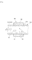
- the first compressed air supply mechanism 340 shown in FIGS. 13 and 14 includes a first porous portion 331 provided on a portion of the tube wall 314 of the tubular member 313, and a cover covering the first porous portion 331. 332 and a nozzle 333 for supplying compressed air into the cover 332 .
- the first compressed air supply mechanism 340 shown in FIGS. 13 and 14 is provided at the upstream end 313A.
- the first porous portion 331 is a portion having a semicircular cross-section that occupies approximately half of the length of the tube wall 314 in the circumferential direction, and is provided integrally with the tube wall 314 .
- the first porous portion 331 has a large number of pores.
- the cover 332 covers the first porous portion 331 and is airtightly joined to the outer peripheral surface of the pipe wall 314 .
- the nozzle 333 is connected to a compressed air supply source (not shown) and joined to the cover 332 so as to be able to supply compressed air into the cover 332 . Compressed air is supplied into the cover 332 through the nozzle 333 from the compressed air supply source.
- Compressed air supplied from the nozzle 333 into the cover 332 passes through the pores of the first porous portion 331 and is blown into the tubular member 313 .
- the tip of the nozzle 333 is joined to the cover 332 in an inclined state so as to face downward, that is, in the conveying direction of the electronic component 50 .
- the electronic component 50 being transported inside the tubular member 313 receives the compressed air and is given a transporting force so as to propel the electronic component 50 downward in the transport direction.
- the cover 332 functions to prevent air from escaping from the first porous portion 331 to the outside of the tubular member 313 .
- first compressed air supply mechanism 340 is not limited to the upstream end 313A, and may be any of the first intermediate portion 313B, the second intermediate portion 313C, the third intermediate portion 313D and the downstream end 313E. One or all may be provided.
- the vibration imparting mechanism 350 shown in FIG. 15 is provided in the second intermediate portion 313C extending substantially horizontally.
- the vibration applying mechanism 350 includes a piezoelectric mechanism 351 as a vibration source arranged on the outer peripheral portion of the tube wall 314 of the tubular member 313 .
- the piezoelectric mechanism 351 causes the tube wall 314 of the tubular member 313 to vibrate, and the vibration is transmitted to the electronic component 50 in contact with the inner surface of the tube wall 314, causing the electronic component 50 to move in the conveying direction (arrow H direction in FIG. 15). A propelling transport force is applied.
- the direction of vibration by the piezoelectric mechanism 351 is the direction toward the conveying direction of the electronic component 50, and that the angle ⁇ with respect to the conveying direction is 20° or more and 70° or less.
- the electronic component 50 which is in contact with the inner surface of the lower side of the tube wall 314, is repeatedly floated forward in the conveying direction and then dropped, and vibrations that tend to progress in the conveying direction are generated. receive.
- the vibration imparting mechanism 350 is not limited to the second intermediate portion 313C, but any one of the upstream end portion 313A, the first intermediate portion 313B, the third intermediate portion 313D, and the downstream end portion 313E, or Although it may be provided in all, it is effective to apply it to a horizontal conveying path where stagnation is likely to occur, such as the second intermediate portion 313C. Further, the above-described first compressed air supply mechanism 340 and vibration imparting mechanism 350 may be arranged so as to be appropriately mixed in the second conveying section 310 .
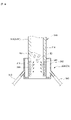
- a second compressed air supply mechanism 360 shown in FIG. 16 is provided at the end portion 312 of the downstream end portion 313E.
- the second compressed air supply mechanism 360 includes a cylindrical second porous portion 341 provided on a part of the pipe wall 314, a cover 342 covering the second porous portion 341, and a cover 342 for supplying the compressed air. and a plurality of nozzles 343 feeding into.
- the second porous portion 341 has a large number of pores like the first porous portion 331, but has a cylindrical shape along the entire circumference.
- the cover 342 covers the second porous portion 341 and is airtightly joined to the outer peripheral surface of the pipe wall 314 .
- the plurality of nozzles 343 are connected to a compressed air supply source (not shown) and joined to the cover 342 so as to supply compressed air into the cover 342 .
- Compressed air is supplied from the compressed air supply source into the cover through a nozzle.
- Compressed air supplied from the nozzle 343 into the cover 342 passes through the pores of the second porous portion 341 and is blown into the tubular member 313 .
- the cover 342 functions to prevent air from escaping from the second porous portion 341 to the outside of the tubular member 313 .
- the tips of the plurality of nozzles 343 are joined to the cover 342 in an inclined state so as to face downward, which is the conveying direction of the electronic component 50, and face upward in the opposite direction.
- the electronic component 50 conveyed inside the end portion 312 is floated by the compressed air blown from the plurality of nozzles 343 .
- the compressed air assists the transportation of the electronic component 50 .
- the second compressed air supply mechanism 360 is arranged at the end portion 312 of the second discharge portion 330, clogging of the electronic components from the second discharge portion 330 is suppressed, which is effective. is.
- the cross-sectional shape of tubular member 313 is not limited to a circular shape.
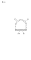
- 17A, 17B, and 17C each show a configuration example of the first porous portion 331 of the first compressed air supply mechanism 340 when the cross section of the tubular member 313 is not circular.
- a tubular member 313 shown in FIG. 17A has a cross-sectional shape in which an arc portion 315a and a straight portion 315b are combined. In this case, the straight portion 315 b is the first porous portion 331 .
- the tubular member 313 shown in FIG. 17B has a rectangular cross-section, and one side portion 316b is the first porous portion 331.
- a tubular member 313 shown in FIG. 17C has a D-shaped cross section in which a substantially horseshoe-shaped deformed portion 317a and a straight portion 317b are combined. In this case, the straight portion 317 b is the first porous portion 331 .
- a component storage device 200 is a component storage device that stores a plurality of electronic components 50 from an opening 6 in a case 1 having an opening 6.
- a second transport section 310 that transports the electronic component 50 to the case 1 installed in the installation section 240, and the electronic component 50 transported by the second transport section 310 is opened in the case 1 installed in the installation section 240. 6
- the second conveying unit 310 has a conveying force that imparts a conveying force to the electronic components 50 conveyed on the second conveying unit 310. It has a granting unit 320 .
- the electronic component 50 conveyed by the second conveying section 310 is less likely to stagnate because the conveying force is applied from the conveying force applying section 320 , and is smoothly conveyed to the case 1 and housed in the case 1 .
- the conveying force applying section 320 preferably applies conveying force to the second conveying section 310 by applying air or vibration to the second conveying section 310 .
- the second conveying section 310 includes a tubular member 313 arranged between the first discharging section 230 and the second discharging section 330, and serves as the conveying force imparting section 320.
- the provided first compressed air supply mechanism 340 includes a first porous portion 331 having a large number of pores provided in at least a portion of the tubular member 313, and the air supplied to the second conveying portion 310 is , compressed air blown into the tubular member 313 from the first porous portion 331 .
- the electronic component 50 can be reliably conveyed to the second discharge section 330 without deviating from the conveying path.
- By blowing compressed air into the tubular member 313 through the first porous portion 331 it is possible to accurately apply the conveying force to the electronic component 50 .
- the conveying force imparting unit 320 includes a piezoelectric mechanism 351 that imparts vibration to the second conveying unit 310, and the vibration imparted to the second conveying unit 310 is generated by the piezoelectric mechanism 351. It is preferably vibration to be applied.
- the direction of vibration by the piezoelectric mechanism 351 is directed toward the conveying direction of the electronic components 50 in the second conveying section 310 and at an angle of 20° or more and 70° or less with respect to the conveying direction. is preferably slanted at .
- the electronic component 50 can be easily conveyed in that portion.
- the second conveying section 310 includes a tubular member 313 arranged between the first discharging section 230 and the second discharging section 330, and the tubular member 313 A terminal portion 312 that drops and conveys the electronic component 50 toward the opening 6 of the case 1 installed in the portion 240, and a second compressed air supply mechanism 360 as a transportation auxiliary portion 370 provided in the terminal portion 312.
- the second compressed air supply mechanism 360 includes a second porous portion 341 having a large number of pores provided in at least a portion of the end portion 312, and the second porous portion 341 to the end portion 312 Compressed air is preferably blown into the interior of the electronic component 50 in a direction opposite to the direction in which the electronic component 50 is conveyed.
- the electronic component 50 is moved in the direction opposite to the conveying direction by the compressed air at the end portion 312 where clogging is likely to occur, and as a result, clogging is less likely to occur.
- the present invention is not limited to the above-described embodiments, and includes modifications, improvements, etc. within the scope of achieving the object of the present invention.
- the tube wall 314 of the tubular member 313 Compressed air may be blown through a large number of holes provided in the tube wall 314, or a nozzle such as the nozzle 333 may be penetrated through the tube wall 314 and the compressed air may be blown directly from the nozzle.
- the second compressed air supply mechanism 360 is also the same.
- the conveying force applied to the electronic component 50 by the conveying force imparting unit 320 is not limited to compressed air or vibration, and any force can be used as long as the electronic component 50 can be actively conveyed by a force other than gravity. It can be.
- First conveying section 210 is not limited to a combination of linear feeder 211 and turntable 212 as long as it can convey electronic components 50 to second conveying section 310 .
- the second conveying portion 310 is not limited to the tubular member 313 as long as the electronic component 50 is conveyed by dropping action due to gravity.
Landscapes
- Engineering & Computer Science (AREA)
- Mechanical Engineering (AREA)
- Physics & Mathematics (AREA)
- Fluid Mechanics (AREA)
- Feeding Of Articles To Conveyors (AREA)
Abstract
Description
図1~図4は、実施形態に係るケース1に関する図である。図5及び図6は、実施形態に係る部品収容装置200に関する図である。部品収容装置200は、ケース1内に複数の部品を自動的に収容する装置である。はじめに、ケース1について説明する。 Embodiments of the present invention will be described below.
1 to 4 are diagrams relating to
前側壁部2F、後側壁部2B、右側壁部2R及び左側壁部2Lのそれぞれは、鉛直方向すなわち上下方向に延びる壁部である。天板部2U及び底板部2Dのそれぞれは、水平方向に延びる板部である。 In this specification, the vertical direction of the
Each of the
図5は部品収容装置200の概要を示す平面図、図6は図5のVI-VI線に対応する一部断面図である。 Next, an overview of the
5 is a plan view showing an outline of the
保持部250は、壁面241aから突出する上下一対のフック部、すなわち上側フック部251と、下側フック部252と、を含む。上側フック部251及び下側フック部252は同形状であって、先端が略90°上方に屈曲した側面視L字形状を有する板片である。図8に示すように、上側フック部251にケース1の前側爪部8Aが上方から着脱可能に係合し、下側フック部252にケース1の後側爪部8Bが上方から着脱可能に係合する。これにより、ケース1は保持部250に着脱可能に保持される。なお、上側フック部251と下側フック部252とは同形状でなくてもよい。 The
The holding
なお、清浄部238は、空気を噴出して破片や塵埃等を吹き飛ばすことにより電子部品50の経路を清浄化するものでもよい。その場合、ケース1内に破片や塵埃等が入り込むことを防ぐために、シャッター部材3により開口6を閉じた状態で作動させるとよい。 Furthermore, the
Note that the
また、上述した第1の圧縮エアー供給機構340と振動付与機構350とを、第2の搬送部310に適宜に混在するように配置してもよい。 Note that the
Further, the above-described first compressed
図17A、図17B及び図17Cのそれぞれは、管状部材313の断面が円形状ではない場合において、上記第1の圧縮エアー供給機構340の第1の多孔質部331の構成例を示している。
図17Aに示す管状部材313は、円弧部315aと直線部315bとが組み合わされた断面形状を有している。この場合、直線部315bが第1の多孔質部331となっている。
図17Bに示す管状部材313は、断面矩形状であって、1つの辺部316bが第1の多孔質部331となっている。
図17Cに示す管状部材313は、略馬蹄形状の異形部317aと直線部317bとが組み合わされた断面D字形状を有している。この場合、直線部317bが第1の多孔質部331となっている。 The cross-sectional shape of
17A, 17B, and 17C each show a configuration example of the first
A
The
A
例えば、第1の圧縮エアー供給機構340における第1の多孔質部331のような多数の気孔を含む多孔質部を通して圧縮エアーを管状部材313の内部に吹き込む代わりに、管状部材313の管壁314に空けた多数の孔から圧縮エアーを吹き込んだり、上記ノズル333のようなノズルを管壁314に貫通させてノズルから直接圧縮エアーを吹き込んだりしてもよい。この点に関しては、第2の圧縮エアー供給機構360も同様である。
搬送力付与部320が電子部品50に付与する搬送力としては、圧縮エアーや振動に限定されず、電子部品50を重力以外の力で能動的に搬送することができるものであればいかなるものであってよい。
第1の搬送部210は、第2の搬送部310まで電子部品50を搬送できるものであれば、リニアフィーダ211とターンテーブル212との組み合わせに限定されない。
第2の搬送部310は、重力による落下作用で電子部品50が搬送されるものであれば管状部材313に限定されず、例えば傾斜した樋状部材や板部材等であってもよい。 Although the embodiments have been described above, the present invention is not limited to the above-described embodiments, and includes modifications, improvements, etc. within the scope of achieving the object of the present invention.
For example, instead of blowing compressed air into the interior of the
The conveying force applied to the
First conveying
The second conveying
6 開口
50 電子部品(部品)
200 部品収容装置
210 第1の搬送部
230 第1の排出部
240 設置部
310 第2の搬送部
312 末端部
313 管状部材
320 搬送力付与部
330 第2の排出部
331 第1の多孔質部
340 第1の圧縮エアー供給機構(搬送力付与部)
341 第2の多孔質部
350 振動付与機構(搬送力付与部)
351 圧電機構
360 第2の圧縮エアー供給機構(搬送補助部)
370 搬送補助部 1
200
341 second
351
370 Conveying Auxiliary Section
Claims (6)
- 開口を有するケース内に複数の部品を前記開口から収容する部品収容装置であって、
複数の部品を搬送する第1の搬送部と、
前記第1の搬送部により搬送された部品を排出する第1の排出部と、
前記ケースが設置される設置部と、
前記第1の排出部から排出される部品を前記設置部に設置された前記ケースに搬送する第2の搬送部と、
前記第2の搬送部により搬送された部品を前記設置部に設置された前記ケース内に前記開口から収容されるように排出する第2の排出部と、を備え、
前記第2の搬送部は、当該第2の搬送部を搬送される部品に搬送力を付与する搬送力付与部を有する、部品収容装置。 A component housing device for housing a plurality of components in a case having an opening through the opening,
a first transport unit that transports a plurality of parts;
a first discharge unit that discharges the components transported by the first transport unit;
an installation portion on which the case is installed;
a second conveying unit that conveys the components discharged from the first discharging unit to the case installed in the installation unit;
a second discharge unit that discharges the components conveyed by the second conveying unit so as to be accommodated from the opening in the case installed in the installation unit;
The component storage device, wherein the second transport unit has a transport force imparting unit that imparts a transport force to the components transported through the second transport unit. - 前記搬送力付与部は、前記第2の搬送部にエアーもしくは振動を付与することによって前記第2の搬送部に搬送力を付与する、請求項1に記載の部品収容装置。 The component storage device according to claim 1, wherein the conveying force imparting unit imparts the conveying force to the second conveying unit by applying air or vibration to the second conveying unit.
- 前記第2の搬送部は、前記第1の排出部と前記第2の排出部との間に配置された管状部材を含み、
前記搬送力付与部は、前記管状部材の少なくとも一部に設けられた多数の気孔を有する第1の多孔質部を含み、
前記エアーは、前記第1の多孔質部から前記管状部材の内部に吹き込まれる圧縮エアーである、請求項2に記載の部品収容装置。 the second transport section includes a tubular member disposed between the first discharge section and the second discharge section;
The conveying force applying section includes a first porous section having a large number of pores provided in at least a portion of the tubular member,
3. The component storage device according to claim 2, wherein said air is compressed air blown into said tubular member from said first porous portion. - 前記搬送力付与部は、前記第2の搬送部に振動を付与する圧電機構を含み、前記振動は、前記圧電機構が付与する振動である請求項2に記載の部品収容装置。 3. The component storage device according to claim 2, wherein the conveying force imparting section includes a piezoelectric mechanism that imparts vibration to the second conveying section, and the vibration is vibration imparted by the piezoelectric mechanism.
- 前記圧電機構による振動の方向は、前記第2の搬送部における部品の搬送方向に向かい、かつその搬送方向に対して20°以上70°以下の角度で傾斜している、請求項4に記載の部品収容装置。 5. The method according to claim 4, wherein the direction of vibration by the piezoelectric mechanism is directed toward the conveying direction of the components in the second conveying unit and is inclined at an angle of 20° or more and 70° or less with respect to the conveying direction. Parts storage device.
- 前記第2の搬送部は、前記第1の排出部と前記第2の排出部との間に配置された管状部材を含み、
前記管状部材は、前記設置部に設置される前記ケースの前記開口に向かって部品を落下させて搬送する末端部と、前記末端部に設けられた搬送補助部と、を有し、
前記搬送補助部は、前記末端部の少なくとも一部に設けられた多数の気孔を有する第2の多孔質部を含み、前記第2の多孔質部から前記末端部の内部に部品の搬送方向に対向する方向に圧縮エアーが吹き込まれる、請求項1~5のいずれか1項に記載の部品収容装置。 the second transport section includes a tubular member disposed between the first discharge section and the second discharge section;
The tubular member has an end portion for dropping and transporting the component toward the opening of the case installed in the installation portion, and a transport auxiliary portion provided at the end portion,
The conveying assisting part includes a second porous part having a large number of pores provided in at least a part of the end part, and the part is conveyed from the second porous part to the inside of the end part in the conveying direction of the component. 6. The component storage device according to any one of claims 1 to 5, wherein compressed air is blown in opposite directions.
Priority Applications (3)
| Application Number | Priority Date | Filing Date | Title |
|---|---|---|---|
| CN202280045560.1A CN117580788A (en) | 2021-07-07 | 2022-05-23 | Component housing device |
| KR1020247000471A KR20240018599A (en) | 2021-07-07 | 2022-05-23 | Parts receiving device |
| JP2023533459A JPWO2023281927A1 (en) | 2021-07-07 | 2022-05-23 |
Applications Claiming Priority (2)
| Application Number | Priority Date | Filing Date | Title |
|---|---|---|---|
| JP2021113063 | 2021-07-07 | ||
| JP2021-113063 | 2021-07-07 |
Publications (1)
| Publication Number | Publication Date |
|---|---|
| WO2023281927A1 true WO2023281927A1 (en) | 2023-01-12 |
Family
ID=84800563
Family Applications (1)
| Application Number | Title | Priority Date | Filing Date |
|---|---|---|---|
| PCT/JP2022/021108 WO2023281927A1 (en) | 2021-07-07 | 2022-05-23 | Component accommodation device |
Country Status (4)
| Country | Link |
|---|---|
| JP (1) | JPWO2023281927A1 (en) |
| KR (1) | KR20240018599A (en) |
| CN (1) | CN117580788A (en) |
| WO (1) | WO2023281927A1 (en) |
Citations (7)
| Publication number | Priority date | Publication date | Assignee | Title |
|---|---|---|---|---|
| JPS5535063U (en) * | 1978-08-30 | 1980-03-06 | ||
| JPH07109018A (en) * | 1993-10-13 | 1995-04-25 | Printing Bureau Ministry Of Finance Japan | Powder carrying chute equipment having porous inner tube |
| JPH08204386A (en) * | 1995-01-23 | 1996-08-09 | Murata Mfg Co Ltd | Chip parts arranging and feeding apparatus |
| JP2000191126A (en) * | 1998-12-24 | 2000-07-11 | Seratekku:Kk | Piezoelectric-driven type carrying device |
| JP2001503002A (en) * | 1996-10-30 | 2001-03-06 | ブリティッシュ アメリカン タバコ(インヴェストメンツ)リミテッド | How to transport tobacco |
| JP2002045159A (en) * | 2000-08-04 | 2002-02-12 | Mitsubishi Heavy Ind Ltd | Electron beam sterilization device |
| JP2010023435A (en) * | 2008-07-24 | 2010-02-04 | Matsui Mfg Co | Granular material supply device, granular material supply system equipped with this device, and granular material supply method using this device |
Family Cites Families (1)
| Publication number | Priority date | Publication date | Assignee | Title |
|---|---|---|---|---|
| JP5054616B2 (en) | 2008-06-02 | 2012-10-24 | 太陽誘電株式会社 | Parts replenishment system for bulk feeder |
-
2022
- 2022-05-23 KR KR1020247000471A patent/KR20240018599A/en unknown
- 2022-05-23 CN CN202280045560.1A patent/CN117580788A/en active Pending
- 2022-05-23 WO PCT/JP2022/021108 patent/WO2023281927A1/en active Application Filing
- 2022-05-23 JP JP2023533459A patent/JPWO2023281927A1/ja active Pending
Patent Citations (7)
| Publication number | Priority date | Publication date | Assignee | Title |
|---|---|---|---|---|
| JPS5535063U (en) * | 1978-08-30 | 1980-03-06 | ||
| JPH07109018A (en) * | 1993-10-13 | 1995-04-25 | Printing Bureau Ministry Of Finance Japan | Powder carrying chute equipment having porous inner tube |
| JPH08204386A (en) * | 1995-01-23 | 1996-08-09 | Murata Mfg Co Ltd | Chip parts arranging and feeding apparatus |
| JP2001503002A (en) * | 1996-10-30 | 2001-03-06 | ブリティッシュ アメリカン タバコ(インヴェストメンツ)リミテッド | How to transport tobacco |
| JP2000191126A (en) * | 1998-12-24 | 2000-07-11 | Seratekku:Kk | Piezoelectric-driven type carrying device |
| JP2002045159A (en) * | 2000-08-04 | 2002-02-12 | Mitsubishi Heavy Ind Ltd | Electron beam sterilization device |
| JP2010023435A (en) * | 2008-07-24 | 2010-02-04 | Matsui Mfg Co | Granular material supply device, granular material supply system equipped with this device, and granular material supply method using this device |
Also Published As
| Publication number | Publication date |
|---|---|
| CN117580788A (en) | 2024-02-20 |
| KR20240018599A (en) | 2024-02-13 |
| JPWO2023281927A1 (en) | 2023-01-12 |
Similar Documents
| Publication | Publication Date | Title |
|---|---|---|
| JP2023171527A (en) | Component storage device | |
| JP6093429B1 (en) | Capillary transport device, capillary mounting device, capillary exchange device, capillary transport method, capillary mounting method and capillary replacement method | |
| TW201103849A (en) | Workpiece inserting mechanism and workpiece inserting method | |
| TWI657027B (en) | Article supply device | |
| JP7405111B2 (en) | Parts storage equipment and production management system | |
| WO2023281927A1 (en) | Component accommodation device | |
| JP7435515B2 (en) | Parts storage device | |
| TWI330050B (en) | ||
| JP7415996B2 (en) | Parts storage device | |
| JP7400762B2 (en) | Parts storage device | |
| JP2001187634A (en) | Automatic work feeding device | |
| JP6730322B2 (en) | Article supplying method and apparatus | |
| JP3200612B2 (en) | Method and apparatus for storing polarized chip parts | |
| JP3278385B2 (en) | Chip component supply device | |
| KR101545852B1 (en) | Standby at vibration chute and non-vibration unloading type parts feeder | |
| JP2003057015A (en) | Visual examination device for minute part and method for using the same |
Legal Events
| Date | Code | Title | Description |
|---|---|---|---|
| 121 | Ep: the epo has been informed by wipo that ep was designated in this application |
Ref document number: 22837348 Country of ref document: EP Kind code of ref document: A1 |
|
| WWE | Wipo information: entry into national phase |
Ref document number: 2023533459 Country of ref document: JP |
|
| ENP | Entry into the national phase |
Ref document number: 20247000471 Country of ref document: KR Kind code of ref document: A |
|
| WWE | Wipo information: entry into national phase |
Ref document number: 1020247000471 Country of ref document: KR |
|
| NENP | Non-entry into the national phase |
Ref country code: DE |