WO2022181383A1 - Cylindrical battery and manufacturing method for same - Google Patents
Cylindrical battery and manufacturing method for same Download PDFInfo
- Publication number
- WO2022181383A1 WO2022181383A1 PCT/JP2022/005823 JP2022005823W WO2022181383A1 WO 2022181383 A1 WO2022181383 A1 WO 2022181383A1 JP 2022005823 W JP2022005823 W JP 2022005823W WO 2022181383 A1 WO2022181383 A1 WO 2022181383A1
- Authority
- WO
- WIPO (PCT)
- Prior art keywords
- negative electrode
- cylindrical battery
- electrode lead
- metal plate
- lead portions
- Prior art date
Links
- 238000004519 manufacturing process Methods 0.000 title claims description 6
- 229910052751 metal Inorganic materials 0.000 claims abstract description 64
- 239000002184 metal Substances 0.000 claims abstract description 63
- 239000011888 foil Substances 0.000 claims description 9
- 238000000034 method Methods 0.000 claims description 5
- 230000001678 irradiating effect Effects 0.000 claims description 4
- 238000007789 sealing Methods 0.000 description 22
- 239000000203 mixture Substances 0.000 description 18
- 238000003466 welding Methods 0.000 description 18
- 238000010586 diagram Methods 0.000 description 16
- 239000010410 layer Substances 0.000 description 16
- 238000004804 winding Methods 0.000 description 13
- 239000011255 nonaqueous electrolyte Substances 0.000 description 9
- OKTJSMMVPCPJKN-UHFFFAOYSA-N Carbon Chemical group [C] OKTJSMMVPCPJKN-UHFFFAOYSA-N 0.000 description 8
- 239000011230 binding agent Substances 0.000 description 8
- 230000004048 modification Effects 0.000 description 7
- 238000012986 modification Methods 0.000 description 7
- 239000007773 negative electrode material Substances 0.000 description 7
- RYGMFSIKBFXOCR-UHFFFAOYSA-N Copper Chemical compound [Cu] RYGMFSIKBFXOCR-UHFFFAOYSA-N 0.000 description 6
- PXHVJJICTQNCMI-UHFFFAOYSA-N nickel Substances [Ni] PXHVJJICTQNCMI-UHFFFAOYSA-N 0.000 description 6
- -1 polytetrafluoroethylene Polymers 0.000 description 6
- WHXSMMKQMYFTQS-UHFFFAOYSA-N Lithium Chemical group [Li] WHXSMMKQMYFTQS-UHFFFAOYSA-N 0.000 description 5
- 239000003792 electrolyte Substances 0.000 description 5
- 239000010408 film Substances 0.000 description 5
- 229910002804 graphite Inorganic materials 0.000 description 5
- 239000010439 graphite Substances 0.000 description 5
- 229910052744 lithium Inorganic materials 0.000 description 5
- 239000007774 positive electrode material Substances 0.000 description 5
- 150000003839 salts Chemical class 0.000 description 5
- 239000002033 PVDF binder Substances 0.000 description 4
- 229910052782 aluminium Inorganic materials 0.000 description 4
- 239000003125 aqueous solvent Substances 0.000 description 4
- 239000006258 conductive agent Substances 0.000 description 4
- 239000000470 constituent Substances 0.000 description 4
- 229910052802 copper Inorganic materials 0.000 description 4
- 239000010949 copper Substances 0.000 description 4
- 239000000463 material Substances 0.000 description 4
- 229910052759 nickel Inorganic materials 0.000 description 4
- 230000002093 peripheral effect Effects 0.000 description 4
- 229920005672 polyolefin resin Polymers 0.000 description 4
- 229920002981 polyvinylidene fluoride Polymers 0.000 description 4
- 229920002134 Carboxymethyl cellulose Polymers 0.000 description 3
- 230000004323 axial length Effects 0.000 description 3
- 239000003575 carbonaceous material Substances 0.000 description 3
- 239000011248 coating agent Substances 0.000 description 3
- 238000000576 coating method Methods 0.000 description 3
- 239000011889 copper foil Substances 0.000 description 3
- XEEYBQQBJWHFJM-UHFFFAOYSA-N iron Substances [Fe] XEEYBQQBJWHFJM-UHFFFAOYSA-N 0.000 description 3
- 238000005304 joining Methods 0.000 description 3
- 239000002905 metal composite material Substances 0.000 description 3
- 229920002239 polyacrylonitrile Polymers 0.000 description 3
- 238000002360 preparation method Methods 0.000 description 3
- 238000004080 punching Methods 0.000 description 3
- 239000004925 Acrylic resin Substances 0.000 description 2
- 229920000178 Acrylic resin Polymers 0.000 description 2
- OIFBSDVPJOWBCH-UHFFFAOYSA-N Diethyl carbonate Chemical compound CCOC(=O)OCC OIFBSDVPJOWBCH-UHFFFAOYSA-N 0.000 description 2
- KMTRUDSVKNLOMY-UHFFFAOYSA-N Ethylene carbonate Chemical compound O=C1OCCO1 KMTRUDSVKNLOMY-UHFFFAOYSA-N 0.000 description 2
- 229910013870 LiPF 6 Inorganic materials 0.000 description 2
- HBBGRARXTFLTSG-UHFFFAOYSA-N Lithium ion Chemical compound [Li+] HBBGRARXTFLTSG-UHFFFAOYSA-N 0.000 description 2
- 229920003171 Poly (ethylene oxide) Polymers 0.000 description 2
- 239000006230 acetylene black Substances 0.000 description 2
- 229910045601 alloy Inorganic materials 0.000 description 2
- 239000000956 alloy Substances 0.000 description 2
- XAGFODPZIPBFFR-UHFFFAOYSA-N aluminium Chemical compound [Al] XAGFODPZIPBFFR-UHFFFAOYSA-N 0.000 description 2
- 229910021383 artificial graphite Inorganic materials 0.000 description 2
- 239000001768 carboxy methyl cellulose Substances 0.000 description 2
- 235000010948 carboxy methyl cellulose Nutrition 0.000 description 2
- 239000008112 carboxymethyl-cellulose Substances 0.000 description 2
- 229920002678 cellulose Polymers 0.000 description 2
- 239000001913 cellulose Substances 0.000 description 2
- 230000000694 effects Effects 0.000 description 2
- 239000002003 electrode paste Substances 0.000 description 2
- JBTWLSYIZRCDFO-UHFFFAOYSA-N ethyl methyl carbonate Chemical compound CCOC(=O)OC JBTWLSYIZRCDFO-UHFFFAOYSA-N 0.000 description 2
- 229910052742 iron Inorganic materials 0.000 description 2
- 229910001416 lithium ion Inorganic materials 0.000 description 2
- 229910052748 manganese Inorganic materials 0.000 description 2
- 239000012046 mixed solvent Substances 0.000 description 2
- 229920001721 polyimide Polymers 0.000 description 2
- 239000009719 polyimide resin Substances 0.000 description 2
- 229920001343 polytetrafluoroethylene Polymers 0.000 description 2
- 239000004810 polytetrafluoroethylene Substances 0.000 description 2
- 230000008569 process Effects 0.000 description 2
- 229920005989 resin Polymers 0.000 description 2
- 239000011347 resin Substances 0.000 description 2
- 239000002002 slurry Substances 0.000 description 2
- 229920003048 styrene butadiene rubber Polymers 0.000 description 2
- 239000002344 surface layer Substances 0.000 description 2
- 229910000838 Al alloy Inorganic materials 0.000 description 1
- 229910001018 Cast iron Inorganic materials 0.000 description 1
- 229910000881 Cu alloy Inorganic materials 0.000 description 1
- PXGOKWXKJXAPGV-UHFFFAOYSA-N Fluorine Chemical compound FF PXGOKWXKJXAPGV-UHFFFAOYSA-N 0.000 description 1
- 229910002995 LiNi0.8Co0.15Al0.05O2 Inorganic materials 0.000 description 1
- 239000004698 Polyethylene Substances 0.000 description 1
- 239000004743 Polypropylene Substances 0.000 description 1
- 239000004372 Polyvinyl alcohol Substances 0.000 description 1
- XUIMIQQOPSSXEZ-UHFFFAOYSA-N Silicon Chemical compound [Si] XUIMIQQOPSSXEZ-UHFFFAOYSA-N 0.000 description 1
- 229920002125 Sokalan® Polymers 0.000 description 1
- 239000002174 Styrene-butadiene Substances 0.000 description 1
- 150000001408 amides Chemical class 0.000 description 1
- 229910052796 boron Inorganic materials 0.000 description 1
- QHIWVLPBUQWDMQ-UHFFFAOYSA-N butyl prop-2-enoate;methyl 2-methylprop-2-enoate;prop-2-enoic acid Chemical compound OC(=O)C=C.COC(=O)C(C)=C.CCCCOC(=O)C=C QHIWVLPBUQWDMQ-UHFFFAOYSA-N 0.000 description 1
- 229910052799 carbon Inorganic materials 0.000 description 1
- 229910052804 chromium Inorganic materials 0.000 description 1
- 239000011651 chromium Substances 0.000 description 1
- 239000002131 composite material Substances 0.000 description 1
- 150000001875 compounds Chemical class 0.000 description 1
- 238000005520 cutting process Methods 0.000 description 1
- 230000008021 deposition Effects 0.000 description 1
- 239000008151 electrolyte solution Substances 0.000 description 1
- 150000002148 esters Chemical class 0.000 description 1
- 150000002170 ethers Chemical class 0.000 description 1
- 229910052731 fluorine Inorganic materials 0.000 description 1
- 239000011737 fluorine Substances 0.000 description 1
- 229910021469 graphitizable carbon Inorganic materials 0.000 description 1
- 125000005843 halogen group Chemical group 0.000 description 1
- 125000004435 hydrogen atom Chemical group [H]* 0.000 description 1
- 229910052738 indium Inorganic materials 0.000 description 1
- 239000011810 insulating material Substances 0.000 description 1
- 238000009413 insulation Methods 0.000 description 1
- 230000010220 ion permeability Effects 0.000 description 1
- 239000003273 ketjen black Substances 0.000 description 1
- 239000007788 liquid Substances 0.000 description 1
- 239000011244 liquid electrolyte Substances 0.000 description 1
- 229910003002 lithium salt Inorganic materials 0.000 description 1
- 159000000002 lithium salts Chemical class 0.000 description 1
- 229910052749 magnesium Inorganic materials 0.000 description 1
- 150000002739 metals Chemical class 0.000 description 1
- 239000011325 microbead Substances 0.000 description 1
- 229910021382 natural graphite Inorganic materials 0.000 description 1
- 229910052758 niobium Inorganic materials 0.000 description 1
- 150000002825 nitriles Chemical class 0.000 description 1
- 239000004745 nonwoven fabric Substances 0.000 description 1
- 229920000573 polyethylene Polymers 0.000 description 1
- 229920000642 polymer Polymers 0.000 description 1
- 229920001155 polypropylene Polymers 0.000 description 1
- 229920002451 polyvinyl alcohol Polymers 0.000 description 1
- 239000000565 sealant Substances 0.000 description 1
- 239000003566 sealing material Substances 0.000 description 1
- 229910052710 silicon Inorganic materials 0.000 description 1
- 239000010703 silicon Substances 0.000 description 1
- 239000002356 single layer Substances 0.000 description 1
- 239000007784 solid electrolyte Substances 0.000 description 1
- 239000002904 solvent Substances 0.000 description 1
- 238000009987 spinning Methods 0.000 description 1
- 229910052715 tantalum Inorganic materials 0.000 description 1
- 239000002562 thickening agent Substances 0.000 description 1
- 239000010409 thin film Substances 0.000 description 1
- 229910052718 tin Inorganic materials 0.000 description 1
- 229910052719 titanium Inorganic materials 0.000 description 1
- 229910052721 tungsten Inorganic materials 0.000 description 1
- 229910052720 vanadium Inorganic materials 0.000 description 1
- XLYOFNOQVPJJNP-UHFFFAOYSA-N water Substances O XLYOFNOQVPJJNP-UHFFFAOYSA-N 0.000 description 1
- 239000002759 woven fabric Substances 0.000 description 1
- 229910052725 zinc Inorganic materials 0.000 description 1
- 239000011701 zinc Substances 0.000 description 1
- 229910052726 zirconium Inorganic materials 0.000 description 1
Images


Classifications
-
- H—ELECTRICITY
- H01—ELECTRIC ELEMENTS
- H01M—PROCESSES OR MEANS, e.g. BATTERIES, FOR THE DIRECT CONVERSION OF CHEMICAL ENERGY INTO ELECTRICAL ENERGY
- H01M50/00—Constructional details or processes of manufacture of the non-active parts of electrochemical cells other than fuel cells, e.g. hybrid cells
- H01M50/10—Primary casings; Jackets or wrappings
- H01M50/102—Primary casings; Jackets or wrappings characterised by their shape or physical structure
- H01M50/107—Primary casings; Jackets or wrappings characterised by their shape or physical structure having curved cross-section, e.g. round or elliptic
-
- H—ELECTRICITY
- H01—ELECTRIC ELEMENTS
- H01M—PROCESSES OR MEANS, e.g. BATTERIES, FOR THE DIRECT CONVERSION OF CHEMICAL ENERGY INTO ELECTRICAL ENERGY
- H01M50/00—Constructional details or processes of manufacture of the non-active parts of electrochemical cells other than fuel cells, e.g. hybrid cells
- H01M50/50—Current conducting connections for cells or batteries
- H01M50/531—Electrode connections inside a battery casing
- H01M50/533—Electrode connections inside a battery casing characterised by the shape of the leads or tabs
-
- H—ELECTRICITY
- H01—ELECTRIC ELEMENTS
- H01M—PROCESSES OR MEANS, e.g. BATTERIES, FOR THE DIRECT CONVERSION OF CHEMICAL ENERGY INTO ELECTRICAL ENERGY
- H01M50/00—Constructional details or processes of manufacture of the non-active parts of electrochemical cells other than fuel cells, e.g. hybrid cells
- H01M50/50—Current conducting connections for cells or batteries
- H01M50/531—Electrode connections inside a battery casing
- H01M50/534—Electrode connections inside a battery casing characterised by the material of the leads or tabs
-
- H—ELECTRICITY
- H01—ELECTRIC ELEMENTS
- H01M—PROCESSES OR MEANS, e.g. BATTERIES, FOR THE DIRECT CONVERSION OF CHEMICAL ENERGY INTO ELECTRICAL ENERGY
- H01M50/00—Constructional details or processes of manufacture of the non-active parts of electrochemical cells other than fuel cells, e.g. hybrid cells
- H01M50/50—Current conducting connections for cells or batteries
- H01M50/531—Electrode connections inside a battery casing
- H01M50/538—Connection of several leads or tabs of wound or folded electrode stacks
-
- H—ELECTRICITY
- H01—ELECTRIC ELEMENTS
- H01M—PROCESSES OR MEANS, e.g. BATTERIES, FOR THE DIRECT CONVERSION OF CHEMICAL ENERGY INTO ELECTRICAL ENERGY
- H01M50/00—Constructional details or processes of manufacture of the non-active parts of electrochemical cells other than fuel cells, e.g. hybrid cells
- H01M50/50—Current conducting connections for cells or batteries
- H01M50/543—Terminals
- H01M50/545—Terminals formed by the casing of the cells
-
- H—ELECTRICITY
- H01—ELECTRIC ELEMENTS
- H01M—PROCESSES OR MEANS, e.g. BATTERIES, FOR THE DIRECT CONVERSION OF CHEMICAL ENERGY INTO ELECTRICAL ENERGY
- H01M50/00—Constructional details or processes of manufacture of the non-active parts of electrochemical cells other than fuel cells, e.g. hybrid cells
- H01M50/50—Current conducting connections for cells or batteries
- H01M50/543—Terminals
- H01M50/547—Terminals characterised by the disposition of the terminals on the cells
- H01M50/548—Terminals characterised by the disposition of the terminals on the cells on opposite sides of the cell
-
- H—ELECTRICITY
- H01—ELECTRIC ELEMENTS
- H01M—PROCESSES OR MEANS, e.g. BATTERIES, FOR THE DIRECT CONVERSION OF CHEMICAL ENERGY INTO ELECTRICAL ENERGY
- H01M50/00—Constructional details or processes of manufacture of the non-active parts of electrochemical cells other than fuel cells, e.g. hybrid cells
- H01M50/50—Current conducting connections for cells or batteries
- H01M50/543—Terminals
- H01M50/564—Terminals characterised by their manufacturing process
- H01M50/566—Terminals characterised by their manufacturing process by welding, soldering or brazing
-
- H—ELECTRICITY
- H01—ELECTRIC ELEMENTS
- H01M—PROCESSES OR MEANS, e.g. BATTERIES, FOR THE DIRECT CONVERSION OF CHEMICAL ENERGY INTO ELECTRICAL ENERGY
- H01M50/00—Constructional details or processes of manufacture of the non-active parts of electrochemical cells other than fuel cells, e.g. hybrid cells
- H01M50/50—Current conducting connections for cells or batteries
- H01M50/572—Means for preventing undesired use or discharge
- H01M50/584—Means for preventing undesired use or discharge for preventing incorrect connections inside or outside the batteries
- H01M50/586—Means for preventing undesired use or discharge for preventing incorrect connections inside or outside the batteries inside the batteries, e.g. incorrect connections of electrodes
-
- H—ELECTRICITY
- H01—ELECTRIC ELEMENTS
- H01M—PROCESSES OR MEANS, e.g. BATTERIES, FOR THE DIRECT CONVERSION OF CHEMICAL ENERGY INTO ELECTRICAL ENERGY
- H01M10/00—Secondary cells; Manufacture thereof
- H01M10/04—Construction or manufacture in general
- H01M10/0431—Cells with wound or folded electrodes
-
- H—ELECTRICITY
- H01—ELECTRIC ELEMENTS
- H01M—PROCESSES OR MEANS, e.g. BATTERIES, FOR THE DIRECT CONVERSION OF CHEMICAL ENERGY INTO ELECTRICAL ENERGY
- H01M10/00—Secondary cells; Manufacture thereof
- H01M10/05—Accumulators with non-aqueous electrolyte
- H01M10/058—Construction or manufacture
- H01M10/0587—Construction or manufacture of accumulators having only wound construction elements, i.e. wound positive electrodes, wound negative electrodes and wound separators
-
- Y—GENERAL TAGGING OF NEW TECHNOLOGICAL DEVELOPMENTS; GENERAL TAGGING OF CROSS-SECTIONAL TECHNOLOGIES SPANNING OVER SEVERAL SECTIONS OF THE IPC; TECHNICAL SUBJECTS COVERED BY FORMER USPC CROSS-REFERENCE ART COLLECTIONS [XRACs] AND DIGESTS
- Y02—TECHNOLOGIES OR APPLICATIONS FOR MITIGATION OR ADAPTATION AGAINST CLIMATE CHANGE
- Y02E—REDUCTION OF GREENHOUSE GAS [GHG] EMISSIONS, RELATED TO ENERGY GENERATION, TRANSMISSION OR DISTRIBUTION
- Y02E60/00—Enabling technologies; Technologies with a potential or indirect contribution to GHG emissions mitigation
- Y02E60/10—Energy storage using batteries
-
- Y—GENERAL TAGGING OF NEW TECHNOLOGICAL DEVELOPMENTS; GENERAL TAGGING OF CROSS-SECTIONAL TECHNOLOGIES SPANNING OVER SEVERAL SECTIONS OF THE IPC; TECHNICAL SUBJECTS COVERED BY FORMER USPC CROSS-REFERENCE ART COLLECTIONS [XRACs] AND DIGESTS
- Y02—TECHNOLOGIES OR APPLICATIONS FOR MITIGATION OR ADAPTATION AGAINST CLIMATE CHANGE
- Y02P—CLIMATE CHANGE MITIGATION TECHNOLOGIES IN THE PRODUCTION OR PROCESSING OF GOODS
- Y02P70/00—Climate change mitigation technologies in the production process for final industrial or consumer products
- Y02P70/50—Manufacturing or production processes characterised by the final manufactured product
Definitions
- the present disclosure relates to cylindrical batteries and manufacturing methods thereof.
- Patent Document 1 there is one described in Patent Document 1 as a cylindrical battery.
- This cylindrical battery includes a negative electrode current collector arranged between an electrode assembly and an outer can.
- a plurality of negative electrode leads protruding from the negative electrode of the electrode body are welded to the surface of the negative electrode current collector on the electrode body side.
- the negative electrode current collector is electrically connected to the outer can. connected to.
- an object of the present disclosure is to provide a cylindrical battery capable of reducing internal resistance.
- the cylindrical battery according to the present disclosure includes a bottomed cylindrical outer can, and a long first electrode and a long second electrode that are housed in the outer can and have different polarities.
- the plurality of second electrode lead portions can be electrically connected to the outer can without interposing the metal plate, the internal resistance can be reduced.
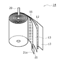
- FIG. 1 is an axial cross-sectional view of a cylindrical battery according to an embodiment of the present disclosure
- FIG. 3 is a perspective view of an electrode body
- FIG. It is a schematic plan view when a negative electrode is seen from the thickness direction.
- FIG. 4 is a schematic diagram showing the position of the negative electrode lead and the irradiation area of the laser light when the cylindrical battery of the example is viewed from the bottom of the outer can.
- FIG. 2 is a schematic diagram showing the bottom side of the cylindrical battery of FIG. 1
- FIG. 5B is a schematic diagram corresponding to FIG. 5A in the cylindrical battery of the second embodiment
- FIG. 5B is a schematic diagram corresponding to FIG. 5A in the cylindrical battery of the third embodiment
- FIG. 5B is a schematic diagram corresponding to FIG.
- FIG. 5A in the cylindrical battery of the fourth embodiment; It is a schematic diagram corresponding to FIG. 4 explaining the irradiation area
- FIG. 5 is a schematic diagram corresponding to FIG. 4 for explaining a laser beam irradiation region of another modified example;
- FIG. 5 is a schematic diagram corresponding to FIG. 4 for explaining a laser beam irradiation region of another modified example;
- FIG. 4 is a schematic plan view corresponding to FIG. 3 in a negative electrode of a modified example;
- the cylindrical battery of the present disclosure may be a primary battery or a secondary battery.
- a battery using an aqueous electrolyte or a battery using a non-aqueous electrolyte may be used.
- a non-aqueous electrolyte secondary battery (lithium ion battery) using a non-aqueous electrolyte is exemplified below as the cylindrical battery 10 of one embodiment, but the cylindrical battery of the present disclosure is not limited to this.
- FIG. 1 is an axial cross-sectional view of a cylindrical battery 10 according to an embodiment of the present disclosure
- FIG. 2 is a perspective view of an electrode body 14 of the cylindrical battery 10.
- a cylindrical battery 10 includes a wound electrode assembly 14, a non-aqueous electrolyte (not shown), and a battery case 15 that accommodates the electrode assembly 14 and the non-aqueous electrolyte.
- the electrode assembly 14 includes a positive electrode 11 as an example of a first electrode, a negative electrode 12 as an example of a second electrode, and a separator 13 interposed between the positive electrode 11 and the negative electrode 12 .
- the electrode body 14 has a wound structure in which the positive electrode 11 and the negative electrode 12 are wound with the separator 13 interposed therebetween.
- the battery case 15 is composed of a bottomed cylindrical outer can 16 and a sealing member 17 that closes the opening of the outer can 16 .
- Cylindrical battery 10 also includes a resin gasket 28 arranged between outer can 16 and sealing member 17 .
- the non-aqueous electrolyte contains a non-aqueous solvent and an electrolyte salt dissolved in the non-aqueous solvent.
- the non-aqueous solvent include esters, ethers, nitriles, amides, and mixed solvents of two or more thereof.
- the non-aqueous solvent may contain a halogen-substituted product obtained by substituting at least part of the hydrogen atoms of these solvents with halogen atoms such as fluorine.
- the non-aqueous electrolyte is not limited to a liquid electrolyte, and may be a solid electrolyte using a gel polymer or the like.
- a lithium salt such as LiPF 6 is used as the electrolyte salt.
- the electrode body 14 has an elongated positive electrode 11 , an elongated negative electrode 12 , and two elongated separators 13 .
- a positive electrode lead 20 is joined to the positive electrode 11 , and a plurality of negative electrode lead portions 21 (only one is shown in FIG. 2) are electrically connected to the negative electrode 12 .
- the negative electrode lead portion 21 constitutes a second electrode lead portion. The structure of the plurality of negative electrode lead portions 21 will be described later in detail with reference to FIG.
- the negative electrode 12 is formed to be one size larger than the positive electrode 11 and longer than the positive electrode 11 in the longitudinal direction and the width direction (transverse direction) in order to suppress deposition of lithium.
- the two separators 13 are at least one size larger than the positive electrode 11, and are arranged so as to sandwich the positive electrode 11, for example.
- the positive electrode 11 has a positive electrode current collector and positive electrode mixture layers formed on both sides of the positive electrode current collector.
- a metal foil stable in the potential range of the positive electrode 11, such as aluminum or an aluminum alloy, or a film in which the metal is arranged on the surface layer can be used.
- the positive electrode mixture layer contains a positive electrode active material, a conductive agent, and a binder.
- a positive electrode mixture slurry containing a positive electrode active material, a conductive agent, a binder, and the like is applied onto a positive electrode current collector, the coating film is dried, and then compressed to collect a positive electrode mixture layer. It can be produced by forming on both sides of the electric body.
- the positive electrode active material is composed mainly of a lithium-containing metal composite oxide.
- Metal elements contained in the lithium-containing metal composite oxide include Ni, Co, Mn, Al, B, Mg, Ti, V, Cr, Fe, Cu, Zn, Ga, Sr, Zr, Nb, In, Sn , Ta, W, and the like.
- An example of a preferable lithium-containing metal composite oxide is a composite oxide containing at least one of Ni, Co, Mn and Al.
- Carbon materials such as carbon black, acetylene black, ketjen black, and graphite can be exemplified as the conductive agent contained in the positive electrode mixture layer.
- the binder contained in the positive electrode mixture layer include fluororesins such as polytetrafluoroethylene (PTFE) and polyvinylidene fluoride (PVdF), polyacrylonitrile (PAN), polyimide resins, acrylic resins, and polyolefin resins. . These resins may be used in combination with cellulose derivatives such as carboxymethyl cellulose (CMC) or salts thereof, polyethylene oxide (PEO), and the like.
- CMC carboxymethyl cellulose
- PEO polyethylene oxide
- the negative electrode 12 has a negative electrode current collector and negative electrode mixture layers formed on both sides of the negative electrode current collector.
- a metal foil stable in the potential range of the negative electrode 12 such as copper or a copper alloy, or a film in which the metal is arranged on the surface layer can be used.
- the negative electrode mixture layer contains a negative electrode active material and a binder.
- a negative electrode mixture slurry containing a negative electrode active material, a binder, and the like is applied onto a negative electrode current collector, the coating film is dried, and then compressed to form a negative electrode mixture layer on the current collector. It can be produced by forming on both sides.
- a carbon material that reversibly absorbs and releases lithium ions is generally used as the negative electrode active material.
- Preferred carbon materials are graphite such as natural graphite such as flake graphite, massive graphite and earthy graphite, massive artificial graphite and artificial graphite such as graphitized mesophase carbon microbeads.
- the negative electrode mixture layer may contain a Si material containing silicon (Si) as a negative electrode active material.
- a metal other than Si that forms an alloy with lithium, an alloy containing the metal, a compound containing the metal, or the like may be used as the negative electrode active material.
- the binder contained in the negative electrode mixture layer may be fluororesin, PAN, polyimide resin, acrylic resin, polyolefin resin, or the like, but preferably styrene-butadiene rubber (SBR ) or its modified form.
- the negative electrode mixture layer may contain, for example, CMC or its salt, polyacrylic acid (PAA) or its salt, polyvinyl alcohol, etc. in addition to SBR or the like.
- a porous sheet having ion permeability and insulation is used for the separator 13 .
- porous sheets include microporous thin films, woven fabrics, and non-woven fabrics.
- polyolefin resins such as polyethylene and polypropylene, cellulose, and the like are preferable.
- the separator 13 may have either a single layer structure or a laminated structure.
- a heat-resistant layer or the like may be formed on the surface of the separator 13 .
- the negative electrode 12 may constitute the winding start end of the electrode body 14, but in general, the separator 13 extends beyond the winding start side end of the negative electrode 12, and the winding start side end of the separator 13 is the electrode body. 14 winding start end.
- the cylindrical battery 10 includes an insulating plate 18 arranged above the electrode assembly 14 and a metal plate 19 arranged below the electrode assembly 14 .
- a positive electrode lead 20 attached to the positive electrode 11 extends through the through hole of the insulating plate 18 toward the sealing member 17 .
- the positive lead 20 is connected to the lower surface of the terminal plate 23, which is the bottom plate of the sealing member 17, by welding or the like, and the sealing plate 27, which is the top plate of the sealing member 17 electrically connected to the terminal plate 23, serves as a positive electrode terminal.
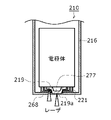
- the plurality of negative electrode lead portions 21 pass through the radially outer side of the metal plate 19 and are then folded back radially inward.
- a tip portion 21 a of each negative electrode lead portion 21 is located between the metal plate 19 and the bottom portion 68 of the outer can 16 .
- the bottom portion 68, the tip portion 21a of each negative electrode lead portion 21, and the metal plate 19 are joined together, and the outer can 16 becomes the negative electrode terminal.
- the outer can 16 is a metal container having a bottomed cylindrical portion.
- the inner space of the battery case 15 is hermetically sealed by sealing the space between the outer can 16 and the sealing member 17 with an annular gasket 28 .
- the gasket 28 is sandwiched between the outer can 16 and the sealing member 17 to insulate the sealing member 17 from the outer can 16 .
- the gasket 28 has a role of a sealing material for keeping the inside of the battery airtight, and a role of an insulating material for insulating the outer can 16 and the sealing body 17 .
- the outer can 16 has an annular grooved portion 35 in a portion of the cylindrical outer peripheral surface in the height direction.
- the grooved portion 35 can be formed, for example, by spinning a portion of the outer peripheral surface of the cylinder radially inward to recess it radially inward.
- the outer can 16 has a bottomed tubular portion 30 including a grooved portion 35 and an annular shoulder portion 33 .
- the bottomed cylindrical portion 30 accommodates the electrode body 14 and the non-aqueous electrolyte, and the shoulder portion 33 is bent radially inward from the opening side end of the bottomed cylindrical portion 30 to extend into the inner side. extending in all directions.
- the shoulder portion 33 is formed when the upper end portion of the outer can 16 is folded inward and crimped to the peripheral edge portion 31 of the sealing member 17 .
- the sealing member 17 is crimped and fixed to the outer can 16 via a gasket 28 between the shoulder portion 33 and the grooved portion 35 .
- a positive electrode mixture paste was prepared by mixing 100 parts by mass of a positive electrode active material, 1.7 parts by mass of polyvinylidene fluoride as a binder, and 2.5 parts by mass of acetylene black as a conductive agent with a liquid component.
- the positive electrode mixture paste was applied to both surfaces of a positive electrode current collector made of aluminum foil, except for the connecting portion of the positive electrode lead, dried, and then rolled to a predetermined thickness to obtain a positive electrode.
- This positive electrode was cut into a predetermined size, and a positive electrode lead made of Al was connected to the exposed portion of the current collector by ultrasonic welding.
- Graphitizable carbon was used as the negative electrode active material. 100 parts by mass of the negative electrode active material, 0.6 parts by mass of polyvinylidene fluoride as a binder, 1 part by mass of carboxymethyl cellulose as a thickening agent, and an appropriate amount of water are stirred with a double-arm kneader. to obtain a negative electrode paste.
- the negative electrode mixture paste was applied to both surfaces of a long negative electrode current collector made of copper foil. When applying the negative electrode paste to both surfaces, a non-application portion was provided in a predetermined region in the width direction of the elongated negative electrode current collector on both sides.
- both surfaces of the negative electrode current collector were dried and then rolled to a predetermined thickness to obtain a negative electrode. Then, it was cut into a predetermined size so that a non-coated portion was formed on one side in the width direction of the negative electrode. After that, the non-applied portion made of copper foil was subjected to a press punching process to form a plurality of negative electrode lead portions 21 made up of part of the non-applied portion.
- FIG. 3 is a schematic plan view of the produced negative electrode 12 when viewed from its thickness direction, and is a schematic plan view for explaining the structure of the negative electrode lead portion 21.
- the edge on the left side of the paper surface is the winding start edge.
- the negative electrode 12 includes a negative electrode current collector 25 and negative electrode mixture layers 26 provided on both sides of the negative electrode current collector 25 .
- the non-applied portion 29 where the negative electrode current collector 25 is exposed is provided on one side in the width direction of both surfaces of the negative electrode 12 .
- a plurality of negative electrode lead portions 21 are formed by a part of the non-applied portion 29 protruding in the width direction of the negative electrode 12 .
- the plurality of negative electrode lead portions 21 are formed of the metal foil (copper foil in this embodiment) that constitutes the negative electrode current collector 25 .
- the plurality of negative electrode lead portions 21 are integrally formed with the negative electrode current collector 25 by the press punching process.
- the plurality of negative electrode lead portions 21 are arranged at intervals in the longitudinal direction of the negative electrode 12 .
- the negative electrode lead portion 21 is not present at the winding start side end in the longitudinal direction, but may be disposed at either the winding start side or the winding end side end in the longitudinal direction.
- the interval (pitch) between two adjacent negative electrode lead portions 21 in the longitudinal direction increases toward the winding end side in the longitudinal direction.
- the length of the negative electrode lead portion 21 increases toward the winding end side in the longitudinal direction. In this way, as shown in FIG. 1, when the negative electrode lead portions 21 are folded radially inward, the tip portions 21a of all the negative electrode lead portions 21 are positioned at approximately the same radial position. I have to.
- the tip 21a of the negative electrode lead portion 21 is welded to the bottom portion 68 of the outer can 16 so that the tip portion 21a of the negative electrode lead portion 21 can be easily aligned during laser welding, which will be described later. At this time, it is not necessary that the tip portions 21 a of all the negative electrode lead portions 21 are joined to the bottom portion 68 of the outer can 16 . If the tip 21 a of at least one of the negative lead portions 21 is joined to the bottom portion 68 of the outer can 16 , the tip portions of all the negative lead portions 21 can be joined by joining the tip portions 21 of the negative lead portions 21 to each other. 21 a can be electrically connected to the bottom of the outer can 16 . Note that the longitudinal interval (pitch) between two adjacent negative electrode lead portions 21 may be the same for two or more pairs of adjacent negative electrode lead portions 21 . Moreover, the plurality of negative electrode lead portions 21 may have two or more negative electrode lead portions having the same length.
- a thin portion 23a (see FIG. 1) is provided in the center of a metal terminal plate 23 that is circular in plan view, and then the terminal plate 23, an annular insulating plate 24 (see FIG. 1), and a sealing plate 27 are integrated. Then, a sealing member 17 was produced. The thin portion 23a is welded to the central portion of the lower surface of the sealing plate 27 .
- the positive electrode 11 and the negative electrode 12 were spirally wound with a separator 13 made of polyolefin resin interposed therebetween to prepare an electrode assembly 14 .
- a metal plate 19 made of nickel was placed on the end surface of the electrode body 14 from which the negative electrode lead portion 21 led out, and the negative electrode lead portion 21 was bent so that the tip portion 21 a was along the lower surface of the metal plate 19 .
- the electrode body 14 was inserted into the outer can 16, and the outer can 16 and the negative electrode lead portion 21 were laser-welded by irradiating a laser beam in the axial direction from the outside of the bottom portion 68 of the outer can 16. .
- Laser welding can be performed under conditions previously used for welding cylindrical batteries.
- the wavelength and intensity of the laser beam used in laser welding can be appropriately changed based on the thickness of the outer can 16 and the like.
- the bottom portion 68 of the outer can 16, the tip portions 21a of the plurality of negative electrode lead portions 21, and the metal plate 19 were joined and integrated.
- the plurality of negative leads 21 are integrated together by laser welding and at least one negative lead 21 is joined to the bottom 68 of the outer can 16 , all of the negative leads 21 are electrically connected to the bottom 68 of the outer can 16 . connected.
- FIG. 4 is a schematic diagram for explaining the position of the negative electrode lead portion 21 and the irradiation area of the laser light when the cylindrical battery 10 is viewed from the bottom portion 68 .
- the shaded area is the area irradiated with the laser light.
- the plurality of negative electrode lead portions 21 are bent radially inward from multiple directions, so that, for example, the four negative electrode lead portions 21 are arranged at the bottom of the can with a slight circumferential gap therebetween. placed on the side.
- the plurality of negative electrode lead portions 21 were radially extended to near the center in the radial direction.
- the irradiation area of the laser beam was circular (point-shaped), and the laser beam was irradiated to a circular area having a radius of a predetermined size centered on the radial center of the outer can 16 .
- the bottom portion 68 of the outer can 16, the plurality of negative electrode lead portions 21, and the metal plate 19 were joined.
- the positive electrode lead 20 connected to the positive electrode 11 and the sealing member 17 were electrically connected by welding.
- the sealing body 17 is inserted into the outer can 16, and the opening end of the outer can 16 and the sealing body 17 are crimped to form the cylindrical battery 10 of the embodiment. was made.
- the cylindrical battery 10 of the present disclosure includes a cylindrical outer can 16 with a bottom and is housed in the outer can 16, and has an elongated positive electrode 11 (first electrode) and an elongated negative electrode 12 (second electrode). and a metal plate 19 arranged between the electrode body 14 and the bottom portion 68 of the outer can 16 .
- Cylindrical battery 10 also includes a plurality of negative electrode lead portions 21 (second electrode lead portions) extending from negative electrode 12 toward bottom portion 68 . Further, the tip portion 21 a of each negative electrode lead portion 21 is sandwiched between the metal plate 19 and the bottom portion 68 and electrically connected to the bottom portion 68 .
- the plurality of negative electrode lead portions 21 are electrically connected to the outer can 16 without interposing the metal plate 19, the resistance loss in the path from the negative electrode 12 to the outer can 16 can be reduced, and the power loss can be reduced. .
- the bonding can be performed reliably.
- the metal plate 19 can be used as a receiver for laser welding. That is, when the negative electrode lead portion 21 and the bottom portion 68 are joined by irradiating laser light from the outside of the can bottom, spatter is generated. Scattering can be substantially suppressed or prevented. Therefore, it is possible to substantially prevent spatter from entering the inside of the electrode body, and a high-quality cylindrical battery 10 can be manufactured.
- the plurality of negative electrode lead portions 21 be made of the same metal foil as the metal foil that constitutes the negative electrode current collector 25 .
- the plurality of negative electrode lead portions 21 can be configured simply and inexpensively.
- At least one of the plurality of negative electrode lead portions 21 is preferably bonded to the metal plate 19 .
- electrical connection between the plurality of negative electrode lead portions 21 and the outer can 16 can be made more reliable.
- the metal plate 19 can be fixed inside the outer can 16 .
- the plurality of negative electrode lead portions 21 and the bottom portion 68 are electrically connected by laser light irradiated from the outside of the outer can 16 .
- the metal plate 19 and the bottom portion 68 of the outer can 16 were not directly joined, but the metal plate and the bottom portion of the outer can may be directly joined.
- FIG. 5A is a schematic diagram showing the bottom 68 side of the cylindrical battery 10.
- FIG. 5B is a schematic diagram corresponding to FIG. 5A in the cylindrical battery 110 of the second embodiment.
- the length of each negative electrode lead portion 121 is slightly shortened so that each negative electrode lead portion 121 can reach only a predetermined area radially inside the metal plate 119. It may not be possible to reach the central portion.
- a projecting portion 119a projecting downward may be provided below the central portion of the metal plate 119 at the radial central portion that the negative electrode lead portions 121 cannot reach.
- the projecting portion 119a and the bottom portion 68 of the outer can 16 may be laser-welded with a laser beam irradiated from the lower side of the outer can 16. As shown in FIG. With this configuration, the bottom portion 68 and the metal plate 119 can be reliably joined, and the electrical connection between the plurality of negative electrode lead portions 121 and the outer can 16 can be further ensured. Also, the positioning of the metal plate 119 in the outer can 16 can be reliably performed.
- each negative electrode lead portion 221 may not reach the radial center portion.
- a protruding portion 219 a protruding downward may be provided below the central portion of the metal plate 219 .
- a concave portion 277 having a shape corresponding to the shape of the projecting portion 219a may be provided on the inner surface of the bottom portion 268 of the outer can 216, and the projecting portion 219a may be fitted into the concave portion 277.
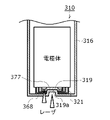
- each negative electrode lead portion 321 may not reach the center portion in the radial direction.
- a concave portion 319 a that is recessed upward may be provided below the central portion of the metal plate 319 .
- a convex portion 377 having a shape corresponding to the shape of the concave portion 319a may be provided on the inner surface of the bottom portion 368 of the outer can 316, and the convex portion 377 may be fitted into the concave portion 319a.
- the metal plates 219, 319 and the bottoms 268, 368 of the outer cans 216, 316 are formed with uneven shapes, the contact between the metal plates 219, 319 and the bottoms 268, 368 can be enhanced. . Therefore, the welding stability can be further improved, and the metal plates 219 and 319 can be precisely positioned.
- FIG. 6A is a schematic diagram corresponding to FIG. 4 for explaining a laser beam irradiation area of a modification
- FIGS. 6B and 6C correspond to FIG. 4 for explaining a laser beam irradiation area of another modification. It is a schematic diagram.
- the hatched areas are laser light irradiation areas.
- laser welding may be performed by irradiating a laser beam from the outside of the can bottom so as to draw a ring shape.
- the plurality of negative electrode lead portions 421 may be bent only in one direction and irradiated with laser light.
- laser light irradiation regions may be provided at a plurality of positions corresponding to the positions where the plurality of negative electrode lead portions 521 are bent.
- the plurality of negative electrode lead portions 21 were integrally formed with the negative electrode current collector 25 by press-punching a metal foil.
- the plurality of negative electrode lead portions may be formed by cutting a metal foil using laser light.
- a plurality of negative electrode lead portions 621 may be formed by joining a plurality of metal (for example, copper) lead plates.
- the welding of the bottom portion 68 of the outer can 16 was performed using laser welding, but the welding of the bottom portion of the outer can may be performed by resistance welding or ultrasonic welding.
- nickel is used as the material of the metal plate 19
- other metals such as cast iron, copper, and nickel-plated iron may be used as the material of the metal plate.
- the axial length of the separator 13 is longer than the axial length of the positive electrode 11 and the axial length of the negative electrode 12. Therefore, even if the metal plate 19 is placed under the electrode body 14 , the separator 13 does not interfere with the short circuit between the positive electrode 11 and the negative electrode 12 through the metal plate 19 .
- an insulating layer is arranged between the metal plate 19 and the electrode body 14 . Examples of insulating layers include insulating plates, insulating tapes, and insulating coating films.
- the negative electrode lead portion also protrude from the winding start side in the longitudinal direction of the negative electrode.
- the negative electrode lead portion formed on the winding start side in the longitudinal direction of the negative electrode is, for example, folded radially outward along the upper surface of the metal plate, and then radially along the lower surface of the metal plate. Folding inward allows electrical connection with the bottom of the outer can.
- a through hole may be provided in the metal plate at a position overlapping the hollow portion of the electrode body in the axial direction. Then, one or more negative electrode lead portions protruding from the winding start side in the longitudinal direction of the negative electrode may be passed through the through hole of the metal plate and then welded to the bottom portion of the outer can.
- the case where the second electrode electrically connected to the outer can 16 is the negative electrode has been described.
- the first electrode may be the negative electrode and the second electrode may be the positive electrode.
- the outer can becomes the positive terminal.
Landscapes
- Chemical & Material Sciences (AREA)
- Chemical Kinetics & Catalysis (AREA)
- Electrochemistry (AREA)
- General Chemical & Material Sciences (AREA)
- Engineering & Computer Science (AREA)
- Manufacturing & Machinery (AREA)
- Connection Of Batteries Or Terminals (AREA)
- Secondary Cells (AREA)
- Sealing Battery Cases Or Jackets (AREA)
Abstract
Description
次に、上記円筒形電池10の作製方法の一例について具体的に説明する。
<正極の作製>
正極活物質としてLiNi0.8Co0.15Al0.05O2を使用した。正極活物質100質量部、結着剤としてポリフッ化ビニリデン1.7質量部、及び導電剤としてアセチレンブラック2.5質量部を、液状成分に混合させて、正極合剤ペーストを調製した。その正極合剤ペーストを、アルミニウム箔からなる正極集電体の両面に、正極リードの接続部分を除いて塗布、乾燥し、その後、所定の厚みに圧延することで、正極を得た。この正極を所定の寸法に裁断し、集電体の露出部にAl製の正極リードを超音波溶着により接続した。 [Cylindrical Battery of Example]
Next, an example of a method for manufacturing the
<Preparation of positive electrode>
LiNi 0.8 Co 0.15 Al 0.05 O 2 was used as a positive electrode active material. A positive electrode mixture paste was prepared by mixing 100 parts by mass of a positive electrode active material, 1.7 parts by mass of polyvinylidene fluoride as a binder, and 2.5 parts by mass of acetylene black as a conductive agent with a liquid component. The positive electrode mixture paste was applied to both surfaces of a positive electrode current collector made of aluminum foil, except for the connecting portion of the positive electrode lead, dried, and then rolled to a predetermined thickness to obtain a positive electrode. This positive electrode was cut into a predetermined size, and a positive electrode lead made of Al was connected to the exposed portion of the current collector by ultrasonic welding.
負極活物質として易黒鉛化炭素を使用した。負極活物質100質量部と、結着剤としてポリフッ化ビニリデン0.6質量部と、増粘剤としてカルボキシメチルセロース1質量部と、適量の水とを、双腕式練合機にて攪拌し、負極ペーストを得た。その負極合剤ペーストを、銅箔からなる長尺状の負極集電体の両面に塗布した。この両面への塗布を行う際、両側で長尺状の負極集電体の幅方向の所定領域に負極ペーストを塗布しない非塗布部を設けた。続けて、負極集電体の両面を乾燥し、その後、所定の厚みに圧延することで負極を得た。そして、負極の幅方向の一方側に非塗布部が形成されるように所定の寸法に裁断した。その後、銅箔で構成される非塗布部にプレス打ち抜き加工を施して、非塗布部の一部で構成される複数の負極リード部21を形成した。 <Production of negative electrode>
Graphitizable carbon was used as the negative electrode active material. 100 parts by mass of the negative electrode active material, 0.6 parts by mass of polyvinylidene fluoride as a binder, 1 part by mass of carboxymethyl cellulose as a thickening agent, and an appropriate amount of water are stirred with a double-arm kneader. to obtain a negative electrode paste. The negative electrode mixture paste was applied to both surfaces of a long negative electrode current collector made of copper foil. When applying the negative electrode paste to both surfaces, a non-application portion was provided in a predetermined region in the width direction of the elongated negative electrode current collector on both sides. Subsequently, both surfaces of the negative electrode current collector were dried and then rolled to a predetermined thickness to obtain a negative electrode. Then, it was cut into a predetermined size so that a non-coated portion was formed on one side in the width direction of the negative electrode. After that, the non-applied portion made of copper foil was subjected to a press punching process to form a plurality of negative
エチレンカーボネート(EC)、ジエチルカーボネート(DEC)、およびエチルメチルカーボネート(EMC)の混合溶媒に、電解質としてヘキサフルオロリン酸リチウム(LiPF6)が1.0mol/Lになるように溶解し、非水電解液を調製した。 <Preparation of non-aqueous electrolyte>
In a mixed solvent of ethylene carbonate (EC), diethyl carbonate (DEC), and ethylmethyl carbonate (EMC), lithium hexafluorophosphate (LiPF 6 ) as an electrolyte was dissolved to a concentration of 1.0 mol/L. An electrolyte was prepared.
平面視が円形の金属製の端子板23の中央部に薄肉部23a(図1参照)を設け、その後、端子板23、環状の絶縁板24(図1参照)、及び封口板27を統合して、封口体17を作製した。薄肉部23aは、封口板27の下面の中央部に溶接により接合した。 <Preparation of the sealant>
A
正極11と負極12を、ポリオレフィン系樹脂製のセパレータ13を介して渦巻状に巻回し、電極体14を作製した。そして、負極リード部21が導出する電極体14の端面にニッケル製の金属板19を配置し、先端部21aが金属板19の下面に沿うように負極リード部21を折り曲げた。続いて、外装缶16の中に電極体14を挿入して、外装缶16の底部68の外方から軸方向にレーザ光を照射して外装缶16と負極リード部21のレーザ溶接を行った。レーザ溶接は、円筒形電池の溶接で従前に用いられている条件で行うことができる。レーザ溶接で用いるレーザ光の波長や強度は、外装缶16の厚さ等に基づいて適宜変更することができる。このレーザ溶接で、外装缶16の底部68、複数の負極リード部21の先端部21a、及び金属板19を接合して、一体に統合した。このとき、全ての負極リード部21の先端部21aが外装缶16の底部68に直接接合されている必要はない。複数の負極リード21がレーザ溶接により一体に統合され、かつ、少なくとも1つの負極リード21が外装缶16の底部68に接合されていれば、全ての負極リード21が外装缶16の底部68に電気的に接続される。 <Battery assembly>
The
本開示の円筒形電池10は、有底筒状の外装缶16と、外装缶16内に収容され、長尺状の正極11(第1電極)と長尺状の負極12(第2電極)とがセパレータ13を介して巻回された電極体14と、外装缶16の底部68と電極体14の間に配置された金属板19を備える。また、円筒形電池10は、負極12から底部68側に延在する複数の負極リード部21(第2電極リード部)を備える。また、各負極リード部21の先端部21aが金属板19と底部68とで挟まれているとともに底部68に電気的に接続される。 [Essential Configuration of the Cylindrical Battery of the Present Disclosure and Its Effect]
The
また、複数の負極リード部21が、負極集電体25を構成する金属箔と同一の金属箔で構成されることが好ましい。 [Structure of Cylindrical Battery Preferred to be Adopted, and Its Effect]
Moreover, it is preferable that the plurality of negative
本開示は、上記実施形態およびその変形例に限定されるものではなく、本願の特許請求の範囲に記載された事項およびその均等な範囲において種々の改良や変更が可能である。 [Other embodiments and modifications]
The present disclosure is not limited to the above embodiments and modifications thereof, and various improvements and modifications are possible within the scope of the claims of the present application and their equivalents.
Claims (7)
- 有底筒状の外装缶と、
前記外装缶内に収容され、互いに極性の異なる長尺状の第1電極と長尺状の第2電極とがセパレータを介して巻回された電極体と、
前記外装缶の底部と前記電極体の間に配置された金属板と、
前記第2電極から前記底部側に延在する複数の第2電極リード部と、を備え、
前記各第2電極リード部の先端部が、前記金属板と前記底部とで挟まれているとともに前記底部に電気的に接続されている、円筒形電池。 a cylindrical outer can with a bottom;
an electrode body housed in the outer can, in which a first elongated electrode and a second elongated electrode having different polarities are wound with a separator interposed therebetween;
a metal plate disposed between the bottom of the outer can and the electrode body;
a plurality of second electrode lead portions extending from the second electrode to the bottom side,
A cylindrical battery, wherein the tip of each of the second electrode lead portions is sandwiched between the metal plate and the bottom and is electrically connected to the bottom. - 前記複数の第2電極リード部が、前記第2電極の集電体を構成する金属箔で形成されている、請求項1に記載の円筒形電池。 The cylindrical battery according to claim 1, wherein the plurality of second electrode lead portions are made of a metal foil that constitutes a current collector of the second electrode.
- 前記複数の第2電極リード部の少なくとも1つが前記金属板に接合されている、請求項1又は2に記載の円筒形電池。 The cylindrical battery according to claim 1 or 2, wherein at least one of the plurality of second electrode lead portions is joined to the metal plate.
- 前記金属板と前記電極体の間に絶縁層が配置されている、請求項1から3のいずれか1つに記載の円筒形電池。 The cylindrical battery according to any one of claims 1 to 3, wherein an insulating layer is arranged between the metal plate and the electrode body.
- 前記金属板が前記第2電極リード部を介さずに前記底部と接合されている、請求項1から4のいずれか1つに記載の円筒形電池。 The cylindrical battery according to any one of claims 1 to 4, wherein said metal plate is joined to said bottom without interposing said second electrode lead.
- 前記複数の第2電極リード部と前記底部が、前記外装缶の外側から照射されたレーザ光で電気的に接続されている、請求項1から5のいずれか1つに記載の円筒形電池。 The cylindrical battery according to any one of claims 1 to 5, wherein the plurality of second electrode lead portions and the bottom portion are electrically connected by laser light irradiated from the outside of the outer can.
- 請求項1から5のいずれか1つに記載の円筒形電池の製造方法であって、
前記複数の第2電極リード部と前記底部を前記外装缶の外側からレーザ光を照射することで電気的に接続する、円筒形電池の製造方法。 A method for manufacturing a cylindrical battery according to any one of claims 1 to 5,
A method of manufacturing a cylindrical battery, wherein the plurality of second electrode lead portions and the bottom portion are electrically connected by irradiating a laser beam from the outside of the outer can.
Priority Applications (4)
| Application Number | Priority Date | Filing Date | Title |
|---|---|---|---|
| CN202280014900.4A CN116848722A (en) | 2021-02-26 | 2022-02-15 | Cylindrical battery and method for manufacturing the same |
| US18/277,499 US20240145883A1 (en) | 2021-02-26 | 2022-02-15 | Cylindrical battery and manufacturing method for same |
| JP2023502296A JPWO2022181383A1 (en) | 2021-02-26 | 2022-02-15 | |
| EP22759422.3A EP4300645A1 (en) | 2021-02-26 | 2022-02-15 | Cylindrical battery and manufacturing method for same |
Applications Claiming Priority (2)
| Application Number | Priority Date | Filing Date | Title |
|---|---|---|---|
| JP2021-030649 | 2021-02-26 | ||
| JP2021030649 | 2021-02-26 |
Publications (1)
| Publication Number | Publication Date |
|---|---|
| WO2022181383A1 true WO2022181383A1 (en) | 2022-09-01 |
Family
ID=83049290
Family Applications (1)
| Application Number | Title | Priority Date | Filing Date |
|---|---|---|---|
| PCT/JP2022/005823 WO2022181383A1 (en) | 2021-02-26 | 2022-02-15 | Cylindrical battery and manufacturing method for same |
Country Status (5)
| Country | Link |
|---|---|
| US (1) | US20240145883A1 (en) |
| EP (1) | EP4300645A1 (en) |
| JP (1) | JPWO2022181383A1 (en) |
| CN (1) | CN116848722A (en) |
| WO (1) | WO2022181383A1 (en) |
Families Citing this family (1)
| Publication number | Priority date | Publication date | Assignee | Title |
|---|---|---|---|---|
| WO2023014018A1 (en) * | 2021-08-05 | 2023-02-09 | 주식회사 엘지에너지솔루션 | Electrode assembly, secondary battery, battery pack and automobile comprising same |
Citations (5)
| Publication number | Priority date | Publication date | Assignee | Title |
|---|---|---|---|---|
| JP2001126708A (en) | 1999-10-27 | 2001-05-11 | Sony Corp | Method of manufacturing nonaqueous electrolyte battery |
| JP2001148238A (en) * | 1999-11-19 | 2001-05-29 | Sony Corp | Secondary battery |
| JP2002270148A (en) * | 2001-03-13 | 2002-09-20 | Shin Kobe Electric Mach Co Ltd | Manufacturing method of cylinder sealing type lithium secondary battery and lithium secondary battery |
| WO2019004039A1 (en) * | 2017-06-28 | 2019-01-03 | 三洋電機株式会社 | Battery and method for manufacturing same |
| JP2019160751A (en) * | 2018-03-16 | 2019-09-19 | 三洋電機株式会社 | Manufacturing method of sealed battery, and sealed battery |
-
2022
- 2022-02-15 CN CN202280014900.4A patent/CN116848722A/en active Pending
- 2022-02-15 JP JP2023502296A patent/JPWO2022181383A1/ja active Pending
- 2022-02-15 WO PCT/JP2022/005823 patent/WO2022181383A1/en active Application Filing
- 2022-02-15 EP EP22759422.3A patent/EP4300645A1/en active Pending
- 2022-02-15 US US18/277,499 patent/US20240145883A1/en active Pending
Patent Citations (5)
| Publication number | Priority date | Publication date | Assignee | Title |
|---|---|---|---|---|
| JP2001126708A (en) | 1999-10-27 | 2001-05-11 | Sony Corp | Method of manufacturing nonaqueous electrolyte battery |
| JP2001148238A (en) * | 1999-11-19 | 2001-05-29 | Sony Corp | Secondary battery |
| JP2002270148A (en) * | 2001-03-13 | 2002-09-20 | Shin Kobe Electric Mach Co Ltd | Manufacturing method of cylinder sealing type lithium secondary battery and lithium secondary battery |
| WO2019004039A1 (en) * | 2017-06-28 | 2019-01-03 | 三洋電機株式会社 | Battery and method for manufacturing same |
| JP2019160751A (en) * | 2018-03-16 | 2019-09-19 | 三洋電機株式会社 | Manufacturing method of sealed battery, and sealed battery |
Also Published As
| Publication number | Publication date |
|---|---|
| CN116848722A (en) | 2023-10-03 |
| EP4300645A1 (en) | 2024-01-03 |
| JPWO2022181383A1 (en) | 2022-09-01 |
| US20240145883A1 (en) | 2024-05-02 |
Similar Documents
| Publication | Publication Date | Title |
|---|---|---|
| WO2011001617A1 (en) | Winding electrode group and battery | |
| JP5103489B2 (en) | Sealed battery | |
| JP5735096B2 (en) | Non-aqueous secondary battery manufacturing method and non-aqueous secondary battery manufacturing method | |
| WO2019194182A1 (en) | Cylindrical battery | |
| JP5619033B2 (en) | Sealed battery and manufacturing method thereof | |
| WO2019187775A1 (en) | Battery and method for manufacturing same | |
| WO2023286600A1 (en) | Cylindrical battery and method for manufacturing cylindrical battery | |
| JP6081745B2 (en) | Flat non-aqueous secondary battery | |
| WO2022181383A1 (en) | Cylindrical battery and manufacturing method for same | |
| JP2014049371A (en) | Flat type nonaqueous secondary battery and manufacturing method thereof | |
| JP2012064366A (en) | Flat-shaped nonaqueous secondary battery and manufacturing method thereof | |
| WO2023281973A1 (en) | Cylindrical battery | |
| JP6240265B2 (en) | Method for manufacturing flat non-aqueous secondary battery | |
| WO2022186039A1 (en) | Cylindrical battery | |
| WO2024004451A1 (en) | Cylindrical battery | |
| JP2020149881A (en) | Secondary battery | |
| JP4204366B2 (en) | Nonaqueous electrolyte secondary battery | |
| WO2022181338A1 (en) | Cylindrical battery | |
| WO2023145680A1 (en) | Battery and current collector | |
| WO2023120499A1 (en) | Cylindrical battery | |
| WO2022196442A1 (en) | Sealed battery | |
| WO2022158378A1 (en) | Cylindrical battery | |
| WO2023223791A1 (en) | Cylindrical battery | |
| US20240039093A1 (en) | Hermetically sealed battery | |
| WO2023189792A1 (en) | Cylindrical cell |
Legal Events
| Date | Code | Title | Description |
|---|---|---|---|
| 121 | Ep: the epo has been informed by wipo that ep was designated in this application |
Ref document number: 22759422 Country of ref document: EP Kind code of ref document: A1 |
|
| ENP | Entry into the national phase |
Ref document number: 2023502296 Country of ref document: JP Kind code of ref document: A |
|
| WWE | Wipo information: entry into national phase |
Ref document number: 202280014900.4 Country of ref document: CN |
|
| WWE | Wipo information: entry into national phase |
Ref document number: 18277499 Country of ref document: US |
|
| WWE | Wipo information: entry into national phase |
Ref document number: 2022759422 Country of ref document: EP |
|
| NENP | Non-entry into the national phase |
Ref country code: DE |
|
| ENP | Entry into the national phase |
Ref document number: 2022759422 Country of ref document: EP Effective date: 20230926 |