WO2022181357A1 - 車載装置、情報処理方法、及びコンピュータプログラム - Google Patents
車載装置、情報処理方法、及びコンピュータプログラム Download PDFInfo
- Publication number
- WO2022181357A1 WO2022181357A1 PCT/JP2022/005375 JP2022005375W WO2022181357A1 WO 2022181357 A1 WO2022181357 A1 WO 2022181357A1 JP 2022005375 W JP2022005375 W JP 2022005375W WO 2022181357 A1 WO2022181357 A1 WO 2022181357A1
- Authority
- WO
- WIPO (PCT)
- Prior art keywords
- communication data
- virtual
- buffer
- storage area
- communication
- Prior art date
- Legal status (The legal status is an assumption and is not a legal conclusion. Google has not performed a legal analysis and makes no representation as to the accuracy of the status listed.)
- Ceased
Links
Images


Classifications
-
- G—PHYSICS
- G06—COMPUTING OR CALCULATING; COUNTING
- G06F—ELECTRIC DIGITAL DATA PROCESSING
- G06F9/00—Arrangements for program control, e.g. control units
- G06F9/06—Arrangements for program control, e.g. control units using stored programs, i.e. using an internal store of processing equipment to receive or retain programs
- G06F9/44—Arrangements for executing specific programs
- G06F9/455—Emulation; Interpretation; Software simulation, e.g. virtualisation or emulation of application or operating system execution engines
- G06F9/45533—Hypervisors; Virtual machine monitors
- G06F9/45558—Hypervisor-specific management and integration aspects
-
- G—PHYSICS
- G06—COMPUTING OR CALCULATING; COUNTING
- G06F—ELECTRIC DIGITAL DATA PROCESSING
- G06F13/00—Interconnection of, or transfer of information or other signals between, memories, input/output devices or central processing units
- G06F13/14—Handling requests for interconnection or transfer
- G06F13/36—Handling requests for interconnection or transfer for access to common bus or bus system
- G06F13/362—Handling requests for interconnection or transfer for access to common bus or bus system with centralised access control
-
- G—PHYSICS
- G06—COMPUTING OR CALCULATING; COUNTING
- G06F—ELECTRIC DIGITAL DATA PROCESSING
- G06F13/00—Interconnection of, or transfer of information or other signals between, memories, input/output devices or central processing units
- G06F13/38—Information transfer, e.g. on bus
-
- G—PHYSICS
- G06—COMPUTING OR CALCULATING; COUNTING
- G06F—ELECTRIC DIGITAL DATA PROCESSING
- G06F9/00—Arrangements for program control, e.g. control units
- G06F9/06—Arrangements for program control, e.g. control units using stored programs, i.e. using an internal store of processing equipment to receive or retain programs
- G06F9/46—Multiprogramming arrangements
- G06F9/54—Interprogram communication
-
- G—PHYSICS
- G06—COMPUTING OR CALCULATING; COUNTING
- G06F—ELECTRIC DIGITAL DATA PROCESSING
- G06F9/00—Arrangements for program control, e.g. control units
- G06F9/06—Arrangements for program control, e.g. control units using stored programs, i.e. using an internal store of processing equipment to receive or retain programs
- G06F9/44—Arrangements for executing specific programs
- G06F9/455—Emulation; Interpretation; Software simulation, e.g. virtualisation or emulation of application or operating system execution engines
- G06F9/45533—Hypervisors; Virtual machine monitors
- G06F9/45558—Hypervisor-specific management and integration aspects
- G06F2009/45575—Starting, stopping, suspending or resuming virtual machine instances
-
- G—PHYSICS
- G06—COMPUTING OR CALCULATING; COUNTING
- G06F—ELECTRIC DIGITAL DATA PROCESSING
- G06F9/00—Arrangements for program control, e.g. control units
- G06F9/06—Arrangements for program control, e.g. control units using stored programs, i.e. using an internal store of processing equipment to receive or retain programs
- G06F9/44—Arrangements for executing specific programs
- G06F9/455—Emulation; Interpretation; Software simulation, e.g. virtualisation or emulation of application or operating system execution engines
- G06F9/45533—Hypervisors; Virtual machine monitors
- G06F9/45558—Hypervisor-specific management and integration aspects
- G06F2009/45595—Network integration; Enabling network access in virtual machine instances
Definitions
- the present disclosure relates to an in-vehicle device, an information processing method, and a computer program.
- This application claims priority based on Japanese application No. 2021-027792 filed on February 24, 2021, and incorporates all the descriptions described in the Japanese application.
- Patent Document 1 An electronic control unit that is mounted on a vehicle and performs information processing related to control of equipment mounted on the vehicle and control of vehicle-external communication and travel control such as automatic driving is known (for example, Patent Document 1).
- the electronic control device of Patent Document 1 includes a multi-core CPU (Central Processing Unit) having a plurality of cores. A plurality of program systems operate on the multi-core CPU.
- the above electronic control unit is equipped with a hypervisor as a component of functions realized by executing a program.
- the above electronic control unit creates a plurality of virtual devices on the multi-core CPU by the hypervisor, operates them in parallel, and operates an OS (Operation System) on the created virtual devices.
- OS Operating System
- An in-vehicle device includes a control unit that executes a plurality of programs, and a storage unit that stores a virtualized operating system activated by the control unit, and activates the virtualized operating system.
- a plurality of virtual devices are generated as an operating environment of the program, and the virtual devices are allocated by dividing the storage unit into areas, and communication data is exchanged in communication between the plurality of virtual devices.
- FIG. 1 is a schematic diagram illustrating the configuration of an in-vehicle system according to Embodiment 1;
- FIG. 2 is a block diagram illustrating the physical configuration of an in-vehicle ECU;
- FIG. It is a block diagram which illustrates the logical structure of vehicle-mounted ECU.
- 4 is a schematic diagram illustrating the configuration of a transmission buffer;
- FIG. 4 is a schematic diagram illustrating the configuration of a receive buffer;
- FIG. FIG. 4 is an explanatory diagram showing an example of communication between a plurality of virtual ECUs;
- FIG. 10 is a flowchart illustrating processing performed by a third arithmetic device functioning as a management unit and processing related to generation of a virtual ECU performed by an arithmetic device assigned to a virtual ECU; 10 is a flowchart illustrating processing performed by a third arithmetic device functioning as a management unit of the second embodiment and processing related to generation of a virtual ECU performed by an arithmetic device assigned to a virtual ECU of the second embodiment;
- FIG. 11 is a block diagram illustrating the logical configuration of an in-vehicle ECU of Embodiment 3;
- FIG. 4 is an explanatory diagram showing an example of access restrictions for communication buffers and storage areas; FIG.
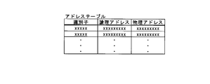
- FIG. 11 is an explanatory diagram showing an example of communication between a plurality of virtual ECUs according to the third embodiment; 10 is a flowchart of a main routine illustrating processing performed by the arithmetic device of the third embodiment; FIG. 10 is a flowchart illustrating a processing procedure of an arithmetic device related to a subroutine of processing of a virtual ECU; FIG. 10 is a flowchart illustrating a processing procedure of a computing device related to a subroutine of processing by a management unit; 4 is a conceptual diagram illustrating contents of an address table; FIG.
- communication may be performed between a plurality of virtual devices via a storage unit such as a memory included in the electronic control device.
- the transmission source virtual device writes the communication data to the storage unit
- the transmission destination virtual device reads the communication data written in the storage unit. Data is exchanged.
- communication data may be read out while the communication data is being written to the storage unit, or a so-called access conflict may occur, which may hinder efficient communication between multiple virtual devices. be.
- the present disclosure has been made in view of such circumstances, and aims to provide an in-vehicle device or the like capable of efficiently exchanging communication data between a plurality of virtual devices.
- An in-vehicle device includes a control unit that executes a plurality of programs, and a storage unit that stores a virtualization operating system activated by the control unit.
- a plurality of virtual devices are generated as an operating environment for the program, and the virtual devices are allocated by dividing the storage unit into areas, and exchanged in communication between the plurality of virtual devices.
- the communication data to the other virtual device is written in the communication buffer of the own virtual device, and the plurality of virtual devices are managed.
- the management unit reads the communication data written in the communication buffer of the virtual device while the virtual device is not operating, and writes the read communication data to a storage area accessible by the management unit. writing the communication data written in the storage area to the communication buffer of the other virtual device during a period in which the other virtual device to which the communication data is transmitted is not operating; , reads the communication data from the virtual device written in the communication buffer of its own virtual device.
- a plurality of virtual devices are generated by the control unit activating the virtualization operating system.
- the virtual device includes, for example, a virtual control unit to which control units are allocated periodically in a time-sharing manner, and a communication buffer.
- a plurality of virtual devices are managed by a management unit.
- the management unit corresponds to a process generated when executing a management program for managing virtual devices generated by the virtualization operating system.
- one virtual device When one of the plurality of virtual devices communicates with another virtual device, one virtual device writes communication data to be transmitted to the other virtual device into a communication buffer of the one virtual device.
- Read communication data During a period in which one virtual device is not operating, for example, during a period in which the virtual control unit of one virtual device is not assigned to the control unit.
- the management unit writes the read communication data to the storage area.
- the management unit stores Write the communication data written in the area to the communication buffer of the other virtual device.
- the other virtual device reads the communication data written to the communication buffer of the other virtual device.
- Communication data transmitted from another virtual device to one virtual device is written to the communication buffer of one virtual device via a storage area.
- One virtual device reads communication data from another virtual device that is written to one virtual device's communication buffer. Transfer of communication data between one virtual device and another virtual device is performed by the management unit via the storage area.
- communication between one virtual device and another virtual device is performed via the storage area. Since communication data is sent and received by the management unit via the storage area, while one virtual device is writing communication data to the communication buffer, another virtual device does not read the communication data. Since the management unit writes and reads communication data while the virtual device is not operating, the writing of communication data to the communication buffer by the virtual device conflicts with the reading of communication data from the communication buffer by the management unit. do not do. Also, writing of communication data to the communication buffer by the management unit and reading of communication data from the communication buffer by the virtual device do not conflict with each other. Therefore, communication data can be exchanged appropriately between a plurality of virtual devices without competing in the writing and reading of communication data. It can be performed.
- control unit includes a plurality of arithmetic devices, one of the plurality of arithmetic devices functions as the management unit, and a plurality of Of the computing devices, the rest of the computing devices function as the virtual devices.
- the control unit includes a plurality of arithmetic units.
- the arithmetic device is the core.
- One of the plurality of arithmetic units functions as a management unit.
- a virtual device is generated in the rest of the plurality of arithmetic units.
- the rest of the computing units function as generated virtual units.
- the management unit In exchange of communication data between a plurality of virtual devices, the management unit by one arithmetic device writes the communication data written in the communication buffer of the source virtual device into the storage area. Further, the management unit reads the communication data written in the storage area from the storage area, and writes the communication data to the communication buffer of the destination virtual device. Communication data can be sent and received between a plurality of virtual devices without contention in the writing and reading of communication data to and from the storage area, because the management unit based on one arithmetic unit writes and reads communication data to and from the storage area. can be done.
- the control unit includes a plurality of arithmetic devices, and each of the arithmetic devices functions as the management unit, functions as the virtual device, and functions as the management unit. Periodically switching between a period of functioning and a period of functioning as the virtual device, one of the plurality of arithmetic devices functions as the management unit, and a period of time when one of the plurality of arithmetic devices functions as the management unit, It does not overlap with the period during which the other arithmetic device functions as the management unit.
- the control unit includes a plurality of arithmetic units.
- Each computing device periodically switches between a period in which it functions as a management unit and a period in which it functions as a virtual device.
- a virtual device is generated in the arithmetic device during a period in which the arithmetic device functions as a virtual device.
- the computing device also functions as a generated virtual device.
- the arithmetic unit functions as the management unit, and as described above, writes and reads communication data to and from the communication buffer and writes and reads communication data to and from the storage area.
- the period in which the arithmetic device functions as the management unit and the period in which the arithmetic device functions as the virtual device are switched between the period in which one arithmetic device functions as the management unit and the period in which the other arithmetic device functions as the management unit. It is set for each arithmetic unit so that it does not overlap. Since the period in which one arithmetic unit functions as a management unit and the period in which another arithmetic unit functions as a management unit do not overlap, there is no contention between writing and reading of communication data to/from a storage area, and a plurality of virtual units can be managed. It is possible to exchange communication data between them.
- the one arithmetic device functions as the management unit that manages the virtual device generated in the one arithmetic device, and the virtual device generated in the one arithmetic device
- the management unit that manages the virtual device to be created is capable of accessing the communication buffer and the storage area of the virtual device generated in one of the computing devices and is generated in another computing device.
- the communication buffer of the virtual device is inaccessible, the virtual device is accessible to the communication buffer of its own virtual device, and the communication buffer and storage area of the other virtual device are inaccessible. It is possible.
- one or more virtual devices are generated in each computing device.
- One arithmetic device among the plurality of arithmetic devices functions as a virtual device generated in the one arithmetic device.
- One arithmetic device also functions as a management unit that manages virtual devices generated in the one arithmetic device.
- the manager can access the communication buffers and storage areas of one or more virtual devices generated in the one computing device.
- the management unit described above cannot access the communication buffers of the virtual devices generated in other computing devices than the one computing device. It is possible to prevent the management unit from erroneously writing and reading communication data to and from a communication buffer of a virtual device generated in another arithmetic device.
- one virtual device can access the communication buffer of the one virtual device, but other virtual devices among the plurality of generated virtual devices communication buffers and storage areas are inaccessible. It is possible to prevent one virtual device from accidentally writing communication data to the communication buffer of another virtual device. Also, it is possible to prevent one virtual device from erroneously reading communication data written in the communication buffer of another virtual device.
- By restricting access to the communication buffer by the virtual device and the management unit as described above it is possible to prevent communication data from being erroneously written to an unintended communication buffer, and to prevent unintended communication data from being erroneously read from the communication buffer. can be prevented. Since the storage area can be accessed only by the management unit, it is possible to prevent the virtual device from erroneously writing and reading communication data in the storage area.
- the communication buffer includes a reception buffer in which the communication data received by the virtual device is written, and the virtual device writes the communication data to the reception buffer.
- the communication data written in the reception buffer is read, and after reading the communication data, the reception buffer update flag is changed from the ON state to the OFF state. change to
- each communication buffer includes a receive buffer into which communication data received by the virtual device is written.
- Each receive buffer is provided with a receive buffer update flag. If the receive buffer update flag is off, the communication data in the receive buffer has not been updated. When the reception buffer update flag is ON, the communication data in the reception buffer has been updated, so new communication data has been written to the reception buffer.
- the virtual device reads new communication data written in the reception buffer when the reception buffer update flag of the reception buffer of the virtual device is in the ON state. After reading the communication data, the virtual device changes the reception buffer update flag from the on state to the off state, so it is possible to prevent the read communication data from being read again.
- the virtual device can appropriately acquire the newly transmitted communication data by reading the communication data written in the reception buffer based on the reception buffer update flag.
- the communication buffer includes a transmission buffer in which the communication data to be transmitted by the virtual device to the other virtual device is written, and the virtual device stores the communication data is written to the transmission buffer, a transmission buffer update flag indicating that the communication data to be written to the transmission buffer is updated is turned on, and the management unit controls that the transmission buffer update flag is in the on state writing the communication data written to the transmission buffer of the virtual device to the storage area, and after writing the communication data to the storage area, changing the transmission buffer update flag from an on state to an off state; Further, a storage area update flag indicating that the communication data to be written in the storage area is updated is turned on, and when the storage area update flag is in the on state, the communication data written in the storage area is written to the receive buffer of the other virtual device, and after the communication data is written to the receive buffer, the receive buffer update flag is turned on, and the storage area update flag is turned off from the on state. do.
- each communication buffer includes a transmission buffer into which communication data to be transmitted by a virtual device to another virtual device is written.
- Each transmission buffer is provided with a transmission buffer update flag. If the transmission buffer update flag is off, the communication data in the transmission buffer has not been updated. When the transmission buffer update flag is ON, the communication data in the transmission buffer has been updated, so new communication data has been written in the transmission buffer. After writing new communication data to the transmission buffer of the virtual device, the virtual device turns on the transmission buffer update flag of the transmission buffer. When the transmission buffer update flag is ON, the management unit reads new communication data written in the transmission buffer and writes the read communication data into the storage area. A storage area update flag is provided in the storage area. If the storage area update flag is off, the communication data in the storage area has not been updated.
- the management unit When the storage area update flag is ON, the communication data in the storage area has been updated, so new communication data has been written in the storage area. After writing the new communication data to the storage area, the management unit changes the transmission buffer update flag from on to off, and then turns on the storage area update flag.
- the storage area update flag When the storage area update flag is ON, the management unit reads new communication data written in the storage area, and writes the read communication data to the reception buffer of the destination virtual device. After writing the communication data to the reception buffer, the management unit turns on the reception buffer update flag of the reception buffer, and further changes the storage area update flag from on to off. As described above, the destination virtual device reads the new data written in the receive buffer of the virtual device based on the receive buffer update flag.
- the management unit Since the communication data written in the transmission buffer is read when the transmission buffer update flag is in the ON state, it is possible to prevent competition between the writing and reading of communication data in the transmission buffer. Since the management unit turns off the storage area update flag after writing the communication data to the reception buffer, the management unit determines communication data not written to the reception buffer among the communication data written to the storage area. be able to. Since the management unit turns on the reception buffer update flag after writing the communication data to the reception buffer, it is possible to prevent conflicts between writing and reading communication data in the reception buffer.
- the communication buffer includes a transmission buffer in which the communication data to be transmitted from the virtual device to the other virtual device is written, and the virtual device stores the communication data to the transmission buffer, updates a transmission buffer count value indicating the number of times the communication data has been written to the transmission buffer, and stores the transmission buffer count value and the communication data in the storage area.
- the communication data written to the transmission buffer of the virtual device is written to the storage area, and after the communication data is written to the storage area, the updating the storage area count value to the same value as the transmission buffer count value, and when the storage area count value is different from the reception buffer count value indicating the number of times the communication data has been written to the reception buffer,
- the communication data written to the storage area is written to the receive buffer of the other virtual device, and after writing the communication data to the receive buffer, the receive buffer count value is set to the same value as the storage area count value. Also, the receive buffer update flag is turned on.
- each communication buffer includes a transmission buffer.
- a transmission buffer is provided with a transmission buffer count value.
- a storage area count value is provided in the storage area.
- a receive buffer is provided with a receive buffer count value.
- Each of the transmission buffer count value, the storage area count value, and the reception buffer count value is provided for each communication data identifier such as a message ID.
- the transmission source virtual device After writing the communication data to the transmission buffer of the virtual device, the transmission source virtual device updates the transmission buffer count value. For example, the above virtual device increments the send buffer count value of the identifier for the above communication data by one. If the transmission buffer count value and the storage area count value are different, the management unit writes the communication data written in the transmission buffer to the storage area.
- the management unit After writing the communication data to the storage area, the management unit updates the storage area count value to the same value as the transmission buffer count value. If the storage area count value and the reception buffer count value are different, the management unit writes the communication data written in the storage area to the reception buffer of the destination virtual device. If the storage area count value and the reception buffer count value are different, it means that the storage area count value and the reception buffer count value corresponding to the same identifier are different. After writing the communication data to the reception buffer, the management unit updates the reception buffer count value to the same value as the storage area count value, and turns on the reception buffer update flag.
- the destination virtual device reads the new data written in the reception buffer of the virtual device based on the reception buffer update flag. Since the communication data written in the transmission buffer is read based on the transmission buffer count value and the storage area count value, it is possible to prevent conflicts between writing and reading communication data in the transmission buffer. Since the management unit updates the storage area count value after writing the communication data to the storage area, it is possible to prevent competition between writing and reading of communication data in the storage area. After writing the communication data to the reception buffer, the management unit updates the reception buffer count value and turns on the reception buffer update flag, thereby preventing competition between writing and reading communication data in the reception buffer. can.
- the communication buffer includes a program execution storage area for executing the program, and the management unit stores the communication data written in the storage area. Write to the program execution storage area of the destination virtual device.
- the communication buffer includes a program execution storage area for executing the program.
- the program execution memory area is a so-called variable area, and is provided for each virtual device.
- a program execution storage area is indicated by a logical address.
- communication data is written to the program execution storage area.
- the management unit writes the communication data written in the storage area to the program execution storage area of the destination virtual device. Since the management unit directly writes the communication data to the program execution storage area, the virtual device does not need to perform processing for writing the communication data to the program execution storage area. Therefore, the processing performed by the virtual device can be reduced.
- An information processing method generates, in an in-vehicle device, a plurality of virtual devices that serve as operating environments for a plurality of programs, and when the virtual device communicates with another virtual device, writing the communication data to the virtual device in the communication buffer in which the communication data contained in the virtual device and exchanged in the communication between the plurality of the virtual devices is written, and during the period when the virtual device is not operating , reading the communication data written in the communication buffer of the virtual device, writing the read communication data in a storage area, and during a period in which the other virtual device to which the communication data is sent is not operating; and writing the communication data written to the storage area to the communication buffer of the other virtual device, and reading the communication data from the virtual device written to the communication buffer of the other virtual device.
- data can be exchanged appropriately between a plurality of virtual devices without conflict, so that efficient communication can be performed between a plurality of virtual devices.
- Data can be exchanged.
- a computer program is a computer program that causes a computer mounted on a vehicle to execute processing, generates a plurality of virtual devices that serve as operating environments for a plurality of programs, and communication data to the other virtual device is included in the virtual device, and the communication data exchanged in the communication between the plurality of virtual devices is written in the communication buffer while the virtual device is not operating, the communication data written in the communication buffer of the virtual device is read, the read communication data is written in a storage area, and the communication data is sent to writing the communication data written in the storage area to the communication buffer of the other virtual device while the other virtual device is not operating;
- the computer is caused to execute a process of reading the communication data from the virtual device.
- the computer can function as an in-vehicle device of one aspect of the present disclosure.
- FIG. 1 is a schematic diagram illustrating the configuration of an in-vehicle system S according to the first embodiment.
- the in-vehicle system S includes a plurality of in-vehicle ECUs 2 mounted on the vehicle C. As shown in FIG.
- An in-vehicle device 3 is connected to an in-vehicle ECU (Electronic Control Unit) 2 .
- ECU Electronic Control Unit
- the plurality of in-vehicle ECUs 2 includes an integrated in-vehicle ECU 2 (integrated ECU) that controls the entire vehicle C, and an individual in-vehicle ECU 2 that is communicably connected to the integrated in-vehicle ECU 2 and directly connected to the in-vehicle device 3.
- the ECU 2 (individual ECU) may be included.
- the integrated in-vehicle ECU 2 may be communicably connected to an external server (not shown) connected to an external network such as the Internet via an external communication device (not shown).
- the in-vehicle ECU 2 corresponds to an in-vehicle device.
- the integrated vehicle ECU 2 and a plurality of individual vehicle ECUs 2 are communicably connected by the vehicle network 4 forming a star-shaped network topology.
- the integrated in-vehicle ECU 2 is provided at the center of a star-shaped network topology.
- the network topology in the in-vehicle system S is not limited to the above examples.
- the in-vehicle system S may have a configuration in which adjacent individual in-vehicle ECUs 2 are connected to form a loop-shaped network topology, enabling two-way communication and achieving redundancy.
- Individual vehicle-mounted ECUs 2 are arranged in each area of vehicle C and connected to a plurality of vehicle-mounted devices 3 .
- the individual vehicle-mounted ECU 2 transmits and receives signals or data to and from the vehicle-mounted device 3 connected thereto.
- separate vehicle-mounted ECU2 communicates with comprehensive vehicle-mounted ECU2.
- the individual in-vehicle ECU 2 is an in-vehicle relay device such as a gateway or ether switch that relays communication between a plurality of in-vehicle devices 3 connected to the individual in-vehicle ECU 2, or communication between the in-vehicle device 3 and another in-vehicle ECU 2.
- the individual vehicle-mounted ECU 2 may also function as a power distribution device that distributes and relays power output from the power storage device and supplies the power to the vehicle-mounted device 3 connected to its own ECU.
- the in-vehicle device 3 includes, for example, an actuator 30 such as a door opening/closing device and a motor device, and various sensors 31 such as a LiDAR (Light Detection and Ranging), a light sensor, a CMOS (Complementary Metal Oxide Semiconductor) camera, and an infrared sensor. .
- the in-vehicle device 3 is not limited to the above example, and may be a switch such as a door SW (switch) and a lamp SW, or may be a lamp.
- the integrated in-vehicle ECU 2 is, for example, a central control unit such as a vehicle computer.
- the integrated vehicle-mounted ECU 2 generates and outputs control signals to individual vehicle-mounted devices 3 based on data from the vehicle-mounted devices 3 relayed via other vehicle-mounted ECUs 2 such as individual vehicle-mounted ECUs 2 .
- the integrated in-vehicle ECU 2 generates a control signal for controlling the actuator 30, which is the target of the request signal, based on information or data such as a request signal output from another in-vehicle ECU 2, and outputs the generated control signal. It outputs to other in-vehicle ECU2.
- the in-vehicle system S is configured by the integrated in-vehicle ECU 2 and the individual in-vehicle ECU 2, but the in-vehicle system S is not limited to the configuration of the integrated in-vehicle ECU 2 and the individual in-vehicle ECU 2.
- the in-vehicle system S may be composed of a plurality of in-vehicle ECUs 2 connected peer-to-peer by a relay device such as a CAN (Controller Area Network) gateway or Ethernet switch.
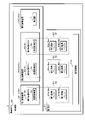
- FIG. 2 is a block diagram illustrating the physical configuration of the in-vehicle ECU 2.
- the in-vehicle ECU 2 includes a control section 20 , a storage section 21 and an in-vehicle communication section 22 .
- the control unit 20 is configured by an arithmetic processing device such as a CPU or MPU (Micro Processing Unit).
- the control unit 20 reads out and executes a control program P and data stored in advance in the storage unit 21, thereby performing various control processing, arithmetic processing, and the like.
- the control unit 20 includes, for example, a single-core single CPU, a single-core multi-CPU, a multi-core single CPU, and a multi-core multi-CPU.
- the control unit 20 is not limited to a software processing unit that performs software processing such as a CPU, but can be used for hardware processing such as FPGA (Field Programmable Gate Array), ASIC (Application Specific Integrated Circuit), or SOC (System on a chip). It may also include a hardware processing unit that performs various control processing, arithmetic processing, and the like.
- FPGA Field Programmable Gate Array
- ASIC Application Specific Integrated Circuit
- SOC System on a chip
- the control unit 20 includes an arithmetic device 200 configured by, for example, one core of a CPU. In this embodiment, an example in which the control unit 20 is a triple-core CPU will be described. Since the control unit 20 is a triple core, it has three cores.
- the control unit 20 includes a first arithmetic unit 201 configured with a first core, a second arithmetic unit 202 configured with a second core, and a third arithmetic unit 203 configured with a third core. It includes three computing units 200 . Note that the number of arithmetic units 200 is not limited to three.
- the storage unit 21 is composed of a volatile memory element such as RAM (Random Access Memory) or a non-volatile memory element such as ROM (Read Only Memory), EEPROM (Electrically Erasable Programmable ROM), or flash memory.
- the storage unit 21 may be configured by a combination of storage devices such as the above volatile memory elements and nonvolatile memory elements.
- the storage unit 21 stores in advance the control program P and data to be referred to during processing.
- the control program P includes, for example, a plurality of programs such as a program for controlling various vehicle-mounted devices 3, or a program for performing target recognition for automated driving based on output data from a LiDAR or CMOS camera. These programs are also called applications.
- storage part 21 of vehicle-mounted ECU2 is memorize
- the control program P stored in the storage unit 21 may be the control program P read from the recording medium A readable by the in-vehicle ECU 2 .
- the control program P may be downloaded from an external computer (not shown) connected to a communication network (not shown) and stored in the storage unit 21 .
- the control program P corresponds to a computer program.
- the in-vehicle communication unit 22 is an input/output interface that uses CAN (Controller Area Network) or Ethernet (registered trademark) communication protocol, for example.
- the control unit 20 communicates with another in-vehicle ECU 2 connected to the in-vehicle network 4 via an in-vehicle communication unit 22 .
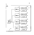
- FIG. 3 is a block diagram illustrating the logical configuration of the in-vehicle ECU 2.
- the storage unit 21 of the in-vehicle ECU 2 stores, for example, a virtualization operating system such as Hypervisor or Xen.
- the control part 20 of vehicle-mounted ECU2 can construct
- a program for controlling various vehicle-mounted devices 3 is executed using one of the plurality of virtual ECUs 5 as an operating environment. That is, these programs are executed on one of the virtual ECUs 5 .
- the virtual ECU 5 executes the program, single or multiple tasks are generated according to the processing contents of the program. A more subdivided or partitioned unit of processing is executed by the task.
- the virtualization method is a hypervisor method in which hardware resources such as the control unit 20 are accessed directly by the virtualization operating system.
- the virtualization method may be a host OS method in which an operating system such as Linux (registered trademark) intervenes between the virtualized operating system and hardware resources.
- the virtualization method may use a container-based virtualization operating system.
- the in-vehicle ECU 2 activated using the virtualized operating system can construct a plurality of virtual ECUs 5 using the functions of the virtualized operating system.
- Hardware resources such as the control part 20 and the memory
- the virtual ECU 5 includes a virtual control unit 5 a assigned to the control unit 20 , a virtual storage unit (not shown) assigned to the storage unit 21 , and a virtual in-vehicle communication unit (not shown) assigned to the in-vehicle communication unit 22 .
- the virtual ECU 5 corresponds to a virtual device.
- the guest OS may be a different kind of OS depending on each virtual ECU 5 . Since the entity of the virtual storage unit is the storage area of the storage unit 21 assigned to each virtual ECU 5 as described above, it goes without saying that the guest OS is also stored in the storage unit 21 in the same manner as the virtualized operating system. .
- a guest OS may be dispensed with, a container may be generated on the virtualized operating system, and a program may be executed on the container. In this case, the container corresponds to the virtual ECU5.
- a plurality of virtual ECUs 5 are generated in the control unit 20 of the in-vehicle ECU 2 activated using the virtualized operating system.
- three virtual ECUs 5 of a first virtual ECU 51, a second virtual ECU 52, and a third virtual ECU 53 are generated.
- the control unit 20 is time-divided and periodically assigned to the virtual control unit 5a of the first virtual ECU 51, the virtual control unit 5a of the second virtual ECU 52, and the virtual control unit 5a of the third virtual ECU 53.
- the first virtual ECU 51 is periodically generated in the first arithmetic unit 201 .
- the virtual control unit 5 a of the generated first virtual ECU 51 is assigned to the first arithmetic unit 201 .
- the first arithmetic device 201 functions as the first virtual ECU 51 .
- the second virtual ECU 52 and the third virtual ECU 53 are generated by alternately switching periodically.
- the virtual control unit 5 a of the generated second virtual ECU 52 is assigned to the second arithmetic unit 202 .
- the virtual control unit 5 a of the generated third virtual ECU 53 is assigned to the second arithmetic unit 202 .
- the second arithmetic device 202 functions as the generated second virtual ECU 52 .
- the second arithmetic unit 202 also functions as the generated third virtual ECU 53 .
- the fact that the virtual ECU 5 is generated in the arithmetic device 200 and the fact that the arithmetic device 200 functions as the virtual ECU 5 generated by the arithmetic device 200 are also referred to as that the arithmetic device 200 generates the virtual ECU 5 .
- the third arithmetic unit 203 executes a virtual ECU management program that manages all virtual ECUs 5 .
- the third arithmetic unit 203 functions as a control panel of the virtualized operating system by executing the virtual ECU management program.
- the 3rd arithmetic unit 203 functions as the management part 1 which manages several virtual ECU5 by running a virtual ECU management program.
- the management unit 1 refers to the allocation time information stored in the storage unit 21, for example, to allocate the utilization time of the first arithmetic unit 201 or the utilization time of the second arithmetic unit 202 to the virtual ECU 5; So-called scheduling is performed.
- the allocation time information includes the cycle in which the first virtual ECU 51 is generated and the time during which the first virtual ECU 51 is allocated.
- the allocation time information includes the cycle of generating the second virtual ECU 52 and the time allocated to the second virtual ECU 52, and the cycle of generating the third virtual ECU 53 and the time allocated to the third virtual ECU 53.
- the time during which the virtual ECU 5 is allocated is also referred to as the allocation time of the virtual ECU 5 .
- the time allocated to the first virtual ECU 51 is also referred to as the allocated time of the first virtual ECU 51 .
- the management unit 1 performs scheduling and starts the operations of the first virtual ECU 51, the second virtual ECU 52, and the third virtual ECU 53, respectively. In other words, the management unit 1 performs switching of the virtual ECU 5 for the first arithmetic device 201 and switching of the virtual ECU 5 for the second arithmetic device 202 by scheduling.
- the virtual ECU 5 is switched between an active state in which the virtual control unit 5a of the virtual ECU 5 is assigned to the arithmetic unit 200 and an active state in which the virtual control unit 5a of the virtual ECU 5 is not assigned to the arithmetic unit 200. Including switching to and from the inactive state.
- transitioning the virtual ECU 5 from the inactive state to the active state is referred to as activation. Transitioning the virtual ECU 5 from the active state to the inactive state is called deactivation.
- the management unit 1 causes the first arithmetic device 201 to periodically generate (activate) the first virtual ECU 51 by switching the virtual ECU 5 for the first arithmetic device 201 .
- the first virtual ECU 51 is generated again in the first arithmetic device 201 .
- the first arithmetic unit 201 is assigned to the virtual control unit 5a of the regenerated first virtual ECU 51 described above. In other words, by switching the virtual ECU 5 with respect to the first arithmetic unit 201, the first virtual ECU 51 is deactivated and activated after being deactivated.
- the management unit 1 causes the second arithmetic device 202 to generate the second virtual ECU 52 and the third virtual ECU 53 alternately and periodically.
- the virtual ECU 5 for the second arithmetic device 202 the virtual ECU 5 generated in the second arithmetic device 202 is switched from one of the second virtual ECU 52 and the third virtual ECU 53 to the other of the second virtual ECU 52 and the third virtual ECU 53. .
- the other of the second virtual ECU 52 and the third virtual ECU 53 is generated in the second arithmetic unit 202 .
- the second arithmetic unit 202 is assigned to the other virtual control unit 5 a of the second virtual ECU 52 and the third virtual ECU 53 .
- one of the second virtual ECU 52 and the third virtual ECU 53 is deactivated by switching the virtual ECU 5 with respect to the second arithmetic unit 202 .
- the other of the second virtual ECU 52 and the third virtual ECU 53 is activated.
- the storage unit 21 is divided into areas and allocated to the communication buffers 6 including the first communication buffer 61, the second communication buffer 62 and the third communication buffer 63.
- Communication buffer 6 is included in virtual ECU 5 .
- the first communication buffer 61 is included in the first virtual ECU 51 .
- the first communication buffer 61 includes a first transmission buffer 61a and a first reception buffer 61b. Communication data to be transmitted to the other virtual ECU 5 when the first virtual ECU 51 communicates with the other virtual ECU 5 is written in the first transmission buffer 61a. Communication data from the other virtual ECU 5 received by the first virtual ECU 51 is written in the first reception buffer 61b.
- the second communication buffer 62 is included in the second virtual ECU 52.
- the second communication buffer 62 includes a second transmission buffer 62a and a second reception buffer 62b. Communication data to be transmitted to the other virtual ECU 5 when the second virtual ECU 52 communicates with the other virtual ECU 5 is written in the second transmission buffer 62a. Communication data from another virtual ECU 5 that is received by the second virtual ECU 52 is written in the second reception buffer 62b.
- the third communication buffer 63 is included in the third virtual ECU 53.
- the third communication buffer 63 includes a third transmission buffer 63a and a third reception buffer 63b. Communication data to be transmitted to the other virtual ECU 5 when the third virtual ECU 53 communicates with the other virtual ECU 5 is written in the third transmission buffer 63a. Communication data from the other virtual ECU 5 received by the third virtual ECU 53 is written in the third reception buffer 63b.
- the first transmission buffer 61a, the second transmission buffer 62a and the third transmission buffer 63a are included in the transmission buffer.
- the first transmission buffer 61a, the second transmission buffer 62a, and the third transmission buffer 63a are also collectively referred to as the transmission buffer 6a.
- the first receive buffer 61b, the second receive buffer 62b and the third receive buffer 63b are included in the receive buffer.
- the first reception buffer 61b, the second reception buffer 62b, and the third reception buffer 63b are also collectively referred to as the reception buffer 6b.
- Information written in the virtual storage unit and the communication buffer 6 of the virtual ECU 5, such as communication data, is stored in the virtual storage unit and the communication buffer of the virtual ECU 5 allocated in the storage unit 21 even when the generation of the virtual ECU 5 is finished. retained.
- the case where the generation of the virtual ECU 5 has ended includes the case where the virtual ECU 5 is in an inactive state.
- a transmission buffer update flag indicating that the communication data written to the transmission buffer 6a has been updated is provided for each communication data identifier such as a message ID.
- the identifier of the communication data is not limited to the message ID, and may be, for example, port number information or an IP address included in the communication data.
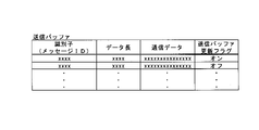
- FIG. 4 is a schematic diagram illustrating the configuration of the transmission buffer 6a.
- the transmission buffer 6a an area for storing communication data, an identifier of the communication data, a data length of the communication data, and a transmission buffer update flag of the communication data in association with each other is provided for each identifier.
- the transmission buffer 6a of FIG. 4 can distinguish and store a plurality of pieces of communication data.
- the virtual ECU 5 When communicating with another virtual ECU 5, the virtual ECU 5 writes communication data to be sent to the other virtual ECU 5 into the transmission buffer 6a included in its own virtual ECU. When writing new communication data to the transmission buffer 6a, the virtual ECU 5 overwrites the communication data associated with the same identifier as the identifier of the new communication data in the transmission buffer 6a with the new communication data. In other words, the communication data of the identifier is updated in the transmission buffer 6a.
- the transmission buffer update flag includes an OFF state and an ON state. If the transmission buffer update flag is off, the communication data in the transmission buffer 6a has not been updated. When the transmission buffer update flag is on, the communication data in the transmission buffer 6a has been updated. Therefore, the communication data for which the transmission buffer update flag is on in the transmission buffer 6a has been newly written to the transmission buffer 6a. communication data.
- the virtual ECU 5 After writing the communication data, the virtual ECU 5 turns on the transmission buffer update flag for the communication data.
- the number of pieces of communication data that the virtual ECU 5 writes into the transmission buffer 6a may be one or plural.
- the virtual ECU 5 turns on the transmission buffer update flag of each piece of communication data.
- the first virtual ECU 51 writes communication data to be transmitted to at least one of the second virtual ECU 52 and the third virtual ECU 53 into the first transmission buffer 61a. After writing the communication data to the first transmission buffer 61a, the first virtual ECU 51 turns on the transmission buffer update flag of the communication data in the first transmission buffer 61a.
- the second virtual ECU 52 writes communication data into the second transmission buffer 62a. After writing the communication data, the second virtual ECU 52 turns on the transmission buffer update flag of the communication data in the second transmission buffer 62a.
- the third virtual ECU 53 writes the communication data into the third transmission buffer 63a. After writing the communication data, the third virtual ECU 53 turns on the transmission buffer update flag of the communication data in the third transmission buffer 63a.
- FIG. 5 is a schematic diagram illustrating the configuration of the receive buffer 6b.
- the reception buffer 6b an area is provided for each identifier in which communication data, an identifier of the communication data, a data length of the communication data, and a reception buffer update flag of the communication data are associated and stored.
- the receiving buffer 6b in FIG. 5 can distinguish and store a plurality of pieces of communication data. Although the details will be described later, the management unit 1 writes communication data into the reception buffer.
- the management unit 1 When writing new communication data to the reception buffer 6b, the management unit 1 overwrites the communication data associated with the same identifier as the identifier of the new communication data in the reception buffer 6b with the new communication data. In other words, the communication data of the above identifier is updated in the reception buffer 6b.
- the receive buffer update flag includes an off state and an on state. If the receive buffer update flag is off, the communication data in the receive buffer 6b has not been updated. When the reception buffer update flag is ON, the communication data in the reception buffer 6b has been updated. Therefore, the communication data for which the reception buffer update flag is ON in the reception buffer 6b has been newly written to the reception buffer 6b. communication data.
- the virtual ECU 5 reads the updated communication data from the reception buffer 6b when the reception buffer update flag in the reception buffer 6b of its own virtual ECU is in the ON state. Specifically, when the receive buffer update flag is on, at least one of the receive buffer update flags associated with the communication data written to the receive buffer 6b is on. In this case, the virtual ECU 5 reads the communication data whose reception buffer update flag is in the ON state in the reception buffer 6b of its own virtual ECU. For example, when the number of pieces of communication data whose reception buffer update flag is on is plural, the virtual ECU 5 reads the plural pieces of communication data. After reading the communication data, the virtual ECU 5 changes the reception buffer update flag of the communication data from ON to OFF. The virtual ECU 5 executes the program using the read communication data.
- the first virtual ECU 51 when the reception buffer update flag of the first reception buffer 61b is ON, the first virtual ECU 51 reads updated communication data from the first reception buffer 61b. After reading the communication data, the first virtual ECU 51 turns off the reception buffer update flag of the first reception buffer 61b.
- the second virtual ECU 52 When the reception buffer update flag of the second reception buffer 62b is ON, the second virtual ECU 52 reads the updated communication data from the second reception buffer 62b. After reading the communication data, the second virtual ECU 52 turns off the reception buffer update flag of the second reception buffer 62b.
- the third virtual ECU 53 reads the updated communication data from the third reception buffer 63b when the reception buffer update flag of the third reception buffer 63b is in the ON state. After reading the communication data, the third virtual ECU 53 turns off the reception buffer update flag of the third reception buffer 63b.
- the storage unit 21 includes a storage area 210 accessible only by the management unit 1 out of the first virtual ECU 51, the second virtual ECU 52, the third virtual ECU 53, and the management unit 1.
- a storage area update flag indicating that the communication data written in the storage area 210 has been updated is provided for each communication data identifier.
- the management unit 1 writes the communication data written in the transmission buffer 6 a to the storage area 210 and temporarily stores the communication data in the storage area 210 .
- the communication data is written in the storage area 210 in association with the identifier of the communication data, the data length of the communication data, and the storage area update flag of the communication data.
- One or a plurality of pieces of communication data are distinguished and written in the storage area 210 .
- the management unit 1 stores in the storage area 210 communication data associated with the same identifier as the identifier of the new communication data. Overwrite the data above the communication data. In other words, in the storage area 210 the communication data of the above identifier are updated.
- the storage area update flag includes an OFF state and an ON state.
- the storage area update flag is off, the communication data in storage area 210 has not been updated.
- the storage area update flag is on, the communication data in storage area 210 has been updated. communication data.
- the management unit 1 When the transmission buffer update flag in the transmission buffer 6a of one of the three virtual ECUs 5 is ON, the management unit 1 reads updated communication data from the transmission buffer 6a. Specifically, when the transmission buffer update flag is on, at least one of the transmission buffer update flags associated with the communication data written to the transmission buffer 6a is on. When the transmission buffer update flag is in the ON state, the management unit 1 reads communication data whose transmission buffer update flag is in the ON state from the transmission buffer 6a of the virtual ECU 5 of one. The management unit 1 writes the read communication data to the storage area 210 .
- the reading of communication data from the transmission buffer 6a of the virtual ECU 5 is performed during the period in which the virtual control unit 5a of the virtual ECU 5 is not assigned to the arithmetic device 200, that is, the control unit 20 is read out. is performed during a period in which the virtual control unit 5a of the virtual ECU 5 is not assigned.
- a period during which the virtual control unit 5 a of the virtual ECU 5 is not assigned to the control unit 20 is also referred to as a period during which the virtual ECU 5 is not assigned to the control unit 20 .
- the period during which the virtual ECU 5 is not assigned to the control unit 20 is the period during which the virtual ECU 5 is inactive.
- a period during which the virtual ECU 5 is not assigned to the control unit 20 corresponds to a period during which the virtual ECU 5 is not operating.
- the management unit 1 After writing the communication data to the storage area 210, the management unit 1 changes the transmission buffer update flag of the communication data in the transmission buffer 6a of the virtual ECU 5 from ON to OFF. Furthermore, the management unit 1 turns on the storage area update flag for the communication data in the storage area 210 .
- the management unit 1 determines whether the transmission buffer update flag of the first transmission buffer 61a is ON during the period in which the virtual control unit 5a of the first virtual ECU 51 is not assigned to the first arithmetic unit 201.
- the management unit 1 reads communication data with the transmission buffer update flag in the ON state from the first transmission buffer 61a.
- the management unit 1 turns off the transmission buffer update flag.
- Management unit 1 writes the read communication data to storage area 210 .
- the management unit 1 turns on the storage area update flag of the written communication data.
- the management unit 1 selects communication data whose storage area update flag is in an ON state and whose transmission destination is the virtual ECU 5 that is to start operation next. is written into the reception buffer 6b of the virtual ECU 5 that starts the operation.
- the communication data written in the transmission buffer 6 a of the virtual ECU 5 of the transmission source is written into the reception buffer 6 b of the virtual ECU 5 of the transmission destination via the storage area 210 .
- the management unit 1 determines the destination virtual ECU 5 based on the information about the destination of the communication data.
- the information about the destination may be included in the communication data, or may be stored in the storage unit 21 in advance.
- the management unit 1 After writing the communication data to the reception buffer 6b, the management unit 1 turns on the reception buffer update flag of the communication data written in the reception buffer 6b. Furthermore, the management unit 1 turns off the storage area update flag for the communication data in the storage area 210 . For example, when a plurality of virtual ECUs 5 are destinations of communication data, the management unit 1 turns off the storage area update flag of the communication data after writing the communication data in all of the reception buffers 6b of the destination virtual ECUs 5. to The destination virtual ECU 5 reads the communication data written in the reception buffer 6b of its own virtual ECU based on the reception buffer update flag as described above.
- the management unit 1 determines whether the storage area update flag is ON before starting the operation of the first virtual ECU 51.
- the storage area update flag is on, at least one of the storage area update flags of the communication data written to the storage area 210 is on.
- the management unit 1 transfers the communication data whose storage area update flag is in the ON state and whose transmission destination is the first virtual ECU 51 to the first reception buffer 61b. Write.
- the management unit 1 turns on the reception buffer update flag of the written communication data in the first reception buffer 61b.
- the management unit 1 also turns off the storage area update flag for the communication data in the storage area 210 .
- the management unit 1 may write the communication data whose storage area update flag is in the ON state to each of the reception buffers 6b of all the virtual ECUs 5 other than the virtual ECU 5 that is the transmission source of the communication data. That is, the management unit 1 may write communication data whose storage area update flag is in the ON state to the reception buffer 6b of the virtual ECU 5 to be operated next without considering the transmission destination of the communication data. In this case, when the communication data is written in the reception buffers 6b of all the virtual ECUs 5 other than the virtual ECU 5 which is the transmission source of the communication data, the management unit 1 turns the storage area update flag from the ON state to the OFF state.
- the virtual ECU 5 acquires the communication data from the reception buffer 6b when the communication data is to be received by the own virtual ECU.
- the virtual ECU 5 discards the communication data when the communication data is not to be received by the own virtual ECU.
- the receiving buffer 6b may be configured such that only messages to be received by the virtual ECU 5 including the receiving buffer 6b are written.
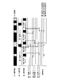
- FIG. 6 is an explanatory diagram showing an example of communication between a plurality of virtual ECUs 5.
- the transmission destinations of communication data are all virtual ECUs 5 other than the transmission source.
- the third arithmetic unit 203 functions as the management unit 1.
- FIG. In FIG. 6, the management unit 1 is indicated as HV (Hypervisor).
- the management unit 1 periodically causes the first arithmetic unit 201 to generate the first virtual ECU 51 and assigns the virtual control unit 5 a of the generated first virtual ECU 51 to the first arithmetic unit 201 .
- a predetermined time is provided between the period during which the first virtual ECU 51 is generated and the period during which the first virtual ECU 51 is generated again.
- the management unit 1 periodically causes the second arithmetic unit 202 to alternately generate the second virtual ECU 52 and the third virtual ECU 53, and performs virtual control of the generated second virtual ECU 52 or the third virtual ECU 53.
- the part 5 a is assigned to the second arithmetic unit 202 .
- a predetermined period of time is provided between the period during which the second virtual ECU 52 is generated and the period during which the third virtual ECU 53 is generated.
- the predetermined time for the first virtual ECU 51 and the predetermined time for the second virtual ECU 52 and the third virtual ECU 53 may be the same or different. In FIG. 6, the period during which the first virtual ECU 51 is generated is longer than the period during which the second virtual ECU 52 is generated and the period during which the third virtual ECU 53 is generated.
- the management unit 1 causes the first arithmetic device 201 to start generating the first virtual ECU 51 and causes the second arithmetic device 202 to start generating the second virtual ECU 52 .
- Starting generation of the virtual ECU 5 includes activation of the virtual ECU 5 .
- the second virtual ECU 52 writes the communication data to the second transmission buffer 62a, and turns on the transmission buffer update flag of the second transmission buffer 62a as described above.
- solid arrows indicate writing or reading of communication data by the virtual ECU 5 .
- a dashed arrow indicates writing or reading of communication data by the management unit 1 .
- the management unit 1 causes the second arithmetic device 202 to finish generating the second virtual ECU 52 and causes the second arithmetic device 202 to start generating the third virtual ECU 53 . In other words, the management unit 1 switches the virtual ECU 5 with respect to the second arithmetic unit 202 .
- the end of generation of the virtual ECU 5 includes deactivation of the virtual ECU 5 .
- the management unit 1 performs the following processing during the period from when the second arithmetic device 202 finishes generating the second virtual ECU 52 to when the second arithmetic device 202 starts generating the third virtual ECU 53 .
- the management unit 1 reads the communication data for which the transmission buffer update flag of the second transmission buffer 62a is in the ON state from the second transmission buffer 62a, and writes the communication data to the storage area 210.
- the management unit 1 changes the transmission buffer update flag of the communication data read from the second transmission buffer 62a from ON to OFF, and changes the storage area update flag of the communication data written to the storage area 210 to the ON state.
- the storage areas 210 shown in FIG. 6 are shown separately for each transmission source of the communication data.
- the management unit 1 Since the virtual ECU 5 that the management unit 1 causes the next operation to start is the third virtual ECU 53, the management unit 1 stores the communication data whose storage area update flag is ON based on the storage area update flag as described above. 210, and writes the communication data into the third reception buffer 63b. In the example of FIG. 6, communication data transmitted from the second virtual ECU 52 is written in the third reception buffer 63b. As described above, the management unit 1 turns on the reception buffer update flag of the communication data written in the third reception buffer 63b. During the period from when the second arithmetic unit 202 finishes generating the second virtual ECU 52 to when the second arithmetic unit 202 starts generating the third virtual ECU 53, the virtual control unit 20 controls the virtual ECU 5. It is included in the period during which the portion 5a is not assigned.
- the third virtual ECU 53 generated in the second arithmetic unit 202 transmits the communication data for which the reception buffer update flag of the third reception buffer 63b is in the ON state from the third reception buffer 63b. read out.
- the third virtual ECU 53 reads communication data transmitted from the second virtual ECU 52 .
- Communication data is exchanged between the third virtual ECU 53 and the second virtual ECU 52 via the storage area 210 . That is, communication between the third virtual ECU 53 and the second virtual ECU 52 is performed.
- the third virtual ECU 53 changes the reception buffer update flag of the read communication data from ON to OFF.
- the first virtual ECU 51 writes the communication data to the first transmission buffer 61a and turns on the transmission buffer update flag of the first transmission buffer 61a as described above.
- the management unit 1 causes the first arithmetic device 201 to finish generating the first virtual ECU 51 and causes the first arithmetic device 201 to start generating the first virtual ECU 51 again. In other words, the management unit 1 switches the virtual ECU 5 with respect to the second arithmetic device 202 .
- the management unit 1 performs the following processing. . As described above, based on the transmission buffer update flag, the management unit 1 reads communication data for which the transmission buffer update flag of the first transmission buffer 61a is in the ON state from the first transmission buffer 61a, and writes the communication data to the storage area 210. . As described above, the management unit 1 changes the transmission buffer update flag of the communication data read in the first transmission buffer from ON to OFF, and turns the storage area update flag of the communication data written to the storage area 210 to ON. do.
- the management unit 1 Since the first virtual ECU 51 is the first virtual ECU 51 that the management unit 1 causes the next operation to start, the management unit 1 stores the communication data whose storage area update flag is ON based on the storage area update flag as described above. It reads from the area 210 and writes the communication data into the first reception buffer 61b. In the example of FIG. 6, communication data transmitted from the second virtual ECU 52 is written in the first reception buffer 61b. The management unit 1 turns on the reception buffer update flag of the communication data written in the first reception buffer 61b. The destination of each communication data in the example of FIG. 6 is all the virtual ECUs 5 other than the source.
- the management unit 1 Since the communication data whose transmission source is the second virtual ECU 52 has been written to the first reception buffer 61b and the third reception buffer 63b, the management unit 1 stores the communication data whose transmission source is the second virtual ECU 52 in the storage area 210. storage area update flag is turned off. During the period from when the first arithmetic unit 201 finishes generating the first virtual ECU 51 to when the first arithmetic unit 201 starts generating the first virtual ECU 51 again, the virtual ECU 5 It is included in the period to which the virtual control unit 5a is not assigned.
- the first virtual ECU 51 generated in the first arithmetic unit 201 updates the communication data whose reception buffer update flag of the first reception buffer 61b is in the ON state to the first reception buffer. 61b to obtain the communication data.
- the first virtual ECU 51 changes the reception buffer update flag of the communication data read in the first reception buffer 61b from ON to OFF.
- the third The virtual ECU 53 writes the communication data to the third transmission buffer 63a and turns on the transmission buffer update flag of the communication data written in the third transmission buffer 63a.
- the management unit 1 causes the second arithmetic device 202 to finish generating the third virtual ECU 53 and causes the second arithmetic device 202 to start generating the second virtual ECU 52 . In other words, the management unit 1 switches the virtual ECU 5 with respect to the second arithmetic device 202 . During the period from when the second arithmetic device 202 finishes generating the third virtual ECU 53 to when the second arithmetic device 202 starts generating the second virtual ECU 52, the management unit 1 performs the following processing.
- the management unit 1 reads the communication data whose transmission buffer update flag of the third transmission buffer 63a is in the ON state from the third transmission buffer 63a, and writes the communication data to the storage area 210. . As described above, the management unit 1 changes the transmission buffer update flag of the read communication data from ON to OFF, and turns the storage area update flag of the written communication data to ON.
- the management unit 1 Since the second virtual ECU 52 is the second virtual ECU 52 that the management unit 1 causes the next operation to start, the management unit 1 stores the communication data whose storage area update flag is ON based on the storage area update flag as described above. 210 and writes the communication data into the second receive buffer 62b. In the example of FIG. 6, the communication data whose transmission source is the first virtual ECU 51 and the communication data whose transmission source is the third virtual ECU 53 are written in the second reception buffer 62b. During the period from when the second arithmetic unit 202 finishes generating the third virtual ECU 53 to when the second arithmetic unit 202 starts generating the second virtual ECU 52, the virtual control unit 20 controls the virtual ECU 5. It is included in the period during which the portion 5a is not assigned.
- the second virtual ECU 52 generated in the second arithmetic unit 202 transmits the communication data whose reception buffer update flag of the second reception buffer 62b is in the ON state from the second reception buffer 62b. read out.
- the second virtual ECU 52 reads two pieces of communication data and turns off the reception buffer update flags of the two pieces of communication data read in the second reception buffer 62b.
- the second virtual ECU 52 writes new communication data to the second transmission buffer 62a, and turns on the transmission buffer update flag of the second transmission buffer 62a as described above.
- the management unit 1 switches the virtual ECU 5 with respect to the second arithmetic unit 202 .
- the management unit 1 performs the following processes during the period from the end of generation of the second virtual ECU 52 to the start of generation of the third virtual ECU 53 .
- the management unit 1 writes communication data in which the transmission buffer update flag of the second transmission buffer 62a is in the ON state to the storage area 210.
- FIG. The management unit 1 changes the transmission buffer update flag from on to off, and turns on the storage area update flag of the written communication data.
- the management unit 1 reads communication data whose storage area update flag is in the ON state from the storage area 210, and writes the communication data into the third reception buffer 63b.
- the communication data whose transmission source is the first virtual ECU 51 and the communication data whose transmission source is the second virtual ECU 52 are written in the third reception buffer 63b. Since the communication data whose transmission source is the first virtual ECU 51 has been written to the second reception buffer 62b and the third reception buffer 63b, the management unit 1 stores the communication data whose transmission source is the first virtual ECU 51 in the storage area 210. storage area update flag is turned off.
- the generated third virtual ECU 53 reads the communication data for which the reception buffer update flag of the third reception buffer 63b is ON from the third transmission buffer 63a.
- the third virtual ECU 53 turns off the reception buffer update flag of the communication data read in the third reception buffer 63b.
- communication data is read or written based on update flags including the transmission buffer update flag, storage area update flag, and reception buffer update flag. Also, the update flag is set according to reading or writing of communication data.
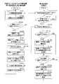
- FIG. 7 is a flowchart illustrating processing performed by the third computing device 203 functioning as the management unit 1 and processing related to generation of the virtual ECU 5 performed by the computing device 200 assigned to the virtual ECU 5 .
- the arithmetic devices 200 assigned to the virtual ECU 5 in this embodiment are the first arithmetic device 201 and the second arithmetic device 202 .
- the third arithmetic unit 203 performs the following processing as the management unit 1 when an IG (ignition) switch (not shown) of the vehicle C changes from an off state to an on state.
- the arithmetic device 200 assigned to the virtual ECU 5 performs the following processing when the IG switch transitions from the OFF state to the ON state.
- the step is abbreviated as S.
- the arithmetic device 200 assigned to the virtual ECU 5 acquires a generation start signal indicating the start of generation of the virtual ECU 5 from the third arithmetic device 203 (S101), and starts generating the virtual ECU 5 (S102).
- the first arithmetic unit 201 among the arithmetic units 200 described above generates the first virtual ECU 51 .
- the second arithmetic unit 202 generates one of the second virtual ECU 52 and the third virtual ECU 53 .
- the arithmetic device 200 assigned to the virtual ECU 5 determines whether or not the reception buffer update flag of the reception buffer 6b of the generated virtual ECU 5 is ON (S103). If the reception buffer update flag is not ON (S103: NO), that is, if the reception buffer update flag is OFF, the computing device 200 assigned to the virtual ECU 5 performs the processing of S106, which will be described later. If the reception buffer update flag is not on, all of the reception buffer update flags associated with the generated communication data written in the reception buffer 6b of the virtual ECU 5 are off.
- the arithmetic unit 200 assigned to the virtual ECU 5 reads the communication data with the reception buffer update flag ON from the reception buffer 6b ( S104).
- the reception buffer update flag is on, at least one of the reception buffer update flags associated with the generated communication data written in the reception buffer 6b of the virtual ECU 5 is on.
- the arithmetic unit 200 assigned to the virtual ECU 5 turns off the reception buffer update flag of the read communication data (S105).
- the arithmetic device 200 assigned to the virtual ECU 5 executes the program (S106).
- the said program is run on virtual ECU5.
- the arithmetic unit 200 assigned to the virtual ECU 5 executes a program using the read communication data when reading the communication data from the reception buffer 6b in the process of S104.
- the arithmetic device 200 assigned to the virtual ECU 5 writes the communication data to the transmission buffer 6a of the generated virtual ECU 5 (S107). As described above, after writing the communication data to the transmission buffer 6a, the arithmetic unit 200 turns on the transmission buffer update flag of the written communication data (S108). The arithmetic device 200 assigned to the virtual ECU 5 acquires the generation end signal indicating the end of generation of the virtual ECU 5 from the third arithmetic device 203 (S109), and ends the generation of the virtual ECU 5 (S110). The arithmetic device 200 assigned to the virtual ECU 5 performs the process of S101. The generated virtual ECU 5 is switched.
- the first arithmetic unit 201 among the arithmetic units 200 described above finishes generating the first virtual ECU 51 and starts generating the first virtual ECU 51 again.
- the second arithmetic unit 202 finishes generating one of the second virtual ECU 52 and the third virtual ECU 53 and starts generating the other of the second virtual ECU 52 and the third virtual ECU 53 .
- the arithmetic unit 200 assigned to the virtual ECU 5 ends the processing when, for example, the IG switch transitions from the ON state to the OFF state.
- the third arithmetic unit 203 outputs a generation start signal to the arithmetic unit 200 assigned to the virtual ECU 5 based on the above-mentioned allocation time information (S111).
- the third arithmetic device 203 causes the first arithmetic device 201 to start generating the first virtual ECU 51 .
- the third arithmetic device 203 causes the second arithmetic device 202 to start generating one of the second virtual ECU 52 and the third virtual ECU 53 .
- the third arithmetic device 203 determines whether or not the time allocated to the virtual ECU 5 has elapsed since the arithmetic device 200 assigned to the virtual ECU 5 started generating the virtual ECU 5 (S112). For example, when the third arithmetic device 203 causes the first arithmetic device 201 to start generating the first virtual ECU 51, the third arithmetic device 203 determines whether the allocation time of the first virtual ECU 51 has elapsed since the time the generation of the first virtual ECU 51 was started. determine whether or not
- the third arithmetic device 203 performs loop processing to perform the processing of S112 again.
- the third arithmetic unit 203 outputs a generation end signal to the arithmetic unit 200 allocated to the virtual ECU 5 based on the allocation time information (S113). It causes the device 201 or the second arithmetic device 202 to finish generating the virtual ECU 5 .
- the third arithmetic unit 203 may perform a standby process from the time when the arithmetic unit 200 assigned to the virtual ECU 5 starts generating the virtual ECU 5 until the allocation time of the virtual ECU 5 elapses. . After the standby process, the third arithmetic unit 203 performs the process of S113.
- the third arithmetic unit 203 determines whether or not the transmission buffer update flag is ON in the transmission buffer 6a of the virtual ECU 5 whose generation has ended (S114). If the transmission buffer update flag is not ON (S114: NO), the process of S117, which will be described later, is performed. If the transmission buffer update flag is not on, all of the reception buffer update flags associated with the communication data written in the reception buffer 6b of the virtual ECU 5 are off.
- the third arithmetic unit 203 reads out the communication data whose transmission buffer update flag is in the ON state from the transmission buffer 6a as described above, and stores the communication data is written in the storage area 210 (S115).
- the transmission buffer update flag is on, at least one of the transmission buffer update flags associated with the communication data written to the transmission buffer 6a is on.
- the third arithmetic unit 203 changes the transmission buffer update flag of the communication data read from the transmission buffer 6a from ON to OFF, and writes the data in the storage area 210. It turns on the storage area update flag of the communication data. That is, the third arithmetic unit 203 updates the transmission buffer update flag and the storage area update flag (S116).
- the third arithmetic unit 203 determines whether or not the storage area update flag is on (S117). If the storage area update flag is ON (S117: YES), the third arithmetic unit 203 performs the following processing. As described above, the third arithmetic unit 203 receives, among the communication data written in the storage area 210, communication data in which the storage area update flag is in an ON state, and the virtual ECU 5 to start operation next is the transmission destination. Certain communication data is read from storage area 210 . The third arithmetic unit 203 writes the communication data read out from the storage area 210 to the reception buffer 6b of the virtual ECU 5 which is to be operated next (S118).
- the third arithmetic unit 203 may write communication data whose storage area update flag is in the ON state to the reception buffer 6b of the virtual ECU 5 to be operated next without considering the transmission destination of the communication data. .
- the third arithmetic unit 203 changes the storage area update flag of the read communication data in the storage area 210 from on to off. Furthermore, the third arithmetic unit 203 turns on the reception buffer update flag of the communication data written in the reception buffer 6b. That is, the third arithmetic unit 203 updates the storage area update flag and the reception buffer update flag (S119). For example, when the number of transmission destinations of the communication data is plural, the third arithmetic unit 203 sets the storage area update flag of the communication data when writing the communication data to the reception buffers 6b of the virtual ECUs 5 of all the transmission destinations. Change from ON state to OFF state.
- the third arithmetic unit 203 performs the process of S111 and switches the virtual ECU 5 to the first arithmetic unit 201 or the second arithmetic unit 202. Specifically, the third arithmetic device 203 causes the first arithmetic device 201 to start generating the first virtual ECU 51 again. Alternatively, the third arithmetic device 203 causes the second arithmetic device 202 to start generating the other of the second virtual ECU 52 and the third virtual ECU 53 . The third arithmetic unit 203 terminates the process when, for example, the IG switch transitions from the ON state to the OFF state.
- the third arithmetic unit 203 performs the processing of S111 and switches the virtual ECU 5 to the first arithmetic unit 201 or the second arithmetic unit 202. If the storage area update flag is not on, all of the storage area update flags associated with the communication data written to the storage area 210 are off.
- a plurality of virtual ECUs 5 are generated in the in-vehicle ECU 2 .
- the third arithmetic device 203 functions as the management unit 1 .
- a virtual control unit 5 a of the virtual ECU 5 is assigned to each of the first arithmetic device 201 and the second arithmetic device 202 .
- Each of the 1st arithmetic unit 201 and the 2nd arithmetic unit 202 functions as virtual ECU5.
- the virtual ECU 5 writes and reads communication data to and from the communication buffer 6 of its own virtual ECU.
- the management unit 1 reads the communication data written in the transmission buffer 6 a and writes the communication data in the storage area 210 .
- the management unit 1 also writes the communication data written in the storage area 210 to the reception buffer 6b of the virtual ECU 5 of the transmission destination.
- Communication data is transferred between the plurality of virtual ECUs 5 via the storage area 210 . That is, the plurality of virtual ECUs 5 communicate via the storage area 210 . Since the storage area 210 is accessible only by the management unit 1 , it is possible to prevent the virtual ECU 5 from erroneously writing and reading communication data in the storage area 210 .
- the management unit 1 Since communication data is exchanged by the management unit 1 via the storage area 210, while one virtual ECU 5 is writing communication data, another virtual ECU 5 does not read the communication data. As described above, the management unit 1 writes and reads communication data during a period in which the virtual control unit 5a is not assigned to the first arithmetic unit 201 or the second arithmetic unit 202. The writing of communication data and the reading of communication data from the communication buffer 6 by the management unit 1 do not conflict. Also, writing of communication data to the communication buffer 6 by the management unit 1 and reading of communication data from the communication buffer 6 by the virtual ECU 5 do not conflict with each other. Specifically, it is possible to prevent conflicts between writing and reading communication data in the transmission buffer 6a.
- the communication data can be appropriately exchanged without competition between writing and reading of the communication data.
- Communication data can be efficiently exchanged between a plurality of virtual ECUs 5 . That is, it is possible to efficiently perform communication between the plurality of virtual ECUs 5 without conflict of access.
- the third arithmetic unit 203 functions as the management unit 1 as described above. That is, one computing device 200 functions as the management unit 1 . Since the management unit 1 based on one arithmetic unit 200 writes and reads communication data to and from the storage area 210, the writing and reading of communication data to and from the storage area 210 do not compete, and communication data between the plurality of virtual ECUs 5 can be transferred. Can give and receive.
- the virtual ECU 5 When the reception buffer update flag of the reception buffer 6b of the virtual ECU 5 is ON, the virtual ECU 5 reads communication data from the reception buffer 6b. Since the virtual ECU 5 changes the reception buffer update flag from the on state to the off state after reading the communication data, it is possible to prevent the already read communication data from being read again. The virtual ECU 5 can appropriately read the newly transmitted communication data by reading the communication data from the reception buffer 6b based on the reception buffer update flag.
- the virtual ECU 5 After writing the communication data to the transmission buffer 6a, the virtual ECU 5 turns on the transmission buffer update flag.
- the transmission buffer update flag When the transmission buffer update flag is ON, the management unit 1 writes the communication data written in the transmission buffer 6a to the storage area 210, and turns off the transmission buffer update flag after writing the communication data to the transmission buffer 6a. state. Since the communication data written in the transmission buffer 6a is read based on the transmission buffer update flag, the management unit 1 can appropriately read newly transmitted communication data from the transmission buffer 6a.
- the management unit 1 turns on the storage area update flag after writing the communication data to the transmission buffer 6a.
- the management unit 1 reads the communication data from the storage area 210 and writes the read communication data into the reception buffer 6b of the virtual ECU 5 as the transmission destination.
- the management unit 1 turns on the reception buffer update flag and changes the storage area update flag from on to off.
- Communication data is read from the storage area 210 and written to the reception buffer 6b based on the storage area update flag. Communication data not written in 6b can be discriminated. Since the management unit 1 turns on the reception buffer update flag after writing the communication data to the reception buffer 6b, the virtual ECU 5 can appropriately read the newly transmitted communication data from the reception buffer 6b.
- Embodiment 2 relates to an in-vehicle ECU 2 that writes communication data to the storage area 210 or the reception buffer 6b based on a count value indicating the number of times the communication data has been updated.
- the in-vehicle ECU 2 of the second embodiment includes a control unit 20 including a first arithmetic device 201, a second arithmetic device 202 and a third arithmetic device 203, as in the first embodiment.
- the first arithmetic device 201 periodically generates the first virtual ECU 51 .
- the second arithmetic unit 202 periodically and alternately generates the second virtual ECU 52 and the third virtual ECU 53 .
- the third arithmetic unit 203 functions as the management unit 1 .
- Each of the transmission buffers 6a of the plurality of virtual ECUs 5 including the first virtual ECU 51, the second virtual ECU 52, and the third virtual ECU 53 has a transmission buffer count value indicating the number of times communication data is written in the transmission buffer 6a. provided for each.
- the transmission buffer count value is associated with communication data for each communication data identifier in the transmission buffer 6a in the same manner as the transmission buffer update flag of the first embodiment.
- the virtual ECU 5 After writing the communication data to the transmission buffer 6a of the virtual ECU 5, the virtual ECU 5 increases the transmission buffer count value of the written communication data by one in the transmission buffer 6a. That is, the virtual ECU 5 updates the transmission buffer count value.
- the virtual ECU 5 updates the transmission buffer count value to an initial value, such as 0, when updating the transmission buffer count value when the transmission buffer count value is the maximum value.
- the virtual ECU 5 overwrites the already written communication data having the same identifier with the communication data to be written when writing the communication data to the transmission buffer 6a.
- a storage area count value indicating the number of times communication data is written in the storage area 210 is provided for each communication data identifier.
- the storage area count value is associated with the communication data for each communication data identifier in the storage area 210 in the same manner as the storage area update flag of the first embodiment.
- the management unit 1 increments the storage area count value of the written communication data in the storage area 210 by one. That is, the management unit 1 updates the storage area count value. For example, when updating the storage area count value when the storage area count value is the maximum value, the management unit 1 updates the storage area count value to an initial value, such as 0.
- Writing of communication data to the storage area 210 is performed by the management unit 1 during a period in which the virtual control unit 5a of the virtual ECU 5 is not assigned to the control unit 20, as in the first embodiment.
- the management unit 1 compares the transmission buffer count value and the storage area count value, and writes the communication data in the transmission buffer 6a to the storage area 210 when the transmission buffer count value and the storage area count value are different.
- the transmission buffer count value of one communication data in the transmission buffer 6a and the storage area count value of the one communication data in the storage area 210 are different. is the case.
- one piece of communication data in the transmission buffer 6a is communication data newly transmitted from the virtual ECU 5 .
- the management unit 1 reads the communication data of the transmission buffer count value different from the storage area count value from the transmission buffer 6a, and stores the communication data in the storage area 210. write to
- the management unit 1 After writing the communication data to the storage area 210, the management unit 1 updates the storage area count value of the communication data to the same value as the transmission buffer count value. Specifically, the management unit 1 sets the storage area count value of the communication data written in the storage area 210 to the transmission buffer count value associated with the communication data having the same identifier as the above communication data identifier in the transmission buffer 6a. Update to the same value.
- Each of the reception buffers 6b of the plurality of virtual ECUs 5 is provided with a reception buffer update flag for each communication data identifier, as in the first embodiment.
- a reception buffer count value indicating the number of times communication data is written in the reception buffer 6b is provided for each communication data identifier. Similar to the reception buffer update flag, the reception buffer count value is associated with communication data for each communication data identifier in the reception buffer 6b.
- the management unit 1 After writing the communication data to the reception buffer 6b of the destination virtual ECU 5, the management unit 1 increases the reception buffer count value of the written communication data by one in the reception buffer 6b. That is, the management unit 1 updates the reception buffer count value. For example, when updating the reception buffer count value when the reception buffer count value is the maximum value, the management unit 1 updates the reception buffer count value to an initial value, for example, 0.
- the management unit 1 when writing communication data to the storage area 210 and writing communication data to the reception buffer 6b, the management unit 1 writes the communication data to be written with the same identifier that has already been written. Overwrite communication data.
- Writing of communication data to the reception buffer 6b is performed by the management unit 1 during a period in which the virtual control unit 5a of the virtual ECU 5 is not assigned to the control unit 20, as in the first embodiment.
- the management unit 1 compares the storage area count value with the reception buffer count value of the reception buffer 6b of the virtual ECU 5 to be operated next, and stores when the storage area count value and the reception buffer count value are different.
- the communication data in the area 210 is written into the reception buffer 6b. Specifically, when the storage area count value and the reception buffer count value are different, the storage area count value of one communication data in the storage area 210 and the reception buffer count value of the communication data in the reception buffer 6b are are different.
- one piece of communication data in storage area 210 is newly transmitted communication data.
- the management unit 1 reads out the communication data of the storage area count value different from the reception buffer count value from the storage area 210, and stores the communication data in the reception buffer 6b. write to
- the management unit 1 After writing the communication data to the reception buffer 6b, the management unit 1 turns on the reception buffer update flag as in the first embodiment. Furthermore, after writing the communication data to the reception buffer 6b, the management unit 1 updates the reception buffer count value of the communication data to the same value as the transmission buffer count value. Specifically, the management unit 1 makes the reception buffer count value of the communication data written to the reception buffer 6b equal to the storage area count value associated with the communication data having the same identifier as the identifier of the communication data in the storage area 210. to the value of
- the virtual ECU 5 reads communication data whose reception buffer update flag is in the ON state from the reception buffer 6b of its own virtual ECU in the same manner as in the first embodiment.
- the virtual ECU 5 changes the reception buffer update flag from ON to OFF after reading the communication data.
- communication data is written to the reception buffer 6b of each virtual ECU 5 based on the storage area count value and the reception buffer count value of each virtual ECU 5 as described above.
- the communication data whose storage area update flag is in the ON state is written to the reception buffer 6b of all virtual ECUs 5 as transmission destinations.
- the storage area update flag is changed to the off state.
- the data already written to the reception buffer 6b may be written again to the reception buffer 6b. That is, the virtual ECU 5 may read the same communication data as the already read communication data.
- the management unit 1 can prevent the virtual ECU 5 from reading the same communication data as the communication data already read. can.
- FIG. 8 is a flowchart illustrating processing performed by the third arithmetic device 203 functioning as the management unit 1 of the second embodiment and processing related to generation of the virtual ECU 5 performed by the arithmetic device 200 assigned to the virtual ECU 5 of the second embodiment.
- the arithmetic devices 200 assigned to the virtual ECU 5 in this embodiment are the first arithmetic device 201 and the second arithmetic device 202 .
- the third arithmetic unit 203 performs the following processing as the management unit 1 when the IG switch (not shown) of the vehicle C transitions from the off state to the on state.
- the arithmetic device 200 assigned to the virtual ECU 5 performs the following processing when the IG switch transitions from the OFF state to the ON state.
- the computing device 200 assigned to the virtual ECU 5 performs the processes of S201 and S202. Since the processes of S201 and S202 are the same as the processes of S101 and S102 of the first embodiment, detailed description thereof will be omitted.
- Generation of the first virtual ECU 51 is started in the first arithmetic unit 201 . Also, the generation of one of the second virtual ECU 52 and the third virtual ECU 53 is started in the second arithmetic unit 202 .
- the computing device 200 assigned to the virtual ECU 5 performs the processing of S203. Since the processing of S203 is the same as the processing of S103 of the first embodiment, detailed description is omitted. If the reception buffer update flag is not ON (S203: NO), the arithmetic unit 200 assigned to the virtual ECU 5 performs the process of S206, which will be described later.
- the arithmetic device 200 assigned to the virtual ECU 5 When the reception buffer update flag is ON (S203: YES), the arithmetic device 200 assigned to the virtual ECU 5 performs the processes of S204, S205, S206 and S207. Since the processes of S204, S205, S206 and S207 are the same as the processes of S104, S105, S106 and S107 of the first embodiment, detailed description thereof will be omitted.
- the arithmetic device 200 assigned to the virtual ECU 5 updates the transmission buffer count value as described above (S208).
- the computing device 200 assigned to the virtual ECU 5 performs the processes of S209 and S210. Since the processes of S209 and S210 are the same as the processes of S109 and S110 of the first embodiment, detailed description thereof will be omitted. Furthermore, the arithmetic unit 200 assigned to the virtual ECU 5 performs the process of S201. The generated virtual ECU 5 is switched. Specifically, the first arithmetic unit 201 starts generating the first virtual ECU 51 again. The second arithmetic unit 202 also starts generating the other of the second virtual ECU 52 and the third virtual ECU 53 . The arithmetic unit 200 assigned to the virtual ECU 5 ends the process when, for example, the IG switch transitions from the ON state to the OFF state.
- the third arithmetic unit 203 performs the processes of S211 and S212. Since the processes of S211 and S212 are the same as the processes of S111 and S112 of the first embodiment, detailed description thereof will be omitted. If the allocated time of the virtual ECU 5 has not elapsed (S212: NO), the third arithmetic device 203 performs loop processing to perform the processing of S212 again. When the allocated time of the virtual ECU 5 has passed (S212: YES), the third arithmetic device 203 performs the process of S213. Since the processing of S213 is the same as the processing of S113 of the first embodiment, detailed description is omitted.
- the third arithmetic unit 203 may perform a standby process from the time when the arithmetic unit 200 assigned to the virtual ECU 5 starts generating the virtual ECU 5 until the allocation time of the virtual ECU 5 elapses. . After the standby process, the third arithmetic unit 203 performs the process of S213.
- the third arithmetic unit 203 determines whether the transmission buffer count value and the storage area count value are different (S214). If the transmission buffer count value and the storage area count value do not differ (S214: NO), that is, if the transmission buffer count value and the storage area count value are the same value, the third arithmetic unit 203 process.
- the third arithmetic unit 203 reads the communication data of the transmission buffer count value different from the storage area count value from the transmission buffer 6a as described above, The communication data is written in the storage area 210 (S215). As described above, after writing the communication data to the storage area 210, the third arithmetic unit 203 updates the storage area count value of the communication data to the same value as the transmission buffer count value (S216).
- the third arithmetic unit 203 determines whether or not the reception buffer count value of the reception buffer 6b of the virtual ECU 5 to be operated next differs from the storage area count value (S217). If the receive buffer count value and the storage area count value are different (S217: YES), the third arithmetic unit 203 reads the communication data of the storage area count value different from the receive buffer count value from the storage area 210 as described above, The communication data is written in the reception buffer 6b (S218).
- the third arithmetic unit 203 updates the reception buffer count value of the communication data (S219). Furthermore, the third arithmetic unit 203 turns on the reception buffer update flag of the written communication data (S220).
- the third arithmetic device 203 performs the process of S211 and switches the virtual ECU 5 with respect to the first arithmetic device 201 or the second arithmetic device 202 . Specifically, the third arithmetic device 203 causes the first arithmetic device 201 to start generating the first virtual ECU 51 again.
- the third arithmetic device 203 causes the second arithmetic device 202 to start generating the other of the second virtual ECU 52 and the third virtual ECU 53 .
- the third arithmetic unit 203 terminates the process when, for example, the IG switch transitions from the ON state to the OFF state.
- the third arithmetic unit 203 performs the process of S211. conduct. That is, the third arithmetic device 203 switches the virtual ECU 5 with respect to the first arithmetic device 201 or the second arithmetic device 202 .
- the communication data written in the transmission buffer 6a is read based on the transmission buffer count value and the storage area count value. can be prevented.
- the management unit 1 updates the storage area count value after writing the communication data to the storage area 210 . Since the management unit 1 reads communication data from the storage area 210 based on the reception buffer count value and the storage area count value, it is possible to prevent communication data that has not been updated in the storage area 210 from being read.
- the management unit 1 After writing the communication data to the reception buffer 6b, the management unit 1 updates the reception buffer count value and turns on the reception buffer update flag. can be prevented.
- the in-vehicle ECU 2 may determine that an abnormality has occurred in communication between the virtual ECUs 5 .
- FIG. 9 is a block diagram illustrating the logical configuration of the in-vehicle ECU 2 of the third embodiment.
- the same components as in the first embodiment are denoted by the same reference numerals, and detailed description thereof will be omitted.
- Embodiment 3 relates to an in-vehicle ECU 2 that periodically switches between a period in which the arithmetic unit 200 of the control unit 20 functions as the management unit 1 and a period in which the virtual ECU 5 functions.
- the in-vehicle ECU 2 of Embodiment 3 includes a control unit 20 including two arithmetic units 200 , a first arithmetic unit 201 and a second arithmetic unit 202 .
- the first virtual ECU 51 is generated in the first arithmetic device 201 .
- the virtual control unit 5 a of the generated first virtual ECU 51 is assigned to the first arithmetic unit 201 .
- the first arithmetic device 201 functions as a management unit 1 that manages the virtual ECU 5 generated by the first arithmetic device 201 .
- the first arithmetic unit 201 functions as a management unit 1 that manages the first virtual ECU 51 .
- the management unit 1 that manages the virtual ECU 5 generated by the first arithmetic unit 201 is also referred to as a first management unit 11 .
- the first management unit 11 switches the virtual ECU 5 for the first arithmetic device 201 and causes the first arithmetic device 201 to periodically generate the first virtual ECU 51 .
- the second virtual ECU 52 and the third virtual ECU 53 are alternately generated periodically in the second arithmetic unit 202 .
- the virtual control unit 5 a of the generated second virtual ECU 52 is assigned to the second arithmetic device 202 .
- the virtual control unit 5 a of the generated third virtual ECU 53 is assigned to the second arithmetic unit 202 .
- the second arithmetic device 202 functions as a management unit 1 that manages the virtual ECU 5 generated by the second arithmetic device 202 . That is, the second arithmetic unit 202 functions as a management unit 1 that manages the second virtual ECU 52 and the third virtual ECU 53 .
- the management unit 1 that manages the virtual ECU 5 generated by the second arithmetic unit 202 is also referred to as a second management unit 12 .
- the second management unit 12 switches the virtual ECU 5 with respect to the second arithmetic device 202 and causes the second arithmetic device 202 to alternately generate the second virtual ECU 52 and the third virtual ECU 53 periodically.
- the storage unit 21 includes communication buffers including a first communication buffer 61 , a second communication buffer 62 and a third communication buffer 63 and a storage area 210 .
- the virtual ECU 5 and the management unit 1 that can access the first communication buffer 61, the second communication buffer 62, the third communication buffer 63, and the storage area 210 are predetermined. there is In other words, access to communication buffer 6 and storage area 210 is restricted. Access includes writing and reading communication data.
- the communication buffer 6 and storage area 210 are protected by access restrictions.
- a memory protection device such as an MPU (Memory Protection Unit), for example, is used for the access restriction described above.
- FIG. 10 is an explanatory diagram showing an example of access restrictions to the communication buffer 6 and storage area 210.
- the first manager 11 can access the first transmission buffer 61 a and the first reception buffer 61 b and the storage area 210 . That is, the first management unit 11 can access the communication buffer 6 of the virtual ECU 5 generated by the first arithmetic unit 201 and the storage area 210 .
- the 1st management part 11 cannot access the communication buffer 6 of virtual ECU5 which the 2nd arithmetic unit 202 produces
- the communication buffers 6 of the virtual ECU 5 generated by the second arithmetic unit 202 are a second transmission buffer 62a, a second reception buffer 62b, a third transmission buffer 63a and a third reception buffer 63b.
- the first virtual ECU 51 can access the first transmission buffer 61a and the first reception buffer 61b. That is, the first virtual ECU 51 can access the communication buffer 6 of its own virtual ECU.
- the first virtual ECU 51 cannot access the storage area 210, the second transmission buffer 62a and the second reception buffer 62b, and the third transmission buffer 63a and the third reception buffer 63b. That is, the first virtual ECU 51 cannot access the storage area 210 and the communication buffer 6 of the other virtual ECU 5 .
- the second management unit 12 can access the second transmission buffer 62a and the second reception buffer 62b, the third transmission buffer 63a and the third reception buffer 63b, and the storage area 210. That is, the second management unit 12 can access the communication buffer 6 of the virtual ECU 5 generated by the second arithmetic unit 202 and the storage area 210 .
- the 2nd management part 12 cannot access the communication buffer 6 of virtual ECU5 which the 1st arithmetic unit 201 produces
- the communication buffers 6 of the virtual ECU 5 generated by the first arithmetic unit 201 are the first transmission buffer 61a and the first reception buffer 61b.
- the second virtual ECU 52 can access the second transmission buffer 62a and the second reception buffer 62b. That is, the second virtual ECU 52 can access the communication buffer 6 of its own virtual ECU.
- the second virtual ECU 52 cannot access the storage area 210, the first transmission buffer 61a, the first reception buffer 61b, and the third transmission buffer 63a and the third reception buffer 63b. That is, the second virtual ECU 52 cannot access the storage area 210 and the communication buffer 6 of the other virtual ECU 5 .
- the third virtual ECU 53 can access the third transmission buffer 63a and the third reception buffer 63b. That is, the third virtual ECU 53 can access the communication buffer 6 of its own virtual ECU.
- the third virtual ECU 53 cannot access the storage area 210, the first transmission buffer 61a and the first reception buffer 61b, and the second transmission buffer 62a and the second reception buffer 62b. That is, the third virtual ECU 53 cannot access the storage area 210 and the communication buffer 6 of the other virtual ECU 5 .
- FIG. 11 is an explanatory diagram showing an example of communication between a plurality of virtual ECUs 5 according to the third embodiment.
- the first manager 11 is indicated as HV(1).
- the second manager 12 is indicated as HV(2).
- the first arithmetic unit 201 periodically switches between a period of functioning as the first management unit 11 and a period of generating the first virtual ECU 51 .
- the first arithmetic unit 201 periodically switches between the period of functioning as the first management unit 11 and the period of functioning as the first virtual ECU 51 .
- the second arithmetic unit 202 periodically switches between a period of functioning as the second management unit 12 , a period of generating the second virtual ECU 52 , and a period of generating the third virtual ECU 53 .
- the second arithmetic unit 202 periodically switches between a period of functioning as the second management unit 12, a period of functioning as the second virtual ECU 52, and a period of functioning as the third virtual ECU 53.
- FIG. 11 the period during which the first arithmetic unit 201 functions as the first management unit 11 and the period during which the second arithmetic unit 202 functions as the second management unit 12 are set so as not to overlap.
- solid-line arrows indicate writing or reading of communication data by the virtual ECU 5 .
- a dashed arrow indicates writing or reading of communication data by the management unit 1 .
- the first virtual ECU 51 writes communication data to the first transmission buffer 61a and turns on the transmission buffer flag of the communication data.
- the first virtual ECU 51 also reads communication data whose reception buffer update flag is in the ON state from the first reception buffer 61b, and turns the reception buffer update flag of the read communication data to the OFF state.
- the first arithmetic unit 201 functions as the first management unit 11 during the period from when the generation of the first virtual ECU 51 is finished until when the generation of the first virtual ECU 51 is started again.
- the period during which the first arithmetic unit 201 functions as the first management unit 11 is a period during which the virtual control unit 5 a of the first virtual ECU 51 is not assigned to the first arithmetic unit 201 .
- the period during which the first arithmetic unit 201 functions as the first management unit 11 is the period during which the first virtual ECU 51 does not operate. While the first arithmetic unit 201 functions as the first manager 11, the first manager 11 performs the following processes.
- the first management unit 11 writes, in the storage area 210, communication data whose transmission buffer update flag is in the ON state in the first transmission buffer 61a, like the management unit 1 of the first embodiment. After writing the communication data to the storage area 210, the first management unit 11 turns on the storage area update flag of the written communication data, and further turns off the transmission buffer update flag.
- the first management unit 11 selects, among the communication data written in the storage area 210, the communication data whose storage area update flag is in an ON state and whose transmission destination is the virtual ECU 5 which is to start the operation next. is written in the reception buffer of the virtual ECU 5 that starts the operation next. That is, the management unit 1 writes communication data whose storage area update flag is in an ON state and whose transmission destination is the first virtual ECU 51 into the first reception buffer 61b. After writing the communication data to the first reception buffer 61b, the first management unit 11 turns on the reception buffer update flag of the written communication data. Furthermore, the first management unit 11 turns off the storage area update flag for the communication data in the storage area 210 . The first management unit 11 switches the virtual ECU 5 with respect to the first arithmetic device 201 . Generation of the first virtual ECU 51 is started again in the first arithmetic unit 201 .
- the second virtual ECU 52 writes communication data to the second transmission buffer 62a and turns on the transmission buffer flag of the communication data.
- the second virtual ECU 52 also reads communication data whose reception buffer update flag is in the ON state from the second reception buffer 62b, and turns off the reception buffer update flag of the read communication data.
- the third virtual ECU 53 writes communication data to the third transmission buffer 63a and turns on the transmission buffer flag of the communication data.
- the third virtual ECU 53 also reads communication data whose reception buffer update flag is in the ON state from the third reception buffer 63b, and turns off the reception buffer update flag of the read communication data.
- the second arithmetic device 202 generates a second It functions as the management unit 12 .
- the period during which the second arithmetic device 202 functions as the second management unit 12 is a period during which the virtual control units 5a of both the second virtual ECU 52 and the third virtual ECU 53 are not assigned to the second arithmetic device 202 .
- the period during which the second arithmetic unit 202 functions as the second management unit 12 is the period during which the second virtual ECU 52 and the third virtual ECU 53 are not operating. While the second arithmetic unit 202 functions as the second manager 12, the second manager 12 performs the following processes.
- the second management unit 12 writes, in the storage area 210, communication data whose transmission buffer flag is in the ON state in the second transmission buffer 62a or the third transmission buffer 63a, as in the management unit 1 of the first embodiment. After writing the communication data to the storage area 210, the second management unit 12 turns on the storage area update flag of the written communication data, and further turns off the transmission buffer update flag of the communication data.
- the second management unit 12 selects, among the communication data written in the storage area 210, the communication data whose storage area update flag is in an ON state and whose transmission destination is the virtual ECU 5 that is to start the operation next. is written in the reception buffer 6b of the virtual ECU 5 that starts the operation next. For example, if the virtual ECU 5 whose operation is to be started next is the second virtual ECU 52 , the second management unit 12 sends communication data whose storage area update flag is in an ON state and whose transmission destination is the second virtual ECU 52 . The communication data is written to the second receive buffer 62b.
- the second management unit 12 sends the communication data whose storage area update flag is in the ON state, and the transmission destination is the third virtual ECU 53.
- the communication data is written to the third receive buffer 63b.
- the second management unit 12 After writing the communication data to the reception buffer 6b, the second management unit 12 turns on the reception buffer update flag of the written communication data. Furthermore, the second management unit 12 turns off the storage area update flag for the communication data in the storage area 210 . The second management unit 12 switches the virtual ECU 5 with respect to the second arithmetic device 202 . Generation of the other of the second virtual ECU 52 and the third virtual ECU 53 is started in the second arithmetic unit 202 .
- a transmission buffer update flag, a storage area update flag, and a reception buffer update flag are used for exchanging communication data between a plurality of virtual ECUs 5 .
- a transmission buffer count value, a storage area count value, a reception buffer count value, and a reception buffer update flag may be used for transmission/reception of communication data as in the second embodiment.
- FIG. 12 is a flowchart of a main routine illustrating processing performed by the computing device 200 of the third embodiment.
- FIG. 13 is a flowchart illustrating a processing procedure of the arithmetic device 200 related to a subroutine of processing of the virtual ECU 5.
- FIG. 14 is a flowchart exemplifying the processing procedure of the arithmetic device 200 relating to the subroutine of the processing of the management unit 1.
- the arithmetic device 200 performs the following processing when the IG switch (not shown) of the vehicle C changes from an off state to an on state.
- the computing device 200 starts generating the virtual ECU 5 (S31). Specifically, the first arithmetic unit 201 starts generating the first virtual ECU 51 . The second arithmetic unit 202 starts generating one of the second virtual ECU 52 and the third virtual ECU 53 . The arithmetic device 200 calls and executes a subroutine for processing of the virtual ECU 5 (S32).
- the arithmetic device 200 performs the process of S41. Since the processing of S41 is the same as the processing of S103 of the first embodiment, detailed description thereof will be omitted. If the receive buffer update flag is ON (S41: YES), the arithmetic device 200 performs the processes of S42, S43, S44, S45 and S46. Since the processes of S42, S43, S44, S45 and S46 are the same as the processes of S104, S105, S106, S107 and S108 of the first embodiment, detailed description thereof will be omitted. Arithmetic device 200 returns to the main routine. If the reception buffer update flag is not ON (S41: NO), the arithmetic unit 200 performs the processes of S44, S45 and S46, and returns to the main routine.
- the computing device 200 finishes generating the virtual ECU 5 (S33). Specifically, the first arithmetic unit 201 finishes generating the first virtual ECU 51 . The second arithmetic unit 202 finishes generating one of the second virtual ECU 52 and the third virtual ECU 53 . Arithmetic device 200 calls and executes a subroutine of processing of management unit 1 (S34). The first arithmetic device 201 functions as the first manager 11 . The second arithmetic device 202 functions as the second manager 12 .
- the processing related to the subroutine of the processing of the management unit 1 performed by the arithmetic device 200 will be described below with reference to FIG. 14 .
- the arithmetic device 200 performs the process of S51. Since the processing of S51 is the same as the processing of S114 of the first embodiment, detailed description thereof will be omitted.
- the arithmetic device 200 When the transmission buffer update flag is ON (S51: YES), the arithmetic device 200 performs the processes of S52, S53 and S54. Since the processes of S52, S53 and S54 are the same as the processes of S115, S116 and S117 of the first embodiment, detailed description thereof will be omitted. If the transmission buffer update flag is not ON (S51: NO), the arithmetic unit 200 performs the process of S54.
- the computing device 200 performs the processes of S55 and S56 and returns to the main routine. Since the processes of S55 and S56 are the same as the processes of S118 and S119 of the first embodiment, detailed description thereof will be omitted. If the storage area update flag is not ON (S54: NO), the process returns to the main routine.
- the computing device 200 performs the processing of S31. Specifically, the first arithmetic unit 201 starts generating the first virtual ECU 51 again. The second arithmetic unit 202 starts generating the other of the second virtual ECU 52 and the third virtual ECU 53 . The period during which the arithmetic device 200 functions as the management unit 1 and the period during which the arithmetic device 200 functions as the virtual ECU 5 are periodically switched. Arithmetic device 200 terminates the process when, for example, the IG switch transitions from the ON state to the OFF state.
- each of the plurality of arithmetic units 200 included in the control unit 20 periodically switches between the period of functioning as the management unit 1 and the period of functioning as the virtual ECU 5 . Since the period in which one arithmetic device 200 functions as the management unit 1 and the period in which the other arithmetic device 200 functions as the management unit 1 do not overlap, the writing and reading of communication data to and from the storage area 210 do not conflict with each other. Communication data can be exchanged between a plurality of virtual ECUs 5 .
- the first management unit 11 in which the first arithmetic device 201 functions as the management unit 1 can access the communication buffer 6 of the virtual ECU 5 generated by the first arithmetic device 201 . cannot access the communication buffer 6 of the virtual ECU 5 generated by . It is possible to prevent the first management unit 11 from erroneously writing and reading communication data in the second communication buffer 62 and the third communication buffer 63 .
- the second management unit 12, in which the second arithmetic unit 202 functions as the management unit 1, can access the communication buffer 6 of the virtual ECU 5 generated by the second arithmetic unit 202. However, the virtual ECU 5 generated by the first arithmetic unit 201 can be accessed. communication buffer 6 is inaccessible. It is possible to prevent the second manager 12 from erroneously writing and reading communication data to and from the first communication buffer 61 .
- the virtual ECU 5 can access the communication buffer 6 of its own virtual ECU, but cannot access the communication buffer 6 of another virtual ECU 5 and the storage area 210 . It is possible to prevent the virtual ECU 5 from erroneously writing and reading communication data with respect to the communication buffer 6 of another virtual ECU 5 . In addition, it is possible to prevent the virtual ECU 5 from erroneously writing and reading communication data to and from the storage area 210 .
- Embodiment 4 In the configuration according to Embodiment 4, the same components as those in Embodiment 1 are denoted by the same reference numerals, and detailed description thereof will be omitted.
- the fourth embodiment relates to an in-vehicle ECU 2 in which the management unit 1 writes communication data written in the storage area 210 to a program execution area (described later) of the destination virtual ECU 5 .
- the control unit 20 includes a first arithmetic device 201, a second arithmetic device 202 and a third arithmetic device 203.
- the first arithmetic device 201 and the second arithmetic device 202 generate the virtual ECU 5 as in the first embodiment.
- the third arithmetic unit 203 functions as the management unit 1 as in the first embodiment.
- the communication buffer 6 of the virtual ECU 5 of the fourth embodiment includes a program execution storage area for the virtual ECU 5 to execute programs. Specifically, the memory area for program execution is included in the reception buffer 6b. Since the communication buffer 6 is allocated to the storage unit 21, the storage area for program execution is included in the storage unit 21. FIG. Therefore, the storage area for program execution is included in the storage unit 21 for each virtual ECU 5 .
- the memory area for program execution is a so-called variable area.
- the communication data used for executing the program is written into the program execution storage area of the virtual ECU 5 that executes the program.
- the program execution storage area in which the communication data is written is indicated as a logical address.
- the virtual ECU 5 writes communication data to the transmission buffer 6a and sets the transmission buffer update flag.
- the management unit 1 writes the communication data written in the transmission buffer 6a to the storage area 210 based on the transmission buffer update flag, and sets the storage area update flag.
- the management unit 1 updates the program execution storage area included in the reception buffer 6b of the reception buffer 6b of the destination virtual ECU 5 when the storage area update flag is in the ON state. Write some communication data. Since the storage area for program execution is included in the reception buffer 6b, it is included in the storage unit 21.
- FIG. When writing communication data to the program execution storage area, the management unit 1 refers to, for example, an address table, and writes the communication data to the logical address of the program execution storage area where the program using the communication data is executed. Specifically, the management unit 1 writes the communication data to the physical address corresponding to the above logical address in the storage unit 21 . Communication data is exchanged between a plurality of virtual ECUs 5 . FIG.
- FIG. 15 is a conceptual diagram illustrating the contents of an address table.
- identifiers of communication data, logical addresses to which the communication data are written, and physical addresses to which the communication data are written are stored for each identifier.
- the management unit 1 After writing the communication data, the management unit 1 turns on the reception buffer update flag of the communication data.
- the virtual ECU 5 executes the program using the written communication data when the reception buffer update flag is on.
- the method by which the management unit 1 writes communication data into the program execution storage area is not limited to the method using an address table.
- the management unit 1 programs communication data using a function that outputs a logical address to which the communication data is written or a physical address to which the communication data is written. It may be written to the execution storage area.
- the address table or the above functions are stored in the storage unit 21, for example, the virtual storage unit included in each virtual ECU 5. FIG.
- the communication buffer 6 includes a program execution storage area for executing programs.
- a memory area for program execution is a so-called variable area, and is provided for each virtual ECU 5 .
- a program execution storage area is indicated by a logical address.
- the management unit 1 writes the communication data written in the storage area 210 to the program execution storage area of the destination virtual ECU 5 . Since the management unit 1 directly writes the communication data into the program execution storage area, the virtual ECU 5 does not need to perform processing for writing the communication data into the program execution storage area. Therefore, the processing performed by the virtual ECU 5 can be reduced.
- the reception buffer 6b of Embodiment 1 does not include a program execution storage area.
- the virtual ECU 5 of the first embodiment reads the communication data written in the reception buffer 6b, and stores the communication data associated with the identifier of the communication data in the area of the storage unit 21 allocated to the virtual ECU 5.
- Communication data must be written in the logical address area. That is, when the virtual ECU 5 executes the program, it is necessary to read the communication data written in the reception buffer 6b and write the read communication data into the program execution storage area.
- the in-vehicle ECU 2 may be configured to use the transmission buffer count value, the storage area count value, the reception buffer count value, and the reception buffer update flag as in the second embodiment for exchanging communication data between the plurality of virtual ECUs 5. good.
- the in-vehicle ECU 2 may be configured to switch between the period during which each arithmetic unit 200 functions as the management unit 1 and the period during which each arithmetic unit 200 functions as the virtual ECU 5, as in the third embodiment.
- a recording medium C vehicle S in-vehicle system P control program 1 management unit 11 first management unit 12 second management unit 2 in-vehicle ECU 20 Control Unit 200 Arithmetic Device 201 First Arithmetic Device 202 Second Arithmetic Device 203 Third Arithmetic Device 21 Storage Unit 210 Storage Area 22 In-Vehicle Communication Unit 3 Vehicle Equipment 30 Actuator 31 Sensor 4 Vehicle Network 5 Virtual ECU (virtual device) 5a virtual control unit 51 first virtual ECU 52 second virtual ECU 53 third virtual ECU 6 communication buffer 6a transmission buffer 6b reception buffer 61 first communication buffer 61a first transmission buffer 61b first reception buffer 62 second communication buffer 62a second transmission buffer 62b second reception buffer 63 third communication buffer 63a third transmission buffer 63b Third receive buffer
Landscapes
- Engineering & Computer Science (AREA)
- Theoretical Computer Science (AREA)
- Software Systems (AREA)
- Physics & Mathematics (AREA)
- General Engineering & Computer Science (AREA)
- General Physics & Mathematics (AREA)
- Bus Control (AREA)
- Information Transfer Systems (AREA)
- Information Retrieval, Db Structures And Fs Structures Therefor (AREA)
- Small-Scale Networks (AREA)
Priority Applications (2)
| Application Number | Priority Date | Filing Date | Title |
|---|---|---|---|
| CN202280012326.9A CN116783586A (zh) | 2021-02-24 | 2022-02-10 | 车载装置、信息处理方法和计算机程序 |
| US18/546,878 US20240231884A9 (en) | 2021-02-24 | 2022-02-10 | On-board device, information processing method, and computer program |
Applications Claiming Priority (2)
| Application Number | Priority Date | Filing Date | Title |
|---|---|---|---|
| JP2021027792A JP7613152B2 (ja) | 2021-02-24 | 2021-02-24 | 車載装置、情報処理方法、及びコンピュータプログラム |
| JP2021-027792 | 2021-02-24 |
Publications (1)
| Publication Number | Publication Date |
|---|---|
| WO2022181357A1 true WO2022181357A1 (ja) | 2022-09-01 |
Family
ID=83049183
Family Applications (1)
| Application Number | Title | Priority Date | Filing Date |
|---|---|---|---|
| PCT/JP2022/005375 Ceased WO2022181357A1 (ja) | 2021-02-24 | 2022-02-10 | 車載装置、情報処理方法、及びコンピュータプログラム |
Country Status (4)
| Country | Link |
|---|---|
| US (1) | US20240231884A9 (https=) |
| JP (1) | JP7613152B2 (https=) |
| CN (1) | CN116783586A (https=) |
| WO (1) | WO2022181357A1 (https=) |
Families Citing this family (1)
| Publication number | Priority date | Publication date | Assignee | Title |
|---|---|---|---|---|
| JP2024074449A (ja) * | 2022-11-21 | 2024-05-31 | ルネサスエレクトロニクス株式会社 | 通信装置、バッファの解放方法、およびプログラム |
Citations (3)
| Publication number | Priority date | Publication date | Assignee | Title |
|---|---|---|---|---|
| JPS6320541A (ja) * | 1986-07-14 | 1988-01-28 | Nec Corp | 仮想計算機間の通信方式 |
| US20070288921A1 (en) * | 2006-06-13 | 2007-12-13 | King Steven R | Emulating a network-like communication connection between virtual machines on a physical device |
| JP2019179397A (ja) * | 2018-03-30 | 2019-10-17 | 株式会社デンソー | 電子制御装置及びマルチコアの割当て方法 |
-
2021
- 2021-02-24 JP JP2021027792A patent/JP7613152B2/ja active Active
-
2022
- 2022-02-10 US US18/546,878 patent/US20240231884A9/en active Pending
- 2022-02-10 CN CN202280012326.9A patent/CN116783586A/zh active Pending
- 2022-02-10 WO PCT/JP2022/005375 patent/WO2022181357A1/ja not_active Ceased
Patent Citations (3)
| Publication number | Priority date | Publication date | Assignee | Title |
|---|---|---|---|---|
| JPS6320541A (ja) * | 1986-07-14 | 1988-01-28 | Nec Corp | 仮想計算機間の通信方式 |
| US20070288921A1 (en) * | 2006-06-13 | 2007-12-13 | King Steven R | Emulating a network-like communication connection between virtual machines on a physical device |
| JP2019179397A (ja) * | 2018-03-30 | 2019-10-17 | 株式会社デンソー | 電子制御装置及びマルチコアの割当て方法 |
Also Published As
| Publication number | Publication date |
|---|---|
| JP2022129187A (ja) | 2022-09-05 |
| US20240134679A1 (en) | 2024-04-25 |
| JP7613152B2 (ja) | 2025-01-15 |
| CN116783586A (zh) | 2023-09-19 |
| US20240231884A9 (en) | 2024-07-11 |
Similar Documents
| Publication | Publication Date | Title |
|---|---|---|
| EP3779713B1 (en) | Processing device | |
| US20220052871A1 (en) | Vehicle control system, vehicle control method, and non-transitory computer-readable medium in which vehicle control program is stored | |
| WO2020183897A1 (ja) | 代替装置、代替制御プログラム及び代替方法 | |
| EP3809263B1 (en) | Control controller and vehicle control system | |
| CN111190610B (zh) | 车载系统 | |
| JP7632123B2 (ja) | 中継装置、中継システム、中継方法及びコンピュータプログラム | |
| WO2022181357A1 (ja) | 車載装置、情報処理方法、及びコンピュータプログラム | |
| CN119882967A (zh) | 多核异构soc复位方法、电子设备及芯片 | |
| JP7463947B2 (ja) | 車載ecu、プログラム、及び情報処理方法 | |
| KR20250024969A (ko) | 차량의 신호 처리 장치 및 이를 구비하는 차량용 통신 장치용 통신 장치 | |
| JP7613146B2 (ja) | 制御装置、方法、プログラム、及び車両 | |
| JP7525571B2 (ja) | 車載中継装置、スリープ制御方法およびスリープ制御プログラム | |
| JP7439773B2 (ja) | 車載コンピュータ、コンピュータ実行方法及びコンピュータプログラム | |
| JP2022139769A (ja) | 車載装置、情報処理方法、及びコンピュータプログラム | |
| JP7729195B2 (ja) | 車載装置、プログラム及び情報処理方法 | |
| US20240220308A1 (en) | In-vehicle apparatus, information processing method, and computer program | |
| JP7468308B2 (ja) | 車載ecu、プログラム、及び情報処理方法 | |
| JP7375643B2 (ja) | 車載情報処理装置、制御方法及びコンピュータプログラム | |
| CN116710328B (zh) | 车载装置和中继方法 | |
| JP7542042B2 (ja) | 車載装置、接続先通知方法および接続先通知プログラム | |
| WO2026058519A1 (ja) | 車両制御装置及び通信設定方法 | |
| JP2024151355A (ja) | 車載中継装置、車載装置および車載システム | |
| JP2025007131A (ja) | 車両制御システム、電子制御装置、通信管理方法および通信管理プログラム | |
| CN119173857A (zh) | 用于大的数据量的有效率的通信的数据处理系统 |
Legal Events
| Date | Code | Title | Description |
|---|---|---|---|
| 121 | Ep: the epo has been informed by wipo that ep was designated in this application |
Ref document number: 22759396 Country of ref document: EP Kind code of ref document: A1 |
|
| WWE | Wipo information: entry into national phase |
Ref document number: 202280012326.9 Country of ref document: CN |
|
| WWE | Wipo information: entry into national phase |
Ref document number: 18546878 Country of ref document: US |
|
| NENP | Non-entry into the national phase |
Ref country code: DE |
|
| 122 | Ep: pct application non-entry in european phase |
Ref document number: 22759396 Country of ref document: EP Kind code of ref document: A1 |