WO2022181233A1 - 共重合体、成形体、押出成形体、ブロー成形体、トランスファー成形体および被覆電線 - Google Patents
共重合体、成形体、押出成形体、ブロー成形体、トランスファー成形体および被覆電線 Download PDFInfo
- Publication number
- WO2022181233A1 WO2022181233A1 PCT/JP2022/003648 JP2022003648W WO2022181233A1 WO 2022181233 A1 WO2022181233 A1 WO 2022181233A1 JP 2022003648 W JP2022003648 W JP 2022003648W WO 2022181233 A1 WO2022181233 A1 WO 2022181233A1
- Authority
- WO
- WIPO (PCT)
- Prior art keywords
- copolymer
- present disclosure
- molded article
- molded body
- ppve
- Prior art date
Links
- 229920001577 copolymer Polymers 0.000 title claims abstract description 160
- 238000012546 transfer Methods 0.000 title claims description 17
- KHXKESCWFMPTFT-UHFFFAOYSA-N 1,1,1,2,2,3,3-heptafluoro-3-(1,2,2-trifluoroethenoxy)propane Chemical group FC(F)=C(F)OC(F)(F)C(F)(F)C(F)(F)F KHXKESCWFMPTFT-UHFFFAOYSA-N 0.000 claims abstract description 50
- BFKJFAAPBSQJPD-UHFFFAOYSA-N tetrafluoroethene Chemical group FC(F)=C(F)F BFKJFAAPBSQJPD-UHFFFAOYSA-N 0.000 claims abstract description 46
- 125000000524 functional group Chemical group 0.000 claims abstract description 37
- 239000000178 monomer Substances 0.000 claims abstract description 15
- 239000000155 melt Substances 0.000 claims abstract description 10
- 239000011247 coating layer Substances 0.000 claims description 28
- 125000004432 carbon atom Chemical group C* 0.000 claims description 10
- 235000012438 extruded product Nutrition 0.000 claims description 2
- 238000012360 testing method Methods 0.000 description 62
- CURLTUGMZLYLDI-UHFFFAOYSA-N Carbon dioxide Chemical compound O=C=O CURLTUGMZLYLDI-UHFFFAOYSA-N 0.000 description 52
- 230000035699 permeability Effects 0.000 description 52
- XLYOFNOQVPJJNP-UHFFFAOYSA-N water Substances O XLYOFNOQVPJJNP-UHFFFAOYSA-N 0.000 description 43
- 239000008188 pellet Substances 0.000 description 38
- OKKJLVBELUTLKV-UHFFFAOYSA-N Methanol Chemical compound OC OKKJLVBELUTLKV-UHFFFAOYSA-N 0.000 description 36
- 238000000034 method Methods 0.000 description 34
- XEKOWRVHYACXOJ-UHFFFAOYSA-N Ethyl acetate Chemical compound CCOC(C)=O XEKOWRVHYACXOJ-UHFFFAOYSA-N 0.000 description 33
- 239000010408 film Substances 0.000 description 29
- 238000001125 extrusion Methods 0.000 description 27
- 229910002092 carbon dioxide Inorganic materials 0.000 description 26
- 239000001569 carbon dioxide Substances 0.000 description 26
- 239000007789 gas Substances 0.000 description 26
- 239000000126 substance Substances 0.000 description 26
- 230000006835 compression Effects 0.000 description 25
- 238000007906 compression Methods 0.000 description 25
- 238000006116 polymerization reaction Methods 0.000 description 25
- 238000000465 moulding Methods 0.000 description 24
- 239000010410 layer Substances 0.000 description 22
- 239000000463 material Substances 0.000 description 22
- -1 fluorine ions Chemical class 0.000 description 21
- 150000002978 peroxides Chemical class 0.000 description 20
- 239000011162 core material Substances 0.000 description 19
- 229910052731 fluorine Inorganic materials 0.000 description 19
- 239000011255 nonaqueous electrolyte Substances 0.000 description 19
- 239000011737 fluorine Substances 0.000 description 18
- 238000000576 coating method Methods 0.000 description 17
- 239000000243 solution Substances 0.000 description 16
- 239000011248 coating agent Substances 0.000 description 15
- 238000007789 sealing Methods 0.000 description 15
- 238000005299 abrasion Methods 0.000 description 14
- 238000003682 fluorination reaction Methods 0.000 description 13
- 239000007788 liquid Substances 0.000 description 13
- 238000005259 measurement Methods 0.000 description 12
- YCKRFDGAMUMZLT-UHFFFAOYSA-N Fluorine atom Chemical compound [F] YCKRFDGAMUMZLT-UHFFFAOYSA-N 0.000 description 11
- 239000000446 fuel Substances 0.000 description 11
- 238000003860 storage Methods 0.000 description 11
- 238000010521 absorption reaction Methods 0.000 description 10
- 239000007864 aqueous solution Substances 0.000 description 10
- 238000010438 heat treatment Methods 0.000 description 10
- 238000012856 packing Methods 0.000 description 10
- 239000000843 powder Substances 0.000 description 10
- IJGRMHOSHXDMSA-UHFFFAOYSA-N Atomic nitrogen Chemical compound N#N IJGRMHOSHXDMSA-UHFFFAOYSA-N 0.000 description 9
- MHAJPDPJQMAIIY-UHFFFAOYSA-N Hydrogen peroxide Chemical compound OO MHAJPDPJQMAIIY-UHFFFAOYSA-N 0.000 description 9
- 239000004020 conductor Substances 0.000 description 9
- 239000000047 product Substances 0.000 description 9
- 230000005540 biological transmission Effects 0.000 description 8
- 230000000052 comparative effect Effects 0.000 description 8
- 238000002844 melting Methods 0.000 description 8
- 230000008018 melting Effects 0.000 description 8
- 239000000203 mixture Substances 0.000 description 8
- 239000000523 sample Substances 0.000 description 8
- 238000000071 blow moulding Methods 0.000 description 7
- 235000013305 food Nutrition 0.000 description 7
- 238000004519 manufacturing process Methods 0.000 description 7
- 239000002904 solvent Substances 0.000 description 7
- 238000001228 spectrum Methods 0.000 description 7
- 239000002585 base Substances 0.000 description 6
- 125000003178 carboxy group Chemical group [H]OC(*)=O 0.000 description 6
- 150000001875 compounds Chemical class 0.000 description 6
- 229920000642 polymer Polymers 0.000 description 6
- 239000003566 sealing material Substances 0.000 description 6
- RYGMFSIKBFXOCR-UHFFFAOYSA-N Copper Chemical compound [Cu] RYGMFSIKBFXOCR-UHFFFAOYSA-N 0.000 description 5
- LFQSCWFLJHTTHZ-UHFFFAOYSA-N Ethanol Chemical compound CCO LFQSCWFLJHTTHZ-UHFFFAOYSA-N 0.000 description 5
- 238000005033 Fourier transform infrared spectroscopy Methods 0.000 description 5
- 239000012986 chain transfer agent Substances 0.000 description 5
- 238000012937 correction Methods 0.000 description 5
- 239000003814 drug Substances 0.000 description 5
- 229940079593 drug Drugs 0.000 description 5
- 238000010828 elution Methods 0.000 description 5
- 239000003505 polymerization initiator Substances 0.000 description 5
- 230000008054 signal transmission Effects 0.000 description 5
- 239000004094 surface-active agent Substances 0.000 description 5
- 239000002253 acid Substances 0.000 description 4
- 239000003513 alkali Substances 0.000 description 4
- 230000008033 biological extinction Effects 0.000 description 4
- 239000003795 chemical substances by application Substances 0.000 description 4
- 238000005187 foaming Methods 0.000 description 4
- HCDGVLDPFQMKDK-UHFFFAOYSA-N hexafluoropropylene Chemical group FC(F)=C(F)C(F)(F)F HCDGVLDPFQMKDK-UHFFFAOYSA-N 0.000 description 4
- 229910052757 nitrogen Inorganic materials 0.000 description 4
- BCCOBQSFUDVTJQ-UHFFFAOYSA-N octafluorocyclobutane Chemical compound FC1(F)C(F)(F)C(F)(F)C1(F)F BCCOBQSFUDVTJQ-UHFFFAOYSA-N 0.000 description 4
- 235000019407 octafluorocyclobutane Nutrition 0.000 description 4
- YPVDWEHVCUBACK-UHFFFAOYSA-N propoxycarbonyloxy propyl carbonate Chemical compound CCCOC(=O)OOC(=O)OCCC YPVDWEHVCUBACK-UHFFFAOYSA-N 0.000 description 4
- 239000007870 radical polymerization initiator Substances 0.000 description 4
- 239000007787 solid Substances 0.000 description 4
- 238000001721 transfer moulding Methods 0.000 description 4
- YMWUJEATGCHHMB-UHFFFAOYSA-N Dichloromethane Chemical compound ClCCl YMWUJEATGCHHMB-UHFFFAOYSA-N 0.000 description 3
- KRHYYFGTRYWZRS-UHFFFAOYSA-M Fluoride anion Chemical compound [F-] KRHYYFGTRYWZRS-UHFFFAOYSA-M 0.000 description 3
- 239000006057 Non-nutritive feed additive Substances 0.000 description 3
- 239000004698 Polyethylene Substances 0.000 description 3
- VYPSYNLAJGMNEJ-UHFFFAOYSA-N Silicium dioxide Chemical compound O=[Si]=O VYPSYNLAJGMNEJ-UHFFFAOYSA-N 0.000 description 3
- HEMHJVSKTPXQMS-UHFFFAOYSA-M Sodium hydroxide Chemical compound [OH-].[Na+] HEMHJVSKTPXQMS-UHFFFAOYSA-M 0.000 description 3
- YXFVVABEGXRONW-UHFFFAOYSA-N Toluene Chemical compound CC1=CC=CC=C1 YXFVVABEGXRONW-UHFFFAOYSA-N 0.000 description 3
- 125000002252 acyl group Chemical group 0.000 description 3
- 239000003945 anionic surfactant Substances 0.000 description 3
- 238000006243 chemical reaction Methods 0.000 description 3
- 239000007795 chemical reaction product Substances 0.000 description 3
- 238000000748 compression moulding Methods 0.000 description 3
- 238000005520 cutting process Methods 0.000 description 3
- 230000003247 decreasing effect Effects 0.000 description 3
- 239000006185 dispersion Substances 0.000 description 3
- 238000001035 drying Methods 0.000 description 3
- 239000000945 filler Substances 0.000 description 3
- 239000012530 fluid Substances 0.000 description 3
- 125000001153 fluoro group Chemical group F* 0.000 description 3
- 239000011521 glass Substances 0.000 description 3
- 230000005484 gravity Effects 0.000 description 3
- 239000012778 molding material Substances 0.000 description 3
- 125000005010 perfluoroalkyl group Chemical group 0.000 description 3
- 229920000573 polyethylene Polymers 0.000 description 3
- 238000012545 processing Methods 0.000 description 3
- 238000011084 recovery Methods 0.000 description 3
- 229920005989 resin Polymers 0.000 description 3
- 239000011347 resin Substances 0.000 description 3
- 239000004065 semiconductor Substances 0.000 description 3
- 125000006850 spacer group Chemical group 0.000 description 3
- 238000003756 stirring Methods 0.000 description 3
- 238000010557 suspension polymerization reaction Methods 0.000 description 3
- 239000002699 waste material Substances 0.000 description 3
- CSCPPACGZOOCGX-UHFFFAOYSA-N Acetone Chemical compound CC(C)=O CSCPPACGZOOCGX-UHFFFAOYSA-N 0.000 description 2
- XKRFYHLGVUSROY-UHFFFAOYSA-N Argon Chemical compound [Ar] XKRFYHLGVUSROY-UHFFFAOYSA-N 0.000 description 2
- VTYYLEPIZMXCLO-UHFFFAOYSA-L Calcium carbonate Chemical compound [Ca+2].[O-]C([O-])=O VTYYLEPIZMXCLO-UHFFFAOYSA-L 0.000 description 2
- OKTJSMMVPCPJKN-UHFFFAOYSA-N Carbon Chemical compound [C] OKTJSMMVPCPJKN-UHFFFAOYSA-N 0.000 description 2
- HEDRZPFGACZZDS-UHFFFAOYSA-N Chloroform Chemical compound ClC(Cl)Cl HEDRZPFGACZZDS-UHFFFAOYSA-N 0.000 description 2
- XTHFKEDIFFGKHM-UHFFFAOYSA-N Dimethoxyethane Chemical compound COCCOC XTHFKEDIFFGKHM-UHFFFAOYSA-N 0.000 description 2
- 241000196324 Embryophyta Species 0.000 description 2
- HBBGRARXTFLTSG-UHFFFAOYSA-N Lithium ion Chemical compound [Li+] HBBGRARXTFLTSG-UHFFFAOYSA-N 0.000 description 2
- LSDPWZHWYPCBBB-UHFFFAOYSA-N Methanethiol Chemical compound SC LSDPWZHWYPCBBB-UHFFFAOYSA-N 0.000 description 2
- BZLVMXJERCGZMT-UHFFFAOYSA-N Methyl tert-butyl ether Chemical compound COC(C)(C)C BZLVMXJERCGZMT-UHFFFAOYSA-N 0.000 description 2
- 238000002835 absorbance Methods 0.000 description 2
- 238000000862 absorption spectrum Methods 0.000 description 2
- NEHMKBQYUWJMIP-UHFFFAOYSA-N chloromethane Chemical compound ClC NEHMKBQYUWJMIP-UHFFFAOYSA-N 0.000 description 2
- 239000004927 clay Substances 0.000 description 2
- 238000004891 communication Methods 0.000 description 2
- 239000006258 conductive agent Substances 0.000 description 2
- 238000010411 cooking Methods 0.000 description 2
- 238000001816 cooling Methods 0.000 description 2
- 238000005796 dehydrofluorination reaction Methods 0.000 description 2
- 230000006866 deterioration Effects 0.000 description 2
- 229910001873 dinitrogen Inorganic materials 0.000 description 2
- 238000006073 displacement reaction Methods 0.000 description 2
- 239000003792 electrolyte Substances 0.000 description 2
- 238000007720 emulsion polymerization reaction Methods 0.000 description 2
- 239000006260 foam Substances 0.000 description 2
- 239000011261 inert gas Substances 0.000 description 2
- 238000002347 injection Methods 0.000 description 2
- 239000007924 injection Substances 0.000 description 2
- QWTDNUCVQCZILF-UHFFFAOYSA-N isopentane Chemical compound CCC(C)C QWTDNUCVQCZILF-UHFFFAOYSA-N 0.000 description 2
- AMXOYNBUYSYVKV-UHFFFAOYSA-M lithium bromide Chemical compound [Li+].[Br-] AMXOYNBUYSYVKV-UHFFFAOYSA-M 0.000 description 2
- KWGKDLIKAYFUFQ-UHFFFAOYSA-M lithium chloride Chemical compound [Li+].[Cl-] KWGKDLIKAYFUFQ-UHFFFAOYSA-M 0.000 description 2
- PQXKHYXIUOZZFA-UHFFFAOYSA-M lithium fluoride Chemical compound [Li+].[F-] PQXKHYXIUOZZFA-UHFFFAOYSA-M 0.000 description 2
- 229910001416 lithium ion Inorganic materials 0.000 description 2
- 238000002156 mixing Methods 0.000 description 2
- VLKZOEOYAKHREP-UHFFFAOYSA-N n-Hexane Chemical compound CCCCCC VLKZOEOYAKHREP-UHFFFAOYSA-N 0.000 description 2
- 239000012785 packaging film Substances 0.000 description 2
- 229920006280 packaging film Polymers 0.000 description 2
- VLTRZXGMWDSKGL-UHFFFAOYSA-N perchloric acid Chemical compound OCl(=O)(=O)=O VLTRZXGMWDSKGL-UHFFFAOYSA-N 0.000 description 2
- 230000002093 peripheral effect Effects 0.000 description 2
- 229920003023 plastic Polymers 0.000 description 2
- 239000004033 plastic Substances 0.000 description 2
- 239000004014 plasticizer Substances 0.000 description 2
- 238000005498 polishing Methods 0.000 description 2
- 230000000379 polymerizing effect Effects 0.000 description 2
- 229920001343 polytetrafluoroethylene Polymers 0.000 description 2
- 239000004810 polytetrafluoroethylene Substances 0.000 description 2
- 239000011253 protective coating Substances 0.000 description 2
- 238000004904 shortening Methods 0.000 description 2
- 239000002002 slurry Substances 0.000 description 2
- VZGDMQKNWNREIO-UHFFFAOYSA-N tetrachloromethane Chemical compound ClC(Cl)(Cl)Cl VZGDMQKNWNREIO-UHFFFAOYSA-N 0.000 description 2
- 239000010409 thin film Substances 0.000 description 2
- 125000000391 vinyl group Chemical group [H]C([*])=C([H])[H] 0.000 description 2
- 229920002554 vinyl polymer Polymers 0.000 description 2
- 238000005406 washing Methods 0.000 description 2
- UJZCJVSSNLSCSR-UHFFFAOYSA-N (15,16,16,17,17,18,18,19,19,20,20-undecachloro-2,2,3,3,4,4,5,5,6,6,7,7,8,8,9,9,10,10,11,11,12,12,13,13,14,14,15,22,22,22-triacontafluorodocosanoyl) 15,16,16,17,17,18,18,19,19,20,20-undecachloro-2,2,3,3,4,4,5,5,6,6,7,7,8,8,9,9,10,10,11,11,12,12,13,13,14,14 Chemical compound FC(F)(F)CC(Cl)(Cl)C(Cl)(Cl)C(Cl)(Cl)C(Cl)(Cl)C(Cl)(Cl)C(F)(Cl)C(F)(F)C(F)(F)C(F)(F)C(F)(F)C(F)(F)C(F)(F)C(F)(F)C(F)(F)C(F)(F)C(F)(F)C(F)(F)C(F)(F)C(F)(F)C(=O)OOC(=O)C(F)(F)C(F)(F)C(F)(F)C(F)(F)C(F)(F)C(F)(F)C(F)(F)C(F)(F)C(F)(F)C(F)(F)C(F)(F)C(F)(F)C(F)(F)C(F)(Cl)C(Cl)(Cl)C(Cl)(Cl)C(Cl)(Cl)C(Cl)(Cl)C(Cl)(Cl)CC(F)(F)F UJZCJVSSNLSCSR-UHFFFAOYSA-N 0.000 description 1
- HBGQVKNZGOFLRH-UHFFFAOYSA-N (3,3-dichloro-2,2,4,4,4-pentafluorobutanoyl) 3,3-dichloro-2,2,4,4,4-pentafluorobutaneperoxoate Chemical compound FC(F)(F)C(Cl)(Cl)C(F)(F)C(=O)OOC(=O)C(F)(F)C(Cl)(Cl)C(F)(F)F HBGQVKNZGOFLRH-UHFFFAOYSA-N 0.000 description 1
- HLTAACNVRUAPLX-UHFFFAOYSA-N (6,6,7,7-tetrachloro-2,2,3,3,4,4,5,5,8,8,8-undecafluorooctanoyl) 6,6,7,7-tetrachloro-2,2,3,3,4,4,5,5,8,8,8-undecafluorooctaneperoxoate Chemical compound FC(F)(F)C(Cl)(Cl)C(Cl)(Cl)C(F)(F)C(F)(F)C(F)(F)C(F)(F)C(=O)OOC(=O)C(F)(F)C(F)(F)C(F)(F)C(F)(F)C(Cl)(Cl)C(Cl)(Cl)C(F)(F)F HLTAACNVRUAPLX-UHFFFAOYSA-N 0.000 description 1
- IDSJUBXWDMSMAR-UHFFFAOYSA-N (7,8,8,9,9-pentachloro-2,2,3,3,4,4,5,5,6,6,7,10,10,10-tetradecafluorodecanoyl) 7,8,8,9,9-pentachloro-2,2,3,3,4,4,5,5,6,6,7,10,10,10-tetradecafluorodecaneperoxoate Chemical compound FC(F)(F)C(Cl)(Cl)C(Cl)(Cl)C(F)(Cl)C(F)(F)C(F)(F)C(F)(F)C(F)(F)C(F)(F)C(=O)OOC(=O)C(F)(F)C(F)(F)C(F)(F)C(F)(F)C(F)(F)C(F)(Cl)C(Cl)(Cl)C(Cl)(Cl)C(F)(F)F IDSJUBXWDMSMAR-UHFFFAOYSA-N 0.000 description 1
- BQCIDUSAKPWEOX-UHFFFAOYSA-N 1,1-Difluoroethene Chemical compound FC(F)=C BQCIDUSAKPWEOX-UHFFFAOYSA-N 0.000 description 1
- ZZXUZKXVROWEIF-UHFFFAOYSA-N 1,2-butylene carbonate Chemical compound CCC1COC(=O)O1 ZZXUZKXVROWEIF-UHFFFAOYSA-N 0.000 description 1
- LZDKZFUFMNSQCJ-UHFFFAOYSA-N 1,2-diethoxyethane Chemical compound CCOCCOCC LZDKZFUFMNSQCJ-UHFFFAOYSA-N 0.000 description 1
- AYMDJPGTQFHDSA-UHFFFAOYSA-N 1-(2-ethenoxyethoxy)-2-ethoxyethane Chemical compound CCOCCOCCOC=C AYMDJPGTQFHDSA-UHFFFAOYSA-N 0.000 description 1
- NHJFHUKLZMQIHN-UHFFFAOYSA-N 2,2,3,3,3-pentafluoropropanoyl 2,2,3,3,3-pentafluoropropaneperoxoate Chemical compound FC(F)(F)C(F)(F)C(=O)OOC(=O)C(F)(F)C(F)(F)F NHJFHUKLZMQIHN-UHFFFAOYSA-N 0.000 description 1
- JUTIIYKOQPDNEV-UHFFFAOYSA-N 2,2,3,3,4,4,4-heptafluorobutanoyl 2,2,3,3,4,4,4-heptafluorobutaneperoxoate Chemical compound FC(F)(F)C(F)(F)C(F)(F)C(=O)OOC(=O)C(F)(F)C(F)(F)C(F)(F)F JUTIIYKOQPDNEV-UHFFFAOYSA-N 0.000 description 1
- QLJQYPFKIVUSEF-UHFFFAOYSA-N 2,2,3,3,4,4,5,5,6,6,6-undecafluorohexanoyl 2,2,3,3,4,4,5,5,6,6,6-undecafluorohexaneperoxoate Chemical compound FC(F)(F)C(F)(F)C(F)(F)C(F)(F)C(F)(F)C(=O)OOC(=O)C(F)(F)C(F)(F)C(F)(F)C(F)(F)C(F)(F)F QLJQYPFKIVUSEF-UHFFFAOYSA-N 0.000 description 1
- LFCQGZXAGWRTAL-UHFFFAOYSA-N 2,2,3,3,4,4,5,5,6,6,7,7,7-tridecafluoroheptanoyl 2,2,3,3,4,4,5,5,6,6,7,7,7-tridecafluoroheptaneperoxoate Chemical compound FC(F)(F)C(F)(F)C(F)(F)C(F)(F)C(F)(F)C(F)(F)C(=O)OOC(=O)C(F)(F)C(F)(F)C(F)(F)C(F)(F)C(F)(F)C(F)(F)F LFCQGZXAGWRTAL-UHFFFAOYSA-N 0.000 description 1
- YQIZLPIUOAXZKA-UHFFFAOYSA-N 2,2,3,3,4,4,5,5,6,6,7,7,8,8,8-pentadecafluorooctanoyl 2,2,3,3,4,4,5,5,6,6,7,7,8,8,8-pentadecafluorooctaneperoxoate Chemical compound FC(F)(F)C(F)(F)C(F)(F)C(F)(F)C(F)(F)C(F)(F)C(F)(F)C(=O)OOC(=O)C(F)(F)C(F)(F)C(F)(F)C(F)(F)C(F)(F)C(F)(F)C(F)(F)F YQIZLPIUOAXZKA-UHFFFAOYSA-N 0.000 description 1
- BECCBTJLCWDIHG-UHFFFAOYSA-N 2,2,3,3,4,4,5,5,6,6,7,7,8,8,9,9,9-heptadecafluorononanoyl 2,2,3,3,4,4,5,5,6,6,7,7,8,8,9,9,9-heptadecafluorononaneperoxoate Chemical compound FC(F)(F)C(F)(F)C(F)(F)C(F)(F)C(F)(F)C(F)(F)C(F)(F)C(F)(F)C(=O)OOC(=O)C(F)(F)C(F)(F)C(F)(F)C(F)(F)C(F)(F)C(F)(F)C(F)(F)C(F)(F)F BECCBTJLCWDIHG-UHFFFAOYSA-N 0.000 description 1
- ZMPYMKAWMBVPQE-UHFFFAOYSA-N 2-[(6-chloropyridin-3-yl)methyl-ethylamino]-2-methyliminoacetic acid Chemical compound CCN(CC1=CN=C(C=C1)Cl)C(=NC)C(=O)O ZMPYMKAWMBVPQE-UHFFFAOYSA-N 0.000 description 1
- AQHKYFLVHBIQMS-UHFFFAOYSA-N 2-[difluoro(methoxy)methyl]-1,1,1,3,3,3-hexafluoropropane Chemical compound COC(F)(F)C(C(F)(F)F)C(F)(F)F AQHKYFLVHBIQMS-UHFFFAOYSA-N 0.000 description 1
- VGZZAZYCLRYTNQ-UHFFFAOYSA-N 2-ethoxyethoxycarbonyloxy 2-ethoxyethyl carbonate Chemical compound CCOCCOC(=O)OOC(=O)OCCOCC VGZZAZYCLRYTNQ-UHFFFAOYSA-N 0.000 description 1
- GENYBPRYOMJDAG-UHFFFAOYSA-N 3,4-dioctylphthalic acid Chemical compound CCCCCCCCC1=CC=C(C(O)=O)C(C(O)=O)=C1CCCCCCCC GENYBPRYOMJDAG-UHFFFAOYSA-N 0.000 description 1
- JGZVUTYDEVUNMK-UHFFFAOYSA-N 5-carboxy-2',7'-dichlorofluorescein Chemical compound C12=CC(Cl)=C(O)C=C2OC2=CC(O)=C(Cl)C=C2C21OC(=O)C1=CC(C(=O)O)=CC=C21 JGZVUTYDEVUNMK-UHFFFAOYSA-N 0.000 description 1
- 239000005995 Aluminium silicate Substances 0.000 description 1
- 238000012935 Averaging Methods 0.000 description 1
- 229910052582 BN Inorganic materials 0.000 description 1
- PZNSFCLAULLKQX-UHFFFAOYSA-N Boron nitride Chemical compound N#B PZNSFCLAULLKQX-UHFFFAOYSA-N 0.000 description 1
- DKPFZGUDAPQIHT-UHFFFAOYSA-N Butyl acetate Natural products CCCCOC(C)=O DKPFZGUDAPQIHT-UHFFFAOYSA-N 0.000 description 1
- VOPWNXZWBYDODV-UHFFFAOYSA-N Chlorodifluoromethane Chemical compound FC(F)Cl VOPWNXZWBYDODV-UHFFFAOYSA-N 0.000 description 1
- XDTMQSROBMDMFD-UHFFFAOYSA-N Cyclohexane Chemical compound C1CCCCC1 XDTMQSROBMDMFD-UHFFFAOYSA-N 0.000 description 1
- OIFBSDVPJOWBCH-UHFFFAOYSA-N Diethyl carbonate Chemical compound CCOC(=O)OCC OIFBSDVPJOWBCH-UHFFFAOYSA-N 0.000 description 1
- RWSOTUBLDIXVET-UHFFFAOYSA-N Dihydrogen sulfide Chemical class S RWSOTUBLDIXVET-UHFFFAOYSA-N 0.000 description 1
- OTMSDBZUPAUEDD-UHFFFAOYSA-N Ethane Chemical compound CC OTMSDBZUPAUEDD-UHFFFAOYSA-N 0.000 description 1
- KMTRUDSVKNLOMY-UHFFFAOYSA-N Ethylene carbonate Chemical compound O=C1OCCO1 KMTRUDSVKNLOMY-UHFFFAOYSA-N 0.000 description 1
- 229910000576 Laminated steel Inorganic materials 0.000 description 1
- 229910015015 LiAsF 6 Inorganic materials 0.000 description 1
- 229910013063 LiBF 4 Inorganic materials 0.000 description 1
- 229910013684 LiClO 4 Inorganic materials 0.000 description 1
- 229910013870 LiPF 6 Inorganic materials 0.000 description 1
- 229910001209 Low-carbon steel Inorganic materials 0.000 description 1
- CTQNGGLPUBDAKN-UHFFFAOYSA-N O-Xylene Chemical compound CC1=CC=CC=C1C CTQNGGLPUBDAKN-UHFFFAOYSA-N 0.000 description 1
- NBIIXXVUZAFLBC-UHFFFAOYSA-N Phosphoric acid Chemical compound OP(O)(O)=O NBIIXXVUZAFLBC-UHFFFAOYSA-N 0.000 description 1
- 239000004793 Polystyrene Substances 0.000 description 1
- 239000004902 Softening Agent Substances 0.000 description 1
- 101100038645 Streptomyces griseus rppA gene Proteins 0.000 description 1
- GWEVSGVZZGPLCZ-UHFFFAOYSA-N Titan oxide Chemical compound O=[Ti]=O GWEVSGVZZGPLCZ-UHFFFAOYSA-N 0.000 description 1
- 238000002679 ablation Methods 0.000 description 1
- 239000006096 absorbing agent Substances 0.000 description 1
- 150000007513 acids Chemical class 0.000 description 1
- 239000000654 additive Substances 0.000 description 1
- 150000001298 alcohols Chemical class 0.000 description 1
- 229910052782 aluminium Inorganic materials 0.000 description 1
- XAGFODPZIPBFFR-UHFFFAOYSA-N aluminium Chemical compound [Al] XAGFODPZIPBFFR-UHFFFAOYSA-N 0.000 description 1
- PNEYBMLMFCGWSK-UHFFFAOYSA-N aluminium oxide Inorganic materials [O-2].[O-2].[O-2].[Al+3].[Al+3] PNEYBMLMFCGWSK-UHFFFAOYSA-N 0.000 description 1
- 235000012211 aluminium silicate Nutrition 0.000 description 1
- 150000001409 amidines Chemical class 0.000 description 1
- 150000001412 amines Chemical class 0.000 description 1
- 150000003863 ammonium salts Chemical class 0.000 description 1
- 239000003963 antioxidant agent Substances 0.000 description 1
- 239000002216 antistatic agent Substances 0.000 description 1
- 239000012736 aqueous medium Substances 0.000 description 1
- 229910052786 argon Inorganic materials 0.000 description 1
- QVGXLLKOCUKJST-UHFFFAOYSA-N atomic oxygen Chemical compound [O] QVGXLLKOCUKJST-UHFFFAOYSA-N 0.000 description 1
- 238000005452 bending Methods 0.000 description 1
- 238000012662 bulk polymerization Methods 0.000 description 1
- NSGQRLUGQNBHLD-UHFFFAOYSA-N butan-2-yl butan-2-yloxycarbonyloxy carbonate Chemical compound CCC(C)OC(=O)OOC(=O)OC(C)CC NSGQRLUGQNBHLD-UHFFFAOYSA-N 0.000 description 1
- FJDQFPXHSGXQBY-UHFFFAOYSA-L caesium carbonate Chemical compound [Cs+].[Cs+].[O-]C([O-])=O FJDQFPXHSGXQBY-UHFFFAOYSA-L 0.000 description 1
- 229910000024 caesium carbonate Inorganic materials 0.000 description 1
- 229910000019 calcium carbonate Inorganic materials 0.000 description 1
- WUKWITHWXAAZEY-UHFFFAOYSA-L calcium difluoride Chemical compound [F-].[F-].[Ca+2] WUKWITHWXAAZEY-UHFFFAOYSA-L 0.000 description 1
- 229910001634 calcium fluoride Inorganic materials 0.000 description 1
- 239000001506 calcium phosphate Substances 0.000 description 1
- 229910000389 calcium phosphate Inorganic materials 0.000 description 1
- 235000011010 calcium phosphates Nutrition 0.000 description 1
- AAEHPKIXIIACPQ-UHFFFAOYSA-L calcium;terephthalate Chemical compound [Ca+2].[O-]C(=O)C1=CC=C(C([O-])=O)C=C1 AAEHPKIXIIACPQ-UHFFFAOYSA-L 0.000 description 1
- 239000003990 capacitor Substances 0.000 description 1
- 229910052799 carbon Inorganic materials 0.000 description 1
- 239000006229 carbon black Substances 0.000 description 1
- 229910021393 carbon nanotube Inorganic materials 0.000 description 1
- 239000002041 carbon nanotube Substances 0.000 description 1
- MMCOUVMKNAHQOY-UHFFFAOYSA-N carbonoperoxoic acid Chemical compound OOC(O)=O MMCOUVMKNAHQOY-UHFFFAOYSA-N 0.000 description 1
- 125000006297 carbonyl amino group Chemical group [H]N([*:2])C([*:1])=O 0.000 description 1
- 239000004203 carnauba wax Substances 0.000 description 1
- 235000013869 carnauba wax Nutrition 0.000 description 1
- 239000000969 carrier Substances 0.000 description 1
- 238000005266 casting Methods 0.000 description 1
- 239000003093 cationic surfactant Substances 0.000 description 1
- 239000002666 chemical blowing agent Substances 0.000 description 1
- 239000003638 chemical reducing agent Substances 0.000 description 1
- KYKAJFCTULSVSH-UHFFFAOYSA-N chloro(fluoro)methane Chemical compound F[C]Cl KYKAJFCTULSVSH-UHFFFAOYSA-N 0.000 description 1
- 229910052570 clay Inorganic materials 0.000 description 1
- 230000001112 coagulating effect Effects 0.000 description 1
- 238000012669 compression test Methods 0.000 description 1
- 230000001010 compromised effect Effects 0.000 description 1
- 238000010276 construction Methods 0.000 description 1
- 229910052802 copper Inorganic materials 0.000 description 1
- 239000010949 copper Substances 0.000 description 1
- 238000005260 corrosion Methods 0.000 description 1
- LSXWFXONGKSEMY-UHFFFAOYSA-N di-tert-butyl peroxide Chemical compound CC(C)(C)OOC(C)(C)C LSXWFXONGKSEMY-UHFFFAOYSA-N 0.000 description 1
- AFABGHUZZDYHJO-UHFFFAOYSA-N dimethyl butane Natural products CCCC(C)C AFABGHUZZDYHJO-UHFFFAOYSA-N 0.000 description 1
- IEJIGPNLZYLLBP-UHFFFAOYSA-N dimethyl carbonate Chemical compound COC(=O)OC IEJIGPNLZYLLBP-UHFFFAOYSA-N 0.000 description 1
- NJLLQSBAHIKGKF-UHFFFAOYSA-N dipotassium dioxido(oxo)titanium Chemical compound [K+].[K+].[O-][Ti]([O-])=O NJLLQSBAHIKGKF-UHFFFAOYSA-N 0.000 description 1
- 238000007580 dry-mixing Methods 0.000 description 1
- 230000005611 electricity Effects 0.000 description 1
- 238000005868 electrolysis reaction Methods 0.000 description 1
- 238000005516 engineering process Methods 0.000 description 1
- JBTWLSYIZRCDFO-UHFFFAOYSA-N ethyl methyl carbonate Chemical compound CCOC(=O)OC JBTWLSYIZRCDFO-UHFFFAOYSA-N 0.000 description 1
- 229920001038 ethylene copolymer Polymers 0.000 description 1
- 238000001704 evaporation Methods 0.000 description 1
- 230000008020 evaporation Effects 0.000 description 1
- 239000003063 flame retardant Substances 0.000 description 1
- 229920001973 fluoroelastomer Polymers 0.000 description 1
- 239000004088 foaming agent Substances 0.000 description 1
- 239000005003 food packaging material Substances 0.000 description 1
- 239000003205 fragrance Substances 0.000 description 1
- 238000010528 free radical solution polymerization reaction Methods 0.000 description 1
- 239000003254 gasoline additive Substances 0.000 description 1
- 239000003365 glass fiber Substances 0.000 description 1
- 150000008282 halocarbons Chemical class 0.000 description 1
- 229910052736 halogen Inorganic materials 0.000 description 1
- 239000001307 helium Substances 0.000 description 1
- 229910052734 helium Inorganic materials 0.000 description 1
- SWQJXJOGLNCZEY-UHFFFAOYSA-N helium atom Chemical compound [He] SWQJXJOGLNCZEY-UHFFFAOYSA-N 0.000 description 1
- FUZZWVXGSFPDMH-UHFFFAOYSA-M hexanoate Chemical compound CCCCCC([O-])=O FUZZWVXGSFPDMH-UHFFFAOYSA-M 0.000 description 1
- 229930195733 hydrocarbon Natural products 0.000 description 1
- 150000002430 hydrocarbons Chemical class 0.000 description 1
- 150000005828 hydrofluoroalkanes Chemical class 0.000 description 1
- 229910052739 hydrogen Inorganic materials 0.000 description 1
- QOSATHPSBFQAML-UHFFFAOYSA-N hydrogen peroxide;hydrate Chemical compound O.OO QOSATHPSBFQAML-UHFFFAOYSA-N 0.000 description 1
- PEYVWSJAZONVQK-UHFFFAOYSA-N hydroperoxy(oxo)borane Chemical compound OOB=O PEYVWSJAZONVQK-UHFFFAOYSA-N 0.000 description 1
- 238000007654 immersion Methods 0.000 description 1
- 238000012844 infrared spectroscopy analysis Methods 0.000 description 1
- 238000001746 injection moulding Methods 0.000 description 1
- 238000009413 insulation Methods 0.000 description 1
- 239000012212 insulator Substances 0.000 description 1
- NLYAJNPCOHFWQQ-UHFFFAOYSA-N kaolin Chemical compound O.O.O=[Al]O[Si](=O)O[Si](=O)O[Al]=O NLYAJNPCOHFWQQ-UHFFFAOYSA-N 0.000 description 1
- 150000002576 ketones Chemical class 0.000 description 1
- 238000004898 kneading Methods 0.000 description 1
- 239000004611 light stabiliser Substances 0.000 description 1
- 239000004973 liquid crystal related substance Substances 0.000 description 1
- 239000000314 lubricant Substances 0.000 description 1
- 229910052751 metal Inorganic materials 0.000 description 1
- 239000002184 metal Substances 0.000 description 1
- 229940050176 methyl chloride Drugs 0.000 description 1
- 239000010445 mica Substances 0.000 description 1
- 229910052618 mica group Inorganic materials 0.000 description 1
- 238000001000 micrograph Methods 0.000 description 1
- 239000012046 mixed solvent Substances 0.000 description 1
- 239000010813 municipal solid waste Substances 0.000 description 1
- QJGQUHMNIGDVPM-UHFFFAOYSA-N nitrogen group Chemical group [N] QJGQUHMNIGDVPM-UHFFFAOYSA-N 0.000 description 1
- 229920006120 non-fluorinated polymer Polymers 0.000 description 1
- 239000002736 nonionic surfactant Substances 0.000 description 1
- 239000003921 oil Substances 0.000 description 1
- 239000013307 optical fiber Substances 0.000 description 1
- 150000001451 organic peroxides Chemical class 0.000 description 1
- 239000001301 oxygen Substances 0.000 description 1
- 229910052760 oxygen Inorganic materials 0.000 description 1
- 125000004430 oxygen atom Chemical group O* 0.000 description 1
- 238000004806 packaging method and process Methods 0.000 description 1
- 239000002245 particle Substances 0.000 description 1
- WXZMFSXDPGVJKK-UHFFFAOYSA-N pentaerythritol Chemical compound OCC(CO)(CO)CO WXZMFSXDPGVJKK-UHFFFAOYSA-N 0.000 description 1
- 239000012466 permeate Substances 0.000 description 1
- 150000004978 peroxycarbonates Chemical class 0.000 description 1
- 150000004968 peroxymonosulfuric acids Chemical class 0.000 description 1
- 230000000704 physical effect Effects 0.000 description 1
- 239000000049 pigment Substances 0.000 description 1
- 238000009372 pisciculture Methods 0.000 description 1
- 229920005672 polyolefin resin Polymers 0.000 description 1
- 229920002223 polystyrene Polymers 0.000 description 1
- 159000000001 potassium salts Chemical class 0.000 description 1
- 238000003825 pressing Methods 0.000 description 1
- BWJUFXUULUEGMA-UHFFFAOYSA-N propan-2-yl propan-2-yloxycarbonyloxy carbonate Chemical compound CC(C)OC(=O)OOC(=O)OC(C)C BWJUFXUULUEGMA-UHFFFAOYSA-N 0.000 description 1
- RUOJZAUFBMNUDX-UHFFFAOYSA-N propylene carbonate Chemical compound CC1COC(=O)O1 RUOJZAUFBMNUDX-UHFFFAOYSA-N 0.000 description 1
- 239000010453 quartz Substances 0.000 description 1
- 230000002829 reductive effect Effects 0.000 description 1
- 239000005871 repellent Substances 0.000 description 1
- 230000000717 retained effect Effects 0.000 description 1
- 238000001175 rotational moulding Methods 0.000 description 1
- 239000005336 safety glass Substances 0.000 description 1
- 239000000377 silicon dioxide Substances 0.000 description 1
- 238000004513 sizing Methods 0.000 description 1
- 159000000000 sodium salts Chemical class 0.000 description 1
- 239000003381 stabilizer Substances 0.000 description 1
- 238000006467 substitution reaction Methods 0.000 description 1
- LSNNMFCWUKXFEE-UHFFFAOYSA-L sulfite Chemical class [O-]S([O-])=O LSNNMFCWUKXFEE-UHFFFAOYSA-L 0.000 description 1
- 230000003746 surface roughness Effects 0.000 description 1
- 239000000725 suspension Substances 0.000 description 1
- 239000000454 talc Substances 0.000 description 1
- 229910052623 talc Inorganic materials 0.000 description 1
- OPQYOFWUFGEMRZ-UHFFFAOYSA-N tert-butyl 2,2-dimethylpropaneperoxoate Chemical compound CC(C)(C)OOC(=O)C(C)(C)C OPQYOFWUFGEMRZ-UHFFFAOYSA-N 0.000 description 1
- 125000000999 tert-butyl group Chemical group [H]C([H])([H])C(*)(C([H])([H])[H])C([H])([H])[H] 0.000 description 1
- CIHOLLKRGTVIJN-UHFFFAOYSA-N tert‐butyl hydroperoxide Chemical compound CC(C)(C)OO CIHOLLKRGTVIJN-UHFFFAOYSA-N 0.000 description 1
- OGIDPMRJRNCKJF-UHFFFAOYSA-N titanium oxide Inorganic materials [Ti]=O OGIDPMRJRNCKJF-UHFFFAOYSA-N 0.000 description 1
- QORWJWZARLRLPR-UHFFFAOYSA-H tricalcium bis(phosphate) Chemical compound [Ca+2].[Ca+2].[Ca+2].[O-]P([O-])([O-])=O.[O-]P([O-])([O-])=O QORWJWZARLRLPR-UHFFFAOYSA-H 0.000 description 1
- 238000009423 ventilation Methods 0.000 description 1
- 230000004580 weight loss Effects 0.000 description 1
- 238000003466 welding Methods 0.000 description 1
- 238000004804 winding Methods 0.000 description 1
- 239000008096 xylene Substances 0.000 description 1
Classifications
-
- C—CHEMISTRY; METALLURGY
- C08—ORGANIC MACROMOLECULAR COMPOUNDS; THEIR PREPARATION OR CHEMICAL WORKING-UP; COMPOSITIONS BASED THEREON
- C08F—MACROMOLECULAR COMPOUNDS OBTAINED BY REACTIONS ONLY INVOLVING CARBON-TO-CARBON UNSATURATED BONDS
- C08F214/00—Copolymers of compounds having one or more unsaturated aliphatic radicals, each having only one carbon-to-carbon double bond, and at least one being terminated by a halogen
- C08F214/18—Monomers containing fluorine
- C08F214/26—Tetrafluoroethene
- C08F214/262—Tetrafluoroethene with fluorinated vinyl ethers
-
- C—CHEMISTRY; METALLURGY
- C08—ORGANIC MACROMOLECULAR COMPOUNDS; THEIR PREPARATION OR CHEMICAL WORKING-UP; COMPOSITIONS BASED THEREON
- C08F—MACROMOLECULAR COMPOUNDS OBTAINED BY REACTIONS ONLY INVOLVING CARBON-TO-CARBON UNSATURATED BONDS
- C08F8/00—Chemical modification by after-treatment
- C08F8/18—Introducing halogen atoms or halogen-containing groups
- C08F8/20—Halogenation
- C08F8/22—Halogenation by reaction with free halogens
-
- C—CHEMISTRY; METALLURGY
- C08—ORGANIC MACROMOLECULAR COMPOUNDS; THEIR PREPARATION OR CHEMICAL WORKING-UP; COMPOSITIONS BASED THEREON
- C08J—WORKING-UP; GENERAL PROCESSES OF COMPOUNDING; AFTER-TREATMENT NOT COVERED BY SUBCLASSES C08B, C08C, C08F, C08G or C08H
- C08J3/00—Processes of treating or compounding macromolecular substances
- C08J3/20—Compounding polymers with additives, e.g. colouring
-
- C—CHEMISTRY; METALLURGY
- C09—DYES; PAINTS; POLISHES; NATURAL RESINS; ADHESIVES; COMPOSITIONS NOT OTHERWISE PROVIDED FOR; APPLICATIONS OF MATERIALS NOT OTHERWISE PROVIDED FOR
- C09D—COATING COMPOSITIONS, e.g. PAINTS, VARNISHES OR LACQUERS; FILLING PASTES; CHEMICAL PAINT OR INK REMOVERS; INKS; CORRECTING FLUIDS; WOODSTAINS; PASTES OR SOLIDS FOR COLOURING OR PRINTING; USE OF MATERIALS THEREFOR
- C09D127/00—Coating compositions based on homopolymers or copolymers of compounds having one or more unsaturated aliphatic radicals, each having only one carbon-to-carbon double bond, and at least one being terminated by a halogen; Coating compositions based on derivatives of such polymers
- C09D127/02—Coating compositions based on homopolymers or copolymers of compounds having one or more unsaturated aliphatic radicals, each having only one carbon-to-carbon double bond, and at least one being terminated by a halogen; Coating compositions based on derivatives of such polymers not modified by chemical after-treatment
- C09D127/12—Coating compositions based on homopolymers or copolymers of compounds having one or more unsaturated aliphatic radicals, each having only one carbon-to-carbon double bond, and at least one being terminated by a halogen; Coating compositions based on derivatives of such polymers not modified by chemical after-treatment containing fluorine atoms
- C09D127/18—Homopolymers or copolymers of tetrafluoroethene
-
- F—MECHANICAL ENGINEERING; LIGHTING; HEATING; WEAPONS; BLASTING
- F16—ENGINEERING ELEMENTS AND UNITS; GENERAL MEASURES FOR PRODUCING AND MAINTAINING EFFECTIVE FUNCTIONING OF MACHINES OR INSTALLATIONS; THERMAL INSULATION IN GENERAL
- F16L—PIPES; JOINTS OR FITTINGS FOR PIPES; SUPPORTS FOR PIPES, CABLES OR PROTECTIVE TUBING; MEANS FOR THERMAL INSULATION IN GENERAL
- F16L9/00—Rigid pipes
- F16L9/12—Rigid pipes of plastics with or without reinforcement
- F16L9/127—Rigid pipes of plastics with or without reinforcement the walls consisting of a single layer
-
- H—ELECTRICITY
- H01—ELECTRIC ELEMENTS
- H01B—CABLES; CONDUCTORS; INSULATORS; SELECTION OF MATERIALS FOR THEIR CONDUCTIVE, INSULATING OR DIELECTRIC PROPERTIES
- H01B3/00—Insulators or insulating bodies characterised by the insulating materials; Selection of materials for their insulating or dielectric properties
- H01B3/18—Insulators or insulating bodies characterised by the insulating materials; Selection of materials for their insulating or dielectric properties mainly consisting of organic substances
- H01B3/30—Insulators or insulating bodies characterised by the insulating materials; Selection of materials for their insulating or dielectric properties mainly consisting of organic substances plastics; resins; waxes
- H01B3/44—Insulators or insulating bodies characterised by the insulating materials; Selection of materials for their insulating or dielectric properties mainly consisting of organic substances plastics; resins; waxes vinyl resins; acrylic resins
- H01B3/443—Insulators or insulating bodies characterised by the insulating materials; Selection of materials for their insulating or dielectric properties mainly consisting of organic substances plastics; resins; waxes vinyl resins; acrylic resins from vinylhalogenides or other halogenoethylenic compounds
- H01B3/445—Insulators or insulating bodies characterised by the insulating materials; Selection of materials for their insulating or dielectric properties mainly consisting of organic substances plastics; resins; waxes vinyl resins; acrylic resins from vinylhalogenides or other halogenoethylenic compounds from vinylfluorides or other fluoroethylenic compounds
-
- C—CHEMISTRY; METALLURGY
- C08—ORGANIC MACROMOLECULAR COMPOUNDS; THEIR PREPARATION OR CHEMICAL WORKING-UP; COMPOSITIONS BASED THEREON
- C08J—WORKING-UP; GENERAL PROCESSES OF COMPOUNDING; AFTER-TREATMENT NOT COVERED BY SUBCLASSES C08B, C08C, C08F, C08G or C08H
- C08J2327/00—Characterised by the use of homopolymers or copolymers of compounds having one or more unsaturated aliphatic radicals, each having only one carbon-to-carbon double bond, and at least one being terminated by a halogen; Derivatives of such polymers
- C08J2327/02—Characterised by the use of homopolymers or copolymers of compounds having one or more unsaturated aliphatic radicals, each having only one carbon-to-carbon double bond, and at least one being terminated by a halogen; Derivatives of such polymers not modified by chemical after-treatment
- C08J2327/12—Characterised by the use of homopolymers or copolymers of compounds having one or more unsaturated aliphatic radicals, each having only one carbon-to-carbon double bond, and at least one being terminated by a halogen; Derivatives of such polymers not modified by chemical after-treatment containing fluorine atoms
- C08J2327/18—Homopolymers or copolymers of tetrafluoroethylene
-
- C—CHEMISTRY; METALLURGY
- C08—ORGANIC MACROMOLECULAR COMPOUNDS; THEIR PREPARATION OR CHEMICAL WORKING-UP; COMPOSITIONS BASED THEREON
- C08J—WORKING-UP; GENERAL PROCESSES OF COMPOUNDING; AFTER-TREATMENT NOT COVERED BY SUBCLASSES C08B, C08C, C08F, C08G or C08H
- C08J2427/00—Characterised by the use of homopolymers or copolymers of compounds having one or more unsaturated aliphatic radicals, each having only one carbon-to-carbon double bond, and at least one being terminated by a halogen; Derivatives of such polymers
- C08J2427/02—Characterised by the use of homopolymers or copolymers of compounds having one or more unsaturated aliphatic radicals, each having only one carbon-to-carbon double bond, and at least one being terminated by a halogen; Derivatives of such polymers not modified by chemical after-treatment
- C08J2427/12—Characterised by the use of homopolymers or copolymers of compounds having one or more unsaturated aliphatic radicals, each having only one carbon-to-carbon double bond, and at least one being terminated by a halogen; Derivatives of such polymers not modified by chemical after-treatment containing fluorine atoms
Definitions
- the present disclosure relates to copolymers, moldings, extrusion moldings, blow moldings, transfer moldings, and coated wires.
- Patent Document 1 describes a molded article containing a copolymer containing a tetrafluoroethylene unit and a perfluoro(alkyl vinyl ether) unit, the molded article having a surface roughness Ra of 0.20 ⁇ m or less, A molded article having a water contact angle of 80 degrees or less is described.
- an extrusion molding method can be used to form a very thick coating layer with a uniform thickness on a core wire with a very large diameter, and a beautiful tube can be obtained.
- An object of the present invention is to provide a copolymer which is well-balanced and which can give a molded article in which fluorine ions are hardly eluted in a chemical solution such as hydrogen peroxide solution.
- the present disclosure contains tetrafluoroethylene units and perfluoro(propyl vinyl ether) units, and the content of perfluoro(propyl vinyl ether) units is 2.8 to 3.9 with respect to the total monomer units. % by mass, a melt flow rate at 372° C. of 2.8 to 4.0 g/10 min, and a functional group number of 20 or less per 10 6 main chain carbon atoms. be.
- the copolymer of the present disclosure preferably has a melt flow rate at 372°C of 2.8 to 3.9 g/10 minutes.
- a coated wire that includes a coating layer containing the above copolymer.
- an extruded article, blow molded article or transfer molded article containing the above copolymer is provided.
- a molded article containing the above copolymer wherein the molded article is a bottle.
- an extremely thick coating layer can be formed with a uniform thickness on a core wire having an extremely large diameter by an extrusion molding method, so that a beautiful tube can be obtained.
- the copolymer of the present disclosure contains tetrafluoroethylene (TFE) units and perfluoro(propyl vinyl ether) (PPVE) units.
- a copolymer (PFA) containing TFE units and PPVE units is used as a material for forming bottles (bottle body and cap).
- the material used to form the bottle must have excellent low permeability to chemicals and water vapor, and can There is a demand for a material that does not easily dissolve fluorine ions in a chemical solution such as hydrogen oxide water.
- Bottles are required to have internal visibility in order to easily check the contents.
- abrasion resistance is required in order to withstand the friction that occurs when the cap is opened and closed and when the bottle is transported.
- it is necessary to maintain the sealability between the bottle body and the cap, and it is also required to have heat resistance so that it does not deform even at high temperatures so that it can be used for storing high-temperature chemical solutions.
- Patent Document 1 describes that a molded product having the above-described features can be easily washed on the surface and is less likely to generate particles. There are problems that cannot be met in a balanced manner.
- a very thick coating layer can be formed with a uniform thickness, a beautiful tube can be obtained, it can be easily formed into a film with a uniform thickness, abrasion resistance at 150 ° C, and low carbon dioxide permeability , low chemical permeability, rigidity at high temperature, tensile creep property at high temperature, transparency, low water vapor permeability and repulsive force in a well-balanced manner. It has been found that it is possible to provide the obtainable copolymers.
- the copolymer of the present disclosure is a melt-processable fluororesin.
- Melt processability means that the polymer can be melt processed using conventional processing equipment such as extruders and injection molding machines.
- the content of PPVE units in the copolymer is 2.8-3.9% by mass with respect to the total monomer units.
- the content of PPVE units in the copolymer is preferably 2.9% by mass or more, more preferably 3.0% by mass or more, still more preferably 3.1% by mass or more, and particularly preferably 3 .2% by mass or more, most preferably 3.3% by mass or more, preferably 3.8% by mass or less, more preferably 3.7% by mass or less, and still more preferably 3.6% by mass % or less.
- the PPVE unit content of the copolymer is too low, the 150° C. abrasion resistance and transparency of molded articles obtained from the copolymer are poor.
- the molded article obtained from the copolymer will be inferior in carbon dioxide low permeability, high temperature stiffness, high temperature tensile creep property, low water vapor permeability and repulsion.
- the content of TFE units in the copolymer is preferably 96.1 to 97.2% by mass, more preferably 96.2% by mass or more, still more preferably 96% by mass, based on the total monomer units. .3% by mass or more, particularly preferably 96.4% by mass or more, more preferably 97.1% by mass or less, still more preferably 97.0% by mass or less, and even more preferably 96.0% by mass or less. It is 9% by mass or less, particularly preferably 96.8% by mass or less, and most preferably 96.7% by mass or less. If the TFE unit content of the copolymer is too high, the 150° C.
- abrasion resistance and transparency of a molded product obtained from the copolymer may be poor. If the TFE unit content of the copolymer is too low, the molded article obtained from the copolymer may be inferior in carbon dioxide low permeability, high-temperature rigidity, high-temperature tensile creep properties, low water vapor permeability, and repulsion. .
- the content of each monomer unit in the copolymer is measured by 19 F-NMR method.
- the copolymer can also contain monomeric units derived from monomers copolymerizable with TFE and PPVE.
- the content of monomer units copolymerizable with TFE and PPVE is preferably 0 to 1.1% by mass, more preferably 0.1% by mass, based on the total monomer units of the copolymer. 05 to 0.8% by mass, more preferably 0.1 to 0.3% by mass.
- the copolymer is preferably at least one selected from the group consisting of copolymers consisting only of TFE units and PPVE units, and TFE/HFP/PPVE copolymers, and copolymers consisting only of TFE units and PPVE units. Polymers are more preferred.
- the melt flow rate (MFR) of the copolymer is 2.8-4.0 g/10 minutes.
- MFR of the copolymer is preferably 2.9 g/10 min or more, more preferably 3.0 g/10 min or more, preferably 3.9 g/10 min or less, more preferably 3.8 g /10 minutes or less, more preferably 3.7 g/10 minutes or less, particularly preferably 3.6 g/10 minutes or less.
- MFR of the copolymer is within the above range, it is possible to form a very thick coating layer with a uniform thickness on a core wire having a very large diameter, and it is possible to obtain a beautiful tube with a uniform thickness. It can be easily formed into a thin film.
- the MFR of the copolymer is too high, it may become difficult to manufacture relatively large bottles or films of uniform thickness. inferior in quality.
- the MFR of the copolymer is too low, the low water vapor permeability, the low carbon dioxide permeability, and the rigidity at high temperatures are inferior.
- MFR is the mass of polymer that flows out per 10 minutes from a nozzle with an inner diameter of 2.1 mm and a length of 8 mm under a load of 5 kg at 372 ° C using a melt indexer according to ASTM D1238 (g / 10 minutes ) is the value obtained as
- the MFR can be adjusted by adjusting the type and amount of the polymerization initiator and the type and amount of the chain transfer agent used when polymerizing the monomers.
- the number of functional groups per 10 6 carbon atoms in the main chain of the copolymer is 20 or less.
- the number of functional groups per 10 6 carbon atoms in the main chain of the copolymer is preferably 15 or less, more preferably 10 or less, and still more preferably less than 6.
- the number of functional groups of the copolymer is within the above range, so the molded article has excellent low permeability to carbon dioxide, low permeability to chemical solutions, excellent high-temperature tensile creep properties, and is resistant to elution of fluorine ions in chemical solutions such as hydrogen peroxide solution. can be obtained.
- Infrared spectroscopic analysis can be used to identify the types of functional groups and measure the number of functional groups.
- the number of functional groups is measured by the following method.
- the above copolymer is cold-pressed to form a film having a thickness of 0.25 to 0.30 mm.
- the film is analyzed by Fourier Transform Infrared Spectroscopy to obtain the infrared absorption spectrum of the copolymer and the difference spectrum from the fully fluorinated base spectrum with no functional groups present. From the absorption peak of the specific functional group appearing in this difference spectrum, the number N of functional groups per 1 ⁇ 10 6 carbon atoms in the copolymer is calculated according to the following formula (A).
- N I ⁇ K/t (A) I: Absorbance K: Correction coefficient t: Film thickness (mm)
- Table 1 shows absorption frequencies, molar extinction coefficients and correction factors for some functional groups. Also, the molar extinction coefficient was determined from the FT-IR measurement data of the low-molecular-weight model compound.
- the absorption frequencies of —CH 2 CF 2 H, —CH 2 COF, —CH 2 COOH, —CH 2 COOCH 3 and —CH 2 CONH 2 are shown in the table, respectively, —CF 2 H, —COF and —COOH free.
- the absorption frequency of -COOH bonded, -COOCH 3 and -CONH 2 is several tens of Kaiser (cm -1 ) lower than that of -CONH 2 .
- the number of functional groups of —COF is determined from the number of functional groups obtained from the absorption peak at an absorption frequency of 1883 cm ⁇ 1 due to —CF 2 COF and from the absorption peak at an absorption frequency of 1840 cm ⁇ 1 due to —CH 2 COF. It is the sum of the number of functional groups.
- the functional group is a functional group present at the main chain end or side chain end of the copolymer, and a functional group present in the main chain or side chain.
- the functional group is introduced into the copolymer, for example, by a chain transfer agent or a polymerization initiator used in producing the copolymer.
- a chain transfer agent or a polymerization initiator used in producing the copolymer.
- —CH 2 OH is introduced at the main chain end of the copolymer.
- the functional group is introduced into the side chain end of the copolymer.
- the copolymer of the present disclosure is preferably fluorinated. It is also preferred that the copolymers of the present disclosure have —CF 3 end groups.
- the melting point of the copolymer is preferably 300-315°C, more preferably 303-310°C.
- the moldability of the copolymer is further improved, and the molded article obtained from the copolymer has 150°C abrasion resistance, low carbon dioxide permeability, low chemical permeability, and high temperature. Stiffness, high-temperature tensile creep properties, transparency, low water vapor permeability and resilience are further improved.
- the melting point can be measured using a differential scanning calorimeter [DSC].
- the copolymer of the present disclosure preferably has a haze value of 10.0% or less.
- a haze value is within the above range, for example, when a bottle is obtained using the copolymer of the present disclosure, it becomes very easy to observe the inside of the molded product visually or with a camera, etc., and the contents can be confirmed. becomes very easy.
- the haze value can be reduced by adjusting the PPVE unit content and melt flow rate (MFR) of the copolymer. In the present disclosure, the haze value can be measured according to JIS K 7136.
- the water vapor permeability of the copolymer is preferably 12.0 g ⁇ cm/m 2 or less.
- the copolymer of the present disclosure has excellent low water vapor permeability because the PPVE unit content, melt flow rate (MFR), and functional group number of the copolymer containing TFE units and PPVE units are appropriately adjusted. have sex. Therefore, for example, the bottle obtained using the copolymer of the present disclosure can be suitably used for transporting chemical liquids that should not be mixed with moisture such as water vapor in the open air.
- the molded article containing the copolymer of the present disclosure when used, for example, as a gasket for a non-aqueous electrolyte battery, it is possible to suppress permeation of water vapor from the outside into the non-aqueous electrolyte battery.
- the water vapor permeability can be measured under conditions of a temperature of 95°C and 30 days. Specific measurement of water vapor transmission rate can be performed by the method described in Examples.
- the storage modulus (E′) of the copolymer at 150° C. is preferably 80 MPa or more, more preferably 90 MPa or more, still more preferably 100 MPa or more, preferably 1000 MPa or less, and more preferably It is 500 MPa or less, more preferably 300 MPa or less.
- the storage elastic modulus (E′) at 150° C. of the copolymer is within the above range, sufficient impact resilience can be continuously exhibited even at high temperatures for a long period of time, and the shape stability at high temperatures is even more excellent. Copolymers can be obtained which give shaped bodies.
- the storage modulus (E') can be measured by performing dynamic viscoelasticity measurement in the range of 30 to 250°C under the conditions of a heating rate of 2°C/min and a frequency of 10Hz.
- the storage modulus (E') at 150°C can be increased by adjusting the PPVE unit content and melt flow rate (MFR) of the copolymer.
- the repulsive force of the copolymer at 150° C. is preferably 0.8 MPa or more, more preferably 1.0 MPa or more, still more preferably 1.2 MPa or more, and the upper limit is not particularly limited, but 3.00 MPa. may be:
- the repulsive force at 150° C. can be increased by adjusting the PPVE unit content, melt flow rate (MFR) and functional group number of the copolymer.
- the repulsive force was measured by allowing a test piece obtained from the copolymer to deform at a compressive deformation rate of 50%, leaving it at 150°C for 18 hours, releasing the compression state, and leaving it at room temperature for 30 minutes. Measure the height (height of the test piece after compressive deformation), and calculate from the following formula from the height of the test piece after compressive deformation and the storage elastic modulus (MPa) at 150 ° C. can be done.
- the carbon dioxide permeability coefficient of the copolymer is preferably 1650 cm 3 ⁇ mm/(m 2 ⁇ 24h ⁇ atm) or less.
- the copolymers of the present disclosure exhibit excellent carbon dioxide reduction because the PPVE unit content, melt flow rate (MFR), and functional group number of the copolymer containing TFE units and PPVE units are appropriately adjusted. It has transparency. Therefore, by using the copolymer of the present disclosure, it is possible to form a bottle or pipe that can suppress the permeation of carbon dioxide from the outside.
- the alkali in the aqueous solution When the alkali in the aqueous solution is left in the pipe for a long period of time, the alkali in the aqueous solution reacts with the carbon dioxide permeated from the outside, and the problem of lowering the purity of the aqueous alkali solution is less likely to occur.
- the carbon dioxide permeability coefficient can be measured under the conditions of a test temperature of 70°C and a test humidity of 0% RH.
- a specific measurement of the carbon dioxide permeability coefficient can be performed by the method described in Examples.
- the ethyl acetate permeability of the copolymer is preferably 7.5 g ⁇ cm/m 2 or less, more preferably 7.1 g ⁇ cm/m 2 or less.
- the copolymer of the present disclosure has excellent ethyl acetate low It has transparency. That is, by using the copolymer of the present disclosure, it is possible to obtain a molded article that is less permeable to chemicals such as ethyl acetate.
- the ethyl acetate permeability can be measured under conditions of a temperature of 60°C and 45 days. Specific measurement of ethyl acetate permeability can be performed by the method described in Examples.
- the copolymer of the present disclosure can be produced by polymerization methods such as suspension polymerization, solution polymerization, emulsion polymerization, and bulk polymerization. Emulsion polymerization or suspension polymerization is preferred as the polymerization method. In these polymerizations, the conditions such as temperature and pressure, the polymerization initiator and other additives can be appropriately set according to the composition and amount of the copolymer.
- an oil-soluble radical polymerization initiator or a water-soluble radical polymerization initiator can be used as the polymerization initiator.
- the oil-soluble radical polymerization initiator may be a known oil-soluble peroxide, for example Dialkyl peroxycarbonates such as di-normal propyl peroxydicarbonate, diisopropyl peroxydicarbonate, disec-butyl peroxydicarbonate, di-2-ethoxyethyl peroxydicarbonate; Peroxyesters such as t-butyl peroxyisobutyrate and t-butyl peroxypivalate; Dialkyl peroxides such as di-t-butyl peroxide; Di[fluoro (or fluorochloro) acyl] peroxides; etc. are typical examples.
- Dialkyl peroxycarbonates such as di-normal propyl peroxydicarbonate, diisopropyl peroxydicarbonate, disec-butyl peroxydicarbonate, di-2-ethoxyethyl peroxydicarbonate
- Peroxyesters such as t-butyl peroxy
- Di[fluoro(or fluorochloro)acyl] peroxides include diacyl represented by [(RfCOO)-] 2 (Rf is a perfluoroalkyl group, ⁇ -hydroperfluoroalkyl group or fluorochloroalkyl group) peroxides.
- Di[fluoro(or fluorochloro)acyl] peroxides include, for example, di( ⁇ -hydro-dodecafluorohexanoyl) peroxide, di( ⁇ -hydro-tetradecafluoroheptanoyl) peroxide, di( ⁇ -hydro-hexadecafluorononanoyl)peroxide, di(perfluoropropionyl)peroxide, di(perfluorobutyryl)peroxide, di(perfluoropareryl)peroxide, di(perfluorohexanoyl)peroxide , di(perfluoroheptanoyl) peroxide, di(perfluorooctanoyl) peroxide, di(perfluorononanoyl) peroxide, di( ⁇ -chloro-hexafluorobutyryl) peroxide, di( ⁇ -chloro -decafluorohexanoyl
- the water-soluble radical polymerization initiator may be a known water-soluble peroxide, for example, persulfuric acid, perboric acid, perchloric acid, superphosphoric acid, ammonium salts such as percarbonic acid, potassium salts, sodium salts, disuccinic acid.
- Acid peroxides organic peroxides such as diglutaric acid peroxide, t-butyl permalate, t-butyl hydroperoxide and the like.
- a reducing agent such as sulfites may be used in combination with the peroxide, and the amount used may be 0.1 to 20 times the peroxide.
- a surfactant In polymerization, a surfactant, a chain transfer agent, and a solvent can be used, and conventionally known ones can be used.
- surfactant known surfactants can be used, such as nonionic surfactants, anionic surfactants and cationic surfactants.
- fluorine-containing anionic surfactants are preferable, and may contain etheric oxygen (that is, oxygen atoms may be inserted between carbon atoms), linear or branched surfactants having 4 to 20 carbon atoms
- a fluorine-containing anionic surfactant is more preferred.
- the amount of surfactant added (to polymerization water) is preferably 50 to 5000 ppm.
- chain transfer agents examples include hydrocarbons such as ethane, isopentane, n-hexane and cyclohexane; aromatics such as toluene and xylene; ketones such as acetone; ethyl acetate and butyl acetate; , alcohols such as ethanol; mercaptans such as methyl mercaptan; halogenated hydrocarbons such as carbon tetrachloride, chloroform, methylene chloride and methyl chloride.
- the amount of the chain transfer agent to be added may vary depending on the chain transfer constant of the compound used, but it is usually used in the range of 0.01 to 20% by mass relative to the polymerization solvent.
- solvents examples include water and mixed solvents of water and alcohol.
- a fluorinated solvent may be used in addition to water.
- Hydrochlorofluoroalkanes such as CH 3 CClF 2 , CH 3 CCl 2 F, CF 3 CF 2 CCl 2 H, CF 2 ClCF 2 CFHCl; CF 2 ClCFClCF 2 CF 3 , CF 3 CFClCFClCF 3 , etc.
- hydrofluoroalkanes such as CF3CFHCFHCF2CF2CF3 , CF2HCF2CF2CF2H , CF3CF2CF2CF2CF2CF2H ; CH _ _ _ _ _ _ 3OC2F5 , CH3OC3F5CF3CF2CH2OCHF2 , CF3CHFCF2OCH3 , CHF2CF2OCH2F , ( CF3 ) 2CHCF2OCH3 , CF3CF2 _ _ _ _ _ _ _ _ _ _ _ Hydrofluoroethers such as CH2OCH2CHF2 , CF3CHFCF2OCH2CF3 ; perfluorocyclobutane , CF3CF2CF2CF3 , CF3CF2CF2CF2CF3 , CF3CF2 _ _ _ _ Examples include perfluoroalkanes such as CF 2 CF 2
- the polymerization temperature is not particularly limited, and may be 0 to 100°C.
- the polymerization pressure is appropriately determined according to other polymerization conditions such as the type and amount of the solvent used, vapor pressure, polymerization temperature, etc., and may generally be from 0 to 9.8 MPaG.
- the copolymer When an aqueous dispersion containing a copolymer is obtained by a polymerization reaction, the copolymer can be recovered by coagulating, washing, and drying the copolymer contained in the aqueous dispersion. Moreover, when the copolymer is obtained as a slurry by the polymerization reaction, the copolymer can be recovered by removing the slurry from the reaction vessel, washing it, and drying it. The copolymer can be recovered in the form of powder by drying.
- the copolymer obtained by polymerization may be molded into pellets.
- a molding method for molding into pellets is not particularly limited, and conventionally known methods can be used. For example, a method of melt extruding a copolymer using a single-screw extruder, twin-screw extruder, or tandem extruder, cutting it into a predetermined length, and molding it into pellets can be used.
- the extrusion temperature for melt extrusion must be changed according to the melt viscosity of the copolymer and the production method, and is preferably from the melting point of the copolymer +20°C to the melting point of the copolymer +140°C.
- the method for cutting the copolymer is not particularly limited, and conventionally known methods such as a strand cut method, a hot cut method, an underwater cut method, and a sheet cut method can be employed.
- the obtained pellets may be heated to remove volatile matter in the pellets (deaeration treatment).
- the obtained pellets may be treated by contacting them with warm water of 30-200°C, steam of 100-200°C, or hot air of 40-200°C.
- a copolymer obtained by polymerization may be fluorinated.
- the fluorination treatment can be carried out by contacting the non-fluorinated copolymer with a fluorine-containing compound.
- the fluorine-containing compound is not particularly limited, but includes fluorine radical sources that generate fluorine radicals under fluorination treatment conditions.
- fluorine radical source include F 2 gas, CoF 3 , AgF 2 , UF 6 , OF 2 , N 2 F 2 , CF 3 OF, halogen fluoride (eg IF 5 , ClF 3 ), and the like.
- the fluorine radical source such as F 2 gas may have a concentration of 100%, but from the viewpoint of safety, it is preferable to mix it with an inert gas and dilute it to 5 to 50% by mass before use. It is more preferable to dilute to 30% by mass before use.
- the inert gas include nitrogen gas, helium gas, argon gas, etc. Nitrogen gas is preferable from an economical point of view.
- the conditions for the fluorination treatment are not particularly limited, and the copolymer in a molten state may be brought into contact with the fluorine-containing compound. Preferably, it can be carried out at a temperature of 100 to 220°C.
- the fluorination treatment is generally carried out for 1 to 30 hours, preferably 5 to 25 hours.
- the fluorination treatment is preferably carried out by contacting the unfluorinated copolymer with fluorine gas (F2 gas).
- a composition may be obtained by mixing the copolymer of the present disclosure with other components as necessary.
- Other components include fillers, plasticizers, processing aids, release agents, pigments, flame retardants, lubricants, light stabilizers, weather stabilizers, conductive agents, antistatic agents, ultraviolet absorbers, antioxidants, Foaming agents, fragrances, oils, softening agents, dehydrofluorination agents and the like can be mentioned.
- fillers include silica, kaolin, clay, organic clay, talc, mica, alumina, calcium carbonate, calcium terephthalate, titanium oxide, calcium phosphate, calcium fluoride, lithium fluoride, crosslinked polystyrene, potassium titanate, Examples include carbon, boron nitride, carbon nanotubes, glass fibers, and the like.
- the conductive agent include carbon black and the like.
- plasticizers include dioctylphthalic acid and pentaerythritol.
- processing aids include carnauba wax, sulfone compounds, low-molecular-weight polyethylene, fluorine-based aids, and the like.
- dehydrofluorination agents include organic oniums and amidines.
- Polymers other than the copolymers described above may be used as the other components.
- examples of other polymers include fluororesins, fluororubbers, and non-fluorinated polymers other than the copolymers described above.
- Examples of the method for producing the above composition include a method of dry mixing the copolymer and other components, a method of mixing the copolymer and other components in advance in a mixer, and then using a kneader, a melt extruder, or the like.
- the method of melt-kneading, etc. can be mentioned.
- the copolymer of the present disclosure or the composition described above can be used as a processing aid, molding material, etc., but is preferably used as a molding material.
- Aqueous dispersions, solutions, suspensions, and copolymer/solvent systems of the copolymers of the present disclosure are also available and can be applied as coatings, encapsulated, impregnated, and used to cast films. can However, since the copolymer of the present disclosure has the properties described above, it is preferably used as the molding material.
- a molded article may be obtained by molding the copolymer of the present disclosure or the above composition.
- the method for molding the above copolymer or composition is not particularly limited, and includes compression molding, transfer molding, extrusion molding, blow molding, roto molding, roto lining molding, and the like.
- compression molding, extrusion molding, transfer molding or blow molding is preferred, extrusion molding, transfer molding or blow molding is more preferred, and blow molding is even more preferred.
- the molded article is preferably a compression molded article, an extruded article, a transfer molded article or a blow molded article, more preferably an extruded article, a transfer molded article or a blow molded article. It is even more preferable to have
- Molded articles containing the copolymer of the present disclosure include, for example, nuts, bolts, joints, films, bottles, gaskets, wire coatings, tubes, hoses, pipes, valves, sheets, seals, packings, tanks, rollers, and containers. , cocks, connectors, filter housings, filter cages, flow meters, pumps, wafer carriers, wafer boxes, and the like.
- the copolymer of the present disclosure, the composition described above, or the molded article described above can be used, for example, in the following applications.
- Films for food packaging, lining materials for fluid transfer lines used in food manufacturing processes, packings, sealing materials, and fluid transfer members for food manufacturing equipment such as sheets
- Drug stoppers for drugs, packaging films, lining materials for fluid transfer lines used in the process of manufacturing drugs, packings, sealing materials, and chemical liquid transfer members such as sheets
- Inner lining members for chemical tanks and piping in chemical plants and semiconductor factories O (square) rings, tubes, packings, valve core materials, hoses, sealing materials, etc. used in automobile fuel systems and peripheral devices; fuel transfer members such as hoses, sealing materials, etc.
- Coating and ink components such as coating rolls, hoses, tubes, and ink containers for coating equipment; Tubes for food and drink or tubes such as food and drink hoses, hoses, belts, packings, food and drink transfer members such as joints, food packaging materials, glass cooking equipment; Parts for transporting waste liquid such as tubes and hoses for transporting waste liquid; Parts for transporting high-temperature liquids, such as tubes and hoses for transporting high-temperature liquids; Steam piping members such as steam piping tubes and hoses; Anti-corrosion tape for piping such as tape to be wrapped around piping on ship decks; Various coating materials such as wire coating materials, optical fiber coating materials, transparent surface coating materials and back coating materials provided on the light incident side surface of photovoltaic elements of solar cells; Sliding members such as diaphragms of diaphragm pumps and various packings; Agricultural films, weather-resistant covers for various roofing materials and side walls; Interior materials used in the construction field, coating materials for glasses such
- fuel transfer members used in the fuel system of automobiles include fuel hoses, filler hoses, and evaporation hoses.
- the above-mentioned fuel transfer member can also be used as a fuel transfer member for sour gasoline-resistant fuel, alcohol-resistant fuel, and fuel containing gasoline additives such as methyl tert-butyl ether and amine-resistant fuel.
- the above drug stoppers and packaging films for drugs have excellent chemical resistance against acids and the like.
- an anticorrosive tape to be wound around chemical plant pipes can also be mentioned.
- Examples of the above molded bodies also include automobile radiator tanks, chemical liquid tanks, bellows, spacers, rollers, gasoline tanks, containers for transporting waste liquids, containers for transporting high-temperature liquids, fisheries and fish farming tanks, and the like.
- Examples of the molded article include automobile bumpers, door trims, instrument panels, food processing equipment, cooking equipment, water- and oil-repellent glass, lighting-related equipment, display panels and housings for OA equipment, illuminated signboards, displays, and liquid crystals.
- Members used for displays, mobile phones, printed circuit boards, electrical and electronic parts, miscellaneous goods, trash cans, bathtubs, unit baths, ventilation fans, lighting frames and the like are also included.
- Molded articles containing the copolymer of the present disclosure have excellent abrasion resistance at 150°C, low carbon dioxide permeability, low chemical permeability, high-temperature stiffness, high-temperature tensile creep properties, transparency, low water vapor permeability, and repulsive force. It is well-balanced and resistant to elution of fluorine ions in chemical solutions such as hydrogen peroxide solution. It can be used suitably.
- Molded articles containing the copolymer of the present disclosure have excellent abrasion resistance at 150°C, low carbon dioxide permeability, low chemical permeability, high-temperature stiffness, high-temperature tensile creep properties, transparency, low water vapor permeability, and repulsive force. It is well-balanced and resistant to elution of fluorine ions in a chemical solution such as hydrogen peroxide solution, so it can be suitably used as a member to be compressed such as a gasket or packing.
- the compressed member of the present disclosure exhibits high sealing pressure even when deformed at a high compression deformation rate.
- the member to be compressed of the present disclosure can be used in a state of compression deformation with a compression deformation rate of 10% or more, and can be used in a state of compression deformation with a compression deformation rate of 20% or more or 25% or more.
- the compressed member of the present disclosure exhibits a high storage elastic modulus, a high recovery amount, and a high sealing pressure even when deformed at a high temperature and a high compression deformation rate.
- the member to be compressed of the present disclosure can be used in a state of being compressed and deformed at a compression deformation rate of 10% or more at 150 ° C. or more, and can be used at a compression deformation rate of 20% or more or 25% or more at 150 ° C. or more. It can be used as is.
- the compression deformation rate mentioned above is the compression deformation rate of the portion with the highest compression deformation rate when the member to be compressed is used in a compressed state. For example, when a flat member to be compressed is used in a state of being compressed in its thickness direction, it is the compressive deformation rate in its thickness direction. Further, for example, when only a portion of the member to be compressed is used in a compressed state, it is the compression deformation ratio of the portion having the largest compression deformation ratio among the compression deformation ratios of the compressed portions.
- the size and shape of the member to be compressed of the present disclosure may be appropriately set according to the application, and are not particularly limited.
- the shape of the compressible member of the present disclosure may be annular, for example.
- the member to be compressed of the present disclosure may have a shape such as a circle, an oval, or a rectangle with rounded corners in a plan view, and may have a through hole in the center thereof.
- the member to be compressed of the present disclosure is preferably used as a member for configuring a non-aqueous electrolyte battery. Since the member to be compressed of the present disclosure is excellent in low water vapor permeability, it is particularly suitable as a member used in contact with the non-aqueous electrolyte in the non-aqueous electrolyte battery. That is, the member to be compressed of the present disclosure may have a liquid contact surface with the non-aqueous electrolyte in the non-aqueous electrolyte battery.
- the compressed member of the present disclosure is less permeable to water vapor. Therefore, by using the member to be compressed of the present disclosure, it is possible to suppress permeation of water vapor from the outside into the secondary battery. As a result, by using the member to be compressed of the present disclosure, it is possible to suppress the deterioration of the battery performance and the shortening of the life of the non-aqueous electrolyte battery.
- the water vapor permeability of the member to be compressed of the present disclosure is preferably 12.0 g ⁇ cm/m 2 or less, since deterioration of the battery performance and shortening of the life of the non-aqueous electrolyte battery can be further suppressed.
- the water vapor permeability of the member to be compressed can be measured at a temperature of 95° C. for 30 days.
- the non-aqueous electrolyte battery is not particularly limited as long as it is a battery with a non-aqueous electrolyte, and examples thereof include lithium ion secondary batteries and lithium ion capacitors. Further, examples of members constituting the non-aqueous electrolyte battery include a sealing member and an insulating member.
- the non-aqueous electrolyte is not particularly limited, but includes propylene carbonate, ethylene carbonate, butylene carbonate, ⁇ -butyl lactone, 1,2-dimethoxyethane, 1,2-diethoxyethane, dimethyl carbonate, and diethyl carbonate. , ethyl methyl carbonate and the like can be used.
- the nonaqueous electrolyte battery may further include an electrolyte.
- the electrolyte is not particularly limited, but LiClO 4 , LiAsF 6 , LiPF 6 , LiBF 4 , LiCl, LiBr, CH 3 SO 3 Li, CF 3 SO 3 Li, cesium carbonate, or the like can be used.
- the member to be compressed of the present disclosure can be suitably used as, for example, a sealing member such as a sealing gasket and sealing packing, and an insulating member such as an insulating gasket and insulating packing.
- a sealing member is a member used to prevent leakage of liquid or gas or intrusion of liquid or gas from the outside.
- An insulating member is a member used to insulate electricity.
- Compressed members of the present disclosure may be members used for both sealing and insulating purposes.
- the member to be compressed of the present disclosure has excellent heat resistance and excellent sealability at high temperatures, so it can be suitably used in high-temperature environments.
- the member to be compressed of the present disclosure is preferably used in an environment where the maximum temperature is 40°C or higher.
- the member to be compressed of the present disclosure is preferably used in an environment with a maximum temperature of 150° C. or higher. Examples of cases where the compressed member of the present disclosure can reach such a high temperature include, for example, when the compressed member is attached to the battery in a compressed state and then another battery member is attached to the battery by welding, or when non-aqueous electrolysis For example, the liquid battery generates heat.
- the member to be compressed of the present disclosure has excellent low water vapor permeability and excellent mechanical properties at high temperatures, and is therefore suitable as a sealing member for non-aqueous electrolyte batteries or an insulating member for non-aqueous electrolyte batteries.
- a sealing member for non-aqueous electrolyte batteries or an insulating member for non-aqueous electrolyte batteries can be used for For example, during charging of a battery such as a non-aqueous electrolyte secondary battery, the temperature of the battery may temporarily rise to 40° C. or higher, particularly temporarily to 150° C. or higher.
- the member to be compressed of the present disclosure can be used in a battery such as a non-aqueous electrolyte secondary battery by being deformed at a high compression deformation rate at high temperature, or even when it comes into contact with a non-aqueous electrolyte at high temperature.
- the member to be compressed of the present disclosure when used as a sealing member, it has excellent sealing properties, and the sealing properties are maintained for a long period of time even at high temperatures.
- the member to be compressed of the present disclosure contains the copolymer, it has excellent insulating properties. Therefore, when the compressible member of the present disclosure is used as an insulating member, it adheres tightly to two or more conductive members to prevent short circuits over time.
- the copolymer of the present disclosure can form a thick coating layer with a uniform thickness on a core wire having a very large diameter by molding the copolymer of the present disclosure by an extrusion molding method. It can be suitably used as a material for forming.
- a coated wire provided with a coating layer containing the copolymer of the present disclosure has excellent electrical properties because the outer diameter hardly varies.
- a thick coating layer When trying to form a thick coating layer with a uniform thickness on a core wire with a very large diameter, it takes time for the molten coating layer to solidify, and the weight of the coating layer is large. is used, the coating layer is deformed by its own weight before being solidified, and it is difficult to form a coating layer having a uniform thickness.
- a thick coating layer By using the copolymer of the present disclosure, a thick coating layer can be formed with a uniform thickness.
- a covered electric wire includes a core wire and a coating layer provided around the core wire and containing the copolymer of the present disclosure.
- the coating layer can be an extruded product obtained by melt extruding the copolymer of the present disclosure on the core wire.
- the coated electric wire is suitable for LAN cables (Ethernet Cable), high frequency transmission cables, flat cables, heat resistant cables, etc., and particularly suitable for transmission cables such as LAN cables (Eathnet Cable) and high frequency transmission cables.
- the core wire for example, a metal conductor material such as copper or aluminum can be used.
- the core wire preferably has a diameter of 0.02 to 3 mm.
- the diameter of the cord is more preferably 0.04 mm or more, still more preferably 0.05 mm or more, and particularly preferably 0.1 mm or more.
- the diameter of the cord is more preferably 2 mm or less.
- core wires include AWG (American Wire Gauge)-46 (solid copper wire with a diameter of 40 micrometers), AWG-26 (solid copper wire with a diameter of 404 micrometers), AWG-24 (diameter 510 micrometer solid copper wire), AWG-22 (635 micrometer diameter solid copper wire), etc. may be used.
- AWG American Wire Gauge
- AWG-46 solid copper wire with a diameter of 40 micrometers
- AWG-26 solid copper wire with a diameter of 404 micrometers
- AWG-24 diameter 510 micrometer solid copper wire
- AWG-22 (635 micrometer diameter solid copper wire), etc.
- the thickness of the coating layer is preferably 0.1 to 3.0 mm. It is also preferable that the thickness of the coating layer is 2.0 mm or less.
- a coaxial cable is an example of a high-frequency transmission cable.
- a coaxial cable generally has a structure in which an inner conductor, an insulating coating layer, an outer conductor layer and a protective coating layer are laminated in order from the core to the outer periphery.
- a molded article containing the copolymer of the present disclosure can be suitably used as an insulating coating layer containing the copolymer.
- the thickness of each layer in the above structure is not particularly limited, but usually the inner conductor has a diameter of about 0.1 to 3 mm, the insulating coating layer has a thickness of about 0.3 to 3 mm, and the outer conductor layer has a thickness of about 0.5-10 mm, the protective coating layer is about 0.5-2 mm thick.
- the coating layer may contain air bubbles, and it is preferable that the air bubbles are uniformly distributed in the coating layer.
- the average bubble diameter of the bubbles is not limited, for example, it is preferably 60 ⁇ m or less, more preferably 45 ⁇ m or less, even more preferably 35 ⁇ m or less, and even more preferably 30 ⁇ m or less. It is preferably 25 ⁇ m or less, particularly preferably 23 ⁇ m or less, and most preferably 23 ⁇ m or less. Also, the average bubble diameter is preferably 0.1 ⁇ m or more, more preferably 1 ⁇ m or more. The average bubble diameter can be obtained by taking an electron microscope image of the cross section of the electric wire, calculating the diameter of each bubble by image processing, and averaging the diameters.
- the coating layer may have an expansion rate of 20% or more. It is more preferably 30% or more, still more preferably 33% or more, and even more preferably 35% or more.
- the upper limit is not particularly limited, it is, for example, 80%.
- the upper limit of the expansion rate may be 60%.
- the foaming rate is a value obtained by ((specific gravity of wire coating material ⁇ specific gravity of coating layer)/specific gravity of wire coating material) ⁇ 100. The foaming rate can be appropriately adjusted depending on the application, for example, by adjusting the amount of gas inserted into the extruder, which will be described later, or by selecting the type of gas to be dissolved.
- the covered electric wire may have another layer between the core wire and the covering layer, and may have another layer (outer layer) around the covering layer.
- the electric wire of the present disclosure has a two-layer structure (skin-foam) in which a non-foaming layer is inserted between the core wire and the covering layer, or a two-layer structure in which the outer layer is covered with a non-foaming layer. (foam-skin), or a three-layer structure (skin-foam-skin) in which the outer layer of skin-foam is covered with a non-foamed layer.
- the non-foamed layer is not particularly limited, and includes TFE/HFP copolymers, TFE/PAVE copolymers, TFE/ethylene copolymers, vinylidene fluoride polymers, polyolefin resins such as polyethylene [PE], polychlorinated It may be a resin layer made of a resin such as vinyl [PVC].
- a coated electric wire can be produced, for example, by heating a copolymer using an extruder and extruding the molten copolymer onto a core wire to form a coating layer.
- the coating layer containing air bubbles can be formed by heating the copolymer and introducing a gas into the copolymer while the copolymer is in a molten state.
- a gas such as chlorodifluoromethane, nitrogen, carbon dioxide, or a mixture of the above gases can be used.
- the gas may be introduced into the heated copolymer as a pressurized gas or may be generated by incorporating a chemical blowing agent into the copolymer. The gas dissolves in the molten copolymer.
- copolymer of the present disclosure can be suitably used as a material for high-frequency signal transmission products.
- the product for high-frequency signal transmission is not particularly limited as long as it is a product used for high-frequency signal transmission. Molded bodies such as high-frequency vacuum tube bases and antenna covers, (3) coated electric wires such as coaxial cables and LAN cables, and the like.
- the above products for high-frequency signal transmission can be suitably used in equipment that uses microwaves, particularly microwaves of 3 to 30 GHz, such as satellite communication equipment and mobile phone base stations.
- the copolymer of the present disclosure can be suitably used as an insulator because of its low dielectric loss tangent.
- a printed wiring board is preferable in terms of obtaining good electrical characteristics.
- the printed wiring board include, but are not particularly limited to, printed wiring boards for electronic circuits such as mobile phones, various computers, and communication devices.
- an antenna cover is preferable in terms of low dielectric loss.
- the copolymer of the present disclosure can be easily molded into a film having a uniform thickness by extrusion molding.
- a molded article containing the copolymer of the present disclosure can be suitably used as a film or sheet.
- the film of the present disclosure is useful as a release film.
- the release film can be produced by molding the copolymer of the present disclosure by melt extrusion molding, calendar molding, press molding, casting molding, or the like. From the viewpoint of obtaining a uniform thin film, the release film can be produced by melt extrusion molding.
- the film of the present disclosure can be applied to the surface of rolls used in OA equipment.
- the copolymer of the present disclosure is molded into a required shape by extrusion molding, compression molding, press molding, etc., and molded into a sheet, film, or tube, and surface materials such as OA equipment rolls or OA equipment belts. can be used for In particular, thin-walled tubes and films can be produced by melt extrusion.
- Molded articles containing the copolymer of the present disclosure have excellent abrasion resistance at 150°C, low carbon dioxide permeability, low chemical permeability, high-temperature stiffness, high-temperature tensile creep properties, transparency, low water vapor permeability, and repulsive force. It is well-balanced and resistant to elution of fluorine ions in a chemical solution such as hydrogen peroxide solution, so it can be suitably used as a bottle or a tube. A bottle or tube of the present disclosure allows for easy viewing of the contents and is less prone to damage during use.
- the copolymer of the present disclosure can be easily molded into a hollow molded article by blow molding. Therefore, the molded article containing the copolymer of the present disclosure is also preferably a blow molded article or a blow bottle.
- melt flow rate (MFR) Melt flow rate (MFR)
- G-01 melt indexer
- N I ⁇ K/t (A)
- K Correction coefficient
- t Film thickness (mm)
- Table 2 shows the absorption frequencies, molar extinction coefficients, and correction factors for the functional groups in the present disclosure. The molar extinction coefficient was determined from the FT-IR measurement data of the low-molecular-weight model compound.
- melting point Using a differential scanning calorimeter (trade name: X-DSC7000, manufactured by Hitachi High-Tech Science Co., Ltd.), the temperature was first raised from 200 ° C. to 350 ° C. at a heating rate of 10 ° C./min, followed by a cooling rate. Cool from 350°C to 200°C at 10°C/min, then heat again from 200°C to 350°C at a heating rate of 10°C/min for the second time, and peak the melting curve during the second heating process. The melting point was obtained from
- Example 1 26.6 L of pure water was put into an autoclave with a volume of 174 L, and after sufficient nitrogen substitution, 30.4 kg of perfluorocyclobutane, 0.89 kg of perfluoro(propyl vinyl ether) (PPVE), and 0.21 kg of methanol were charged. , the temperature in the system was kept at 35° C., and the stirring speed was kept at 200 rpm. Then, after pressurizing tetrafluoroethylene (TFE) to 0.58 MPa, 0.010 kg of a 50% methanol solution of di-n-propylperoxydicarbonate was added to initiate polymerization.
- TFE tetrafluoroethylene
- the resulting powder was melt-extruded at 360°C with a screw extruder (trade name: PCM46, manufactured by Ikegai Co., Ltd.) to obtain TFE/PPVE copolymer pellets.
- a screw extruder (trade name: PCM46, manufactured by Ikegai Co., Ltd.) to obtain TFE/PPVE copolymer pellets.
- the PPVE content was measured by the method described above. Table 3 shows the results.
- the obtained pellets were placed in a vacuum vibration reactor VVD-30 (manufactured by Okawara Seisakusho Co., Ltd.) and heated to 210°C. After evacuation, F2 gas diluted to 20 % by volume with N2 gas was introduced to atmospheric pressure. After 0.5 hours from the introduction of the F2 gas, the chamber was once evacuated, and the F2 gas was introduced again. Further, after 0.5 hours, the chamber was evacuated again and F 2 gas was introduced again. Thereafter, the F 2 gas introduction and evacuation operations were continued once an hour, and the reaction was carried out at a temperature of 210° C. for 10 hours. After completion of the reaction, the interior of the reactor was sufficiently replaced with N2 gas to complete the fluorination reaction. Using the fluorinated pellets, various physical properties were measured by the methods described above. Table 3 shows the results.
- Example 2 Fluorinated pellets were obtained in the same manner as in Example 1, except that 1.01 kg of PPVE, 0.22 kg of methanol, 0.037 kg of PPVE was added for each 1 kg of TFE supplied, and the polymerization time was changed to 5.5 hours. got Table 3 shows the results.
- Example 3 After introducing 51.8 L of pure water into a 174 L volume autoclave and sufficiently replacing it with nitrogen, 40.9 kg of perfluorocyclobutane, 1.29 kg of perfluoro(propyl vinyl ether) (PPVE), and 4.23 kg of methanol were charged. , the temperature in the system was kept at 35° C., and the stirring speed was kept at 200 rpm. Then, after pressurizing tetrafluoroethylene (TFE) to 0.64 MPa, 0.026 kg of a 50% methanol solution of di-n-propylperoxydicarbonate was added to initiate polymerization.
- TFE tetrafluoroethylene
- Comparative example 1 After 51.8 L of pure water was put into a 174 L volume autoclave and the autoclave was sufficiently purged with nitrogen, 40.9 kg of perfluorocyclobutane, 1.36 kg of perfluoro(propyl vinyl ether) (PPVE), and 6.14 kg of methanol were charged. , the temperature in the system was kept at 35° C., and the stirring speed was kept at 200 rpm. Then, after pressurizing tetrafluoroethylene (TFE) to 0.64 MPa, 0.026 kg of a 50% methanol solution of di-n-propylperoxydicarbonate was added to initiate polymerization.
- TFE tetrafluoroethylene
- Comparative example 2 Fluorinated pellets were obtained in the same manner as in Example 1, except that 0.97 kg of PPVE, 0.12 kg of methanol, and 0.036 kg of PPVE were added for every 1 kg of TFE supplied. Table 3 shows the results.
- Comparative example 3 0.97 kg of PPVE, 0.23 kg of methanol, 0.036 kg of PPVE added for every 1 kg of TFE supplied, and the polymerization time changed to 5.5 hours, but the same procedure as in Example 1 was carried out without fluorination. A pellet was obtained. Table 3 shows the results.
- Comparative example 4 Fluorination was carried out in the same manner as in Comparative Example 1 except that 0.59 kg of PPVE, 6.50 kg of methanol, and 0.021 kg of PPVE were added for each 1 kg of TFE supplied, and 41.1 kg of dry powder was obtained. pellets were obtained. Table 3 shows the results.
- Comparative example 5 Fluorination was carried out in the same manner as in Comparative Example 1 except that 2.05 kg of PPVE, 2.80 kg of methanol, and 0.046 kg of PPVE were added for each 1 kg of TFE supplied, and 42.8 kg of dry powder was obtained. pellets were obtained. Table 3 shows the results.
- Storage modulus (E') It was determined by performing dynamic viscoelasticity measurement using DVA-220 (manufactured by IT Keisoku Co., Ltd.). As a sample test piece, a heat press molded sheet with a length of 25 mm, a width of 5 mm, and a thickness of 0.2 mm was used, and the temperature was raised at a rate of 2° C./min and the frequency was 10 Hz. , 150° C. storage modulus (MPa) was read.
- the amount of restoration was measured according to the method described in ASTM D395 or JIS K6262:2013.
- the extrusion molding of the copolymer was continued until the copolymer could be stably extruded from the molding machine. Subsequently, by extruding the copolymer, a film having a length of 5 m or more (width of 70 mm) and a thickness of 0.25 mm was produced. A portion of 4 to 5 m from the edge of the obtained film was cut to prepare a test piece (length 1 m, width 70 mm) for measuring variations in thickness. The thickness was measured at a total of three points, namely, the central point in the width direction of the edge of the produced film and two points separated from the central point in the width direction by 25 mm.
- outer diameter of the obtained coated electric wire was continuously measured for 1 hour using an outer diameter measuring device (ODAC18XY manufactured by Zumbach).
- Outer diameter fluctuation values were obtained by rounding off to the third decimal place the outer diameter value that deviated most from the predetermined outer diameter value (2.00 mm) among the measured outer diameter values.
- the ratio of the absolute value of the difference between the predetermined outer diameter (2.00 mm) and the outer diameter variation value (outer diameter variation rate) was calculated and evaluated according to the following criteria.
- Outer diameter variation rate (%))
- Wear amount (mg) M1-M2 M1: Specimen weight after 1000 rotations (mg) M2: Specimen weight after 5000 rotations (mg)
- Carbon dioxide permeation coefficient A sheet-like specimen having a thickness of about 0.1 mm was produced using a pellet and heat press molding machine. Using the obtained test piece, according to the method described in JIS K7126-1: 2006, using a differential pressure type gas permeation meter (L100-5000 type gas permeation meter, manufactured by Systech Illinois), carbon dioxide permeability is measured. I made a measurement. Values for carbon dioxide permeability were obtained at a permeation area of 50.24 cm 2 , test temperature of 70° C., and test humidity of 0% RH. Using the obtained carbon dioxide permeability and the thickness of the test piece, the carbon dioxide permeability coefficient was calculated from the following equation.
- GTR Carbon dioxide permeability (cm 3 /(m 2 ⁇ 24 h ⁇ atm))
- d test piece thickness (mm)
- a sheet with a small load deflection rate at 95° C. has excellent high-temperature rigidity.
- Load deflection rate (%) a2/a1 x 100
- a1 Specimen thickness before test (mm)
- a2 Amount of deflection at 95°C (mm)
- Tensile creep strain was measured using TMA-7100 manufactured by Hitachi High-Tech Science. Using a pellet and heat press molding machine, a sheet having a thickness of about 0.1 mm was produced, and a sample having a width of 2 mm and a length of 22 mm was produced from the sheet. The sample was attached to the measurement jig with a distance between the jigs of 10 mm. A load is applied to the sample so that the cross-sectional load is 2.41 N / mm 2 , left at 240 ° C., and the length of the sample from 90 minutes after the start of the test to 300 minutes after the start of the test.
- the displacement (mm) was measured, and the ratio of the length displacement (mm) to the initial sample length (10 mm) (tensile creep strain (%)) was calculated.
- a sheet with a small tensile creep strain (%) measured at 240° C. for 300 minutes is resistant to elongation even when a tensile load is applied in a very high temperature environment, and has excellent high temperature tensile creep properties.
- Bottom area increase rate (%) ⁇ bottom area of test piece after heating (mm 2 ) ⁇ bottom area of test piece before heating (mm 2 ) ⁇ /bottom area of test piece before heating (mm 2 ) ⁇ 100 It means that the lower the base area increase rate, the less likely the compact is to deform due to its own weight when melted.
- a copolymer that gives a molded article with a low rate of increase in base area does not deform the molded article in a molten state even when the copolymer is molded by an extrusion molding method to produce a thick sheet or a large pipe. It is excellent in that it is difficult to obtain a molded article having a desired shape after being cooled and solidified.
- the fluorine ion concentration (the amount of eluted fluorine ions) per pellet weight was calculated according to the following formula.
- Amount of eluted fluorine ions (mass ppm) measured value (mass ppm) x amount of aqueous solution (g) / pellet weight (g)
- a cylindrical test piece with a diameter of 2 mm was produced by melt-molding the pellets.
- the prepared test piece was set in a 6 GHz cavity resonator manufactured by Kanto Denshi Applied Development Co., Ltd., and measured with a network analyzer manufactured by Agilent Technologies.
- the dielectric loss tangent (tan ⁇ ) at 20° C. and 6 GHz was obtained by analyzing the measurement results with analysis software “CPMA” manufactured by Kanto Denshi Applied Development Co., Ltd. on a PC connected to a network analyzer.
Landscapes
- Chemical & Material Sciences (AREA)
- Organic Chemistry (AREA)
- Chemical Kinetics & Catalysis (AREA)
- Medicinal Chemistry (AREA)
- Polymers & Plastics (AREA)
- Health & Medical Sciences (AREA)
- Engineering & Computer Science (AREA)
- General Engineering & Computer Science (AREA)
- Spectroscopy & Molecular Physics (AREA)
- Physics & Mathematics (AREA)
- Mechanical Engineering (AREA)
- Life Sciences & Earth Sciences (AREA)
- Materials Engineering (AREA)
- Wood Science & Technology (AREA)
- General Chemical & Material Sciences (AREA)
- Addition Polymer Or Copolymer, Post-Treatments, Or Chemical Modifications (AREA)
Abstract
Description
I:吸光度
K:補正係数
t:フィルムの厚さ(mm)
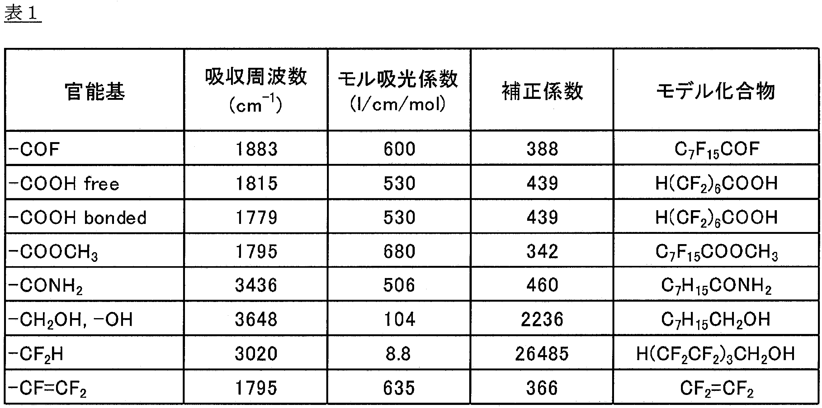
150℃反発力(MPa)=(t2-t1)/t1×E’
t1:圧縮変形させる前の試験片の元の高さ(mm)×50%
t2:圧縮変形させた後の試験片の高さ(mm)
E’:150℃での貯蔵弾性率(MPa)
ジノルマルプロピルパーオキシジカーボネート、ジイソプロピルパーオキシジカーボネート、ジsec-ブチルパーオキシジカーボネート、ジ-2-エトキシエチルパーオキシジカーボネートなどのジアルキルパーオキシカーボネート類;
t-ブチルパーオキシイソブチレート、t-ブチルパーオキシピバレートなどのパーオキシエステル類;
ジt-ブチルパーオキサイドなどのジアルキルパーオキサイド類;
ジ[フルオロ(またはフルオロクロロ)アシル]パーオキサイド類;
などが代表的なものとしてあげられる。
食品包装用フィルム、食品製造工程で使用する流体移送ラインのライニング材、パッキン、シール材、シート等の食品製造装置用流体移送部材;
薬品用の薬栓、包装フィルム、薬品製造工程で使用される流体移送ラインのライニング材、パッキン、シール材、シート等の薬液移送部材;
化学プラントや半導体工場の薬液タンクや配管の内面ライニング部材;
自動車の燃料系統並びに周辺装置に用いられるO(角)リング・チューブ・パッキン、バルブ芯材、ホース、シール材等、自動車のAT装置に用いられるホース、シール材等の燃料移送部材;
自動車のエンジン並びに周辺装置に用いられるキャブレターのフランジガスケット、シャフトシール、バルブステムシール、シール材、ホース等、自動車のブレーキホース、エアコンホース、ラジエーターホース、電線被覆材等のその他の自動車部材;
半導体製造装置のO(角)リング、チューブ、パッキン、バルブ芯材、ホース、シール材、ロール、ガスケット、ダイヤフラム、継手等の半導体装置用薬液移送部材;
塗装設備用の塗装ロール、ホース、チューブ、インク用容器等の塗装・インク用部材;
飲食物用のチューブ又は飲食物用ホース等のチューブ、ホース、ベルト、パッキン、継手等の飲食物移送部材、食品包装材、ガラス調理機器;
廃液輸送用のチューブ、ホース等の廃液輸送用部材;
高温液体輸送用のチューブ、ホース等の高温液体輸送用部材;
スチーム配管用のチューブ、ホース等のスチーム配管用部材;
船舶のデッキ等の配管に巻き付けるテープ等の配管用防食テープ;
電線被覆材、光ファイバー被覆材、太陽電池の光起電素子の光入射側表面に設ける透明な表面被覆材および裏面剤等の各種被覆材;
ダイヤフラムポンプのダイヤフラムや各種パッキン類等の摺動部材;
農業用フィルム、各種屋根材・側壁等の耐侯性カバー;
建築分野で使用される内装材、不燃性防火安全ガラス等のガラス類の被覆材;
家電分野等で使用されるラミネート鋼板等のライニング材;
各単量体単位の含有量は、NMR分析装置(たとえば、ブルカーバイオスピン社製、AVANCE300 高温プローブ)により測定した。
ASTM D1238に従って、メルトインデクサーG-01(東洋精機製作所社製)を用いて、372℃、5kg荷重下で内径2.1mm、長さ8mmのノズルから10分間あたりに流出するポリマーの質量(g/10分)を求めた。
共重合体のペレットを、コールドプレスにより成形して、厚さ0.25~0.30mmのフィルムを作製した。このフィルムをフーリエ変換赤外分光分析装置〔FT-IR(Spectrum One、パーキンエルマー社製)〕により40回スキャンし、分析して赤外吸収スペクトルを得、完全にフッ素化されて官能基が存在しないベーススペクトルとの差スペクトルを得た。この差スペクトルに現れる特定の官能基の吸収ピークから、下記式(A)に従って試料における炭素原子1×10⁶個あたりの官能基数Nを算出した。
N=I×K/t (A)
I:吸光度
K:補正係数
t:フィルムの厚さ(mm)
参考までに、本開示における官能基について、吸収周波数、モル吸光係数および補正係数を表2に示す。モル吸光係数は低分子モデル化合物のFT-IR測定データから決定したものである。
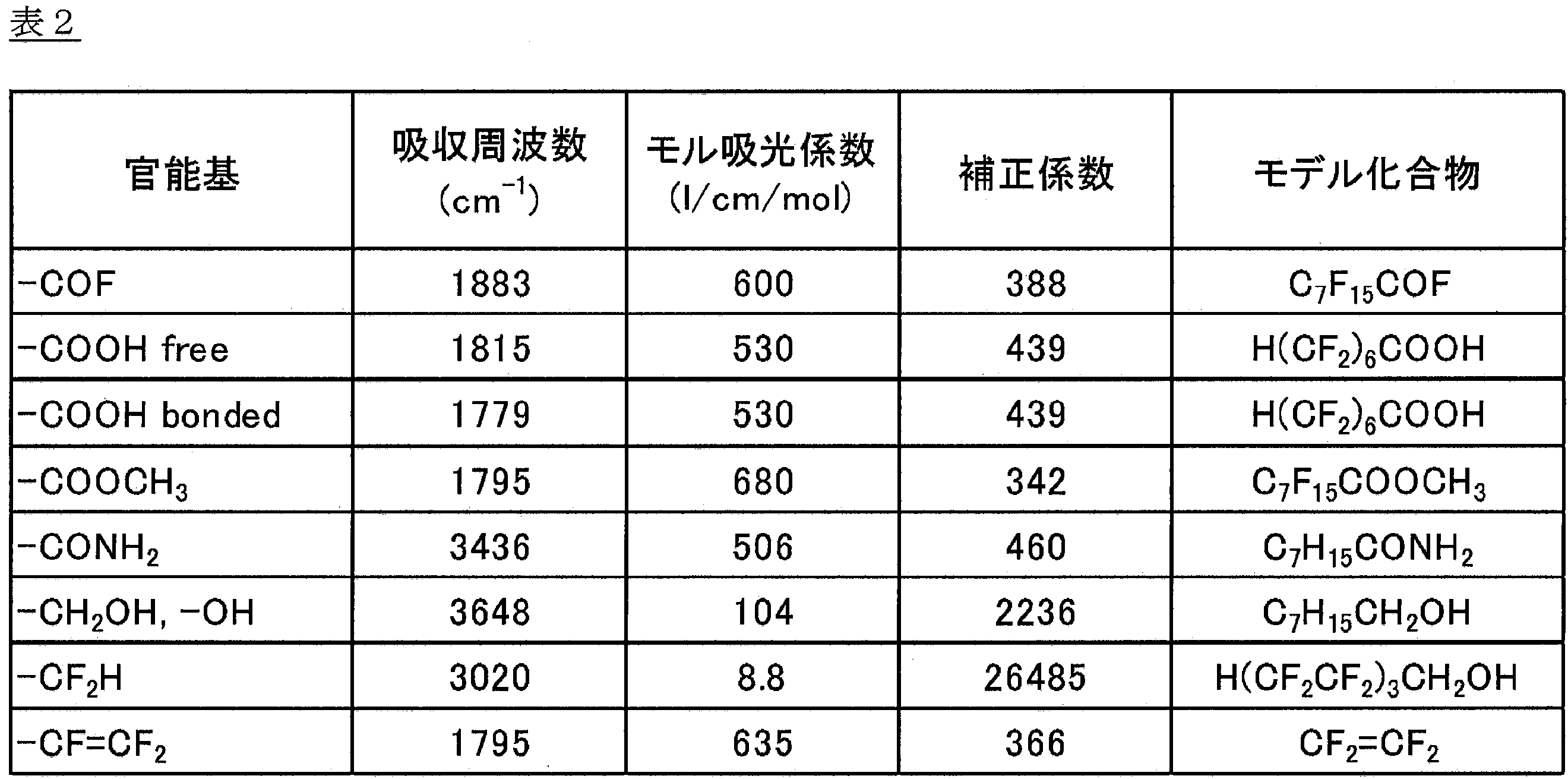
示差走査熱量計(商品名:X-DSC7000、日立ハイテクサイエンス社製)を用いて、昇温速度10℃/分で200℃から350℃までの1度目の昇温を行い、続けて、冷却速度10℃/分で350℃から200℃まで冷却し、再度、昇温速度10℃/分で200℃から350℃までの2度目の昇温を行い、2度目の昇温過程で生ずる溶融曲線ピークから融点を求めた。
174L容積のオートクレーブに純水26.6Lを投入し、充分に窒素置換を行った後、パーフルオロシクロブタン30.4kgとパーフルオロ(プロピルビニルエーテル)(PPVE)0.89kg、メタノール0.21kgとを仕込み、系内の温度を35℃、攪拌速度を200rpmに保った。次いで、テトラフルオロエチレン(TFE)を0.58MPaまで圧入した後、ジ-n-プロピルパーオキシジカーボネートの50%メタノール溶液0.010kgを投入して重合を開始した。重合の進行とともに系内圧力が低下するので、TFEを連続供給して圧力を一定にし、PPVEをTFEの供給1kg毎に0.034kg追加して5時間重合を継続した。TFEを放出して、オートクレーブ内を大気圧に戻した後、得られた反応生成物を水洗、乾燥して15kgの粉末を得た。
PPVEを1.01kg、メタノールを0.22kg、PPVEをTFEの供給1kg毎に0.037kg追加、重合時間を5.5時間に変更した以外は、実施例1と同様にして、フッ素化したペレットを得た。結果を表3に示す。
174L容積のオートクレーブに純水51.8Lを投入し、充分に窒素置換を行った後、パーフルオロシクロブタン40.9kgとパーフルオロ(プロピルビニルエーテル)(PPVE)1.29kg、メタノール4.23kgとを仕込み、系内の温度を35℃、攪拌速度を200rpmに保った。次いで、テトラフルオロエチレン(TFE)を0.64MPaまで圧入した後、ジ-n-プロピルパーオキシジカーボネートの50%メタノール溶液0.026kgを投入して重合を開始した。重合の進行とともに系内圧力が低下するので、TFEを連続供給して圧力を一定にし、PPVEをTFEの供給1kg毎に0.033kg追加投入した。TFEの追加投入量が40.9kgに達したところで重合を終了させた。未反応のTFEを放出して、オートクレーブ内を大気圧に戻した後、得られた反応生成物を水洗、乾燥して42.3kgの粉末を得た。
PPVEを1.60kg、メタノールを4.70kg、PPVEをTFEの供給1kg毎に0.038kg追加に変更し、42.5kgの粉末を得た以外は、実施例3と同様にして、フッ素化したペレットを得た。結果を表3に示す。
174L容積のオートクレーブに純水51.8Lを投入し、充分に窒素置換を行った後、パーフルオロシクロブタン40.9kgとパーフルオロ(プロピルビニルエーテル)(PPVE)1.36kg、メタノール6.14kgとを仕込み、系内の温度を35℃、攪拌速度を200rpmに保った。次いで、テトラフルオロエチレン(TFE)を0.64MPaまで圧入した後、ジ-n-プロピルパーオキシジカーボネートの50%メタノール溶液0.026kgを投入して重合を開始した。重合の進行とともに系内圧力が低下するので、TFEを連続供給して圧力を一定にし、PPVEをTFEの供給1kg毎に0.034kg追加投入した。TFEの追加投入量が40.9kgに達したところで重合を終了させた。未反応のTFEを放出して、オートクレーブ内を大気圧に戻した後、得られた反応生成物を水洗、乾燥して41.0kgの粉末を得た。
PPVEを0.97kg、メタノールを0.12kg、PPVEをTFEの供給1kg毎に0.036kg追加に変更した以外は、実施例1と同様にして、フッ素化したペレットを得た。結果を表3に示す。
PPVEを0.97kg、メタノールを0.23kg、PPVEをTFEの供給1kg毎に0.036kg追加、重合時間を5.5時間に変更した以外は、実施例1と同様にして、フッ素化していないペレットを得た。結果を表3に示す。
PPVEを0.59kg、メタノールを6.50kg、PPVEをTFEの供給1kg毎に0.021kg追加投入に変更し、乾燥粉末41.1kgを得た以外は、比較例1と同様にして、フッ素化したペレットを得た。結果を表3に示す。
PPVEを2.05kg、メタノールを2.80kg、PPVEをTFEの供給1kg毎に0.046kg追加投入に変更し、乾燥粉末42.8kgを得た以外は、比較例1と同様にして、フッ素化したペレットを得た。結果を表3に示す。
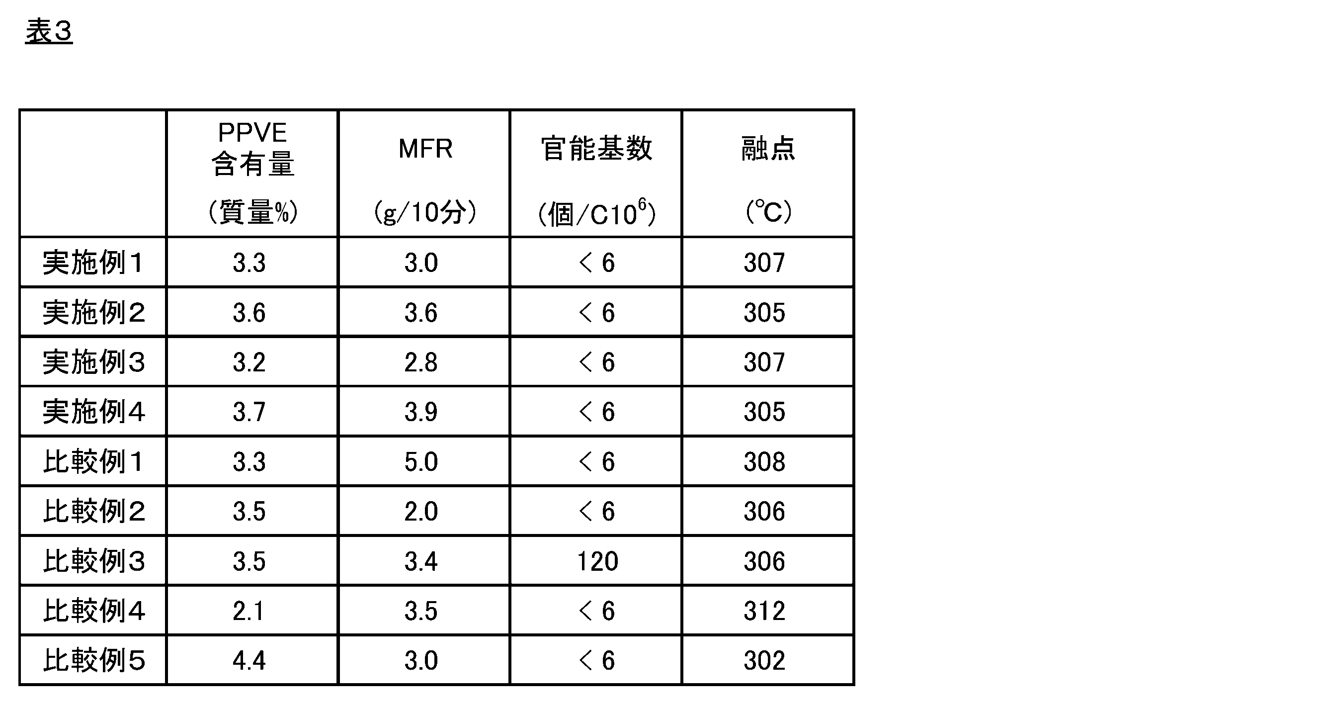
上記ペレットおよびヒートプレス成形機を用いて、厚さ約1.0mmのシートを作製した。ヘイズメーター(商品名:NDH7000SP、日本電色工業株式会社製)を用いて、JIS K 7136に従い、純水を入れた石英セルにシートを浸し、ヘイズ値を測定した。
ペレットおよびヒートプレス成形機を用いて、厚さ約0.2mmのシート状試験片を作製した。試験カップ(透過面積12.56cm2)内に水を18g入れ、シート状試験片で覆い、PTFEガスケットを挟んで締め付け、密閉した。シート状試験片と水が接するようにして、温度95℃で30日間保持した後取出し、室温で2時間放置後に質量減少量を測定した。次式により、水蒸気透過度(g・cm/m2)を測定した。
水蒸気透過度(g・cm/m2)=質量減少量(g)×シート状試験片の厚さ(cm)/透過面積(m2)
DVA-220(アイティー計測制御社製)を用いた動的粘弾性測定を行い求めた。サンプル試験片として、長さ25mm、幅5mm、厚み0.2mmのヒートプレス成形シートを用いて、昇温速度2℃/分、周波数10Hz条件下で、30℃~250℃の範囲で測定を行い、150℃の貯蔵弾性率(MPa)を読み取った。
復元量の測定は、ASTM D395またはJIS K6262:2013に記載の方法に準じた。
復元量(mm)=t2-t1
t1:スペーサの高さ(mm)
t2:圧縮装置から取り外した試験片の高さ(mm)
上記の試験においては、t1=3mmである。
150℃での圧縮試験の結果と150℃における貯蔵弾性率測定の結果から、次式により150℃反発力を求めた。
150℃反発力(MPa)=(t2-t1)/t1×E’
t1:スペーサの高さ(mm)
t2:圧縮装置から取り外した試験片の高さ(mm)
E’:150℃での貯蔵弾性率(MPa)
150℃における反発力が大きい成形体は、高温でも変形しにくく、シール性にも優れている。
φ14mm押出機(井元製作所製)およびTダイを用いて、ペレットを成形し、フィルムを作製した。押出成形条件は以下の通りである。
a)巻き取り速度:0.4m/分
b)ロール温度:120℃
c)フィルム幅:70mm
d)厚み:0.25mm
e)押出条件:
・シリンダ軸径=14mm,L/D=20の単軸押出成形機
押出機の設定温度:バレル部C-1(330℃)、バレル部C-2(350℃)、バレル部C-3(370℃)、Tダイ部(380℃)
上記ペレットを用いて、30mmφ電線被覆成形機(田辺プラスチック機械社製)により、導体径1.00mmの導体上に、下記被覆厚みで押出被覆し、被覆電線を得た。電線被覆押出成形条件は以下の通りである。
a)心導体:軟鋼線導体径1.00mm
b)被覆厚み:0.50mm
c)被覆電線径:2.00mm
d)電線引取速度:7m/分)
e)押出条件:
・シリンダー軸径=20mm,L/D=22の単軸押出成形機
・ダイ(内径)/チップ(外径)=30.0mm/10.0mm
押出機の設定温度:バレル部C-1(330℃)、バレル部C-2(360℃)、バレル部C-3(375℃)、ヘッド部H(390℃)、ダイ部D-1(405℃)、ダイ部D-2(395℃)。心線予備加熱は80℃に設定した。
外径測定器(Zumbach社製ODAC18XY)を用いて、得られた被覆電線の外径を1時間連続で測定した。測定された外径値のうち、所定の外径値(2.00mm)よりも最も大きく乖離した外径値の小数点3桁目を四捨五入することにより、外径の変動値を求めた。所定の外径(2.00mm)に対する、所定の外径と、外径の変動値との差の絶対値の割合(外径の変動率)を算出し、以下の基準により評価した。
(外径の変動率(%))=|(外径の変動値)-(所定の外径)|/(所定の外径)×100
±1%:外径の変動率が1%以下である
±2%:外径の変動率が1%超2%以下である
×:外径の変動率が2%超である
φ30mm押出機(田辺プラスチックス機械製)を用いて、ペレットを押出成形し、外径10.0mm、肉厚1.0mmのチューブを得た。押出成形条件は以下の通りである。
a)ダイ内径:25mm
b)マンドレル外径:13mm
c)サイジングダイ内径:10.5mm
d)引取り速度:0.4m/分
e)外径:10.0mm
f)肉厚:1.0mm
g)押出条件:
・シリンダー軸径=30mm,L/D=22の単軸押出成形機
押出機の設定温度:バレル部C-1(350℃)、バレル部C-2(370℃)、バレル部C-3(380℃)、ヘッド部H-1(390℃)、ダイ部D-1(390℃)、ダイ部D-2(390℃)
得られたチューブを観察し、以下の基準により評価した。チューブの外観は、目視により確認した。
○:外観が良好である
×:断面が円形になっておらず、扁平していたり偏肉が観られるなど、外観が不良である
ペレットおよびヒートプレス成形機を用いて、厚さ約0.2mmのシート状試験片を作製し、これから10cm×10cmの試験片を切り出した。テーバー摩耗試験機(No.101 特型テーバー式アブレーションテスター、安田精機製作所社製)の試験台に作製した試験片を固定し、試験片表面温度150℃、荷重500g、摩耗輪CS-10(研磨紙#240で20回転研磨したもの)、回転速度60rpmの条件で、テーバー摩耗試験機を用いて摩耗試験を行った。1000回転後の試験片重量を計量し、同じ試験片でさらに5000回転試験後に試験片重量を計量した。次式により、摩耗量を求めた。
摩耗量(mg)=M1-M2
M1:1000回転後の試験片重量(mg)
M2:5000回転後の試験片重量(mg)
ペレットおよびヒートプレス成形機を用いて、厚さ約0.1mmのシート状試験片を作製した。得られた試験片を用い、JIS K7126-1:2006に記載の方法に従って、差圧式ガス透過度計(L100-5000型ガス透過度計、Systech illinois社製)を用いて、二酸化炭素透過度の測定を行った。透過面積50.24cm2、試験温度70℃、試験湿度0%RHでの二酸化炭素透過度の数値を得た。得られた二酸化炭素透過度と試験片厚みを用いて、次式より二酸化炭素透過係数を算出した。
二酸化炭素透過係数(cm3・mm/(m2・24h・atm))=GTR×d
GTR:二酸化炭素透過度(cm3/(m2・24h・atm))
d:試験片厚み(mm)
ペレットおよびヒートプレス成形機を用いて、厚さ約0.2mmのシート状試験片を作製した。試験カップ(透過面積12.56cm2)内に酢酸エチルを10g入れ、シート状試験片で覆い、PTFEガスケットを挟んで締め付け、密閉した。シート状試験片と酢酸エチルが接するようにして、温度60℃で45日間保持した後取出し、室温で1時間放置後に質量減少量を測定した。次式により、酢酸エチル透過度(g・cm/m2)を求めた。
酢酸エチル(g・cm/m2)=質量減少量(g)×シート状試験片の厚さ(cm)/透過面積(m2)
ペレットおよびヒートプレス成形機を用いて、厚さ約3mmのシート状試験片を作製し、これから80×10mmの試験片を切り出し、電気炉にて100℃で20時間加熱した。得られた試験片を用いた以外は、JIS K-K 7191-1に記載の方法に準じて、ヒートディストーションテスター(安田精機製作所社製)にて、試験温度30~150℃、昇温速度120℃/時間、曲げ応力1.8MPa、フラットワイズ法の条件にて試験を行った。次式により荷重たわみ率を求めた。95℃での荷重たわみ率が小さいシートは、高温時剛性に優れている。
荷重たわみ率(%)=a2/a1×100
a1:試験前の試験片厚み(mm)
a2:95℃でのたわみ量(mm)
日立ハイテクサイエンス社製TMA-7100を用いて引張クリープ歪を測定した。ペレットおよびヒートプレス成形機を用いて、厚さ約0.1mmのシートを作製し、シートから幅2mm、長さ22mmのサンプルを作製した。サンプルを治具間距離10mmで測定治具に装着した。サンプルに対して、断面荷重が2.41N/mm2になるように荷重を負荷し、240℃に放置し、試験開始後90分の時点から試験開始後300分の時点までのサンプルの長さの変位(mm)を測定し、初期のサンプル長(10mm)に対する長さの変位(mm)の割合(引張クリープ歪(%))を算出した。240℃、300分間の条件で測定する引張クリープ歪(%)が小さいシートは、非常に高温の環境中で引張荷重が負荷されても伸びにくく、高温引張クリープ特性に優れている。
ペレットおよびヒートプレス成形機を用いて、直径13mm、高さ約6.5mmの成形体を作製した。得られた成形体を切削して、高さ6.3mmの試験片を作製した。作製した試験片をSUS製シャーレに入れ、電気炉にて330℃で30分間加熱後、試験片を入れたシャーレごと水冷した。取り出した試験片のシャーレに接していた面(底面)の直径をノギスで計測し、次式により、底面積増加率を算出した。
底面積増加率(%)={加熱後試験片底面積(mm2)―加熱前試験片底面積(mm2)}/加熱前試験片底面積(mm2)×100
底面積増加率が低いほど、成形体が溶融時に自重により変形しにくいことを意味する。底面積増加率が低い成形体を与える共重合体は、押出成形法によって共重合体を成形して、厚いシートや大型のパイプを作製する場合であっても、溶融状態の成形体が変形しにくく、冷却固化した後に所望の形状の成形体が得られる点で優れている。
押出圧力は、ツインキャピラリーレオメーターRHEOGRAPH 25(Goettfert社製)を用いて測定した。メインダイス内径1mm、L/D=16、サブダイス内径1mm、L/D<1、を用いて、測定温度390℃、ペレット投入後余熱時間10分、せん断速度20sec-1で10分間押出した後のシリンダー内圧力値をバーグレー補正することによって押出圧力とした。押出圧力が低い共重合体は、押出成形性、射出成形性などの成形性に優れている。
ペレット25gを3重量%過酸化水素水溶液50gに浸漬し、電気炉にて90℃、20時間加熱し、さらに滅菌機で121℃、1時間加熱後、室温まで冷却した。水溶液からペレットを取り出し、残った水溶液にTISAB溶液(10)(関東化学社製)を添加し、得られた水溶液中のフッ素イオン濃度をフッ素イオンメーターにて測定した。得られた測定値から、下記式に従って、ペレット重量当たりのフッ素イオン濃度(溶出フッ素イオン量)を算出した。
溶出フッ素イオン量(質量ppm)=測定値(質量ppm)×水溶液量(g)/ペレット重量(g)
ペレットを、溶融成形することにより、直径2mmの円柱状の試験片を作製した。作製した試験片を、関東電子応用開発社製6GHz用空洞共振器にセットし、アジレントテクノロジー社製ネットワークアナライザで測定した。測定結果を、ネットワークアナライザに接続されたPC上の関東電子応用開発社製解析ソフト「CPMA」で解析することにより、20℃、6GHzでの誘電正接(tanδ)を求めた。

Claims (7)
- テトラフルオロエチレン単位およびパーフルオロ(プロピルビニルエーテル)単位を含有し、
パーフルオロ(プロピルビニルエーテル)単位の含有量が、全単量体単位に対して、2.8~3.9質量%であり、
372℃におけるメルトフローレートが、2.8~4.0g/10分であり、
官能基数が、主鎖炭素数106個あたり、20個以下である
共重合体。 - 372℃におけるメルトフローレートが、2.8~3.9g/10分である請求項1に記載の共重合体。
- 請求項1または2に記載の共重合体を含有する押出成形体。
- 請求項1または2に記載の共重合体を含有するブロー成形体。
- 請求項1または2に記載の共重合体を含有するトランスファー成形体。
- 請求項1または2に記載の共重合体を含有する被覆層を備える被覆電線。
- 請求項1または2に記載の共重合体を含有する成形体であって、前記成形体がボトルである成形体。
Priority Applications (3)
| Application Number | Priority Date | Filing Date | Title |
|---|---|---|---|
| EP22759274.8A EP4299465A1 (en) | 2021-02-26 | 2022-01-31 | Copolymer, molded body, extruded body, blow molded body, transfer molded body, and coated electrical wire |
| CN202280016006.0A CN116981702A (zh) | 2021-02-26 | 2022-01-31 | 共聚物、成型体、挤出成型体、吹塑成型体、传递成型体以及被覆电线 |
| US18/451,455 US20230399431A1 (en) | 2021-02-26 | 2023-08-17 | Copolymer, molded body, extruded body, blow molded body, transfer molded body, and coated electrical wire |
Applications Claiming Priority (4)
| Application Number | Priority Date | Filing Date | Title |
|---|---|---|---|
| JP2021031114 | 2021-02-26 | ||
| JP2021-031114 | 2021-02-26 | ||
| JP2021-162081 | 2021-09-30 | ||
| JP2021162081 | 2021-09-30 |
Publications (1)
| Publication Number | Publication Date |
|---|---|
| WO2022181233A1 true WO2022181233A1 (ja) | 2022-09-01 |
Family
ID=83048181
Family Applications (1)
| Application Number | Title | Priority Date | Filing Date |
|---|---|---|---|
| PCT/JP2022/003648 WO2022181233A1 (ja) | 2021-02-26 | 2022-01-31 | 共重合体、成形体、押出成形体、ブロー成形体、トランスファー成形体および被覆電線 |
Country Status (4)
| Country | Link |
|---|---|
| US (1) | US20230399431A1 (ja) |
| EP (1) | EP4299465A1 (ja) |
| JP (1) | JP7137110B2 (ja) |
| WO (1) | WO2022181233A1 (ja) |
Citations (9)
| Publication number | Priority date | Publication date | Assignee | Title |
|---|---|---|---|---|
| JPS4820788B1 (ja) * | 1969-10-27 | 1973-06-23 | ||
| WO2003048214A1 (fr) * | 2001-12-04 | 2003-06-12 | Daikin Industries, Ltd. | Materiau de moulage destine a des articles resistant a l'ozone et articles moules par injection resistant a l'ozone |
| JP2009059690A (ja) * | 2007-08-08 | 2009-03-19 | Daikin Ind Ltd | 被覆電線及び同軸ケーブル |
| JP2013177574A (ja) * | 2012-02-01 | 2013-09-09 | Daikin Industries Ltd | 封止材料 |
| WO2017082417A1 (ja) * | 2015-11-13 | 2017-05-18 | 旭硝子株式会社 | 共重合体およびこれを含む組成物 |
| JP2020002341A (ja) | 2018-06-26 | 2020-01-09 | ダイキン工業株式会社 | 成形品およびその製造方法 |
| WO2020090981A1 (ja) * | 2018-11-02 | 2020-05-07 | 三井化学株式会社 | エチレン・α-オレフィン・非共役ポリエン共重合体組成物層を含む積層体およびその用途 |
| JP2020100823A (ja) * | 2018-12-21 | 2020-07-02 | ダイキン工業株式会社 | フルオロポリマー組成物、成形品および射出成形品 |
| JP2021002459A (ja) * | 2019-06-21 | 2021-01-07 | ダイキン工業株式会社 | 平角マグネット線およびコイル |
-
2022
- 2022-01-31 EP EP22759274.8A patent/EP4299465A1/en active Pending
- 2022-01-31 WO PCT/JP2022/003648 patent/WO2022181233A1/ja active Application Filing
- 2022-01-31 JP JP2022012575A patent/JP7137110B2/ja active Active
-
2023
- 2023-08-17 US US18/451,455 patent/US20230399431A1/en active Pending
Patent Citations (9)
| Publication number | Priority date | Publication date | Assignee | Title |
|---|---|---|---|---|
| JPS4820788B1 (ja) * | 1969-10-27 | 1973-06-23 | ||
| WO2003048214A1 (fr) * | 2001-12-04 | 2003-06-12 | Daikin Industries, Ltd. | Materiau de moulage destine a des articles resistant a l'ozone et articles moules par injection resistant a l'ozone |
| JP2009059690A (ja) * | 2007-08-08 | 2009-03-19 | Daikin Ind Ltd | 被覆電線及び同軸ケーブル |
| JP2013177574A (ja) * | 2012-02-01 | 2013-09-09 | Daikin Industries Ltd | 封止材料 |
| WO2017082417A1 (ja) * | 2015-11-13 | 2017-05-18 | 旭硝子株式会社 | 共重合体およびこれを含む組成物 |
| JP2020002341A (ja) | 2018-06-26 | 2020-01-09 | ダイキン工業株式会社 | 成形品およびその製造方法 |
| WO2020090981A1 (ja) * | 2018-11-02 | 2020-05-07 | 三井化学株式会社 | エチレン・α-オレフィン・非共役ポリエン共重合体組成物層を含む積層体およびその用途 |
| JP2020100823A (ja) * | 2018-12-21 | 2020-07-02 | ダイキン工業株式会社 | フルオロポリマー組成物、成形品および射出成形品 |
| JP2021002459A (ja) * | 2019-06-21 | 2021-01-07 | ダイキン工業株式会社 | 平角マグネット線およびコイル |
Also Published As
| Publication number | Publication date |
|---|---|
| JP7137110B2 (ja) | 2022-09-14 |
| EP4299465A1 (en) | 2024-01-03 |
| JP2022132114A (ja) | 2022-09-07 |
| US20230399431A1 (en) | 2023-12-14 |
Similar Documents
| Publication | Publication Date | Title |
|---|---|---|
| JP7185169B2 (ja) | 共重合体、成形体、射出成形体および被覆電線 | |
| JP7137110B2 (ja) | 共重合体、成形体、押出成形体、ブロー成形体、トランスファー成形体および被覆電線 | |
| JP7137108B2 (ja) | 共重合体、成形体、押出成形体およびトランスファー成形体 | |
| JP7137109B2 (ja) | 共重合体、成形体、押出成形体およびトランスファー成形体 | |
| JP7104363B1 (ja) | 共重合体、成形体、押出成形体、ブロー成形体、トランスファー成形体および被覆電線 | |
| JP7157365B2 (ja) | 共重合体、成形体、射出成形体および被覆電線 | |
| JP7177374B2 (ja) | 共重合体、成形体、射出成形体および被覆電線 | |
| JP7177375B2 (ja) | 共重合体、成形体、射出成形体および被覆電線 | |
| JP7185168B2 (ja) | 共重合体、成形体、射出成形体および被覆電線 | |
| JP7157363B2 (ja) | 共重合体、成形体、射出成形体および被覆電線 | |
| JP7177376B2 (ja) | 共重合体、成形体、射出成形体および被覆電線 | |
| JP7157364B2 (ja) | 共重合体、成形体および射出成形体 | |
| JP7104362B1 (ja) | 共重合体、成形体、射出成形体および被覆電線 | |
| WO2022181242A1 (ja) | 共重合体、成形体、押出成形体、ブロー成形体、トランスファー成形体および被覆電線 | |
| WO2022181220A1 (ja) | 共重合体、成形体、射出成形体および被覆電線 | |
| WO2022181221A1 (ja) | 共重合体、成形体、射出成形体および被覆電線 | |
| WO2022181222A1 (ja) | 共重合体、成形体、射出成形体および被覆電線 | |
| WO2022181246A1 (ja) | 共重合体、成形体、射出成形体および被覆電線 |
Legal Events
| Date | Code | Title | Description |
|---|---|---|---|
| 121 | Ep: the epo has been informed by wipo that ep was designated in this application |
Ref document number: 22759274 Country of ref document: EP Kind code of ref document: A1 |
|
| WWE | Wipo information: entry into national phase |
Ref document number: 202280016006.0 Country of ref document: CN |
|
| WWE | Wipo information: entry into national phase |
Ref document number: 2022759274 Country of ref document: EP |
|
| NENP | Non-entry into the national phase |
Ref country code: DE |
|
| ENP | Entry into the national phase |
Ref document number: 2022759274 Country of ref document: EP Effective date: 20230926 |