WO2022181200A1 - Dispositif de guidage d'instrument médical et dispositif d'endoscope - Google Patents
Dispositif de guidage d'instrument médical et dispositif d'endoscope Download PDFInfo
- Publication number
- WO2022181200A1 WO2022181200A1 PCT/JP2022/003292 JP2022003292W WO2022181200A1 WO 2022181200 A1 WO2022181200 A1 WO 2022181200A1 JP 2022003292 W JP2022003292 W JP 2022003292W WO 2022181200 A1 WO2022181200 A1 WO 2022181200A1
- Authority
- WO
- WIPO (PCT)
- Prior art keywords
- tube
- joint
- ring member
- guide device
- medical instruments
- Prior art date
Links
- 238000003780 insertion Methods 0.000 claims description 163
- 230000037431 insertion Effects 0.000 claims description 163
- 239000000463 material Substances 0.000 claims description 58
- 230000002093 peripheral effect Effects 0.000 claims description 43
- 229920005989 resin Polymers 0.000 claims description 29
- 239000011347 resin Substances 0.000 claims description 29
- 239000012530 fluid Substances 0.000 claims description 21
- 239000000853 adhesive Substances 0.000 claims description 14
- 238000007599 discharging Methods 0.000 claims description 9
- 238000004804 winding Methods 0.000 claims description 9
- 239000011248 coating agent Substances 0.000 claims description 5
- 238000000576 coating method Methods 0.000 claims description 5
- 230000002265 prevention Effects 0.000 claims description 4
- 230000000717 retained effect Effects 0.000 claims 1
- 230000003902 lesion Effects 0.000 description 28
- 210000000813 small intestine Anatomy 0.000 description 27
- 210000002429 large intestine Anatomy 0.000 description 24
- 238000010586 diagram Methods 0.000 description 20
- 238000000034 method Methods 0.000 description 20
- 210000001599 sigmoid colon Anatomy 0.000 description 20
- 230000014759 maintenance of location Effects 0.000 description 17
- 238000005452 bending Methods 0.000 description 16
- 230000000968 intestinal effect Effects 0.000 description 15
- 210000001198 duodenum Anatomy 0.000 description 14
- 230000001070 adhesive effect Effects 0.000 description 13
- 230000008961 swelling Effects 0.000 description 13
- 210000001035 gastrointestinal tract Anatomy 0.000 description 11
- 238000012986 modification Methods 0.000 description 10
- 230000004048 modification Effects 0.000 description 10
- 229910052782 aluminium Inorganic materials 0.000 description 8
- XAGFODPZIPBFFR-UHFFFAOYSA-N aluminium Chemical compound [Al] XAGFODPZIPBFFR-UHFFFAOYSA-N 0.000 description 8
- 239000011295 pitch Substances 0.000 description 8
- 210000002784 stomach Anatomy 0.000 description 7
- 240000006829 Ficus sundaica Species 0.000 description 6
- 238000005286 illumination Methods 0.000 description 5
- -1 polypropylene Polymers 0.000 description 5
- 210000003384 transverse colon Anatomy 0.000 description 5
- JOYRKODLDBILNP-UHFFFAOYSA-N Ethyl urethane Chemical compound CCOC(N)=O JOYRKODLDBILNP-UHFFFAOYSA-N 0.000 description 4
- 238000000151 deposition Methods 0.000 description 4
- 230000008021 deposition Effects 0.000 description 4
- 239000013013 elastic material Substances 0.000 description 4
- 229920001971 elastomer Polymers 0.000 description 4
- 239000000835 fiber Substances 0.000 description 4
- 229910001220 stainless steel Inorganic materials 0.000 description 4
- 239000010935 stainless steel Substances 0.000 description 4
- 210000001519 tissue Anatomy 0.000 description 4
- 239000004743 Polypropylene Substances 0.000 description 3
- 230000001174 ascending effect Effects 0.000 description 3
- 230000008602 contraction Effects 0.000 description 3
- 210000003238 esophagus Anatomy 0.000 description 3
- 210000003205 muscle Anatomy 0.000 description 3
- 229920001155 polypropylene Polymers 0.000 description 3
- 210000001187 pylorus Anatomy 0.000 description 3
- 239000004698 Polyethylene Substances 0.000 description 2
- VYPSYNLAJGMNEJ-UHFFFAOYSA-N Silicium dioxide Chemical compound O=[Si]=O VYPSYNLAJGMNEJ-UHFFFAOYSA-N 0.000 description 2
- 230000000694 effects Effects 0.000 description 2
- 239000011888 foil Substances 0.000 description 2
- 230000002496 gastric effect Effects 0.000 description 2
- 239000004033 plastic Substances 0.000 description 2
- 229920003023 plastic Polymers 0.000 description 2
- 229920000139 polyethylene terephthalate Polymers 0.000 description 2
- 239000005020 polyethylene terephthalate Substances 0.000 description 2
- 238000009864 tensile test Methods 0.000 description 2
- 229910000831 Steel Inorganic materials 0.000 description 1
- 238000012937 correction Methods 0.000 description 1
- 238000001035 drying Methods 0.000 description 1
- 239000003365 glass fiber Substances 0.000 description 1
- 239000007769 metal material Substances 0.000 description 1
- 238000011017 operating method Methods 0.000 description 1
- 229920001225 polyester resin Polymers 0.000 description 1
- 239000004645 polyester resin Substances 0.000 description 1
- 229920000573 polyethylene Polymers 0.000 description 1
- 229920001296 polysiloxane Polymers 0.000 description 1
- 229920005749 polyurethane resin Polymers 0.000 description 1
- 238000007788 roughening Methods 0.000 description 1
- 238000007789 sealing Methods 0.000 description 1
- 238000000926 separation method Methods 0.000 description 1
- 239000000377 silicon dioxide Substances 0.000 description 1
- 239000010959 steel Substances 0.000 description 1
- 239000000758 substrate Substances 0.000 description 1
- 229920002803 thermoplastic polyurethane Polymers 0.000 description 1
- 238000001771 vacuum deposition Methods 0.000 description 1
Images


Classifications
-
- A—HUMAN NECESSITIES
- A61—MEDICAL OR VETERINARY SCIENCE; HYGIENE
- A61B—DIAGNOSIS; SURGERY; IDENTIFICATION
- A61B1/00—Instruments for performing medical examinations of the interior of cavities or tubes of the body by visual or photographical inspection, e.g. endoscopes; Illuminating arrangements therefor
- A61B1/00064—Constructional details of the endoscope body
- A61B1/00071—Insertion part of the endoscope body
- A61B1/0008—Insertion part of the endoscope body characterised by distal tip features
- A61B1/00082—Balloons
-
- A—HUMAN NECESSITIES
- A61—MEDICAL OR VETERINARY SCIENCE; HYGIENE
- A61B—DIAGNOSIS; SURGERY; IDENTIFICATION
- A61B1/00—Instruments for performing medical examinations of the interior of cavities or tubes of the body by visual or photographical inspection, e.g. endoscopes; Illuminating arrangements therefor
- A61B1/005—Flexible endoscopes
- A61B1/01—Guiding arrangements therefore
-
- A—HUMAN NECESSITIES
- A61—MEDICAL OR VETERINARY SCIENCE; HYGIENE
- A61B—DIAGNOSIS; SURGERY; IDENTIFICATION
- A61B1/00—Instruments for performing medical examinations of the interior of cavities or tubes of the body by visual or photographical inspection, e.g. endoscopes; Illuminating arrangements therefor
- A61B1/00064—Constructional details of the endoscope body
- A61B1/00071—Insertion part of the endoscope body
- A61B1/00078—Insertion part of the endoscope body with stiffening means
-
- A—HUMAN NECESSITIES
- A61—MEDICAL OR VETERINARY SCIENCE; HYGIENE
- A61B—DIAGNOSIS; SURGERY; IDENTIFICATION
- A61B1/00—Instruments for performing medical examinations of the interior of cavities or tubes of the body by visual or photographical inspection, e.g. endoscopes; Illuminating arrangements therefor
- A61B1/00147—Holding or positioning arrangements
- A61B1/00148—Holding or positioning arrangements using anchoring means
-
- A—HUMAN NECESSITIES
- A61—MEDICAL OR VETERINARY SCIENCE; HYGIENE
- A61B—DIAGNOSIS; SURGERY; IDENTIFICATION
- A61B1/00—Instruments for performing medical examinations of the interior of cavities or tubes of the body by visual or photographical inspection, e.g. endoscopes; Illuminating arrangements therefor
- A61B1/005—Flexible endoscopes
- A61B1/0051—Flexible endoscopes with controlled bending of insertion part
- A61B1/0055—Constructional details of insertion parts, e.g. vertebral elements
-
- G—PHYSICS
- G02—OPTICS
- G02B—OPTICAL ELEMENTS, SYSTEMS OR APPARATUS
- G02B23/00—Telescopes, e.g. binoculars; Periscopes; Instruments for viewing the inside of hollow bodies; Viewfinders; Optical aiming or sighting devices
- G02B23/24—Instruments or systems for viewing the inside of hollow bodies, e.g. fibrescopes
- G02B23/2476—Non-optical details, e.g. housings, mountings, supports
-
- A—HUMAN NECESSITIES
- A61—MEDICAL OR VETERINARY SCIENCE; HYGIENE
- A61M—DEVICES FOR INTRODUCING MEDIA INTO, OR ONTO, THE BODY; DEVICES FOR TRANSDUCING BODY MEDIA OR FOR TAKING MEDIA FROM THE BODY; DEVICES FOR PRODUCING OR ENDING SLEEP OR STUPOR
- A61M25/00—Catheters; Hollow probes
- A61M25/0043—Catheters; Hollow probes characterised by structural features
- A61M2025/0063—Catheters; Hollow probes characterised by structural features having means, e.g. stylets, mandrils, rods or wires to reinforce or adjust temporarily the stiffness, column strength or pushability of catheters which are already inserted into the human body
-
- A—HUMAN NECESSITIES
- A61—MEDICAL OR VETERINARY SCIENCE; HYGIENE
- A61M—DEVICES FOR INTRODUCING MEDIA INTO, OR ONTO, THE BODY; DEVICES FOR TRANSDUCING BODY MEDIA OR FOR TAKING MEDIA FROM THE BODY; DEVICES FOR PRODUCING OR ENDING SLEEP OR STUPOR
- A61M25/00—Catheters; Hollow probes
- A61M25/01—Introducing, guiding, advancing, emplacing or holding catheters
- A61M25/06—Body-piercing guide needles or the like
- A61M25/0662—Guide tubes
- A61M2025/0681—Systems with catheter and outer tubing, e.g. sheath, sleeve or guide tube
-
- A—HUMAN NECESSITIES
- A61—MEDICAL OR VETERINARY SCIENCE; HYGIENE
- A61M—DEVICES FOR INTRODUCING MEDIA INTO, OR ONTO, THE BODY; DEVICES FOR TRANSDUCING BODY MEDIA OR FOR TAKING MEDIA FROM THE BODY; DEVICES FOR PRODUCING OR ENDING SLEEP OR STUPOR
- A61M25/00—Catheters; Hollow probes
- A61M25/0043—Catheters; Hollow probes characterised by structural features
- A61M25/0045—Catheters; Hollow probes characterised by structural features multi-layered, e.g. coated
-
- A—HUMAN NECESSITIES
- A61—MEDICAL OR VETERINARY SCIENCE; HYGIENE
- A61M—DEVICES FOR INTRODUCING MEDIA INTO, OR ONTO, THE BODY; DEVICES FOR TRANSDUCING BODY MEDIA OR FOR TAKING MEDIA FROM THE BODY; DEVICES FOR PRODUCING OR ENDING SLEEP OR STUPOR
- A61M25/00—Catheters; Hollow probes
- A61M25/01—Introducing, guiding, advancing, emplacing or holding catheters
- A61M25/0102—Insertion or introduction using an inner stiffening member, e.g. stylet or push-rod
-
- A—HUMAN NECESSITIES
- A61—MEDICAL OR VETERINARY SCIENCE; HYGIENE
- A61M—DEVICES FOR INTRODUCING MEDIA INTO, OR ONTO, THE BODY; DEVICES FOR TRANSDUCING BODY MEDIA OR FOR TAKING MEDIA FROM THE BODY; DEVICES FOR PRODUCING OR ENDING SLEEP OR STUPOR
- A61M25/00—Catheters; Hollow probes
- A61M25/01—Introducing, guiding, advancing, emplacing or holding catheters
- A61M25/0105—Steering means as part of the catheter or advancing means; Markers for positioning
- A61M25/0133—Tip steering devices
- A61M25/0138—Tip steering devices having flexible regions as a result of weakened outer material, e.g. slots, slits, cuts, joints or coils
-
- A—HUMAN NECESSITIES
- A61—MEDICAL OR VETERINARY SCIENCE; HYGIENE
- A61M—DEVICES FOR INTRODUCING MEDIA INTO, OR ONTO, THE BODY; DEVICES FOR TRANSDUCING BODY MEDIA OR FOR TAKING MEDIA FROM THE BODY; DEVICES FOR PRODUCING OR ENDING SLEEP OR STUPOR
- A61M25/00—Catheters; Hollow probes
- A61M25/01—Introducing, guiding, advancing, emplacing or holding catheters
- A61M25/0105—Steering means as part of the catheter or advancing means; Markers for positioning
- A61M25/0133—Tip steering devices
- A61M25/0155—Tip steering devices with hydraulic or pneumatic means, e.g. balloons or inflatable compartments
Definitions
- the present invention relates to a medical instrument guide device and an endoscope apparatus for guiding a medical instrument such as an insertion section of an endoscope into the body.
- the insertion section of the endoscope (hereinafter also referred to as “endoscope insertion section”) is inserted, for example, along a winding and flexible insertion path such as the upper digestive tract or the lower digestive tract. Therefore, the endoscope insertion section is flexible enough to be inserted along the insertion path.
- the intestinal tract which is an example of the insertion path
- the portion that is not fixed to the body (for example, the sigmoid colon), and even if the insertion portion of the endoscope is pushed in, the portion will deform during the insertion. Therefore, there is a problem that the distal end portion of the insertion portion is difficult to move forward. Further, during treatment with an endoscope, there are cases where a precise operation is performed to remove a lesion by pulling out the treatment instrument from the distal end of the insertion section, but the deformation of the above-mentioned portion may hinder such precise operation.
- Patent Document 1 discloses a guide tube for eliminating unstable operations during insertion and treatment.
- a long muscle body having an engaging surface and a strength retaining member is arranged in a sealed space between a flexible inner tube and an outer tube, and the The fluid is discharged to press the engaging surface against at least one of the inner tube and the outer tube to bring the press state into a press state, and the press state is released by supplying the fluid into the closed space.
- this guide tube it is possible to produce a change in hardness between a flexible state in the bending direction and a highly rigid state.
- a guide tube (a guide device for medical instruments) as in Patent Document 1 ensures a sufficient contact area between the engaging surface of the muscle body and the inner tube or the outer tube when the hardness is changed to a high-rigidity state. difficult to do For this reason, it becomes difficult to maintain the shape of the guide device for medical instruments in a curved shape along the curved portion of the intestinal tract, so there is a problem that the insertability of medical instruments such as an endoscope insertion section or a treatment tool is lowered. be. On the other hand, if the number of muscles is increased, it is possible to secure a sufficient contact area. There is a problem of lowering
- the present invention has been made in view of such circumstances, and an object of the present invention is to provide a medical instrument guide device and an endoscope apparatus capable of improving the insertability of medical instruments.
- the medical instrument guide device of the present invention is a medical instrument guide device for guiding a medical instrument into the body, comprising a flexible outer tube and a flexible outer tube disposed inside the outer tube. a tube body having a flexible inner tube; and a deformable body provided between the outer tube and the inner tube and deformable following the shape of the tube body.
- an intermediate layer provided between the outer tube and the inner tube and capable of contacting the shape-deformable body is provided, and the first contact surface provided on the shape-deformable body and the intermediate layer are provided with and a second contact surface facing the first contact surface, and at least a portion of one of the first contact surface and the second contact surface preferably includes a high friction surface.
- the intermediate layer is preferably provided between the outer tube and the deformable body.
- the high friction surface is preferably provided on the second contact surface.
- the high friction surface is preferably provided on the first contact surface.
- the intermediate layer preferably has a higher elastic modulus than the outer tube and the inner tube.
- the intermediate layer is preferably formed by cylindrically forming a sheet material.
- a fluid supply/discharge means for supplying and discharging fluid to and from the internal space between the outer tube and the inner tube is provided, and when the fluid in the internal space is discharged by the fluid supply/discharge means, In the tube main body, it is preferable that the shape of the shape-variable body is maintained by frictional engagement between the shape-variable body and the intermediate layer via a high-friction surface.
- the first contact surface provided on the deformable body and the second contact surface provided on at least one of the outer tube and the inner tube and facing the first contact surface are provided.
- at least a portion of one of the first contact surface and the second contact surface includes a high friction surface.
- a fluid supply/discharge means for supplying and discharging fluid to and from the internal space between the outer tube and the inner tube is provided, and when the fluid in the internal space is discharged by the fluid supply/discharge means,
- the shape of the shape-variable body is preferably maintained by frictional engagement between the shape-variable body and one of the tubes via a high-friction surface.
- the high-friction surface is preferably a resin layer in which one contact surface is coated with resin.
- the high friction surface is preferably a rough surface formed on one contact surface.
- the high-friction surface is preferably a resin layer in which a rough surface formed on one contact surface is coated with a resin.
- the deformable body preferably has a helical tube formed by spirally winding a belt-like member around the outer circumference of the inner tube.
- the deformable body comprises a plurality of articulation ring members arranged along the axial direction of the tube body, the articulation ring members being axially positioned relative to the outer tube or the inner tube. and a plurality of joint pieces extending in a comb shape from the fixing ring member to at least one side in the axial direction and arranged side by side in the circumferential direction around the axial direction. It is preferred to have a plurality of joint pieces.
- the articulation ring member preferably has a plurality of articulation pieces extending axially on opposite sides from the fixation ring member.
- axially adjacent joint ring members are defined as a first joint ring member and a second joint ring member, and the second joint ring of the first joint ring member
- the joint piece extending toward the member is defined as the first joint piece
- the joint piece extending toward the first joint ring member of the second joint ring member is defined as the second joint piece
- the second joint ring member of the first joint piece The first joint piece end region on the side of and the second joint piece end region of the second joint piece on the side of the first joint ring member are arranged at positions in which axial positions overlap with each other, and in the circumferential direction
- the positions are arranged in staggered positions.
- first joint piece and the second joint piece are preferably arranged alternately one by one along the circumferential direction.
- a plurality of first joint piece groups consisting of two or more first joint pieces and a plurality of second joint piece groups consisting of two or more second joint pieces are arranged in the circumferential direction. preferably staggered along the length.
- axially adjacent joint ring members are defined as a first joint ring member and a second joint ring member, and the second joint ring of the first joint ring member
- the joint piece extending toward the member is defined as the first joint piece
- the joint piece extending toward the first joint ring member of the second joint ring member is defined as the second joint piece
- the first joint piece and the second joint piece It is preferable that the positions in the axial direction are shifted from each other and the positions in the circumferential direction are shifted from each other.
- the width of the joint ring member in the axial direction is W1 and the arrangement pitch of the joint ring member in the axial direction is P, it is preferable to satisfy the following expression P ⁇ W1.
- the width of the joint ring member in the axial direction is W1 and the arrangement pitch of the joint ring member in the axial direction is P, it is preferable to satisfy the following equation: P>W1.
- the plurality of joint pieces arranged side by side in the circumferential direction are preferably arranged at regular intervals along the circumferential direction.
- the plurality of fixing ring members be arranged at regular intervals along the axial direction.
- the joint piece is provided between a rectangular piece body elongated in the axial direction and the piece body and the fixing ring member, and is formed narrower than the piece body. and a connecting member.
- At least one of the outer peripheral surface of the outer tube and the inner peripheral surface of the inner tube preferably has a hydrophilic coating.
- the medical instrument is preferably an endoscope having an insertion section that is inserted into the body.
- the medical instrument guide device preferably has a switching member capable of switching between opening to the atmosphere and inflowing to the atmosphere with respect to the internal space located between the outer tube and the inner tube.
- the tube main body has a body-adhering portion provided at the distal end portion of the tube main body.
- the body-fitting portion is configured by an inflatable and deflatable tube body balloon disposed at the distal end of the tube body.
- the body-fitting section has a suction port arranged at the distal end of the tube body.
- the body-fitting portion has a porous entanglement prevention member that covers the suction port.
- the endoscope apparatus of the present invention includes a medical instrument and the medical instrument guide device of the present invention, wherein the medical instrument is an endoscopic device having an insertion section to be inserted into the body. is a mirror.
- the endoscope preferably has switching means capable of switching between opening to the atmosphere and inflowing to the atmosphere with respect to the internal space located between the outer tube and the inner tube.
- the insertion section can be inserted into the tube body, and in a state in which the insertion section is inserted into the tube body, the body tissue is prevented from being caught between the tube body and the insertion section. It is preferable that a clearance is formed for this purpose.
- the clearance is preferably 4 mm or less.
- the insertion section preferably has an effective length that is 300 mm or more longer than the full length of the tube body.
- the insertion section preferably has an inflatable and contractible balloon for the insertion section provided at the distal end of the insertion section.
- FIG. 1 is an external view of an endoscope apparatus according to a first embodiment of the invention.
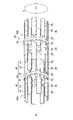
- FIG. 2 is an enlarged cross-sectional view of the main part showing the structure of the guide tube of FIG. 3 is a perspective view showing the structure of a deformable body provided in the guide tube of FIG. 1.
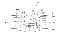
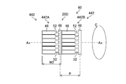
- FIG. 4 is an explanatory diagram schematically showing the arrangement positions of the joint ring members of FIG.
- FIG. 5 is a schematic diagram of a curved tube body.
- FIG. 6 is an explanatory view of treating a lesion using a guide tube.
- FIG. 7 is an explanatory diagram of treating a lesion using only an endoscope.
- FIG. 8 is an explanatory diagram schematically showing the arrangement position of the joint ring member of the guide tube according to the second embodiment.
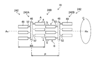
- FIG. 9 is an explanatory diagram schematically showing the arrangement position of the joint ring member of the guide tube according to the third embodiment.
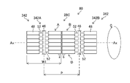
- FIG. 10 is an explanatory view schematically showing the arrangement position of the joint ring member of the guide tube according to the fourth embodiment.
- FIG. 11 is an explanatory view schematically showing the arrangement position of the joint ring member of the guide tube according to the fifth embodiment.
- FIG. 12 is a structural diagram of a helical tube employed in the guide tube of the sixth embodiment.
- FIG. 13 is an explanatory diagram of a helical tube deformed into a curved shape.
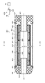
- FIG. 14 is an enlarged sectional view showing the structure of the guide tube according to the seventh embodiment.
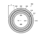
- 15 is a longitudinal cross-sectional view of the guide tube taken along line 15--15 of FIG. 14;
- FIG. 16 is an enlarged cross-sectional view of the main part of the proximal end side of the guide tube shown in FIG. 14.
- FIG. 17 is an enlarged cross-sectional view of the main part of the distal end side of the guide tube shown in FIG. 14.
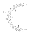
- FIG. FIG. 18 is an external view of a helical tube.
- FIG. 19 is an explanatory view of the helical tube shown in FIG. 18 deformed into a curved shape.
- FIG. 22 is a side view showing a first modification of the helical tube.
- FIG. 23 is an external view showing a second modification of the helical tube.
- FIG. 24 is an external view showing a third modification of the helical tube.
- FIG. 25 is an external view showing a fourth modification of the helical tube.
- FIG. 26 is an external view showing a fifth modification of the helical tube.
- FIG. 27 is a longitudinal sectional view showing the structure of the guide tube according to the eighth embodiment.
- FIG. 28 is a perspective view of an endoscope apparatus according to a second embodiment of the invention.
- FIG. 29 is a cross-sectional view of the guide tube into which the insertion portion is inserted.
- FIG. 30 is a piping diagram when a pump is also used.
- FIG. 31A and 31B are explanatory diagrams showing the operating procedure of the endoscope apparatus shown in FIG. 28.
- FIG. 32A and 32B are explanatory diagrams showing the procedure of the endoscope apparatus shown in FIG. 28.
- FIG. FIG. 33 is a cross-sectional view showing a balloon of the first modified example.
- FIG. 34 is a cross-sectional view showing a balloon of a second modification.
- FIG. 35 is a cross-sectional view showing a balloon of a third modified example.
- FIG. 36 is a cross-sectional view showing a fourth modified balloon.
- FIG. 37 is a cross-sectional view showing a balloon of a fifth modification.
- FIG. 38 is a front view showing the balloon of the sixth modification.
- FIG. 39 is a perspective view of a main part of a tube body to which another form of the body-fitting portion is applied. 40 is a cross-sectional view of the main part of the tube main body shown in FIG. 39.
- FIG. 1 is an external view of an endoscope device 1 according to the first embodiment of the present invention.
- an endoscope apparatus 1 includes a medical device guide device (hereinafter referred to as a “guide tube”) 10 and an endoscope 12 according to the first embodiment.
- FIG. 1 shows a usage pattern in which an insertion portion 14 of an endoscope 12 is inserted through the guide tube 10 .
- the endoscope 12 has an insertion section 14 and a hand operation section 16 , and the base end side of the insertion section 14 is connected to the hand operation section 16 .
- the endoscope 12 having the insertion section 14 is an example of the medical instrument of the present invention.
- the insertion portion 14 is configured by sequentially connecting a distal rigid portion 18, a bending portion 20 and a flexible portion 22 from the distal end side to the proximal end side.
- FIG. 1 shows a state in which the distal end rigid portion 18 and the curved portion 20 protrude from the distal end opening 10A of the guide tube 10 to the outside.
- a pair of illumination windows 24 for illuminating the inside of the body and an observation window 26 for acquiring images of the inside of the body under the illumination from these illumination windows 24 are provided in the distal end rigid portion 18 .
- the distal end rigid portion 18 is provided with a treatment instrument lead-out port (not shown) for leading out a treatment instrument such as forceps or a high-frequency treatment instrument.
- the bending portion 20 is bent in a desired direction by operating an angle knob (not shown) provided on the hand operation portion 16 .
- the flexible portion 22 is composed of a flexible member having flexibility in the bending direction. Note that the configuration of the endoscope 12 is conventionally well known, and detailed illustration and description thereof will be omitted here.
- the guide tube 10 according to the first embodiment will be described below.
- FIG. 2 is an enlarged cross-sectional view of the main part showing the structure of the guide tube 10.
- the guide tube 10 has a double tube structure tube body 34 having a flexible outer tube 30 and a flexible inner tube 32 disposed inside the outer tube 30 .
- the outer tube 30 and the inner tube 32 are made of, for example, a soft resin material that can bend along the curvature of the intestinal tract. Examples of soft resin materials include urethane and polyester resins, but are not limited to these.
- the thickness of the outer tube 30 and the inner tube 32 is, for example, about 100 ⁇ m each, and the thickness of the internal space 36 located between the outer tube 30 and the inner tube 32 is, for example, about 800 ⁇ m. be.
- the thicknesses of the outer tube 30, the inner tube 32, and the inner space 36 are not limited to the thicknesses described above, and the diameter of the insertion portion 14 (see FIG. 1) and the thickness into which the insertion portion 14 is inserted. It is set based on the diameter of the target insertion path, etc.
- the internal space 36 is a space whose cross-sectional shape in a direction orthogonal to the axis Ax of the guide tube 10 is formed in a ring shape (doughnut shape) so as to surround the circumference (perimeter) of the inner tube 32, which will be described later.
- a deformable body 28 is arranged.
- the internal space 36 is formed as a closed space by sealing the outer tube 30 and the inner tube 32 on the distal end side and the proximal end side of the tube main body 34 .
- the guide pipe 10 is connected through a pipe 40 to a pump 38 for supplying and discharging fluid (for example, air) to the internal space 36 .
- the pump 38 and the pipe 40 function as fluid supply/discharge means of the present invention.
- the deformable body 28 is provided between the outer tube 30 and the inner tube 32 (that is, the internal space 36 described above).
- the deformable body 28 is deformable following the shape of the tube main body 34, and has a plurality of joint ring members 42 arranged along the axis Ax direction of the tube main body 34 as described later.
- FIG. 3 is a perspective view showing the structure of the deformable body 28 provided in the guide tube 10.
- FIG. 3 shows two joint ring members 42A and 42B that are adjacent in the direction of the axis Ax among the plurality of joint ring members 42.
- the joint ring member 42 corresponds to the joint ring member of the present invention.
- the joint ring member 42A corresponds to the first joint ring member of the present invention
- the joint ring member 42B corresponds to the second joint ring member of the present invention.
- a plurality of joint ring members 42 constituting the deformable body 28 are arranged at equal intervals along the axis Ax direction of the tube main body 34, and each joint ring member 42 has the same configuration. ing. As shown in FIG. 3, the two joint ring members 42A and 42B adjacent to each other in the direction of the axis Ax are arranged in a circumferential direction C around the direction of the axis Ax in the joint ring members 42A and 42B so that the joint pieces 48, which will be described later, do not interfere with each other. are arranged with their positions shifted from each other.
- the joint ring members 42 (42A, 42B) are composed of a fixed ring member 46 formed in an annular shape so as to surround the circumference (perimeter) of the inner tube 32, and a comb-teeth shape extending from the fixed ring member 46 to both sides in the direction of the axis Ax. It has a plurality of extended articulation pieces 48 .
- a fixed ring member 46 and a plurality of joint pieces 48 are integrally formed of the same material.
- the joint ring member 42 is preferably made of a resin material such as polypropylene resin. Also, the joint ring member 42 may be made of a metal material such as stainless steel.
- the fixing ring member 46 is provided so as to be able to fix the relative position of the outer tube 30 or the inner tube 32 in the direction of the axis Ax.
- the fixing ring member 46 in this embodiment has a fixing piece 49 projecting toward the inner tube 32, and the fixing piece 49 is attached to the outer peripheral surface of the inner tube 32 by a fixing means such as bonding. is fixed with .
- the fixing form of the fixing ring member 46 is not limited to the configuration shown in FIG. A configuration in which the piece 49 protrudes to both the inner tube 32 side and the outer tube 30 side and is fixed to both the inner tube 32 and the outer tube 30 may be employed.
- the plurality of joint pieces 48 extend from the fixed ring member 46 to both sides in the direction of the axis Ax in a comb shape.
- the joint pieces 48 extending to one side from the fixed ring member 46 are arranged at regular intervals along the circumferential direction C around the axis Ax so as to follow the shape (annular shape) of the fixed ring member 46 .
- the joint piece 48 has a piece body 50 and a connecting member 52 .
- the piece main body 50 is formed in an elongated rectangular shape in the direction of the axis Ax.
- the connecting member 52 connects between the piece main body 50 and the fixed ring member 46 .
- the connecting member 52 is narrower than the piece body 50 , and when the tube body 34 is curved along, for example, a curved portion of the intestinal tract, the piece body 50 is attached to the fixing ring member 46 . It has a function to smoothly follow the bending direction of the
- the articulation ring member 42 has a high-friction surface 54 on the surface that contacts the outer tube 30 (hereinafter referred to as "first contact surface”). Specifically, a high friction surface 54 is provided on the first contact surfaces of both the fixed ring member 46 and the articulation piece 48 that constitute the articulation ring member 42 .
- first contact surface a high friction surface 54 is provided on the first contact surfaces of both the fixed ring member 46 and the articulation piece 48 that constitute the articulation ring member 42 .
- the state of the tube main body 34 changes from the flexible state to the highly rigid state.
- the joint ring member 42 and the outer tube 30 are brought into close contact with each other via the high-friction surface 54 and are frictionally engaged.
- the shape (for example, curved shape) of the shape-variable body 28 is maintained so that it cannot be deformed, so that the shape-retaining force of the tube main body 34 in the high-rigidity state (when hardened) is enhanced.
- the shape retention of the deformable body 28 is released, so that the tube main body 34 is made flexible from the high-rigidity state (hardened state). It changes state (uncured state, softened state).
- the high-friction surface described in this specification refers to a surface with a higher coefficient of friction than a contact surface on which no high-friction surface is formed.
- the friction coefficient of the high-friction surface can be measured, for example, by the method described in JISP8147:2010 or by a method based thereon.
- This high-friction surface has a higher coefficient of friction than the outer peripheral surface of the outer tube 30 and the inner peripheral surface of the inner tube 32 .
- the non-deformable described in this specification means that the shape of the deformable body 28 is fixed when the air in the internal space 36 is exhausted.
- the frictional engagement described in this specification means that the respective contact surfaces are engaged with frictional force.
- This frictional force is the frictional force generated when the respective contact surfaces come into contact with each other in the radial direction of the tube body 34 when the tube body 34 is viewed from the direction of the axis Ax.
- each contact surface is formed in a substantially circular shape when viewed from the direction of the axis Ax. Specific examples of the high-friction surface are described below.
- a resin layer obtained by coating the first contact surface of the joint ring member 42 with resin can be exemplified.
- a resin such as silicone having a high coefficient of friction, for example.
- the high friction surface 54 the rough surface formed on the first contact surface can be exemplified. It is formed by applying to Furthermore, as another aspect of the high friction surface 54, an aspect in which the resin layer coated on the first contact surface is roughened, and an aspect in which the roughened surface is coated with resin after roughening the first contact surface are also exemplified. can.
- the surface in contact with the inner peripheral surface of the outer tube 30 was illustrated as the first contact surface of the joint ring member 42 provided with the high friction surface 54 .
- a high friction surface 54 may be provided on the surface (first contact surface) in contact with the outer peripheral surface of the tube 32 .
- the high-friction surface 54 may be provided on the surface of at least one of the outer tube 30 and the inner tube 32 that is in contact with the tube. For example, even if the high-friction surface 54 is provided on the surface in contact with the inner tube 32, the frictional force between the articulation ring member 42 and the inner tube 32 is increased to increase the shape retention force of the tube body 34 during hardening. be able to.
- high friction surfaces 54 may be provided on the respective surfaces in contact with the outer tube 30 and the inner tube 32 . Furthermore, in the present embodiment, as a preferred mode, the high friction surface 54 is provided on both the fixed ring member 46 and the joint piece 48 . and at least one of the joint pieces 48 . When the high friction surface 54 is provided on either the fixed ring member 46 or the joint piece 48, it is preferable to provide the high friction surface 54 on the joint piece 48. Compared to the mode in which 54 is provided, it is possible to obtain the effect of increasing the shape retention force of the tube main body 34 at the time of hardening.
- the high-friction surface 54 may be provided on the inner peripheral surface of the outer tube 30 and on the surface (second contact surface) in contact with the joint ring member 42 , or on the outer peripheral surface of the inner tube 32 . , may be provided on the surface (second contact surface) in contact with the joint ring member 42 . Furthermore, it may be provided on both the outer tube 30 and the inner tube 32 .
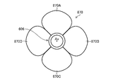
- FIG. 4 is an explanatory view schematically showing relative arrangement positions of the joint ring members 42A and 42B shown in FIG. An example of the arrangement positions of the joint ring members 42A and 42B shown in FIG. 3 will be described below with reference to FIG.
- the joint piece 48 extending from the joint ring member 42A toward the joint ring member 42B will be referred to as a first joint piece A
- the joint ring member 42A of the joint ring member 42B will be referred to as a first joint piece A
- the joint piece 48 extending to the side will be referred to as a second joint piece B for explanation.
- the first joint piece end region a of the first joint piece A on the joint ring member 42B side and the second joint piece end region b of the second joint piece B on the joint ring member 42A side are aligned along the axis Ax.
- the positions of the directions are arranged to overlap each other, and the positions of the circumferential direction C are arranged to be shifted from each other. That is, the joint ring members 42A and 42B satisfy P ⁇ W1, where W1 is the width of the joint ring members 42A and 42B in the direction of the axis Ax, and P is the arrangement pitch of the joint ring members 42A and 42B in the direction of the axis Ax. are arranged as Also, the first joint piece A and the second joint piece B are alternately arranged along the circumferential direction C one by one.
- the first joint piece end region a and the second joint piece end located on the inner peripheral side where the radius of curvature of the tube main body 34 is small.
- the first joint piece end region a and the second joint piece end region b which are located on the outer peripheral side of the tube body 34 with a large radius of curvature, move away from each other. move relative to each other.
- the shape-variable body 28 shown in FIG. When the tube main body 34 is hardened in this state, the tube main body 34 is held in the curved shape which is the shape at that time. Also, as shown in FIG.
- the joint ring members 42A and 42B are arranged along the axis Ax direction, so that the tube main body 34 (especially the inner tube 32) is covered with the plurality of joint ring members 42. Therefore, the tube main body 34 can be hardened without buckling.
- the maximum bending shape of the tube main body 34 is defined by the flexibility of the tube main body 34 itself, the gap between the first joint end region a and the second joint end region b in the circumferential direction C, and the like. As a result, the tube body 34 can be bent with flexibility from the straight rod shape shown in FIG.
- the guide tube 10 has a mesh tube (also referred to as braided or braided net) 56 in the inner space 36 of the tube body 34 .
- the mesh tube 56 is arranged in the space between the inner tube 32 and the deformable body 28 in the internal space 36 and covers the outer circumference of the inner tube 32 .
- the mesh tube 56 also prevents the tube body 34 from buckling.
- the mesh tube 56 is not an essential member in the guide tube 10, it is preferable to include the mesh tube 56 from the viewpoint of preventing the buckling described above.
- the tube main body 34 of the guide tube 10 is inserted transanally into the large intestine 500 with the insertion portion 14 of the endoscope 12 inserted therethrough.
- a field of view forward in the insertion direction can be obtained through the illumination window 24 and the observation window 26 of the distal end rigid portion 18 .
- the tube main body 34 and the insertion portion 14 inserted through the tube main body 34 are inserted along the large intestine 500 .
- the insertion portion 14 and the tube main body 34 have flexibility, they are smoothly inserted along the curved shape of the large intestine 500 .
- the pump 38 (see FIG. 1) is operated to suck the air in the internal space 36 from the pipe 40 .
- the tube main body 34 is deformed into a curved shape following the curved shape of the sigmoid colon 502 .
- the deformable body 28 (see FIG. 3) composed of a plurality of joint ring members 42 is deformed into a curved shape following the curved shape of the tube main body 34 (that is, the curved shape of the sigmoid colon).
- each articulation ring member 42 is in intimate contact with the inner tube 32 and the high friction surface 54 of each articulation ring member 42 is in intimate frictional engagement with the outer tube 30 .
- the tube main body 34 hardens in a shape corresponding to the curved shape of the sigmoid colon 502 and the shape is maintained, so that the insertability of the insertion portion 14 into the sigmoid colon 502 is improved.
- the bending portion 20 of the insertion portion 14 is protruded forward from the distal opening 10A of the guide tube 10, and the treatment instrument (not shown) is led forward from the treatment instrument outlet (not shown) of the distal rigid portion 18.
- Treatment of lesion 506 in transverse colon 504 is initiated.
- the distal rigid portion 18 can be positioned at an appropriate treatment position, and as a result, the lesion 506 can be accurately treated. It is possible to take appropriate measures.
- FIG. 7 is a schematic diagram in the case of treating a lesion 506 only with the endoscope 12 without using the guide tube 10, and is an explanatory diagram for comparison with the treatment in FIG.
- the treatment method of FIG. 7 even if the insertion portion 14 is pushed into the large intestine 500, the sigmoid colon 502 is deformed, making it difficult for the distal end hard portion 18 of the insertion portion 14 to move forward. adjustment becomes difficult. As a result, it becomes difficult to treat the lesion 506 accurately.
- the distal end hard portion 18 is It becomes easier to move forward, and adjustment of the position of the distal end rigid portion 18 becomes easier. As a result, the lesion 506 can be appropriately treated.
- the deformable body 28 has a plurality of joint ring members 42 arranged along the axis Ax direction of the tube main body 34, and each joint ring member 42 each have a fixation ring member 46 and a plurality of articulation pieces 48, and on the first contact surface of each articulation ring member 42 (the surface contacting at least one of the outer tube 30 and the inner tube 32). Since the tube body 34 has the high friction surface 54 on the inner side, the shape retention force of the tube body 34 can be increased while maintaining flexibility. Thereby, according to the guide tube 10 according to the first embodiment, the insertability of the insertion portion 14 of the endoscope 12 can be improved.
- each joint ring member 42 since the plurality of joint pieces 48 of each joint ring member 42 are arranged at regular intervals along the circumferential direction C, a uniform shape-retaining force is exerted even when the tube main body 34 is bent in any direction. Obtainable.
- the joint pieces 48 are arranged at regular intervals in the circumferential direction C of the joint pieces 48 is shown. It does not have to be spaced apart. For example, the arrangement intervals of the joint pieces 48 in the circumferential direction C may be changed periodically.
- FIG. 8 is a schematic diagram showing the main configuration of a deformable body 28A provided in the guide tube 60 according to the second embodiment. 8 schematically shows relative arrangement positions of joint ring members 142A and 142B adjacent in the axis Ax direction among the plurality of joint ring members 142 arranged along the axis Ax direction. In addition, the same code
- the first joint piece A and the second joint piece B are arranged along the circumferential direction C.
- the guide tube 60 of the second embodiment has a plurality of first joint piece groups D (in FIG. 8, two first joint piece groups D is shown) and a plurality of second joint piece groups E (one second joint piece group E is shown in FIG. 8) consisting of two second joint pieces B are alternately arranged along the circumferential direction C. at the point where Since other configurations are the same, the description is omitted.
- the tube main body 34 similarly to the guide tube 10, when the tube main body 34 (see FIG. 2) is curved, the first joint piece group D and the second joint piece group D located on the inner peripheral side of the tube main body 34 are bent.
- the joint piece group E moves relatively toward each other, and the first joint piece group D and the second joint piece group E located on the outer peripheral side of the tube body 34 move relatively away from each other. move on.
- the tube main body 34 can be held in a curved shape.
- the shape retention force of the tube main body 34 can be enhanced while maintaining flexibility, so that the insertability of the insertion portion 14 of the endoscope 12 can be improved. can be improved.
- first joint pieces A constitute the first joint piece group D
- second joint pieces B constitute the second joint piece group E
- the first joint piece group D and the second joint piece group E may be configured by three or more first joint piece A and second joint piece B, respectively.
- the first joint piece group D and the second joint piece group E are preferably arranged at equal intervals in the circumferential direction C. As a result, even when the tube main body 34 is bent in any direction, the joint pieces are uniformly curved. A shape retention force can be obtained.
- FIG. 9 is a schematic diagram showing the main configuration of a deformable body 28B provided in a guide tube 70 according to the third embodiment.
- FIG. 9 schematically shows relative arrangement positions of joint ring members 242A and 242B adjacent in the axis Ax direction among the plurality of joint ring members 242 arranged along the axis Ax direction.
- symbol is attached
- each of the first joint piece end region a and the second joint piece end region b moves in the direction of the axis Ax. are arranged at positions overlapping each other, in the guide tube 70 of the third embodiment, the positions of the first joint piece A and the second joint piece B are shifted from each other in the axis Ax direction. It is located in a point.
- the tube main body 34 similarly to the guide tube 10, when the tube main body 34 (see FIG. 2) is curved, the first joint piece end region a located on the inner peripheral side of the tube main body 34 and the second joint piece end region a.
- the two joint end regions b move relatively toward each other, and the first joint end region a and the second joint end region b located on the outer peripheral side of the tube body 34 move away from each other. move relatively to By curing the tube main body 34 in a curved state, the tube main body 34 can be held in a curved shape.
- the guide tube 70 of the third embodiment can increase the shape retention force of the tube main body 34 while maintaining flexibility. can be improved.
- FIG. 10 is a schematic diagram showing the main configuration of a deformable body 28C provided in the guide tube 80 according to the fourth embodiment.
- FIG. 10 schematically shows relative arrangement positions of joint ring members 342A and 342B adjacent in the axis Ax direction among the plurality of joint ring members 342 arranged along the axis Ax direction.
- symbol is attached
- each of the plurality of first joint pieces A and the plurality of second joint pieces B in the circumferential direction C is wide, in the guide tube 80 of the fourth embodiment, the intervals between the plurality of first joint pieces A and the plurality of second joint pieces B in the circumferential direction C are narrow; The point is that the first joint end region a and the second joint end region b overlap each other in the circumferential direction C. As shown in FIG. Since other configurations are the same, the description is omitted.
- the guide tube 80 of the fourth embodiment configured in this way can improve the shape retention force of the tube main body 34 while maintaining flexibility.
- the insertability of 14 can be improved.
- FIG. 11 is a schematic diagram showing the main configuration of a deformable body 28D provided in the guide tube 90 according to the fifth embodiment.
- FIG. 11 schematically shows relative arrangement positions of joint ring members 442A and 442B adjacent in the axis Ax direction among the plurality of joint ring members 442 arranged along the axis Ax direction.
- symbol is attached
- the difference between the fourth embodiment and the fifth embodiment is that in the guide tube 80 of the fourth embodiment, a plurality of joint pieces 48 extend from the fixed ring member 46 to both sides in the axis Ax direction.
- the plurality of joint pieces 48 of each of the joint ring members 442A and 442B extends only to one side (left side in FIG. 11) in the direction of the axis Ax from the fixed ring member 46. at the point. Since other configurations are the same, the description is omitted.
- the width (W2) of the guide tube 90 is smaller than the width (W1) of the guide tube 80 in which the joint pieces 48 extend to both sides, but similarly to the guide tube 80, P>W2. arranged to meet
- the fixed ring member 46 of the joint ring member 442A located on the inner peripheral side of the tube main body 34 and the joint ring member The joint piece 48 of the joint ring member 442B moves relatively toward each other, and the fixed ring member 46 of the joint ring member 442A and the joint piece 48 of the joint ring member 442B located on the outer peripheral side of the tube main body 34 move toward each other. It moves relatively in the direction of separation.
- the guide tube 90 of the fifth embodiment can increase the shape retention force of the tube main body 34 while maintaining flexibility. can be improved.
- FIG. 12 is a schematic diagram showing the essential configuration of a shape-variable body 28E provided in the guide tube 100 according to the sixth embodiment.
- the guide tubes 10, 60, 70, 80, and 90 of the first to fifth embodiments have articulation rings as the deformable bodies 28 and 28A to 28D. While the members 42, 142, 242, 342, 442 are employed, the guide tube 100 of the sixth embodiment employs the helical tube 104 as the deformable body 28E. Since other configurations are the same, the description is omitted.
- the helical tube 104 is formed by spirally winding a band-shaped member 106 and provided on the outer peripheral side of the inner tube (see FIG. 2).
- the helical tube 104 has a high-friction surface 54 on the surface (first contact surface) in contact with at least one of the outer tube 30 and the inner tube 32 shown in FIG. 2 (the outer tube 30 in FIG. 12). is doing.
- the tube main body 34 (see FIG. 2) of the guide tube 100 is such that the helical tube 104 and the outer tube 30 form the high friction surface 54. Frictional engagement is achieved through close contact.
- the shape of the helical tube 104 is maintained so that it cannot be deformed, so that the shape retention force of the tube main body 34 in the high-rigidity state (during hardening) is enhanced. Moreover, since the helical tube 104 has flexibility in the bending direction, it can be deformed into a curved shape as shown in FIG. 13, for example.
- the insertion section 14 inserted through the tube main body 34 are inserted along the large intestine 500, the insertion section 14, the tube main body 34, and the helical tube 104 are each flexible. Therefore, it is smoothly inserted along the curved shape of the large intestine 500 .
- the pump 38 is operated with the tube main body 34 along the curved shape of the sigmoid colon 502 to suck the air in the internal space 36 from the pipe 40, the outer tube 30 and the inner tube 32 are drawn. , are pressed against the spiral tube 104 .
- the helical tube 104 is in intimate contact with the inner tube 32 and the high friction surface 54 of the helical tube 104 is in intimate frictional engagement with the outer tube 30 .
- the tube main body 34 hardens in a shape corresponding to the curved shape of the sigmoid colon 502 and the shape is maintained, so that the insertability of the insertion portion 14 into the sigmoid colon 502 is improved.
- the bending portion 20 of the insertion portion 14 is protruded forward from the distal end opening 10A of the guide tube 100, and the treatment instrument (not shown) is led forward from the treatment instrument outlet (not shown) of the distal end rigid portion 18.
- Treatment of lesion 506 in transverse colon 504 is initiated.
- the distal rigid portion 18 can be positioned at an appropriate treatment position, and as a result, the lesion 506 can be accurately treated. It is possible to take appropriate measures.
- the deformable body 102 has the helical tube 104, and the helical tube 104 has the high-friction surface 54.
- the shape retention force of the main body 34 can be increased.
- the high-friction surface 54 may be provided on the surface of the helical tube 104 in contact with the inner tube 32, and the high-friction surface 54 may be provided on at least one of the outer tube 30 and the inner tube 32.
- FIG. 14 is an enlarged sectional view showing the structure of the guide tube 600 according to the seventh embodiment.
- a part of the guide tube 600 in the direction of the axis Ax is cut away.
- 15 is a schematic cross-sectional view of guide tube 600 taken along line XV-XV in FIG.
- symbol is attached
- the guide tube 600 is a double tube structure tube having a flexible outer tube 602 and a flexible inner tube 604 disposed inside the outer tube 602. It has a body 606 .
- Outer tube 602 and inner tube 604 are each made of, for example, a flexible resin material that can bend along the curvature of the intestinal tract. Urethane (polyurethane resin) can be exemplified as the soft resin material.
- Urethane polyurethane resin
- the outer tube 602 and the inner tube 604 have an elastic modulus of 5 to 5 at an elongation rate of 100%, which is determined by the method described in JISK7161 (tensile test) or a method based thereon.
- a material of about 20 MPa can be applied.
- the thickness of the outer tube 602 and the inner tube 604 is, for example, about 100 ⁇ m to 200 ⁇ m, respectively, and the total thickness of the outer tube 602 and the inner tube 604 is about 200 ⁇ m to 400 ⁇ m. It is preferable that the thickness of the outer tube 602 is thicker than that of the inner tube 604 from the viewpoint of tear prevention.
- the thickness of the internal space 608 located between the outer tube 602 and the inner tube 604 is, for example, about 600 ⁇ m to 800 ⁇ m when the thickness T of the tube body 606 shown in FIG. 15 is about 1 mm (for example, maximum 1 mm). be.
- the thicknesses of the outer tube 602, the inner tube 604, and the inner space 608 are not limited to the thicknesses described above, and the diameter of the insertion section 14 (see FIG. 1) and the thickness into which the insertion section 14 is inserted. It is set based on the diameter of the target insertion path, etc.
- the inner diameter of the inner tube 604 is also set based on the diameter of the insertion section 14, and is, for example, about 6 mm to 16 mm.
- the outer peripheral surface of the outer tube 602 and the inner peripheral surface of the inner tube 604 each have a hydrophilic coat 610 .
- the hydrophilic coat 610 on the outer peripheral surface of the outer tube 602
- the frictional resistance between the outer tube 602 and the large intestine 500 can be reduced.
- the insertability (advancement) of the tube body 606 into the large intestine 500 is improved.
- the hydrophilic coat 610 on the inner peripheral surface of the inner tube 604 the frictional resistance between the inner tube 604 and the insertion portion 14 (see FIG. 1) can be reduced.
- insertability of the insertion portion 14 into the tube main body 606 is improved.
- the hydrophilic coat 610 is not limited to this. It may be formed on at least one of the tubes 604 .
- the hydrophilic coating 610 on both the outer tube 602 and the inner tube 604, the above two effects can be obtained at the same time, which is preferable.
- the internal space 608 is a space whose cross-sectional shape in a direction orthogonal to the axis Ax of the guide tube 600 is formed in a ring shape (doughnut shape) so as to surround the circumference (perimeter) of the inner tube 604, which will be described later.
- a deformable body 612 and an intermediate layer 614 are arranged.
- ring-shaped caps 616 and 618 are adhered to the proximal and distal sides of the tube body 606, respectively, and these caps 616 and 618 seal the outer tube 602 and the inner tube 604. is worn.
- the internal space 608 is formed as a closed space.
- a cap 616 on the base end side of the tube main body 606 is connected via a pipe 40 to a pump 38 for supplying and discharging fluid (for example, air) to and from the internal space 608 .
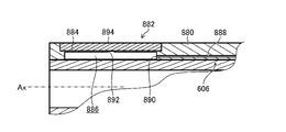
- FIG. 16 is an enlarged cross-sectional view of the main part of the proximal end side of the guide tube 600 shown in FIG.
- cap 616 proximal to tube body 606 is adhered proximally to outer tube 602 via adhesive 620 and proximally to inner tube 604 via adhesive 622 .
- the proximal end sides of the deformable body 612 and the intermediate layer 614 are adhered to the cap 616 with an adhesive 622 .
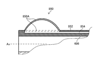
- FIG. 17 is an enlarged cross-sectional view of the main part of the distal end side of the guide tube 600 shown in FIG.
- the cap 618 on the distal side of the tube body 606 is adhered to the distal side of the outer tube 602 via adhesive 624 and to the distal side of the inner tube 604 via adhesive 626 .
- the distal end sides of the deformable body 612 and the intermediate layer 614 are adhered to the cap 618 with an adhesive 626 .
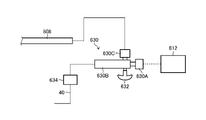
- the proximal end cap 616 has a vent hole 628 that communicates the internal space 608 with the pipe 40 .
- the pipe 40 is connected to the pump 38 via a three-way stopcock 630 .
- the three-way stopcock 630 has a first port 630A connected to the pump 38, a second port 630B connected to the pipe 40, and a third port 630C open to the atmosphere.
- the three-way stopcock 630 also has a cock 632 that is an example of the switching member of the present invention.
- this cock 632 By operating this cock 632 by the practitioner, selectively between an ON mode in which the first port 630A and the second port 630B are communicated and an OFF mode in which the first port 630A and the third port 630C are communicated. Switchable.
- the cock 632 When the cock 632 is switched to ON mode, the pump 38 and the internal space 608 are communicated. As a result, air in the internal space 608 is sucked by the pump 38 and released to the atmosphere, or air (atmosphere) is supplied (flowed) into the internal space 608 by the pump 38 .
- the cock 632 is switched to the OFF mode, the pump 38 and the outside air are communicated. As a result, the supply and exhaust of air to the internal space 608 is stopped.
- the switching operation using the three-way stopcock 630 is performed while the pump 38 is always in operation.
- the switching operation is performed by starting (ON) and stopping (OFF) the pump 38. can also be done.
- the ON/OFF operation of the pump 38 can be performed by a foot switch (not shown), which is another example of the switching member of the present invention.
- an operation button (not shown) for turning the pump 38 ON and OFF may be provided on the hand operation unit 16 of the endoscope 12 (see FIG. 1). This operation button is an example of the switching means of the present invention.
- the deformable body 612 shown in FIGS. 14 and 15 will be described.
- the deformable body 612 is provided between the outer tube 602 and the inner tube 604 (that is, the inner space 608).
- the deformable body 612 is deformable following the shape of the tube main body 606 and has a helical tube 640 arranged along the axis Ax direction of the tube main body 606 .
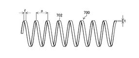
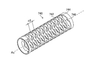
- FIG. 18 is an external view of the helical tube 640.
- the helical tube 640 is formed by spirally winding a band-shaped member 642 and provided on the outer peripheral side of the inner tube 604 (see FIG. 14).
- the helical tube 640 also has a high-friction surface 644 on the surface (outer peripheral surface, first contact surface) in contact with an intermediate layer 614 (see FIG. 14), which will be described later.
- the tube body 606 has a high friction surface 644 between the helical tube 640 and the intermediate layer 614.
- the shape (for example, curved shape) of the helical tube 640 is maintained so that it cannot be deformed, so that the shape retention force of the tube main body 606 in a high-rigidity state (during hardening) is enhanced.
- the helical tube 640 since the helical tube 640 has flexibility in the bending direction, it can be deformed into a curved shape as shown in FIG. 19, for example.
- a belt-shaped member 642 of the helical tube 640 is made of stainless steel (SUS: Steel Use Stainless) as an example. However, it is not limited to this, and any material (for example, plastic) that can be deformed along the shape of the tube main body 606 can be applied.
- the thickness of the belt-shaped member 642 is preferably 300 ⁇ m or less, for example, when the thickness T (see FIG. 15) of the tube body 606 is approximately 1 mm (for example, maximum 1 mm).
- the high-friction surface 644 may be a resin layer obtained by coating the outer peripheral surface (first contact surface) of the helical tube 640 with a resin such as urethane coat or silica coat, a rough surface formed on the first contact surface, or the first contact surface.
- a resin layer in which a resin is coated on a rough surface formed on the substrate can be exemplified.
- it can be formed by immersing the entire helical tube 640 in molten resin and drying it.
- the surface (inner peripheral surface) in contact with the inner tube 604 is also formed with a resin layer that becomes a high-friction surface.
- the helical tube 640 and the inner tube 604 are in close contact with each other through the high-friction surface and are frictionally engaged.
- a high-friction surface is also formed on the outer peripheral surface of the inner tube 604, the spiral tube 640 and the inner tube 604 are in close contact with each other via the high-friction surfaces and are frictionally engaged. In either case, the shape retention force of the tube body 606 is further improved. As shown in FIGS.
- the helical tube 640 configured in this manner is attached to the inner tube 604 by adhesives 622 and 626 at its proximal and distal ends, respectively, at its proximal and distal ends. is glued to As a result, helical tube 640 is firmly adhered to inner tube 604 .
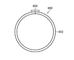
- the intermediate layer 614 shown in FIG. 14 is a sheet material 650 provided between the outer tube 602 and the inner tube 604 and capable of contacting the deformable body 612 (helical tube 640).
- This sheet material 650 is arranged between the outer tube 602 and the helical tube 640 as an example.
- FIG. 20 is a perspective view of the sheet material 650.
- the sheet material 650 is formed in a cylindrical shape and arranged along the axis Ax direction of the tube body 606 (see FIG. 14). Thereby, the outer peripheral surface (first contact surface) of the helical tube 640 ( FIG. 18 ) is covered with the sheet material 650 .
- the sheet material 650 has flexibility so that it can be deformed following the shape of the tube main body 606 (see FIG. 14).
- the sheet material 650 is flexible and has a higher elastic modulus than the outer tube 602 (see FIG. 14) and the inner tube 604 . This elastic modulus will be described later.
- the sheet material 650 is formed by bending a single rectangular sheet 652 into a cylindrical shape and adhering the butted edges with an adhesive 654 as shown in the front view of the sheet material 650 shown in FIG. Configured.
- the form of the sheet material 650 is not limited to a cylindrical shape, and for example, the sheet 652 may be bent into a C-shape, or a plurality of strip-shaped sheets may be combined with the outer tube 602 and the helical tube 130 . It may be in a form in which it is inserted between.
- the sheet material 650 is used as the intermediate layer 614, but it is not limited to this. A member such as a mesh or wire can also be applied. The sheet material 650 applied as the intermediate layer 614 will be described below.
- the sheet material 650 is made of resin such as urethane, for example. However, it is not limited to this, and for example, an aluminum deposition film can also be applied.
- the aluminum deposition film is obtained by vacuum deposition (thermocompression bonding) of aluminum (aluminum foil) on the surface of the base film.
- an aluminum deposition film as the sheet material 650, the rigidity of the sheet material 650 can be increased.
- PET polyethylene terephthalate
- PE polyethylene
- the sheet material 650 preferably has a higher elastic modulus than the outer tube 602 and the inner tube 604, as determined by a method described in JISK7161 (tensile test) or a method based thereon.
- the sheet material 650 can reinforce the outer tube 602 and the inner tube 604 . That is, the tensile strength and tensile stiffness of tube body 606 are enhanced by sheet material 650 .
- the advanceability of the tube main body 606 is improved when the tube main body 606 is not hardened (during the flexible state).
- a material with an optimum elastic modulus can be selected by using a combination of various cloths and films on an aluminum vapor-deposited film or an aluminum foil.
- the thickness of the sheet material 650 is preferably 300 ⁇ m or less, for example, when the thickness of the tube body 606 is approximately 1 mm (for example, maximum 1 mm). However, from the viewpoint of rigidity, it is preferable that the outer tube 602 and the inner tube 604 are thicker. Further, when an aluminum deposition film is applied as the sheet material 650, the rigidity of the sheet material 650 can be changed by changing the base film. As a result, it is possible to tune the hardness of the tube main body 606 when it is not hardened to a hardness suitable for the lower digestive tract such as the large intestine or the upper digestive tract such as the esophagus.
- the sheet material 650 has a high friction surface 656 on the surface (inner peripheral surface, second contact surface) in contact with the helical tube 640 (see FIG. 17).
- the tube body 606 provides a high frictional force between the helical tube 640 (see FIG. 17) and the sheet material 650 respectively.
- the surfaces 644 , 656 are in intimate frictional engagement.
- the shape (for example, curved shape) of the helical tube 640 is maintained so as not to be deformed, so that the shape retention force of the tube main body 606 in the high-rigidity state (during hardening) is further enhanced.
- the first contact surface (outer peripheral surface) of the helical tube 640 and the second contact surface (inner peripheral surface) of the sheet material 650 are both formed with high friction surfaces 644 and 656.
- the high-friction surface may be formed on either one of the contact surfaces, and a form in which it is formed only on the second contact surface (inner peripheral surface) of the sheet material 650 may also be adopted.
- the high-friction surface is preferably formed entirely on one of the contact surfaces, but is not limited to this, and may be formed on a part of either one of the contact surfaces. That is, the high-friction surface may be formed on at least a portion of either one of the contact surfaces.
- the tube body 606 has improved shape retention. Also, the method of forming the high friction surface 656 is the same as that of the high friction surface 644 . Moreover, from the viewpoint of ensuring the flexibility of the tube body 606 when it is not cured, the gap between the helical tube 640 and the sheet material 650 is preferably about 50 ⁇ m to 500 ⁇ m.
- the high-friction surface may be formed on at least a portion of the outer peripheral surface of the sheet material 650 (preferably, the entire outer peripheral surface of the sheet material 650). As a result, the sheet material 650 and the outer tube 602 are brought into close contact with each other through the high-friction surfaces and are frictionally engaged. Also, the high-friction surface may be formed on at least a portion of the inner peripheral surface of outer tube 602 (preferably, the entire inner peripheral surface of outer tube 602). As a result, the sheet material 650 and the outer tube 602 are in close contact with each other through their high friction surfaces and are frictionally engaged. In either case, the shape retention force of the tube body 606 is further improved.
- the insertion section 14 when the tube main body 606 and the insertion section 14 (see FIG. 1) inserted through the tube main body 606 are inserted along the large intestine 500 (see FIG. 6), the insertion section 14, the tube main body 606, and the helical tube 640 are inserted. and the sheet material 650 are each flexible, so that they can be smoothly inserted along the curved shape of the large intestine 500 .
- the pump 38 is operated with the tube main body 606 along the curved shape of the sigmoid colon 502 to suck the air in the internal space 608 from the pipe 40 , the outer tube 602 adheres to the sheet material 650 .
- the inner tube 604 is pressed against the helical tube 640 as it is pressed.
- the high-friction surface 644 of the helical tube 640 is brought into close contact with the high-friction surface 656 of the sheet material 650 to frictionally engage.
- the tube main body 606 is hardened in a shape corresponding to the curved shape of the sigmoid colon 502 and the shape is maintained, so that the insertability of the insertion portion 14 into the sigmoid colon 502 is improved.
- the tube main body 606 is cured in a shape corresponding to the curved shape of the sigmoid colon 502, but the operation is not limited to this example.
- the tube main body 606 may be cured while the sigmoid colon 502 is substantially straight.
- the bending portion 20 of the insertion portion 14 is protruded forward from the distal end opening 10A of the guide tube 100, and the treatment instrument (not shown) is led forward from the treatment instrument outlet (not shown) of the distal end rigid portion 18.
- Treatment of lesion 506 in transverse colon 504 is initiated.
- the distal rigid portion 18 can be positioned at an accurate treatment position, and as a result, the lesion 506 can be accurately treated. It is possible to take appropriate measures.
- the deformable body 612 is provided between the outer tube 602 and the inner tube 604 and is deformable following the shape of the tube main body 606. Insertability of the insertion portion 14 of the endoscope 12 can be improved.
- the structure in which the helical tube 640 and the sheet material 650 are arranged in the internal space 608 located between the outer tube 602 and the inner tube 604 is adopted, the following merits can be obtained. There is That is, the hardness of the tube main body 606 when hardened is higher than that of the helical tube 640 and the sheet material 650, as compared to the configuration having only the helical tube 640 (that is, the configuration having no sheet material 650). As a result, the insertability of the insertion portion 14 is further improved.
- the spiral tube 640 expands and contracts in the direction of the axis Ax due to the operation of inserting the tube body 606 into the large intestine 500, the advancement of the tube body 606 may be affected.
- the frictional force between the helical tube 640 and the sheet member 650 can suppress the expansion and contraction thereof.
- the advanceability of the tube main body 606 is further improved when it is not cured.
- the guide tube 600 of this example is preferably provided with the mesh tube 56 shown in FIG.
- the mesh tube 56 can prevent the tube body 606 from buckling.
- the lesion 506 is treated with the tube main body 606 inserted into the large intestine 500 only once in a hardened state, but the operation is not limited to this example.
- the insertion portion 14 and the tube body 606 are advanced step by step to treat the lesion 506. You may perform the operation to be performed.
- the operation in this case includes a step of inserting the insertion portion 14 into the large intestine 500 (insertion portion insertion step), and a tube main body 606 into which the insertion portion 14 is inserted, in a non-hardened state.
- a step of inserting the main body 606 into the large intestine 500 (tube main body inserting step), and a state in which the tube main body 606 into which the insertion portion 14 is inserted is in a hardened state, and the insertion portion 14 is advanced relative to the tube main body 606.
- a step (insertion portion advancing step); and a step of relatively advancing the tube main body 606 with respect to the insertion portion 14 while the tube main body 606 into which the insertion portion 14 is inserted is in a non-hardened state (tube main body advancing step).
- the insertion portion 14 has an effective length that is 300 mm or more longer than the total length of the tube body 606, as will be described later. can be reliably grasped and inserted.
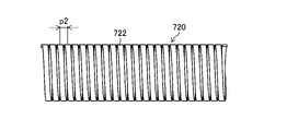
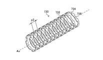
- FIG. 22 to 26 show side views of helical tubes 700, 710, 720, 730 and 740, which are examples of variations of helical tube 640.
- FIG. 22 to 26 show side views of helical tubes 700, 710, 720, 730 and 740, which are examples of variations of helical tube 640.
- the rigidity and flexibility of the helical tube are governed by the material, thickness t, and band width f of the belt-shaped member that constitutes the helical tube.
- the thickness t is about 200 ⁇ m to 300 ⁇ m
- the band width f is about 2 mm to 4 mm
- the initial rigidity and flexibility required for a helical tube can be secured.
- the maximum curvature when the helical tube is curved is governed by the winding pitch (helical pitch) p of the band-shaped member. 22 the second modified helical tube 710 shown in FIG. 23, and the third modified helical tube 720 shown in FIG.
- the helical tube 700 has a longer winding pitch p than the other helical tubes 710 and 720 (p>p1>p2), it can be applied, for example, as a guide tube for a lower gastrointestinal endoscope that requires a large curvature. be.
- the helical tubes 710 and 720 have smaller winding pitches p1 and p2 than the helical tube 700, so that they can be used, for example, as guide tubes for upper gastrointestinal endoscopes that can be used even with a small curvature.
- the strip members 732, 742 of the fourth modified helical tube 730 shown in FIG. 25 and the fifth modified helical tube 740 shown in FIG. and band width f, and each winding pitch p3 is equal.
- the belt-like member 732 of the helical tube 730 has bent portions 734 and 736 that are alternately bent toward the proximal end side and the distal end side of the axis Ax.
- a band-like member 742 of the helical tube 740 has protrusions 744 and 746 that alternately protrude toward the proximal end side and the distal end side of the axis Ax.
- the sheet material and the contact area can be increased.
- the shape retention force of the tube main body in the high-rigidity state (during hardening) can be further enhanced.
- the configuration in which the intermediate layer 614 is arranged between the outer tube 602 and the deformable body 612 has been described as an example, but it is not limited to this.
- a configuration in which an intermediate layer 614 is arranged between an inner tube 604 and a deformable body 612 may be employed, as shown in a longitudinal sectional view of a guide tube 750 of an eighth embodiment shown in FIG.
- FIG. A configuration in which an intermediate layer 614 is arranged in a wide space between 602 and deformable body 612 is preferable.
- the configuration including the shape-variable body 612 (helical tube 640) and the intermediate layer 614 has been described as an example, but the configuration is not limited to this.
- a guide tube having a configuration in which the deformable body 28 having the joint ring member 42 (see FIG. 2) is incorporated into the configuration of the guide tube 600 is also applicable.
- deformable body 28 may be positioned between outer tube 602 and intermediate layer 614, may be positioned between inner tube 604 and deformable body 612, and may be positioned between deformable body 612 and intermediate layer 614. It may be positioned between layers 614 .
- the tube bodies 34, 606 are switched between the flexible state and the high-rigidity state by supplying and discharging air in the internal spaces 36, 608.
- the medical instrument guide device by changing the materials of the joint ring member and the helical tube, it is possible to adjust the hardness of the tube main body in the flexible state (initial state) and high-rigidity state (hardened state).
- the joint ring member and the helical tube are made of polypropylene resin
- the above hardness can be adjusted depending on whether the glass fibers contained in the polypropylene resin are short fibers with a short fiber length or long fibers with a long fiber length. can be adjusted. In this case, the hardness of the former is higher than that of the latter. Since the hardness of the tube main body can be adjusted by changing the material in this way, it is possible to arrange guide tubes having hardness corresponding to the applicable procedure for each applicable procedure.
- the inner diameter of the tube main bodies 34, 606 and the outer diameter of the insertion portion 14 when the insertion portion 14 is inserted into the tube main bodies 34, 606, there is a clearance between the tube main bodies 34, 606 and the insertion portion 14. It is preferably dimensioned to be formed. That is, when the inner diameter of the tube main body 34, 606 is D1 and the outer diameter of the insertion portion 14 is D2, D1 and D2 preferably have a relationship of D1>D2. Further, the above clearance is more preferably 4 mm or less, and even more preferably 1 mm or more and 4 mm or less.
- the inner diameter of the tube main body 34, 606 is preferably 12 mm or less, more preferably 9 mm or more and 12 mm or less. More preferred. Further, when the outer diameter of the insertion portion 14 is, for example, 13 mm, the inner diameter of the tube main body 34, 606 is more preferably 17 mm or less, and even more preferably 14 mm or more and 17 mm or less.
- the clearance By setting the clearance to 4 mm or less in this way, it is possible to prevent body tissue (eg, intestinal wall) from being caught in the gap between the tube main body 34, 606 and the insertion portion 14.
- body tissue eg, intestinal wall
- the body tissue can be prevented from being pinched.
- the clearance by setting the clearance to 1 mm or more, the insertion portion 14 can be moved smoothly relative to the tube main bodies 34 and 606 .
- the effective length of the insertion section 14 refers to the length from the proximal end to the distal end of the insertion section 14 .
- the insertion portion 14 when the total length of the tube main bodies 34 and 606 is, for example, 400 mm, the insertion portion 14 preferably has an effective length of 700 mm or more. Moreover, when the total length of the tube main body 34, 606 is, for example, 700 mm, the insertion portion 14 preferably has an effective length of 1000 mm or more.
- the effective length of the insertion section 14 By making the effective length of the insertion section 14 longer than the total length of the tube main bodies 34 and 606 by 300 mm or more in this manner, the operator can easily insert the tube main bodies 34 and 606 and the insertion section 14 into the body cavity.
- the flexible portion 22 can be reliably gripped and inserted without the 34 and 606 becoming an obstacle.
- the effective length of the insertion portion 14 is 1200 mm as an example.
- the tube bodies 34, 606 with an overall length of 400 mm can be used for large intestine examinations
- the tube bodies 34, 606 with an overall length of 700 mm can be used for large intestine and small intestine examinations.
- FIG. 28 is a perspective view of an endoscope device 800 according to the second embodiment of the invention.
- the guide tube applied to the endoscope device 800 is obtained by attaching a balloon 802 to the guide tube 600 according to the seventh embodiment shown in FIG.
- the endoscope applied to the endoscope apparatus 800 described above has a balloon 804 attached to the insertion portion 14 of the endoscope 12 shown in FIG.
- the balloon 802 described above is an example of the body-fitting portion of the present invention and an example of the tube body balloon of the present invention.
- the balloon 804 described above is an example of the insertion portion balloon of the present invention.
- the guide tube 600 to which the balloon 802 is attached will be described as an example, but the guide tube 10 of the first to sixth embodiments is not limited to this. , 60, 70, 80, 90, 100, and a guide tube in which a balloon 802 is attached to the guide tube 750 of the eighth embodiment.
- FIG. 29 is a cross-sectional view of the essential parts of the guide tube 600 into which the insertion portion 14 is inserted. Since the detailed structure of the guide tube 600 has already been described with reference to FIG. 14, the illustration of the detailed structure of the guide tube 600 is omitted in FIG. 29, and the description thereof is also omitted.
- an inflatable balloon 802 is detachably attached to the tip of the tube body 606 of the guide tube 600 .
- the balloon 802 is made of an elastic material such as rubber, and is composed of a bulging portion 802A in the center and mounting portions 802B, 802B at both ends thereof. Both of the mounting portions 802B, 802B are wound with a thread 806 and fixed to the outer surface of the tube body 606. As shown in FIG.
- an air tube 808 is attached to the outer surface of the tube main body 606 along the axis Ax, and the tip of the air tube 808 is opened in the bulging portion 802A to supply and suck air. It is formed as mouth 810 . Also, the base end of the air tube 808 is connected to a pump 812 arranged outside the tube body 606 .
- This pump 812 is a multi-type air pump capable of supplying (pressurizing) and sucking air. When air is supplied from the pump 812 to the air tube 808, the air is blown out from the air supply suction port 810 to expand the bulging portion 802A. On the other hand, when air is sucked from the pump 812, the air is sucked from the air supply suction port 810 through the air tube 808, and the bulging portion 802A contracts.
- the pump 38 shown in FIG. 14 is connected to the tube main body 606 via the pipe 40, but the pump 812 shown in FIG. 29 can be substituted for the pump 38.
- the pump 812 is connected to the first port 630A of the three-way stopcock 630
- the pipe 40 is connected to the second port 630B
- the air tube 808 is connected to the third port 630C. do.
- the pipe 40 is provided with a valve 634 for opening the internal space 608 (see FIG. 14) to the atmosphere to allow the atmosphere to flow into the internal space 608 .
- the cock 632 of the three-way stopcock 630 When the cock 632 of the three-way stopcock 630 is manually operated to communicate the first port 630A and the second port 630B, the air in the internal space 608 (see FIG. 14) is sucked by the pump 812 switched to the suction side. be able to. As a result, the tube main body 606 changes from a softened state to a hardened state. Also, by opening the valve 634 , the internal space 608 can be opened to the atmosphere, allowing the atmosphere to flow into the internal space 608 . This causes the tube body 606 to change from a cured state to a non-cured state.
- the pump 812 switched to the pressurizing side causes the air supply suction port 810 (see FIG. 29) to flow air. can be blown out. As a result, the bulging portion 802A expands. Further, when the first port 630A and the third port 630C are communicated as described above, air can be sucked from the air supply suction port 810 (see FIG. 29) by the pump 812 switched to the suction side. As a result, the bulging portion 802A contracts.
- the switching operation can be automated instead of the manual switching operation using the three-way stopcock 630.
- the piping 40 and the air tube 808 are connected to the pump 812 via separate electromagnetic valves, and the valve 634 is constructed of an electromagnetic valve.
- the pressure and suction switching timing may be controlled by a controller. This makes it possible to automate the above switching operation.
- an inflatable balloon 804 is detachably attached to the distal end of the insertion section 14 .
- the balloon 804 is made of an elastic material such as rubber, and is composed of a bulging portion 804A in the center and mounting portions 804B, 804B at both ends thereof.
- the mounting portions 804B, 804B are both fixed to the outer surface of the bending portion 20. As shown in FIG.
- an air tube 814 is inserted through the insertion portion 14 along the longitudinal axis G of the insertion portion 14, and the distal end of the air tube 814 is positioned inside the bulging portion 804A. It is formed as an air supply suction port 816 which is opened in the outer surface of the part 20 . Also, the proximal end of the air tube 814 is connected to a pump (not shown) arranged outside the insertion portion 14 . Therefore, when air is supplied from the pump to the air tube 814, the air is blown out from the air supply suction port 816 to expand the bulging portion 804A.
- the pump 812 for the balloon 802 as the pump for the balloon 804 .
- the air tube 814 is connected to the pump 812 via an electromagnetic valve or the like, air can be supplied to and sucked from the balloon 804 .
- the pump 812 for the balloon 802 as the pump for the balloon 804 in this way, the initial cost and running cost of the endoscope apparatus 800 can be reduced.
- FIG. XXXIA of FIG. 31 to XXXIIH of FIG. 32 show an example of a procedure in chronological order when the endoscope device 800 is applied as a device for a small intestine.
- reference character Q indicates the stomach, R the pylorus, S the duodenum, U the small intestine, and Z the lesion.
- the insertion portion 14 is inserted into the body while the insertion portion 14 is inserted into the tube main body 606 and the balloon 804 is deflated. That is, the distal end portion of the insertion portion 14 is inserted into the stomach Q from the mouth of the subject through the esophagus.
- XXXIA in FIG. 31 shows a state in which the distal end of the insertion portion 14 is inserted into the stomach Q.
- XXXIB of FIG. 31 shows a state in which the distal ends of the insertion portion 14 and the tube main body 606 are inserted into the stomach Q.
- XXXIC of FIG. 31 shows a state in which the insertion section 14 is inserted along the curved shape of the duodenum S and the distal end of the insertion section 14 is inserted into the ascending portion of the duodenum S.
- XXXID in FIG. 31 shows a state in which the balloon 804 is in close contact with the ascending portion of the duodenum S and the insertion section 14 is fixed to the duodenum S.
- FIG. 31 shows a state in which the balloon 804 is in close contact with the ascending portion of the duodenum S and the insertion section 14 is fixed to the duodenum S.
- XXXIE of FIG. 31 shows a state in which the tube body 606 is inserted along the curved shape of the duodenum S, and the tip of the tube body 606 is inserted up to the front of the balloon 804 of the insertion section 14.
- the tube main body 606 is changed from the uncured state to the cured state. That is, the tube body 606 is hardened by sucking the air in the internal space 608 (see FIG. 14) of the tube body 606 with the pump 812 (see FIG. 30).
- XXXIE of FIG. 31 shows a state in which the tube body 606 has been hardened into a shape that conforms to the curved shape of the duodenum S.
- XXXIF of FIG. 31 shows a state in which the balloon 802 is in close contact with the ascending portion of the duodenum S and the tube body 606 is fixed to the duodenum S.
- FIG. 31 shows a state in which the balloon 804 is deflated to release the insertion portion 14 from the duodenum S.
- XXXIH of FIG. 31 shows a state in which the distal end portion of the insertion portion 14 is inserted deep into the small intestine U along the curved shape of the small intestine U.
- FIG. When the insertion portion 14 is advanced, the tube main body 606 is hardened into a shape that follows the curved shape of the duodenum S, so that the distal end portion of the insertion portion 14 can be stably advanced toward the deep portion of the small intestine U. can.
- XXXIIA of FIG. 32 shows a state in which the balloon 804 is in close contact with the small intestine U and the insertion portion 14 is fixed to the small intestine U.
- FIG. 32 shows a state in which the balloon 804 is in close contact with the small intestine U and the insertion portion 14 is fixed to the small intestine U.
- FIG. 32 shows a state in which the balloon 802 is deflated to release the fixation of the tube body 606 to the duodenum S.
- the tube main body 606 is changed from the cured state to the non-cured state. That is, the inner space 608 (see FIG. 14) of the tube main body 606 is opened to the atmosphere and the air flows into the inner space 608 to soften the tube main body 606 .
- XXXIIC of FIG. 32 shows a state in which the tube body 606 is inserted along the curved shape of the small intestine U, and the tip of the tube body 606 is inserted up to the front of the balloon 804 of the insertion section 14.
- XXXID of FIG. 32 shows a state in which the balloon 802 is in close contact with the small intestine U and the tube main body 606 is fixed to the small intestine U.
- FIG. 32 shows a state in which the balloon 802 is in close contact with the small intestine U and the tube main body 606 is fixed to the small intestine U.
- XXXIIE to XXXIIF in FIG. 32 shows a state in which the small intestine U is pulled toward the stomach Q side while the balloons 802 and 804 are in close contact with the small intestine U.
- FIG. This procedure contracts the small intestine U in the longitudinal direction, so that the lesion Z of the small intestine U can be brought closer to the distal end of the insertion section 14 .
- the tube main body 606 is changed from the uncured state to the cured state. That is, the tube body 606 is hardened by sucking the air in the internal space 608 (see FIG. 14) of the tube body 606 with the pump 812 (see FIG. 30).
- XXXIF of FIG. 32 shows a state in which the tube body 606 has been hardened into a shape that conforms to the curved shape of the contracted small intestine U.
- FIG. 32 shows a state in which the balloon 804 is deflated to release the insertion portion 14 from the small intestine U.
- XXXIIH of FIG. 32 shows a state in which the distal end portion of the insertion portion 14 is inserted along the curved shape of the small intestine U to the vicinity of the lesion Z.
- XXXIIH in FIG. 32 shows a state in which the distal end portion of the insertion portion 14 is inserted along the curved shape of the small intestine U to the vicinity of the lesion Z.
- the tube main body 606 is hardened into a shape that conforms to the curved shape of the small intestine U, so the distal end portion of the insertion section 14 can be stably advanced toward the lesion Z. .
- the balloon 804 is inflated and brought into close contact with the small intestine U, thereby fixing the distal end of the insertion section 14 to the small intestine U.
- a treatment tool (not shown) is inserted from the proximal end side of the insertion section 14, and the treatment tool is led out from a treatment tool lead-out port (not shown) at the distal end side of the insertion section 14 to treat the lesion Z.
- the tube main body 606 is fixed to the small intestine U by the balloon 802, and the distal end of the insertion section 14 is fixed to the small intestine U by the balloon 804. (Distal hard portion 18) can be positioned at an appropriate treatment position. As a result, the lesion 506 can be appropriately treated.
- the balloon 804 of the insertion section 14 is contracted to release the insertion section 14 from the small intestine U.
- the tube main body 606 is changed from the hardened state to the non-hardened state, and the balloon 802 is deflated to release the fixation of the tube main body 606 to the small intestine U.
- the step of inflating and deflating the balloon 804 (first inflation) is performed. contraction step), a step of inflating and contracting the balloon 802 (second expansion/contraction step), a step of changing the tube body 606 between a non-hardened state and a hardened state (hardness varying step), and an insertion portion 14 and the tube main body 606 (advancement/retraction step) are selectively executed to move the distal end portion of the insertion portion 14 toward the lesion Z existing deep in the small intestine U stably. can move forward. In addition, it is possible to accurately treat the lesion Z with the treatment instrument.
- the balloon 804 is provided on the endoscope 12 side, but the present invention is not limited to this. may be provided.
- the operation method of the endoscope device in this configuration (that is, the configuration in which the balloon 802 is provided only on the guide tube 600 side) is basically the same as the operation method shown in FIGS.
- the insertion section 14 can be fixed to the intestinal tract by bending the bending section 20 and hooking the distal end (hard distal end section 18) on the intestinal tract or the like. .
- FIG. 33 is a cross-sectional view showing the essential parts of the balloon 820 of the first modified example.
- the balloon 820 is made of an elastic material such as rubber, and is composed of two swelling portions 820A and 820B and mounting portions 820C and 820C.
- the attachment portions 820C, 820C By fixing the attachment portions 820C, 820C to the outer surface of the tube main body 606, the bulging portion 820A is attached to the distal end side of the tube main body 606, and the bulging portion 820B is attached to the proximal end side of the tube main body 606.
- an air tube 822 is attached to the outer surface of the tube main body 606 along the axis Ax, and the tip of the air tube 822 is opened in the bulging portion 820B to supply and suck air. It is formed as mouth 824 . Also, the base end of the air tube 822 is connected to a pump (not shown) arranged outside the tube main body 606 . When air is supplied from this pump to the air tube 822, the air is blown out from the air supply suction port 824 to expand the bulging portions 820A and 820B.
- the balloon 820 having such two bulging portions 820A and 820B can be applied as a tube body balloon.
- FIG. 34 is a cross-sectional view showing the essential parts of the balloon 830 of the second modified example.
- the balloon 830 is composed of a central bulging portion 830A and mounting portions 830B and 830B at both ends thereof. Portion 830B is secured to the outer surface of tube body 606 . According to this balloon 830 , when the bulging portion 830 A is inflated, this bulging portion 830 A can expand both radially outward and radially inward of the tube body 606 . As a result, the inflated bulging portion 830A can be in close contact with both the intestinal wall (not shown) and the insertion portion 14 .
- an air tube 832 is attached to the outer surface of the tube main body 606 along the axis Ax, and the tip of the air tube 832 is opened in the bulging portion 830A to supply and suck air. It is formed as mouth 834 . Also, the base end of the air tube 832 is connected to a pump (not shown) arranged outside the tube main body 606 . When air is supplied from this pump to the air tube 832, the air is blown out from the air supply suction port 834, and the swelling portion 830A is expanded.
- the bulging portion 830A since a part of the bulging portion 830A is in close contact with the insertion portion 14, it is possible to prevent body tissue (eg, intestinal wall) from being caught in the gap between the tube main body 606 and the insertion portion 14. .
- body tissue eg, intestinal wall
- the air is sucked from the air supply suction port 834 through the air tube 832, and the bulging portion 830A is contracted. Even the balloon 830 having such a bulging portion 830A can be applied as a tube body balloon.
- FIG. 35 is a cross-sectional view showing the essential parts of the balloon 840 of the third modified example.
- the tube body 606 in this example has a barrel 842 that accommodates the tube body 606 therein.
- a space 844 between the tube main body 606 and the cylindrical body 842 is formed as a sealed space, and this space 844 is configured as an air passage and connected to a pump (not shown).
- the balloon 840 is attached to the distal end portion of the cylindrical body 842 , and an air supply/suction port 846 is formed at the distal end portion of the cylindrical body 842 positioned within the bulging portion 840 A of the balloon 840 .
- the balloon 840 is attached to the tube main body 606 by fixing the mounting portions 840B, 840B at both ends of the bulging portion 840A to the outer surface of the tubular body 842. As shown in FIG.
- the balloon 840 shown in FIG. 35 when air is supplied from the pump to the space 844, the air is blown out from the air supply suction port 846, and the bulging portion 840A is inflated. On the other hand, when air is sucked from the pump, the air is sucked from the air supply suction port 846 through the space 844, and the bulging portion 840A contracts. Even the balloon 840 attached to the distal end portion of the tubular body 842 in this way can be applied as a tube body balloon.
- FIG. 36 is a cross-sectional view showing the essential parts of a balloon 850 of the fourth modified example.
- the tube body 606 in this example has a barrel 852 that accommodates the tube body 606 therein.
- a space 854 between the tube main body 606 and the cylindrical body 852 is formed as a sealed space, and this space 854 is configured as an air passage and connected to a pump (not shown).
- the cylindrical body 852 has a distal end made of an elastic material such as rubber, and the distal end is formed as a bulging portion 850A of the balloon 850 .
- a portion of the cylindrical body 852 excluding the tip portion that functions as the bulging portion 850A is made of a material that cannot be expanded or contracted (for example, hard plastic).
- the balloon 850 shown in FIG. 36 when air is supplied from the pump to the space 854, the tip of the cylinder 852 indicated by the two-dot chain line in FIG. to inflate.
- the tip of the cylinder 852 indicated by the two-dot chain line in FIG. to inflate.
- the air when air is sucked from the pump, the air is sucked through the space 854, and the bulging portion 850A contracts as indicated by the chain double-dashed line in FIG.
- Even the balloon 850 in which the bulging portion 850A is formed in the tubular body 852 in this manner can be applied as a tube body balloon.
- FIG. 37 is a cross-sectional view showing the essential parts of the balloon 860 of the fifth modified example.
- the tube body 606 in this example has a barrel 862 that accommodates the tube body 606 therein.
- a thin portion that functions as a bulging portion 860A of the balloon 860 is formed at the distal end portion of the tubular body 862 .
- a closed space 866 is formed between the bulging portion 860A and the tube main body 606 .
- the tubular body 860 is formed with a multi-lumen tube 864 along the axis Ax.
- the distal end of this multi-lumen tube 864 opens into a sealed space 866 and is formed as an air suction port 868 .
- the proximal end of the multi-lumen tube 864 is connected to a pump (not shown).
- the balloon 860 shown in FIG. 37 when air is supplied from the pump to the multi-lumen tube 864, the air is ejected from the air supply suction port 868 into the sealed space 866, and the bulging portion 860A is formed as shown by the solid line in FIG. Inflate.
- the air when air is sucked from the pump, the air is sucked from the air supply suction port 868 through the multi-lumen tube 864, and the bulging portion 860A contracts as indicated by the chain double-dashed line in FIG.
- Even the balloon 860 in which the cylindrical body 862 is formed with the thin bulging portion 860A can be used as a tube body balloon.
- the balloon 870 has four bulging portions 870A, 870B, 870C, 870D along the outer peripheral surface of the tube body 606 at the distal end of the tube body 606.
- the balloon 870 is configured such that these bulging portions 870A, 870B, 870C, and 870D can be independently expanded and contracted.
- the swelling portions 870A, 870B, 870C, and 870D are inflated and these swelling portions 870A, 870B, 870C, and 870D are brought into close contact with the intestinal wall (not shown), thereby It is possible to fix the tip of the body 606 to the intestinal wall. Also, by inflating at least one of the bulging portions 870A, 870B, 870C, and 870D and bringing this bulging portion into close contact with the intestinal wall (not shown), the direction of the distal end of the tube main body 606 can be changed. can be adjusted. Specifically, for example, if only the bulging portion 870A located on the upper side in FIG.
- the distal end portion of the tube main body 606 can be tilted downward in FIG. . That is, by inflating at least one of the swelling portions 870A, 870B, 870C, and 870D, the distal end portion of the tube main body 606 can be tilted in four directions of up, down, left, and right in FIG. Even the balloon 870 having such bulging portions 870A, 870B, 870C, and 870D can be applied as a tube body balloon.
- the balloon 870 having four bulging portions 870A, 870B, 870C, and 870D was described as an example of a balloon capable of changing the direction of the distal end portion of the tube main body 606, but the present invention is limited to this. not to be That is, any balloon having at least one or more of the bulging portions 870A, 870B, 870C, and 870D can be applied.
- the balloons 802, 820, 830, 840, 850, 860, and 870 are described as examples of the body-adhering portion that makes the distal end portion of the tube body 606 adhere to the body.
- Another embodiment of the body fitting portion will be described with reference to FIG.
- FIG. 39 is a perspective view of a main part of a tube main body 606 to which another embodiment of the body-fitting portion is applied.
- FIG. 40 is a cross-sectional view of main parts of the tube main body 606 shown in FIG.
- the tube main body 606 of this example has a tubular body 880 that accommodates the tube main body 606 therein. is provided with an intracorporeal contact portion 882 of this example.
- a thin portion 884 is formed at the tip of the cylinder 880 .
- the thin portion 884 is formed along the circumferential direction of the cylindrical body 880, and the thin portion 884 is formed with a suction port 892, which will be described later.
- the thin portion 884 has a diameter smaller than the outer diameter of the tubular body 880 and larger than the inner diameter of the tubular body 880, and a sealed space 886 is formed between the thin portion 884 and the tube main body 606.
- the tubular body 880 is formed with a multi-lumen tube 888 along the axis Ax.
- the tip of this multi-lumen tube 888 is opened to the sealed space 886 and formed as an air suction port 890 .
- the proximal end of the multi-lumen tube 888 is connected to a suction pump (not shown).
- the body-fitting portion 882 of this example is configured to have a suction port 892 arranged at the distal end portion of the tube main body 606 .
- the body contact part 882 has a soft sponge member 894 that covers the suction port 892 .
- the sponge member 894 is configured in a tubular shape, and is attached to the distal end portion of the tubular body 880 which is recessed by forming the thin portion 884 .
- the body-fitting portion 882 configured as described above, when air is sucked from the suction pump, the intestinal air is sucked into the multi-lumen tube 888 through the plurality of suction ports 892 through the closed space 866 .
- the tip of the tube body 606 is brought into close contact with the intestinal wall (not shown) via the cylindrical body 880 (sponge member 894).
- the distal end of the tube main body 606 is fixed inside the body.
- the body-adhering portion 882 having the suction port 892 the distal end portion of the tube main body 606 can be brought into close contact with the body.
- the body-contacting portion 882 of the embodiment has a sponge member 894 , the intestinal wall is adsorbed to the suction port 892 via the sponge member 894 .
- the intestinal wall can be protected from the periphery (edge) of the suction port 892 as compared with the case where the intestinal wall is directly adsorbed to the suction port 892 .
- the sponge member 894 is not an essential member, it is preferable to provide it from the viewpoint of protecting the intestinal wall as described above.
- the sponge member 894 is an example of the porous entanglement prevention member of the present invention. good too.
- the sponge member 904 functions as a cushioning material for the intestinal wall, so it can be applied more preferably than a hard porous member.
- an endoscope having an insertion section is applied as a medical device guided by the medical device guide device of the present invention, but the present invention is not limited to this, for example, It can also be applied to medical treatment instruments such as manipulators.
Abstract
Priority Applications (4)
| Application Number | Priority Date | Filing Date | Title |
|---|---|---|---|
| EP22759241.7A EP4298985A1 (fr) | 2021-02-25 | 2022-01-28 | Dispositif de guidage d'instrument médical et dispositif d'endoscope |
| JP2023502211A JPWO2022181200A1 (fr) | 2021-02-25 | 2022-01-28 | |
| CN202280015877.0A CN116867418A (zh) | 2021-02-25 | 2022-01-28 | 医疗器具用引导装置及内窥镜装置 |
| US18/452,551 US20230389783A1 (en) | 2021-02-25 | 2023-08-20 | Medical instrument guide device and endoscope apparatus |
Applications Claiming Priority (4)
| Application Number | Priority Date | Filing Date | Title |
|---|---|---|---|
| JP2021-028421 | 2021-02-25 | ||
| JP2021028421 | 2021-02-25 | ||
| JP2021-176105 | 2021-10-28 | ||
| JP2021176105 | 2021-10-28 |
Related Child Applications (1)
| Application Number | Title | Priority Date | Filing Date |
|---|---|---|---|
| US18/452,551 Continuation US20230389783A1 (en) | 2021-02-25 | 2023-08-20 | Medical instrument guide device and endoscope apparatus |
Publications (1)
| Publication Number | Publication Date |
|---|---|
| WO2022181200A1 true WO2022181200A1 (fr) | 2022-09-01 |
Family
ID=83049224
Family Applications (1)
| Application Number | Title | Priority Date | Filing Date |
|---|---|---|---|
| PCT/JP2022/003292 WO2022181200A1 (fr) | 2021-02-25 | 2022-01-28 | Dispositif de guidage d'instrument médical et dispositif d'endoscope |
Country Status (4)
| Country | Link |
|---|---|
| US (1) | US20230389783A1 (fr) |
| EP (1) | EP4298985A1 (fr) |
| JP (1) | JPWO2022181200A1 (fr) |
| WO (1) | WO2022181200A1 (fr) |
Citations (8)
| Publication number | Priority date | Publication date | Assignee | Title |
|---|---|---|---|---|
| JP2003501197A (ja) * | 1999-06-11 | 2003-01-14 | サイムド ライフ システムズ, インコーポレイテッド | 医療デバイス用の可撓性の大きな中間部を備えたシース |
| JP2009082455A (ja) * | 2007-09-28 | 2009-04-23 | Ai Matsuo | 手術用吸引管 |
| JP2011194126A (ja) | 2010-03-23 | 2011-10-06 | Fujifilm Corp | 内視鏡若しくは処置具のガイド管 |
| JP2012024597A (ja) * | 2011-09-15 | 2012-02-09 | Olympus Medical Systems Corp | 内視鏡用処置具 |
| JP3204367U (ja) * | 2016-02-04 | 2016-06-02 | リブト株式会社 | 内視鏡用感染防止シース |
| WO2016185842A1 (fr) * | 2015-05-18 | 2016-11-24 | オリンパス株式会社 | Tube flexible, dispositif insérable et endoscope les utilisant |
| WO2020017534A1 (fr) * | 2018-07-17 | 2020-01-23 | 富士フイルム株式会社 | Composition de tube d'aide à l'insertion, tube d'aide à l'insertion, ensemble tube d'aide à l'insertion/endoscope, dispositif d'endoscope et procédé de production de tube d'aide à l'insertion |
| US20200275983A1 (en) * | 2008-02-05 | 2020-09-03 | Steerable Instruments nv | Steerable tube |
-
2022
- 2022-01-28 JP JP2023502211A patent/JPWO2022181200A1/ja active Pending
- 2022-01-28 EP EP22759241.7A patent/EP4298985A1/fr active Pending
- 2022-01-28 WO PCT/JP2022/003292 patent/WO2022181200A1/fr active Application Filing
-
2023
- 2023-08-20 US US18/452,551 patent/US20230389783A1/en active Pending
Patent Citations (8)
| Publication number | Priority date | Publication date | Assignee | Title |
|---|---|---|---|---|
| JP2003501197A (ja) * | 1999-06-11 | 2003-01-14 | サイムド ライフ システムズ, インコーポレイテッド | 医療デバイス用の可撓性の大きな中間部を備えたシース |
| JP2009082455A (ja) * | 2007-09-28 | 2009-04-23 | Ai Matsuo | 手術用吸引管 |
| US20200275983A1 (en) * | 2008-02-05 | 2020-09-03 | Steerable Instruments nv | Steerable tube |
| JP2011194126A (ja) | 2010-03-23 | 2011-10-06 | Fujifilm Corp | 内視鏡若しくは処置具のガイド管 |
| JP2012024597A (ja) * | 2011-09-15 | 2012-02-09 | Olympus Medical Systems Corp | 内視鏡用処置具 |
| WO2016185842A1 (fr) * | 2015-05-18 | 2016-11-24 | オリンパス株式会社 | Tube flexible, dispositif insérable et endoscope les utilisant |
| JP3204367U (ja) * | 2016-02-04 | 2016-06-02 | リブト株式会社 | 内視鏡用感染防止シース |
| WO2020017534A1 (fr) * | 2018-07-17 | 2020-01-23 | 富士フイルム株式会社 | Composition de tube d'aide à l'insertion, tube d'aide à l'insertion, ensemble tube d'aide à l'insertion/endoscope, dispositif d'endoscope et procédé de production de tube d'aide à l'insertion |
Also Published As
| Publication number | Publication date |
|---|---|
| EP4298985A1 (fr) | 2024-01-03 |
| US20230389783A1 (en) | 2023-12-07 |
| JPWO2022181200A1 (fr) | 2022-09-01 |
Similar Documents
| Publication | Publication Date | Title |
|---|---|---|
| EP1487516B1 (fr) | Element gonflable pour gaine d'endoscope | |
| JP6368256B2 (ja) | 内視鏡システム | |
| JP4738593B2 (ja) | 内視鏡の固定及び位置決め装置 | |
| US10426925B2 (en) | Medical devices for the identification and treatment of bodily passages | |
| US6793661B2 (en) | Endoscopic sheath assemblies having longitudinal expansion inhibiting mechanisms | |
| EP2278908B1 (fr) | Dispositif de navigation biologique | |
| US9333322B2 (en) | Adjustable variable stiffness medical device and methods of use | |
| JP6444809B2 (ja) | 内視鏡システム | |
| US20070088319A1 (en) | Braided minimally invasive channel | |
| JP6253796B2 (ja) | 結腸内視鏡と追加管との間を結合するための装置および方法 | |
| US9498224B2 (en) | Ligation band dispensing cap assembly and methods of use | |
| JP5378092B2 (ja) | バルーンカテーテル及びシースの加工方法 | |
| WO2022181200A1 (fr) | Dispositif de guidage d'instrument médical et dispositif d'endoscope | |
| CN116867418A (zh) | 医疗器具用引导装置及内窥镜装置 | |
| JP2010110444A (ja) | 内視鏡の可撓管 | |
| KR101497359B1 (ko) | 내시경 디바이스 | |
| JP7306376B2 (ja) | 結石除去用バルーンカテーテル | |
| AU2016427268B2 (en) | Disposable sheath device | |
| JP6756780B2 (ja) | 内視鏡システム | |
| WO2021059943A1 (fr) | Cathéter à ballonnet | |
| WO2021130851A1 (fr) | Sur-tube médical |
Legal Events
| Date | Code | Title | Description |
|---|---|---|---|
| 121 | Ep: the epo has been informed by wipo that ep was designated in this application |
Ref document number: 22759241 Country of ref document: EP Kind code of ref document: A1 |
|
| WWE | Wipo information: entry into national phase |
Ref document number: 202280015877.0 Country of ref document: CN Ref document number: 2023502211 Country of ref document: JP |
|
| WWE | Wipo information: entry into national phase |
Ref document number: 2022759241 Country of ref document: EP |
|
| NENP | Non-entry into the national phase |
Ref country code: DE |
|
| ENP | Entry into the national phase |
Ref document number: 2022759241 Country of ref document: EP Effective date: 20230925 |