WO2022181061A1 - 推定モデル生成装置および加工状態推定装置 - Google Patents
推定モデル生成装置および加工状態推定装置 Download PDFInfo
- Publication number
- WO2022181061A1 WO2022181061A1 PCT/JP2022/000133 JP2022000133W WO2022181061A1 WO 2022181061 A1 WO2022181061 A1 WO 2022181061A1 JP 2022000133 W JP2022000133 W JP 2022000133W WO 2022181061 A1 WO2022181061 A1 WO 2022181061A1
- Authority
- WO
- WIPO (PCT)
- Prior art keywords
- waveform
- estimation model
- estimation
- data
- processing
- Prior art date
- Legal status (The legal status is an assumption and is not a legal conclusion. Google has not performed a legal analysis and makes no representation as to the accuracy of the status listed.)
- Ceased
Links
Images




Classifications
-
- B—PERFORMING OPERATIONS; TRANSPORTING
- B23—MACHINE TOOLS; METAL-WORKING NOT OTHERWISE PROVIDED FOR
- B23K—SOLDERING OR UNSOLDERING; WELDING; CLADDING OR PLATING BY SOLDERING OR WELDING; CUTTING BY APPLYING HEAT LOCALLY, e.g. FLAME CUTTING; WORKING BY LASER BEAM
- B23K26/00—Working by laser beam, e.g. welding, cutting or boring
- B23K26/02—Positioning or observing the workpiece, e.g. with respect to the point of impact; Aligning, aiming or focusing the laser beam
- B23K26/03—Observing, e.g. monitoring, the workpiece
- B23K26/032—Observing, e.g. monitoring, the workpiece using optical means
-
- B—PERFORMING OPERATIONS; TRANSPORTING
- B23—MACHINE TOOLS; METAL-WORKING NOT OTHERWISE PROVIDED FOR
- B23K—SOLDERING OR UNSOLDERING; WELDING; CLADDING OR PLATING BY SOLDERING OR WELDING; CUTTING BY APPLYING HEAT LOCALLY, e.g. FLAME CUTTING; WORKING BY LASER BEAM
- B23K31/00—Processes relevant to this subclass, specially adapted for particular articles or purposes, but not covered by any single one of main groups B23K1/00 - B23K28/00
-
- B—PERFORMING OPERATIONS; TRANSPORTING
- B23—MACHINE TOOLS; METAL-WORKING NOT OTHERWISE PROVIDED FOR
- B23K—SOLDERING OR UNSOLDERING; WELDING; CLADDING OR PLATING BY SOLDERING OR WELDING; CUTTING BY APPLYING HEAT LOCALLY, e.g. FLAME CUTTING; WORKING BY LASER BEAM
- B23K26/00—Working by laser beam, e.g. welding, cutting or boring
-
- B—PERFORMING OPERATIONS; TRANSPORTING
- B23—MACHINE TOOLS; METAL-WORKING NOT OTHERWISE PROVIDED FOR
- B23K—SOLDERING OR UNSOLDERING; WELDING; CLADDING OR PLATING BY SOLDERING OR WELDING; CUTTING BY APPLYING HEAT LOCALLY, e.g. FLAME CUTTING; WORKING BY LASER BEAM
- B23K26/00—Working by laser beam, e.g. welding, cutting or boring
- B23K26/02—Positioning or observing the workpiece, e.g. with respect to the point of impact; Aligning, aiming or focusing the laser beam
- B23K26/03—Observing, e.g. monitoring, the workpiece
-
- B—PERFORMING OPERATIONS; TRANSPORTING
- B23—MACHINE TOOLS; METAL-WORKING NOT OTHERWISE PROVIDED FOR
- B23K—SOLDERING OR UNSOLDERING; WELDING; CLADDING OR PLATING BY SOLDERING OR WELDING; CUTTING BY APPLYING HEAT LOCALLY, e.g. FLAME CUTTING; WORKING BY LASER BEAM
- B23K26/00—Working by laser beam, e.g. welding, cutting or boring
- B23K26/20—Bonding
- B23K26/21—Bonding by welding
-
- B—PERFORMING OPERATIONS; TRANSPORTING
- B23—MACHINE TOOLS; METAL-WORKING NOT OTHERWISE PROVIDED FOR
- B23K—SOLDERING OR UNSOLDERING; WELDING; CLADDING OR PLATING BY SOLDERING OR WELDING; CUTTING BY APPLYING HEAT LOCALLY, e.g. FLAME CUTTING; WORKING BY LASER BEAM
- B23K31/00—Processes relevant to this subclass, specially adapted for particular articles or purposes, but not covered by any single one of main groups B23K1/00 - B23K28/00
- B23K31/006—Processes relevant to this subclass, specially adapted for particular articles or purposes, but not covered by any single one of main groups B23K1/00 - B23K28/00 relating to using of neural networks
-
- B—PERFORMING OPERATIONS; TRANSPORTING
- B23—MACHINE TOOLS; METAL-WORKING NOT OTHERWISE PROVIDED FOR
- B23K—SOLDERING OR UNSOLDERING; WELDING; CLADDING OR PLATING BY SOLDERING OR WELDING; CUTTING BY APPLYING HEAT LOCALLY, e.g. FLAME CUTTING; WORKING BY LASER BEAM
- B23K31/00—Processes relevant to this subclass, specially adapted for particular articles or purposes, but not covered by any single one of main groups B23K1/00 - B23K28/00
- B23K31/12—Processes relevant to this subclass, specially adapted for particular articles or purposes, but not covered by any single one of main groups B23K1/00 - B23K28/00 relating to investigating the properties, e.g. the weldability, of materials
- B23K31/125—Weld quality monitoring
Definitions
- the present disclosure relates to a laser processing state estimation model generation method and a processing state estimation device.
- a known method is to detect visible light, reflected light, or thermal radiation emitted from a workpiece during laser processing when determining the state of processing in laser processing.
- the welding state determination device described in Patent Document 1 detects the intensity of plasma light and reflected light emitted from a workpiece during laser welding, and extracts the peak of the feature value based on the intensity of the detected light in a predetermined section. Use the values to determine the state of the workpiece.
- An estimation model generation device includes: A device for generating an estimation model for estimating a processing state of laser processing, During laser processing by the first apparatus, first thermal radiation, first visible light, first reflected light, and first laser light are observed from the workpiece, An information acquisition unit that acquires first waveform data including a first waveform and a second waveform for at least two of the first thermal radiation, the first visible light, the first reflected light, and the first laser beam.
- An information acquisition unit that acquires first waveform data including a first waveform and a second waveform for at least two of the first thermal radiation, the first visible light, the first reflected light, and the first laser beam.
- An estimation model generation device includes: A device for generating an estimation model for estimating a processing state of laser processing in the first device and the second device, During laser processing by the first device, third thermal radiation, third visible light, third reflected light, and third laser light are observed from the workpiece, During laser processing by the second device, fourth thermal radiation, fourth visible light, fourth reflected light, and fourth laser light are observed from the workpiece, third waveform data including fifth and sixth waveforms for at least two of the third thermal radiation, the third visible light, the third reflected light, and the third laser light; the fourth thermal radiation; the fourth visible light; an information acquisition unit that acquires fourth waveform data including a seventh waveform and an eighth waveform for at least two of the light, the fourth reflected light, and the fourth laser light; Multiplying the fifth waveform by a third coefficient calculated from the relationship between the fifth waveform and the seventh waveform, and multiplying the sixth waveform by a fourth coefficient calculated from the relationship between the sixth waveform and the eighth waveform , an
- FIG. 1 is a block diagram showing an estimation model generation device according to a first embodiment
- FIG. 1 is a block diagram showing a machining state estimating device according to a first embodiment
- Block diagram showing the first device Block diagram showing the second device Graph showing the first waveform data acquired by the information acquisition unit Graph showing second waveform data acquired by the information acquisition unit Graph of normalized first waveform data Graph of normalized first transformation data Graph showing the relationship between the average signal intensity and the defocus amount in the first waveform data and the first conversion data Graph showing the relationship between the correct value and the estimated value when the first converted data and the second waveform data are used as input data when estimating the machining state based on the first estimation model in the machining state estimating device.
- Block diagram showing an estimation model generation device according to a second embodiment Block diagram showing a machining state estimating device according to a second embodiment
- a sensor When monitoring the processing state during laser processing, a sensor detects thermal radiation, reflected light, visible light, and laser light emitted from the laser processing portion, like the welding state determination device described in Patent Document 1.
- an estimation model is generated, and the sensing data at the time of processing is processed using the estimation model.
- Methods for determining status are also known.
- an estimation model may be created by acquiring sensing data for learning, for example, using an experimental apparatus. For the reason described above, it is difficult to use the estimation model created in this way for estimating the machining state of the equipment used in the production line.
- the present inventors have studied a method that allows an estimation model generated using sensing data from a given processing device to be used by other processing devices, and have arrived at the following invention.
- the present disclosure provides an estimated model generating device and a machining state estimating device that allow an estimated model generated by a given processing device to be used by another processing device.
- An estimation model generation device includes: A device for generating an estimation model for estimating a processing state of laser processing, During laser processing by the first apparatus, first thermal radiation, first visible light, first reflected light, and first laser light are observed from the workpiece, An information acquisition unit that acquires first waveform data including a first waveform and a second waveform for at least two of the first thermal radiation, the first visible light, the first reflected light, and the first laser beam.
- An information acquisition unit that acquires first waveform data including a first waveform and a second waveform for at least two of the first thermal radiation, the first visible light, the first reflected light, and the first laser beam.
- a machining state estimation device includes: A device for estimating a processing state of laser processing in a second device different from the first device, During laser processing by the second device, a second thermal radiation, a second visible light, a second reflected light, and a second laser beam are observed from the workpiece, An information acquisition unit that acquires second waveform data including a third waveform and a fourth waveform for at least two of the second thermal radiation, the second visible light, the second reflected light, and the second laser beam. When, The third waveform is multiplied by a first coefficient calculated from the relationship between the third waveform and the first waveform, and the second coefficient calculated from the relationship between the fourth waveform and the second waveform is multiplied by the second coefficient. an information conversion unit that multiplies the four waveforms to generate first conversion data; a storage unit that stores the first estimation model generated by the estimation model generation device; an estimation unit that estimates the machining state from the first conversion data based on the first estimation model; Prepare.
- an estimated model generating device and a machining state estimating device that can use an estimated model generated by a predetermined processing device in another processing device.
- An estimated model generating device generates a first estimated model using the first waveform data from the first device.
- the waveform data in the second device is converted to conform to the waveform data in the first device, so that the same first estimation model is used in different devices. can be used.
- the first coefficient and the second coefficient may be determined such that the first conversion data is generated while maintaining the ratio of the average values of the first waveform and the second waveform.
- An estimation model generation device includes: A device for generating an estimation model for estimating a processing state of laser processing in the first device and the second device, During laser processing by the first device, third thermal radiation, third visible light, third reflected light, and third laser light are observed from the workpiece, During laser processing by the second device, fourth thermal radiation, fourth visible light, fourth reflected light, and fourth laser light are observed from the workpiece, third waveform data including fifth and sixth waveforms for at least two of the third thermal radiation, the third visible light, the third reflected light, and the third laser light; and the fourth thermal radiation.
- an information acquisition unit configured to acquire fourth waveform data including a seventh waveform and an eighth waveform for at least two of radiation, the fourth visible light, the fourth reflected light, and the fourth laser light;
- the fifth waveform is multiplied by a third coefficient calculated from the relationship between the fifth waveform and the seventh waveform, and the fourth coefficient calculated from the relationship between the sixth waveform and the eighth waveform is multiplied by the fourth coefficient.
- an information conversion unit that multiplies the six waveforms to generate second conversion data
- an estimation model generation unit that generates a second estimation model for estimating the machining state by the first device and a third estimation model for estimating the machining state by the second device
- a storage unit that stores the second estimation model and the third estimation model
- the estimated model generation unit Generating the second estimation model by performing machine learning using teacher data in which the third waveform data is used as an explanatory variable and the processed state is used as an objective variable
- the third estimation model is generated by performing machine learning using teacher data in which the second converted data is used as an explanatory variable and the processing state is used as an objective variable.
- the third estimation model for the second device is generated while using the waveform data in the first device. can do.
- the third coefficient and the fourth coefficient may be determined such that the second conversion data is generated while maintaining the ratio of the average values of the seventh waveform and the eighth waveform.
- a machining state estimation device includes: A device for estimating the processing state of laser processing, a storage unit that stores a third estimation model generated by the estimation model generation device according to claim 4 or 5; an information acquisition unit that acquires the fourth waveform data; an estimation unit that estimates the machining state from the fourth waveform data based on the third estimation model; Prepare.
- an estimated model can be generated for each processing device.
- FIG. 1A is a block diagram showing the estimation model generation device 100 according to the first embodiment.
- FIG. 1B is a block diagram showing the machining state estimation device 200 according to the first embodiment.
- FIG. 1C is a block diagram showing the first device 300.
- FIG. 1D is a block diagram showing a second device 400. As shown in FIG. Each may be installed within the same factory or within two or more sites.
- the estimated model generation device 100 and the machining state estimation device 200 may be integrated.
- An estimation model generation device 100 and a machining state estimation device 200 according to the present embodiment will be described with reference to FIGS. 1A to 1D.
- the estimated model generating device 100, the machining state estimating device 200, and the devices 300 and 400 are connected by wire or wirelessly so as to be able to communicate with each other. Communication may occur using public and/or private lines such as the Internet.
- the estimated model generating device 100 shown in FIG. 1A is a device that generates a first estimated model for estimating the machining state using sensing data from the first device 300 shown in FIG. 1C.
- the estimation model generation device 100 can be constructed using a computer system such as a PC, a workstation, or the like, for example.
- the estimation model generation device 100 includes an information acquisition unit 11 , an estimation model generation unit 12 and a storage unit 13 . The internal configuration of the estimation model generation device 100 will be described later.
- the machining state estimation device 200 shown in FIG. 1B uses the first device 300 or the second device 400 different from the first device 300 based on the first estimation model generated by the estimation model generation device 100 of FIG. This is a device for estimating the machining state.
- the machining state estimation device 200 can be configured by, for example, a microcomputer, CPU, MPU, GPU, DSP, FPGA, and ASIC.
- the functions of the machining state estimation device 200 may be configured only by hardware, or may be realized by combining hardware and software.
- the processing state estimation device 200 includes an information acquisition section 21 , an information conversion section 22 , an estimation section 23 and a storage section 24 . The internal configuration of the machining state estimation device 200 will be described later.
- a first device 300 and a second device 400 shown in FIGS. 1C and 1D are laser processing devices that perform welding or cutting with laser light. By irradiating a metal plate to be processed with a laser beam, the metal plate can be welded or cut.
- a first device 300 comprises a laser welder 31 and a first sensor 32 .
- a second device 400 comprises a laser welder 41 and a second sensor 42 .
- the first device 300 is a laser processing device, such as an experimental device, for generating a first estimation model.
- a second device 400 is, for example, a device used in a production line.
- thermal radiation, visible light, and reflected light are generated when laser light is applied to the workpiece.
- Thermal radiation, visible light, and reflected light generated during laser processing by the first device 300 are detected by the first sensor 32 as first thermal radiation, first visible light, and first reflected light.
- the first sensor 32 detects the laser beam emitted during processing as the first laser beam.
- the second sensor 42 detects the second thermal radiation, the second visible light, the second reflected light, and the second laser light.
- the first sensor 32 and the second sensor 42 are photodetectors, for example. Note that the first sensor 32 and the second sensor 42 may include different sensors for thermal radiation, visible light, reflected light, and laser light.
- Thermal radiation is generated as the temperature of the part irradiated with the laser rises when the workpiece is irradiated with the laser beam.
- Visible light is plasma light generated by irradiating a laser beam onto a workpiece and absorbing the laser beam when the workpiece melts.
- the reflected light is the light reflected by the laser beam irradiated to the workpiece.
- the estimation model generation device 100 is a device that generates a first estimation model for estimating the processing state of laser processing by the first device 300 .
- the estimation model generation device 100 includes the information acquisition unit 11, the estimation model generation unit 12, and the storage unit 13, as described above.
- the information acquisition unit 11 detects at least two of the first thermal radiation, the first visible light, the first reflected light, and the first laser light from the workpiece detected during laser processing by the first device 300. obtain first waveform data including a first waveform and a second waveform for .
- the first waveform data is acquired based on the detection values detected by the sensor 32 of the first device 300 .
- FIG. 2A is a graph showing the first waveform data acquired by the information acquisition unit 11.
- the first waveform data is data including waveforms of the first thermal radiation, the first visible light, the first reflected light, and the first laser beam during laser processing.
- the first waveform data includes four waveforms of thermal radiation, visible light, reflected light, and laser light.
- the laser light waveform can be the first waveform
- the visible light waveform can be the second waveform.
- the first waveform data includes at least two waveforms, a first waveform and a second waveform. Note that the first waveform and the second waveform are not limited to the waveform of laser light and the waveform of visible light, and may be any waveform that can be detected by sensor 32 .
- the first waveform data preferably includes the waveform of the first laser beam. Also, the number of waveforms included is not limited to two, and may be three or more.
- an estimation model with higher estimation accuracy can be generated.
- the estimation model generating unit 12 performs machine learning using teacher data in which the first waveform data is used as an explanatory variable and the processing state is used as an objective variable, and a first estimation model for estimating the processing state by the first device 300.
- the processing state indicates the state during processing, such as deviation of the focus position of the laser beam, deviation of the irradiation position of the laser beam, or presence or absence of perforation.
- the information acquisition unit 11 acquires first waveform data based on the respective sensing data. can do. By acquiring data on various processing conditions in this way, it is possible to generate a first estimation model with higher estimation accuracy.
- the storage unit 13 stores the first estimation model.
- the processing state estimating device 200 is a device that estimates the processing state of laser processing in the second device 400 .
- the machining state estimation device 200 includes the information acquisition unit 21, the information conversion unit 22, the estimation unit 23, and the storage unit 24, as described above.
- the information acquisition unit 21 acquires a third waveform and a third waveform for at least two of the second thermal radiation, the second visible light, the second reflected light, and the second laser beam detected during laser processing by the second device.
- a second waveform data including four waveforms is obtained.
- the second waveform data contains the same type of waveform as that contained in the first waveform data.
- FIG. 2B is a graph showing the second waveform data acquired by the information acquisition section 21.
- the second waveform data includes the same waveform data as the first waveform data shown in FIG. 2A, that is, four waveforms of thermal radiation, visible light, reflected light, and laser light.
- the waveform of laser light is the third waveform
- the waveform of visible light is the fourth waveform. That is, the first waveform of the first waveform data and the third waveform of the second waveform data indicate the same laser beam, and the second waveform of the first waveform data and the fourth waveform of the second waveform data indicate the same visible light.
- the first device 300 and the second device 400 have similar trends in the waveforms of the thermal radiation, visible light, reflected light, and laser light described above.
- the first device 300 and the second device 400 for thermal radiation, visible light, reflected light, and laser light described above. will be different.
- the second waveform data acquired based on the detection value from the second device 400 is converted according to the first waveform data by a predetermined coefficient.
- 1 Generate conversion data.
- the first converted data is data converted in conformity with the first waveform data based on the detection values of the first device 300 .
- the information conversion unit 22 multiplies each waveform of the second waveform data based on the detection value in the second device 400 by a predetermined coefficient to generate first conversion data.
- a predetermined coefficient is calculated based on the relationship between waveforms of the same type. Specifically, the first coefficient is calculated from the relationship between the third waveform (second laser beam) and the first waveform (first laser beam). Also, the second coefficient is calculated from the relationship between the fourth waveform (second visible light) and the second waveform (first visible light).
- the first waveform data and the second waveform data include three or more waveforms, coefficients are calculated for waveforms of the same type, and the waveforms included in the second waveform data are multiplied by the calculated coefficients.
- FIG. 3A is a graph obtained by normalizing the first waveform data.
- FIG. 3B is a normalized graph of the first transformation data. Note that the first waveform data shown in FIG. 3A is obtained by normalizing the graph of FIG. 2A so that the intensity of the laser light is 1V. That is, the graph of FIG. 3A is a normalized graph obtained by multiplying the signal intensity of each waveform of the graph of FIG. 2A by 0.34.
- the first conversion data shown in FIG. 3B is obtained by multiplying the graph of FIG. 2B by a coefficient and then normalizing the intensity of the laser light to 1V. That is, in the graph of FIG. 3B, the intensity of laser light in the graph of FIG. 2A is 0.15 (first coefficient), the intensity of reflected light is 0.15, the intensity of visible light is 0.10 (second coefficient), and the intensity of thermal radiation multiplied by 0.13.
- Each coefficient is, for example, the average value of the signal intensity for 1 ms to 4 ms of each waveform of the first waveform data, and the average value of the signal intensity for 1 ms to 4 ms of each waveform of the second waveform data. can be calculated.
- the average value of the signal intensity of the second laser beam (third waveform) of the second waveform data from 1 ms to 4 ms is the signal intensity of the first laser beam (first waveform) of the first waveform data from 1 ms to 4 ms.
- a first coefficient is calculated to convert to the average value of .
- the first coefficient is the ratio of the average signal intensity of the first laser beam (first waveform) to the average signal intensity of the second laser beam (third waveform).
- the average value of the signal intensity of the second visible light (fourth waveform) of the second waveform data is converted to the average value of the signal intensity of the first visible light (second waveform) of the first waveform data.
- the second coefficient is calculated.
- the second coefficient is the ratio of the average signal intensity of the first visible light (second waveform) to the signal intensity of the second visible light (fourth waveform).
- first waveform data and the first conversion data do not necessarily need to be normalized, and the first conversion data may be generated by multiplying each waveform of the second waveform data by a predetermined coefficient.
- each waveform of the second waveform data is multiplied by a predetermined coefficient to obtain first conversion data, thereby obtaining a waveform exhibiting the same tendency as the first waveform data. can be done.
- the storage unit 24 stores the first estimation model generated by the estimation model generating device 100.
- the estimation unit 23 estimates the machining state from the first conversion data based on the first estimation model.
- the estimation unit 23 estimates the machining state based on the first estimation model and outputs the estimation result.
- the first converted data maintains the ratio of the average values of the respective waveforms of the first waveform data. Therefore, when the first conversion data is input to the estimating section 23, the machining state can be accurately estimated using the first estimating model.
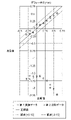
- FIG. 4A is a graph showing the relationship between the average signal intensity and the defocus amount in the first waveform data and the first converted data; A change in average signal intensity between the first waveform data and the first conversion data when the defocus amount is changed was verified.
- the position where the focal position of the laser light is in the vicinity of the surface of the workpiece is set to 0 mm defocus, and the first waveform data and the first conversion when the focal position of the laser light moves away from the surface of the workpiece got the data.
- the average signal intensity is the normalized first waveform data as shown in FIG. 3A and the normalized first conversion data as shown in FIG. 3B, for example, between 1 ms and 4 ms. shows the average value of the signal strength of
- the first laser light, first reflected light, first visible light, and first thermal radiation show average signal intensities of the first waveform data based on the detection values of the first device 300.
- the first waveform data is normalized so that the average signal intensity of the first laser light is 1V.
- the second laser light, the second reflected light, the second visible light, and the second thermal radiation are generated by multiplying the second waveform data based on the detection values of the second device 400 by respective predetermined coefficients.
- 3 shows the average signal intensity of the first converted data obtained by the conversion.
- the first conversion data is similarly normalized so that the average signal intensity of the second laser light is 1V.
- the processing state estimated from the first waveform data based on the first estimation model and the processing state estimated from the first conversion data based on the first estimation model have substantially the same results.
- the information converting section 22 of the machining state estimating device 200 converts the first converted data obtained by converting the second waveform data based on the detection value of the second device 400 .
- the estimation unit 23 can estimate the machining state based on the first estimation model with the first conversion data as input. That is, the second device 400 can use the first estimation model generated using the first waveform data based on the detection values of the first device 300 .
- FIG. 4B shows the relationship between the correct value and the estimated value when the first conversion data and the second waveform data are input data when estimating the machining state based on the first estimation model in the machining state estimation device 200.
- the information conversion unit 22 converts the second waveform data into the first conversion data, and the estimated value obtained by inputting the first conversion data to the estimation unit 23 has an error of ⁇ 0.15 mm from the correct value. is within. In the present embodiment, it is sufficient that a defocus of approximately 0.5 mm can be discriminated, so it can be seen that sufficiently practical estimation results are obtained.
- the first device 300 different from the device used in the production line acquires sensing data suitable for various processing conditions, and uses the first waveform data based on the sensing data. Generate an inference model. Therefore, an estimation model with higher estimation accuracy can be generated.
- the first conversion data is generated from the second waveform data based on the sensing data in the second device 400 used in the production line.
- the estimating unit 23 of the processing state estimation device 200 receives the first conversion data as an input, so that the first estimation model can be used to predict the processing state with higher accuracy even if there is a difference between the sensors of the devices.
- the estimated result can be output. That is, a first estimation model based on the sensing data of the first device 300 can be used to estimate the processing state of other devices, including the second device 400 .
- Embodiment 2 (Embodiment 2) Embodiment 2 will be described with reference to FIGS. 5A and 5B.
- symbol is attached
- FIG. the description overlapping with the first embodiment is omitted.
- FIG. 5A is a block diagram showing the estimation model generation device 110 according to the second embodiment.
- FIG. 5B is a block diagram showing the machining state estimation device 210 according to the second embodiment.
- the second embodiment differs from the first embodiment in that the estimated model generation device 110 includes the information conversion unit 17 and the machining state estimation device 210 does not include the information conversion unit.
- Embodiment 1 is configured such that the first estimation model based on the sensing data of the first device 300 generated by the estimation model generation device 100 can also be used for estimating the machining state of the second device 400 .
- the estimated model generating device 110 generates a second estimated model for estimating the machining state of the first device 300 and a third model for estimating the machining state of the second device 400. Generate an estimation model.
- the estimation model generation device 110 includes an information acquisition unit 16, an information conversion unit 17, an estimation model generation unit 18, and a storage unit 19.
- the information acquisition unit 16 acquires the third waveform data and the fourth waveform data.
- the third waveform data is for at least two of the third thermal radiation, the third visible light, the third reflected light, and the third laser light observed during laser processing by the first apparatus 300 (see FIG. 1C).
- the fourth waveform data is for at least two of the fourth thermal radiation, the fourth visible light, the fourth reflected light, and the fourth laser light observed during laser processing by the second device 400 (see FIG. 1D). Including seventh and eighth waveforms. That is, the fourth waveform data corresponds to the second waveform data of the first embodiment.
- the information conversion unit 17 of the estimation model generation device 110 converts the third waveform data for the first device 300 according to the fourth waveform data for the second device 400, and converts the second conversion data to generate
- the information conversion section 17 converts the third waveform data into the second conversion data by multiplying the fifth waveform by the third coefficient and the sixth waveform by the fourth coefficient.
- the first coefficient in the first embodiment is calculated by the relationship between the first waveform and the third waveform
- the third coefficient in the second embodiment is calculated by the relationship between the fifth waveform and the seventh waveform.
- the fourth coefficient of the second embodiment is calculated from the relationship between the sixth waveform and the eighth waveform.
- the third coefficient and the fourth coefficient are determined so as to generate the second conversion data while maintaining the ratio of the average values of the seventh waveform and the eighth waveform.
- the estimation model generation unit 18 generates the second estimation model by performing machine learning using teacher data in which the third waveform data is used as an explanatory variable and the machining state is used as an objective variable.
- the second estimation model is an estimation model for estimating the machining state for the first device 300 .
- the estimation model generating unit 18 generates the third estimation model by performing machine learning using teacher data in which the second converted data is used as an explanatory variable and the processing state is used as an objective variable.
- a third estimation model is an estimation model for estimating the machining state for the second device 400 .
- the machining state estimation device 210 includes an information acquisition unit 26, an estimation unit 27, and a storage unit 28.
- Storage unit 28 stores the second estimation model and the third estimation model generated by estimation model generation device 110 .
- the information acquisition unit 26 acquires the third waveform data and the fourth waveform data.
- the estimation unit 28 estimates the machining state of the workpiece by the first device 300 from the third waveform data based on the second estimation model.
- the estimation unit 28 further estimates the machining state of the workpiece by the second device 400 from the fourth waveform data based on the third estimation model.
- the second waveform data for the second device 400 is converted at the time of estimation by the machining state estimating device 200, so that the first estimation model for the first device 300 is used to estimate the machining state. I explained an example to do.
- estimated model generation device 110 generates a second estimated model and a third estimated model for first device 300 and second device 400, respectively.
- the processing state estimating device 210 can estimate the processing state as an input to the estimating section 27 without particularly converting the fourth waveform data based on the detection value in the second device 400. can.
- the processing state estimation device 210 does not convert the waveform data, so the time required for estimation by the estimation section 27 can be shortened.
- the estimation model generation device and processing state estimation device are widely applicable to prediction of processing state in a processing device that performs laser processing.
Landscapes
- Engineering & Computer Science (AREA)
- Mechanical Engineering (AREA)
- Physics & Mathematics (AREA)
- Optics & Photonics (AREA)
- Plasma & Fusion (AREA)
- Artificial Intelligence (AREA)
- Evolutionary Computation (AREA)
- Quality & Reliability (AREA)
- Laser Beam Processing (AREA)
Priority Applications (3)
| Application Number | Priority Date | Filing Date | Title |
|---|---|---|---|
| CN202280016450.2A CN116940435B (zh) | 2021-02-25 | 2022-01-05 | 推定模型生成装置及加工状态推定装置 |
| JP2023502132A JP7641515B2 (ja) | 2021-02-25 | 2022-01-05 | 推定モデル生成装置および加工状態推定装置 |
| US18/236,167 US20230390871A1 (en) | 2021-02-25 | 2023-08-21 | Estimation model generation apparatus and processing state estimation device |
Applications Claiming Priority (2)
| Application Number | Priority Date | Filing Date | Title |
|---|---|---|---|
| JP2021-028761 | 2021-02-25 | ||
| JP2021028761 | 2021-02-25 |
Related Child Applications (1)
| Application Number | Title | Priority Date | Filing Date |
|---|---|---|---|
| US18/236,167 Continuation US20230390871A1 (en) | 2021-02-25 | 2023-08-21 | Estimation model generation apparatus and processing state estimation device |
Publications (1)
| Publication Number | Publication Date |
|---|---|
| WO2022181061A1 true WO2022181061A1 (ja) | 2022-09-01 |
Family
ID=83048851
Family Applications (1)
| Application Number | Title | Priority Date | Filing Date |
|---|---|---|---|
| PCT/JP2022/000133 Ceased WO2022181061A1 (ja) | 2021-02-25 | 2022-01-05 | 推定モデル生成装置および加工状態推定装置 |
Country Status (4)
| Country | Link |
|---|---|
| US (1) | US20230390871A1 (https=) |
| JP (1) | JP7641515B2 (https=) |
| CN (1) | CN116940435B (https=) |
| WO (1) | WO2022181061A1 (https=) |
Cited By (1)
| Publication number | Priority date | Publication date | Assignee | Title |
|---|---|---|---|---|
| US20240017358A1 (en) * | 2020-12-03 | 2024-01-18 | Jfe Steel Corporation | Position detection apparatus for seam portion and heating portion of welded steel pipe, manufacturing equipment for welded steel pipe, position detection method for seam portion and heating portion of welded steel pipe, manufacturing method for welded steel pipe, and quality control method for welded steel pipe |
Families Citing this family (1)
| Publication number | Priority date | Publication date | Assignee | Title |
|---|---|---|---|---|
| TWI890214B (zh) * | 2023-11-28 | 2025-07-11 | 財團法人金屬工業研究發展中心 | 雷射銲接系統、熔池深度函數取得方法以及熔池形貌特徵估算方法 |
Citations (5)
| Publication number | Priority date | Publication date | Assignee | Title |
|---|---|---|---|---|
| JP2000153379A (ja) * | 1998-11-19 | 2000-06-06 | Sumitomo Heavy Ind Ltd | レーザ溶接の溶接状態判定方法および溶接状態判定装置 |
| JP2020175425A (ja) * | 2019-04-19 | 2020-10-29 | ファナック株式会社 | レーザ加工機の焦点位置ずれを学習する機械学習装置及び機械学習方法、並びに焦点位置ずれを補正するレーザ加工システム |
| JP2020189305A (ja) * | 2019-05-20 | 2020-11-26 | パナソニックIpマネジメント株式会社 | レーザ加工システム、学習装置および学習装置の学習方法 |
| JP6818970B1 (ja) * | 2020-05-20 | 2021-01-27 | 三菱電機株式会社 | データ作成装置、機械学習システムおよび加工状態推定システム |
| JP2021007957A (ja) * | 2019-06-28 | 2021-01-28 | 株式会社安川電機 | 評価装置、評価方法、評価システムおよび評価プログラム |
Family Cites Families (7)
| Publication number | Priority date | Publication date | Assignee | Title |
|---|---|---|---|---|
| GB9321866D0 (en) * | 1993-10-22 | 1993-12-15 | Kinsman Grant | Fuzzy logic control of laser welding |
| JP4792901B2 (ja) * | 2005-09-30 | 2011-10-12 | 日産自動車株式会社 | レーザ溶接装置およびその方法、ならびに照射装置 |
| JP5947740B2 (ja) * | 2013-03-29 | 2016-07-06 | トヨタ自動車株式会社 | 溶接部の検査装置とその検査方法 |
| JP6339603B2 (ja) * | 2016-01-28 | 2018-06-06 | ファナック株式会社 | レーザ加工開始条件を学習する機械学習装置、レーザ装置および機械学習方法 |
| JP6625914B2 (ja) * | 2016-03-17 | 2019-12-25 | ファナック株式会社 | 機械学習装置、レーザ加工システムおよび機械学習方法 |
| JP6680809B2 (ja) * | 2018-01-09 | 2020-04-15 | ファナック株式会社 | ファイバレーザ装置及び機械学習装置 |
| WO2020082385A1 (zh) * | 2018-10-26 | 2020-04-30 | 合刃科技(深圳)有限公司 | 激光加工参数与反射光谱的预测模型训练方法及装置 |
-
2022
- 2022-01-05 WO PCT/JP2022/000133 patent/WO2022181061A1/ja not_active Ceased
- 2022-01-05 JP JP2023502132A patent/JP7641515B2/ja active Active
- 2022-01-05 CN CN202280016450.2A patent/CN116940435B/zh active Active
-
2023
- 2023-08-21 US US18/236,167 patent/US20230390871A1/en active Pending
Patent Citations (5)
| Publication number | Priority date | Publication date | Assignee | Title |
|---|---|---|---|---|
| JP2000153379A (ja) * | 1998-11-19 | 2000-06-06 | Sumitomo Heavy Ind Ltd | レーザ溶接の溶接状態判定方法および溶接状態判定装置 |
| JP2020175425A (ja) * | 2019-04-19 | 2020-10-29 | ファナック株式会社 | レーザ加工機の焦点位置ずれを学習する機械学習装置及び機械学習方法、並びに焦点位置ずれを補正するレーザ加工システム |
| JP2020189305A (ja) * | 2019-05-20 | 2020-11-26 | パナソニックIpマネジメント株式会社 | レーザ加工システム、学習装置および学習装置の学習方法 |
| JP2021007957A (ja) * | 2019-06-28 | 2021-01-28 | 株式会社安川電機 | 評価装置、評価方法、評価システムおよび評価プログラム |
| JP6818970B1 (ja) * | 2020-05-20 | 2021-01-27 | 三菱電機株式会社 | データ作成装置、機械学習システムおよび加工状態推定システム |
Cited By (2)
| Publication number | Priority date | Publication date | Assignee | Title |
|---|---|---|---|---|
| US20240017358A1 (en) * | 2020-12-03 | 2024-01-18 | Jfe Steel Corporation | Position detection apparatus for seam portion and heating portion of welded steel pipe, manufacturing equipment for welded steel pipe, position detection method for seam portion and heating portion of welded steel pipe, manufacturing method for welded steel pipe, and quality control method for welded steel pipe |
| US12358081B2 (en) * | 2020-12-03 | 2025-07-15 | Jfe Steel Corporation | Position detection apparatus for seam portion and heating portion of welded steel pipe, manufacturing equipment for welded steel pipe, position detection method for seam portion and heating portion of welded steel pipe, manufacturing method for welded steel pipe, and quality control method for welded steel pipe |
Also Published As
| Publication number | Publication date |
|---|---|
| CN116940435B (zh) | 2026-04-07 |
| JP7641515B2 (ja) | 2025-03-07 |
| CN116940435A (zh) | 2023-10-24 |
| JPWO2022181061A1 (https=) | 2022-09-01 |
| US20230390871A1 (en) | 2023-12-07 |
Similar Documents
| Publication | Publication Date | Title |
|---|---|---|
| WO2022181061A1 (ja) | 推定モデル生成装置および加工状態推定装置 | |
| JP5587700B2 (ja) | 溶接部における欠陥のタイプ及び重度を分類するための方法及びシステム | |
| JP2019023622A (ja) | センサおよびシステムにより取得された信号に対してノイズ除去オペレーションを実行するための方法 | |
| JP5043881B2 (ja) | レーザ溶接モニタ装置及びレーザ溶接モニタ方法 | |
| JP5570451B2 (ja) | レーザ溶接装置およびレーザ溶接方法 | |
| US20230390863A1 (en) | Laser machining condition determination method and determination device | |
| JP7787261B2 (ja) | 溶接における溶け込み不良の検出方法及び関連装置 | |
| AU2025271380A1 (en) | Improvements In And Relating To Ultrasound Probes | |
| CN104062358A (zh) | 超声波检查装置以及超声波检查方法 | |
| CN107389244A (zh) | 一种激光盲孔残余应力检测装置及开发软件 | |
| CN115990720A (zh) | 用于监控激光加工过程的方法和系统、激光加工方法和激光加工系统 | |
| JP3184962B2 (ja) | レーザ溶接の溶接状態検出方法 | |
| US20230384282A1 (en) | Determination method and determination device for laser processing state | |
| US4924105A (en) | Optical measuring device with alternately-activated detection | |
| CN112518122A (zh) | 激光加工件熔深检测方法、装置和系统 | |
| CN118051871A (zh) | 基于多源数据融合的激光焊接过程监控方法、系统及介质 | |
| JP5187121B2 (ja) | レーザ加工装置およびレーザ加工方法 | |
| US20250387851A1 (en) | Inspection method and inspection device for workpiece in laser machining | |
| JP5183369B2 (ja) | レーザ溶接システムの異常検出方法 | |
| JP2010107470A (ja) | ディスパーション干渉計及び被測定物の物理量の計測方法 | |
| JP2023166927A (ja) | レーザ加工状態の判定方法及び判定装置 | |
| WO2019179550A8 (de) | Vorrichtung zur laserbearbeitung eines werkstücks, verwendung und verfahren | |
| TW201521954A (zh) | 用於顫振監控之訊噪分離方法與裝置 | |
| Park et al. | Development of a weld quality monitoring system in CO 2 laser welding by using photodiodes | |
| US20250058408A1 (en) | Machining condition determination method and determination device |
Legal Events
| Date | Code | Title | Description |
|---|---|---|---|
| 121 | Ep: the epo has been informed by wipo that ep was designated in this application |
Ref document number: 22759104 Country of ref document: EP Kind code of ref document: A1 |
|
| WWE | Wipo information: entry into national phase |
Ref document number: 2023502132 Country of ref document: JP |
|
| WWE | Wipo information: entry into national phase |
Ref document number: 202280016450.2 Country of ref document: CN |
|
| NENP | Non-entry into the national phase |
Ref country code: DE |
|
| 122 | Ep: pct application non-entry in european phase |
Ref document number: 22759104 Country of ref document: EP Kind code of ref document: A1 |