WO2022180933A1 - ヘッドアップディスプレイシステム - Google Patents
ヘッドアップディスプレイシステム Download PDFInfo
- Publication number
- WO2022180933A1 WO2022180933A1 PCT/JP2021/040066 JP2021040066W WO2022180933A1 WO 2022180933 A1 WO2022180933 A1 WO 2022180933A1 JP 2021040066 W JP2021040066 W JP 2021040066W WO 2022180933 A1 WO2022180933 A1 WO 2022180933A1
- Authority
- WO
- WIPO (PCT)
- Prior art keywords
- light guide
- light
- axis
- incident
- emitted
- Prior art date
- Legal status (The legal status is an assumption and is not a legal conclusion. Google has not performed a legal analysis and makes no representation as to the accuracy of the status listed.)
- Ceased
Links
Images







Classifications
-
- G—PHYSICS
- G02—OPTICS
- G02B—OPTICAL ELEMENTS, SYSTEMS OR APPARATUS
- G02B27/00—Optical systems or apparatus not provided for by any of the groups G02B1/00 - G02B26/00, G02B30/00
- G02B27/01—Head-up displays
- G02B27/0101—Head-up displays characterised by optical features
-
- B—PERFORMING OPERATIONS; TRANSPORTING
- B60—VEHICLES IN GENERAL
- B60K—ARRANGEMENT OR MOUNTING OF PROPULSION UNITS OR OF TRANSMISSIONS IN VEHICLES; ARRANGEMENT OR MOUNTING OF PLURAL DIVERSE PRIME-MOVERS IN VEHICLES; AUXILIARY DRIVES FOR VEHICLES; INSTRUMENTATION OR DASHBOARDS FOR VEHICLES; ARRANGEMENTS IN CONNECTION WITH COOLING, AIR INTAKE, GAS EXHAUST OR FUEL SUPPLY OF PROPULSION UNITS IN VEHICLES
- B60K35/00—Instruments specially adapted for vehicles; Arrangement of instruments in or on vehicles
- B60K35/10—Input arrangements, i.e. from user to vehicle, associated with vehicle functions or specially adapted therefor
-
- B—PERFORMING OPERATIONS; TRANSPORTING
- B60—VEHICLES IN GENERAL
- B60K—ARRANGEMENT OR MOUNTING OF PROPULSION UNITS OR OF TRANSMISSIONS IN VEHICLES; ARRANGEMENT OR MOUNTING OF PLURAL DIVERSE PRIME-MOVERS IN VEHICLES; AUXILIARY DRIVES FOR VEHICLES; INSTRUMENTATION OR DASHBOARDS FOR VEHICLES; ARRANGEMENTS IN CONNECTION WITH COOLING, AIR INTAKE, GAS EXHAUST OR FUEL SUPPLY OF PROPULSION UNITS IN VEHICLES
- B60K35/00—Instruments specially adapted for vehicles; Arrangement of instruments in or on vehicles
- B60K35/20—Output arrangements, i.e. from vehicle to user, associated with vehicle functions or specially adapted therefor
- B60K35/21—Output arrangements, i.e. from vehicle to user, associated with vehicle functions or specially adapted therefor using visual output, e.g. blinking lights or matrix displays
- B60K35/23—Head-up displays [HUD]
-
- B—PERFORMING OPERATIONS; TRANSPORTING
- B60—VEHICLES IN GENERAL
- B60K—ARRANGEMENT OR MOUNTING OF PROPULSION UNITS OR OF TRANSMISSIONS IN VEHICLES; ARRANGEMENT OR MOUNTING OF PLURAL DIVERSE PRIME-MOVERS IN VEHICLES; AUXILIARY DRIVES FOR VEHICLES; INSTRUMENTATION OR DASHBOARDS FOR VEHICLES; ARRANGEMENTS IN CONNECTION WITH COOLING, AIR INTAKE, GAS EXHAUST OR FUEL SUPPLY OF PROPULSION UNITS IN VEHICLES
- B60K35/00—Instruments specially adapted for vehicles; Arrangement of instruments in or on vehicles
- B60K35/20—Output arrangements, i.e. from vehicle to user, associated with vehicle functions or specially adapted therefor
- B60K35/21—Output arrangements, i.e. from vehicle to user, associated with vehicle functions or specially adapted therefor using visual output, e.g. blinking lights or matrix displays
- B60K35/23—Head-up displays [HUD]
- B60K35/231—Head-up displays [HUD] characterised by their arrangement or structure for integration into vehicles
-
- B—PERFORMING OPERATIONS; TRANSPORTING
- B60—VEHICLES IN GENERAL
- B60K—ARRANGEMENT OR MOUNTING OF PROPULSION UNITS OR OF TRANSMISSIONS IN VEHICLES; ARRANGEMENT OR MOUNTING OF PLURAL DIVERSE PRIME-MOVERS IN VEHICLES; AUXILIARY DRIVES FOR VEHICLES; INSTRUMENTATION OR DASHBOARDS FOR VEHICLES; ARRANGEMENTS IN CONNECTION WITH COOLING, AIR INTAKE, GAS EXHAUST OR FUEL SUPPLY OF PROPULSION UNITS IN VEHICLES
- B60K35/00—Instruments specially adapted for vehicles; Arrangement of instruments in or on vehicles
- B60K35/60—Instruments characterised by their location or relative disposition in or on vehicles
-
- B—PERFORMING OPERATIONS; TRANSPORTING
- B60—VEHICLES IN GENERAL
- B60K—ARRANGEMENT OR MOUNTING OF PROPULSION UNITS OR OF TRANSMISSIONS IN VEHICLES; ARRANGEMENT OR MOUNTING OF PLURAL DIVERSE PRIME-MOVERS IN VEHICLES; AUXILIARY DRIVES FOR VEHICLES; INSTRUMENTATION OR DASHBOARDS FOR VEHICLES; ARRANGEMENTS IN CONNECTION WITH COOLING, AIR INTAKE, GAS EXHAUST OR FUEL SUPPLY OF PROPULSION UNITS IN VEHICLES
- B60K35/00—Instruments specially adapted for vehicles; Arrangement of instruments in or on vehicles
- B60K35/80—Arrangements for controlling instruments
- B60K35/81—Arrangements for controlling instruments for controlling displays
-
- G—PHYSICS
- G02—OPTICS
- G02B—OPTICAL ELEMENTS, SYSTEMS OR APPARATUS
- G02B27/00—Optical systems or apparatus not provided for by any of the groups G02B1/00 - G02B26/00, G02B30/00
- G02B27/0081—Optical systems or apparatus not provided for by any of the groups G02B1/00 - G02B26/00, G02B30/00 with means for altering, e.g. enlarging, the entrance or exit pupil
-
- G—PHYSICS
- G02—OPTICS
- G02B—OPTICAL ELEMENTS, SYSTEMS OR APPARATUS
- G02B27/00—Optical systems or apparatus not provided for by any of the groups G02B1/00 - G02B26/00, G02B30/00
- G02B27/10—Beam splitting or combining systems
- G02B27/1086—Beam splitting or combining systems operating by diffraction only
-
- G—PHYSICS
- G02—OPTICS
- G02B—OPTICAL ELEMENTS, SYSTEMS OR APPARATUS
- G02B6/00—Light guides; Structural details of arrangements comprising light guides and other optical elements, e.g. couplings
- G02B6/0001—Light guides; Structural details of arrangements comprising light guides and other optical elements, e.g. couplings specially adapted for lighting devices or systems
- G02B6/0011—Light guides; Structural details of arrangements comprising light guides and other optical elements, e.g. couplings specially adapted for lighting devices or systems the light guides being planar or of plate-like form
- G02B6/0013—Means for improving the coupling-in of light from the light source into the light guide
- G02B6/0015—Means for improving the coupling-in of light from the light source into the light guide provided on the surface of the light guide or in the bulk of it
- G02B6/0016—Grooves, prisms, gratings, scattering particles or rough surfaces
-
- G—PHYSICS
- G02—OPTICS
- G02B—OPTICAL ELEMENTS, SYSTEMS OR APPARATUS
- G02B6/00—Light guides; Structural details of arrangements comprising light guides and other optical elements, e.g. couplings
- G02B6/0001—Light guides; Structural details of arrangements comprising light guides and other optical elements, e.g. couplings specially adapted for lighting devices or systems
- G02B6/0011—Light guides; Structural details of arrangements comprising light guides and other optical elements, e.g. couplings specially adapted for lighting devices or systems the light guides being planar or of plate-like form
- G02B6/0033—Means for improving the coupling-out of light from the light guide
- G02B6/0035—Means for improving the coupling-out of light from the light guide provided on the surface of the light guide or in the bulk of it
- G02B6/0038—Linear indentations or grooves, e.g. arc-shaped grooves or meandering grooves, extending over the full length or width of the light guide
-
- B—PERFORMING OPERATIONS; TRANSPORTING
- B60—VEHICLES IN GENERAL
- B60K—ARRANGEMENT OR MOUNTING OF PROPULSION UNITS OR OF TRANSMISSIONS IN VEHICLES; ARRANGEMENT OR MOUNTING OF PLURAL DIVERSE PRIME-MOVERS IN VEHICLES; AUXILIARY DRIVES FOR VEHICLES; INSTRUMENTATION OR DASHBOARDS FOR VEHICLES; ARRANGEMENTS IN CONNECTION WITH COOLING, AIR INTAKE, GAS EXHAUST OR FUEL SUPPLY OF PROPULSION UNITS IN VEHICLES
- B60K2360/00—Indexing scheme associated with groups B60K35/00 or B60K37/00 relating to details of instruments or dashboards
- B60K2360/20—Optical features of instruments
- B60K2360/33—Illumination features
- B60K2360/334—Projection means
-
- B—PERFORMING OPERATIONS; TRANSPORTING
- B60—VEHICLES IN GENERAL
- B60K—ARRANGEMENT OR MOUNTING OF PROPULSION UNITS OR OF TRANSMISSIONS IN VEHICLES; ARRANGEMENT OR MOUNTING OF PLURAL DIVERSE PRIME-MOVERS IN VEHICLES; AUXILIARY DRIVES FOR VEHICLES; INSTRUMENTATION OR DASHBOARDS FOR VEHICLES; ARRANGEMENTS IN CONNECTION WITH COOLING, AIR INTAKE, GAS EXHAUST OR FUEL SUPPLY OF PROPULSION UNITS IN VEHICLES
- B60K2360/00—Indexing scheme associated with groups B60K35/00 or B60K37/00 relating to details of instruments or dashboards
- B60K2360/20—Optical features of instruments
- B60K2360/33—Illumination features
- B60K2360/336—Light guides
-
- G—PHYSICS
- G02—OPTICS
- G02B—OPTICAL ELEMENTS, SYSTEMS OR APPARATUS
- G02B27/00—Optical systems or apparatus not provided for by any of the groups G02B1/00 - G02B26/00, G02B30/00
- G02B27/01—Head-up displays
- G02B27/0101—Head-up displays characterised by optical features
- G02B2027/013—Head-up displays characterised by optical features comprising a combiner of particular shape, e.g. curvature
-
- G—PHYSICS
- G02—OPTICS
- G02B—OPTICAL ELEMENTS, SYSTEMS OR APPARATUS
- G02B27/00—Optical systems or apparatus not provided for by any of the groups G02B1/00 - G02B26/00, G02B30/00
- G02B27/01—Head-up displays
- G02B2027/0192—Supplementary details
- G02B2027/0196—Supplementary details having transparent supporting structure for display mounting, e.g. to a window or a windshield
Definitions
- the present disclosure relates to a head-up display system that displays virtual images.
- a vehicle information projection system that displays augmented reality (AR) using a head-up display device.
- a head-up display device projects light representing a virtual image onto the windshield of the vehicle, thereby allowing the driver to visually recognize the virtual image together with the actual scenery outside the vehicle.
- Patent Document 1 describes an optical element provided with a waveguide (light guide) for expanding the exit pupil in two directions.
- the optical element can utilize a diffractive optical element to expand the exit pupil.
- Document 2 describes a head-mounted display that performs augmented reality (AR) display using a volume hologram diffraction grating.
- AR augmented reality
- the light guide when implementing the pupil dilation hologram used in head-mounted displays in a head-up display, the light guide requires fine processing, making it difficult to manufacture.
- the present disclosure provides a head-up display system that facilitates the manufacture of light guides.
- a head-up display system of the present disclosure is a head-up display system that displays a virtual image superimposed on a real scene that is visible through a translucent member, and includes a display unit that emits a luminous flux that is visually recognized by an observer as a virtual image; and a light guide that guides the light flux to the translucent member.
- the light guide has an incident surface on which the light flux from the display section is incident and an exit surface from which the light flux exits from the light guide.
- a light ray at the center of the light flux emitted from the display unit enters the incident surface of the light guide while being inclined with respect to the normal line direction of the incident surface.
- the direction in which the observer visually recognizes the virtual image from the viewing area of the virtual image is defined as the Z-axis direction
- the horizontal direction orthogonal to the Z-axis is defined as the X-axis direction
- the direction orthogonal to the XZ plane formed by the X-axis and the Z-axis is defined as the Y-axis.
- a light beam at the center of the light flux emitted from the light guide is inclined with respect to the normal line direction of the emission surface of the light guide and emitted toward the translucent member.
- the light guide body is inclined with respect to the Z-axis in a cross-sectional view of the YZ plane formed by the Y-axis and the Z-axis, and the light guide body is arranged so as to be inclined with respect to the translucent member in the cross-sectional view of the YZ plane. ing.
- a light flux emitted from the light guide enters the translucent member while being inclined with respect to the Z-axis in a cross-sectional view of the YZ plane.
- the head-up display system of the present disclosure is a head-up display system that displays a virtual image superimposed on a real scene that is visible through a translucent member, and is a display unit that emits a luminous flux that is visually recognized by an observer as a virtual image. and a light guide that guides the light flux to the translucent member.
- the light guide has an incident surface on which a light beam from the display portion is incident, a coupling area for changing the traveling direction of the light beam incident on the incident surface, and a plurality of light beams propagated from the coupling area in a first direction.
- the center ray of the luminous flux emitted from the display unit is incident at an angle with respect to the normal line direction of the incident surface of the light guide.
- the direction in which the observer visually recognizes the virtual image from the viewing area of the virtual image is defined as the Z-axis direction
- the horizontal direction orthogonal to the Z-axis is defined as the X-axis direction
- the direction orthogonal to the XZ plane formed by the X-axis and the Z-axis is defined as the Y-axis.
- a luminous flux incident on the coupling region and having its traveling direction changed is propagated to the first expansion region, and the luminous flux is duplicated in the first horizontal direction to be expanded in the second expansion region. Propagate to area.
- the luminous flux is duplicated in the second direction and emitted from the emission surface, and the central ray of the luminous flux emitted from the light guide is inclined with respect to the normal direction of the emission surface of the light guide.
- the light is emitted toward the translucent member.
- the light guide body is inclined with respect to the Z-axis in a cross-sectional view of the YZ plane formed by the Y-axis and the Z-axis, and the light guide body is arranged so as to be inclined with respect to the translucent member in the cross-sectional view of the YZ plane. ing.
- a light flux emitted from the light guide enters the translucent member while being inclined with respect to the Z-axis in a cross-sectional view of the YZ plane.
- manufacturing of the light guide can be facilitated.
- FIG. 1 is a schematic diagram showing the configuration of the light guide 13.
- a so-called pupil expansion type light guide 13 is used in a head-mounted display (hereinafter referred to as HMD) or the like.
- the pupil-expanding light guide 13 includes a coupling region 21 that receives image light from the display unit 11 and changes the direction of travel, a first expansion region 23 that expands in the first direction, and an expansion region that expands in the second direction. and a second expansion region 25 that expands.
- the first direction and the second direction may intersect each other, eg, be orthogonal.
- the coupling region 21, the first expansion region 23, and the second expansion region 25 each have diffraction power for diffracting image light, and are formed as embossed holograms or volume holograms.
- An embossed hologram is, for example, a diffraction grating.
- a volume hologram is, for example, interference fringes formed by a dielectric film.
- the coupling region 21 changes the traveling direction of the image light incident from the outside so that it is directed toward the first expansion region 23 by diffraction power.
- a diffraction grating element is arranged in the first expansion region 23, and the incident image light is divided by diffraction power into image light traveling in the first direction and image light traveling to the second expansion region 25. to duplicate the image light.
- diffraction grating elements are arranged at four points 23p aligned in the direction in which the image light travels through repeated total reflections.
- a diffraction grating element splits the image light at each point 23 p and causes the split image light to travel to the second extension region 25 .
- the incident image light flux is expanded by being duplicated into four image light fluxes in the first direction.
- a diffraction grating element is arranged in the second expansion region 25, and the incident image light is divided into image light traveling in the second direction by diffraction power and image light emitted to the outside from the second expansion region 25.
- the image light is duplicated by dividing into .
- three points 25p arranged in the direction in which the image light travels by repeating total reflection are arranged in each row, and a total of 12 points 25p in four rows each have a diffraction grating. elements are placed.
- the image light is split at each point 25p, and the split image light is emitted to the outside.
- the light guide 13 can duplicate 12 image light beams from one incident image light beam, and duplicate the light beams in the first direction and the second direction, respectively. can be used to extend the viewing area.
- the observer can visually recognize each of the 12 image light beams as a virtual image, and the visual recognition area in which the image light can be visually recognized by the observer can be widened.
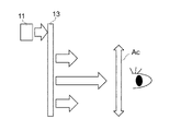
- FIG. 2 is an explanatory diagram showing incident light and outgoing light of the HMD.
- FIG. 3 is an explanatory diagram showing incident light and outgoing light of the HUD.
- the light guide 13 in the HMD is substantially facing the visual recognition area Ac in which the virtual image can be visually recognized by the observer.
- the image light vertically incident from the display unit 11 is split within the light guide 13, and the split image light is emitted from the emission surface 27 of the light guide 13 perpendicularly toward the visual recognition area Ac.
- the image light emitted from the light guide 13 is reflected by the windshield 5, for example, and enters the visual recognition area Ac, so that divided image light is guided.
- the light is emitted obliquely from the emission surface 27 of the light body 13 .
- the inventors newly discovered that making the image light obliquely incident on the light guide 13 from the display unit 11 facilitates the optical design.
- the inventors have newly discovered that the direction of the image emitted from the light guide 13 is different between the HMD and the HUD, and that the HUD can be manufactured easily by using this characteristic.
- the configuration of the present disclosure will be further described below.
- FIG. 4 is a cross-sectional view of a vehicle 3 equipped with a HUD system 1 according to the present disclosure.
- FIG. 5 is an explanatory diagram showing optical paths of light beams emitted from the display section.
- a HUD system 1 mounted on a vehicle 3 will be described as an example.
- directions for the HUD system 1 will be described based on the X, Y, and Z axes shown in FIG.
- the Z-axis direction is the direction in which the observer visually recognizes the virtual image Iv from the visual recognition area Ac in which the observer can visually recognize the virtual image Iv.
- the X-axis direction is a horizontal direction orthogonal to the Z-axis.
- the Y-axis direction is a direction orthogonal to the XZ plane formed by the X-axis and the Z-axis. Therefore, the X-axis direction corresponds to the horizontal direction of the vehicle 3 , the Y-axis direction corresponds to the vertical direction of the vehicle 3 , and the Z-axis direction corresponds to the forward direction of the vehicle 3 .
- the HUD system 1 is arranged inside the dashboard (not shown) below the windshield 5 of the vehicle 3 .
- Observer D recognizes the image projected from HUD system 1 as virtual image Iv.
- the HUD system 1 displays the virtual image Iv superimposed on the real scene visible through the windshield 5 . Since a plurality of duplicated images are projected onto the visible area Ac, a hologram that is displayed as an image within the visible area Ac even if the position of the observer's eyes is shifted in the Y-axis direction and the X-axis direction. can be visually recognized.
- the observer D is a human being in the vehicle 3 as a moving object, for example, a driver.
- the HUD system 1 includes a display section 11, a light guide 13, and a control section 15.
- the display unit 11 displays an image displayed as the virtual image Iv.
- the light guide 13 divides and copies the light beam L1 emitted from the display unit 11 and guides the duplicated light beam L2 to the windshield 5 .
- the display unit 11 displays an image based on control by an external control unit.
- a liquid crystal display device with backlight Liquid Crystal Display
- an organic light-emitting diode Organic Light-Emitting Diode
- a plasma display or the like
- an image may be generated using a screen that diffuses or reflects light, a projector, or a scanning laser.
- the display unit 11 can display image contents including various information such as a road progress guide display, a distance to a vehicle in front, the remaining battery level of the vehicle, and the current vehicle speed. In this way, the display unit 11 emits a light flux L1 including image content that is visually recognized by the observer D as the virtual image Iv.
- the control unit 15 can be realized by a semiconductor element or the like.
- the control unit 15 can be configured by, for example, a microcomputer, CPU, MPU, GPU, DSP, FPGA, or ASIC.
- the control unit 15 reads data and programs stored in a built-in storage unit (not shown) and performs various arithmetic processing, thereby realizing predetermined functions.
- the control unit 15 includes a storage device 17 .
- the storage device 17 is a storage medium that stores programs and data necessary for realizing the functions of the control unit 15 .
- the storage device 17 can be implemented by, for example, a hard disk (HDD), SSD, RAM, DRAM, ferroelectric memory, flash memory, magnetic disk, or a combination thereof.
- the storage device 17 stores a plurality of image data representing the virtual image Iv.
- the control unit 15 determines the virtual image Iv to be displayed based on vehicle-related information acquired from the outside.
- the control unit 15 reads the image data of the determined virtual image Iv from the storage unit and outputs it to the display unit 11 .
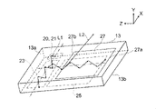
- FIG. 5 is a see-through perspective view showing the structure of the light guide 13.
- the light guide 13 has a first major surface 13a and a second major surface 13b.
- the first main surface 13a and the second main surface 13b face each other.
- the lightguide 13 has an entrance surface 20 , a coupling area 21 , a first extension area 23 , a second extension area 25 and an exit surface 27 .
- the entrance surface 20, the coupling region 21, the first extension region 23, and the second extension region 25 are included in the second major surface 13b, and the exit surface 27 is included in the first major surface 13a.
- the exit surface 27 faces the second extended region 25 .
- the coupling region 21, the first extension region 23, and the second extension region 25 may exist between the first major surface 13a and the second major surface 13b.
- the first principal surface 13 a faces the windshield 5 .
- the incident surface 20 is included in the coupling region 21 in the present embodiment, the incident surface 20 may be included in the first major surface 13a on the surface facing the coupling region 21 .
- the output surface 27 may be included in the second extended region 25 .
- the coupling region 21, the first expansion region 23, and the second expansion region 25 have different diffraction powers, and form diffraction gratings or volume holograms, respectively.
- the coupling region 21, the first expansion region 23, and the second expansion region 25 have different diffraction angles of the image light.
- the light guide 13 is configured such that the incident light flux is totally reflected inside.
- the light guide 13 includes in part a diffraction grating or a volume hologram that diffracts light.
- the combined area 21, the first extended area 23, and the second extended area 25 are three-dimensional areas when they contain volume holograms.
- the coupling area 21 is an area where the light beam L1 emitted from the display section 11 is incident from the incident surface 20 and changes the traveling direction of the light beam L1.
- the coupling region 21 has a diffractive power and changes the propagation direction of the incident light flux L1 toward the first extension region 23 .
- coupling is a state of propagating in the light guide 13 under total internal reflection conditions.
- the first expansion area 23 expands the luminous flux L1 in the first direction and emits it to the second expansion area.
- the length in the first direction is greater than the length in the second direction.
- the light guide 13 is arranged so that the first direction is the horizontal direction (X-axis direction).
- the luminous flux L1 propagated from the coupling region 21 propagates in the first direction while repeating total reflection on the first main surface 13a and the second main surface 13b.
- the beam L1 is duplicated by the diffraction grating of the expansion area 23 and emitted to the second expansion area.
- the second expansion area 25 expands the light flux L1 in, for example, a second direction perpendicular to the first direction, and emits the expanded light flux L2 from the emission surface 27.
- the second direction of the light guide 13 is arranged in the Z-axis direction.
- the light beam L1 propagated from the first expansion region 23 is formed on the second main surface 13b while propagating the light beam L1 in the second direction while repeating total reflection on the first main surface 13a and the second main surface 13b.
- the light beam L1 is duplicated by the diffraction grating of the second extended region 25 and emitted to the outside of the light guide 13 through the emission surface 27 .
- the light guide 13 directs the light beam L1, which has been incident on the incident surface 20 and whose traveling direction has been changed, in the horizontal direction (X-axis direction) of the virtual image Iv visually recognized by the observer D.
- the luminous flux L2 is emitted from the exit surface 27 after being further expanded in the vertical direction (Y-axis direction) of the virtual image Iv.
- the light guide 13 is inclined with respect to the Z-axis in a cross-sectional view of the YZ plane defined by the Y-axis and the Z-axis.
- the center ray of the light beam L1 emitted from the display unit 11 is incident on the coupling region 21 of the light guide 13 while being inclined with respect to the normal line direction of the incident surface 20 .
- a light ray at the center of the light beam L1 emitted from the display unit 11 is, for example, incident on the incident surface 20 while being inclined with respect to the normal direction of the center or the center of gravity.
- the central ray of the light beam L2 emitted from the light guide 13 is inclined with respect to the normal line direction of the emission surface 27 of the light guide 13 and emitted toward the windshield 5 .
- the central ray of the light beam L2 emitted from the light guide 13 is emitted toward the windshield 5 while being inclined with respect to the normal direction of the center or the center of gravity of the emission surface 27, for example.
- the light guide 13 is arranged below the visual recognition area Ac of the observer D when the Z axis passes through the visual recognition area Ac of the virtual image Iv in the direction in which the observer D visually recognizes the virtual image.
- the side of the exit surface 27 of the light guide 13 closer to the observer D is closer to the Z-axis, and the side of the exit surface 27 farther from the observer D is inclined away from the Z-axis in a cross-sectional view of the YZ plane.
- the distance Lg1 between the viewer-side side 27a of the output surface 27 and the Z-axis is smaller than the distance Lg2 between the display unit 11-side side 27b of the output surface 27 and the Z-axis.
- the sunlight incident on the light guide 13 through the windshield 5 can be reflected toward the windshield 5 .
- the sunlight reflected by the light guide 13 does not reach the visual recognition area Ac, so that the observer D can be prevented from being dazzled.
- the sunlight reflected by the light guide 13 can be prevented from reaching the visual recognition area Ac after being reflected by the windshield 5 and dazzling the observer D. can be done.
- the light guide 13 is arranged to be inclined with respect to the Z-axis in a cross-sectional view of the YZ plane with respect to the windshield 5. The light is incident on the windshield 5 at an angle.
- the light guide 13 Since the light guide 13 is arranged in this manner, the light flux L1 from the display section 11 is obliquely incident on the light guide 13, and the split and duplicated light flux L2 is obliquely emitted from the light guide 13 to the windshield. Emit toward 5.
- the coupling region 21 between the incident light and the light guide 13 is Either or both of the angular difference ⁇ in the normal direction and the angular difference ⁇ in the normal direction between the emitted light and the emission surface 27 of the light guide 13 is ⁇ degrees to 90- ⁇ degrees on the YZ plane. If either or both of the angular difference ⁇ and the angular difference ⁇ are less than ⁇ degrees in the YZ plane, the possibility of stray sunlight entering the visual recognition area Ac increases. It becomes difficult for D to visually recognize the virtual image Iv.
- the angle difference ⁇ and the angle difference ⁇ are in the angle range of ⁇ degrees to 90- ⁇ degrees on the YZ plane, the stray light of sunlight is reduced from entering the visual recognition area Ac, and the observation The person D can appropriately visually recognize the virtual image Iv.
- the angle ⁇ is, for example, 2 degrees to 3 degrees.
- the incident angle ⁇ of the light beam L2 emitted from the light guide 13 with respect to the windshield 5 is 45 degrees or more and 75 degrees or less
- the inclination angle ⁇ of the light guide 13 with respect to the Y axis is the windshield 5 and less than 175 degrees.
- the straight line indicated by reference numeral 41 is an imaginary straight line translated along the Y-axis.
- FIG. 9A is an explanatory diagram illustrating the order of pupil expansion of the light guide 13 of the embodiment.
- FIG. 9B is an explanatory diagram illustrating the wave vector of the light guide 13 of the embodiment. The projections and recesses of the diffraction grating are shown in each of the coupling region 21, the first extension region 23, and the second extension region 25 in FIG. 9A.
- the luminous flux L1 of the image light incident on the light guide 13 is directed to the first expansion region 23 for pupil expansion in the horizontal direction (negative direction of the X axis) as the first direction by the diffraction element formed in the coupling region 21. Change the direction of propagation. Therefore, after being obliquely incident on the coupling region 21, the light beam L1 propagates in the direction of the first extension region 23 under the action of the wave vector k1 shown in FIG. 9B.
- the light flux L1 propagating to the first expansion region 23 extending in the first direction is duplicated with the light flux L1 propagating in the first direction by the diffraction element formed in the first expansion region 23 while repeating total reflection. and a light beam L1 that changes its direction of propagation to the second extension region 25 .
- the duplicated light flux L1 propagates in the direction of the second extension region 25 under the action of the wave vector k2 shown in FIG. 9B.
- the light beam L1 whose propagation direction is changed to the second expansion region 25 extending along the negative direction of the Z-axis as the second direction is propagated in the second direction by the diffraction element formed in the second expansion region 25. and a beam L2 that is duplicated and emitted from the second expansion region 25 to the outside of the light guide 13 via the exit surface 27 .
- the duplicated light flux L2 propagates in the direction of the exit surface 27 under the action of the wave vector k3 shown in FIG. 9B.
- the magnitude of the wave vector k3 of the second expansion region 25 is can be made smaller. Since the magnitude of the wave vector k3 can be reduced, the diffraction power of the second expansion region 25 can be reduced and the pitch of the diffraction grating of the second expansion region 25 can be lengthened.
- the pitch of the diffraction gratings of the coupling region 21 and the first extension region 23 is about 300 nm, but the pitch of the diffraction grating of the second extension region 25 can be about 1 ⁇ m.
- the pitch of the diffraction grating of the second extended region 25, which has the widest area among the regions in which the diffraction elements are formed can be lengthened, so that the processing of the second extended region 25 is facilitated.
- the manufacture of the light guide 13 can be facilitated.
- FIG. 10A is an explanatory diagram illustrating the order of pupil dilation of the light guide 13A as a comparative example.
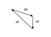
- the luminous flux L1 of the image light incident on the display unit 11 is propagated to the first expansion region 23A that expands the virtual image Iv in the vertical direction by the diffraction element formed in the coupling region 21A. to change Therefore, after being obliquely incident on the coupling region 21A, the light flux L1 propagates in the direction of the first extension region 23 under the action of the wave vector k4 shown in FIG. 10B.
- the light flux L1 propagating to the first expansion region 23 extending along the Z-axis direction is replicated by the diffraction element formed in the first expansion region 23A while undergoing total reflection, and is replicated into the light flux L1 propagating in the horizontal direction. 2 and a light beam L1 that changes direction of propagation to the extension region 25A.
- the duplicated light flux L1 propagates in the direction of the second extension region 25 under the action of the wave vector k5 shown in FIG. 10B.
- the light flux L1 whose propagation direction is changed to the second extended region 25A extending in the horizontal direction is duplicated with the light flux L1 propagating in the negative direction of the X-axis by the diffraction element formed in the second extended region 25A. 2 and a light flux L2 emitted from the expansion area 25A to the outside of the light guide 13 via the emission surface 27.
- the duplicated light beam L2 propagates in the direction of the exit surface 27 under the action of the wave vector k6 shown in FIG. 10B.
- the magnitude of the wave vector k6 of the second expansion region 25A is larger than in the embodiment. . Therefore, the diffraction power of the second extended region 25A of the comparative example must be made larger than that of the embodiment, and the pitch of the diffraction grating of the second extended region 25A must be shortened.
- the pitch of the diffraction grating in the coupling region 21 is about 1 ⁇ m
- the pitch of the diffraction grating in the second extension region 25 is about 300 nm.
- the pitch of the diffraction grating of the second extended region 25A which has the widest area among the regions in which the diffraction elements are formed, must be shortened, making it more difficult to process the second extended region 25A.
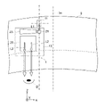
- the display section 11, the coupling region 21 of the light guide 13, and the second extension region 25 are arranged in this order in the negative direction of the Z axis.
- both the direction in which the light flux L1 from the display section 11 is incident on the light guide 13 and the direction in which the light flux L2 is emitted from the second extended region 25 to the windshield 5 can have components in the same direction.
- the diffraction power of the second extended region 25 can be reduced.
- the direction in which the light flux L1 from the display unit 11 is incident on the light guide 13 and the direction in which the light flux L2 is emitted from the second expansion region 25 to the windshield 5 are aligned along the negative direction of the Z axis.
- the HUD system 1 of the embodiment is arranged on the left side with respect to the center line 3a in the width direction of the vehicle 3, but may be arranged on the right side.
- the display unit 11 and the coupling region 21 of the light guide 13 may be arranged on the center line 3a side of the vehicle 3 with respect to the first extended region 23 of the light guide 13, or may be arranged on the opposite side. You may
- the distance on the Z axis from the visual recognition area Ac in which the visual recognition position of the observer D is included to the combined area 21 is the Z distance from the visual recognition area Ac to the emission surface 27. longer than the on-axis distance.
- the distance on the Z-axis from the visible area Ac to the joint area 21 is the distance from the visible area Ac to the intersection of the Z-axis and the perpendicular to the Z-axis from any point on the joint area 21 on the YZ plane. .
- the distance on the Z-axis between the emission surface 27 and the visual recognition area Ac is the distance from the visual recognition area Ac to the intersection of the Z-axis and the perpendicular line to the Z-axis from an arbitrary point on the emission surface 27 on the YZ plane.
- the light flux emitted from the display unit 11 is emitted toward the quadrant where the observer D is centered on the display unit 11 on either or both of the XZ plane and the YZ plane formed by the X axis and the Z axis.
- the difference between the angle of incidence of the light flux L1 on the light guide 13 and the angle of total reflection for guiding the light inside the light guide 13 becomes smaller, so the diffraction pitch of the second extended region 25 can be lengthened. and the diffraction efficiency increases. Thereby, the manufacture of the light guide 13 can be facilitated.
- the windshield 5 is a curved surface, and at least a part of the incident region of the light flux L2 is inclined in the cross-sectional view of the XZ plane and the cross-sectional view of the YZ plane.
- a light beam L1 emitted from the display unit 11 is incident on the incident surface 20 of the light guide 13 and emitted from the exit surface 27.
- the emission direction of the light flux L2 may be different.
- the display section 11 is arranged between the light guide 13 and the windshield 5 . Even in this case, the diffraction pitch of the second extended region 25 can be lengthened. are at the same angle, it is possible to prevent distortion of the image, thus facilitating the optical design.
- the light guide 13 is arranged to be inclined with respect to the windshield 5 in a cross-sectional view of the YZ plane.
- the light beams L1 are not emitted toward the quadrant where the observer D is located with the display unit 11 as the center in both the XZ plane and the YZ plane.
- the diffraction pitch can be lengthened, and the incident direction in which the light flux L1 emitted from the display section 11 is incident on the incident surface 20 of the coupling region 21 of the light guide 13 and the emission direction of the light flux L2 emitted from the emission surface 27 are can be in the same direction.
- the display unit 11 may be arranged closer to the visual recognition area Ac than the coupling area 21 of the light guide 13 in the Z-axis direction. good. Even in this case, the diffraction pitch of the second extended region 25 can be lengthened as in the embodiment.
- the display unit 11 is arranged between the light guide 13 and the windshield 5, and the display unit 11 is arranged between the light guide 13 and the windshield 5.
- the display unit 11 may be arranged closer to the visual recognition area Ac in the Z-axis direction than the coupling area 21 of .
- the diffraction pitch of the second extended region 25 can be lengthened as in the embodiment.
- the HUD system 1 of the present disclosure is a HUD system 1 that superimposes and displays a virtual image Iv on a real scene visible through a windshield 5 .
- a display unit 11 that emits a luminous flux that is visually recognized by an observer D as a virtual image Iv, and a light guide 13 that guides the luminous flux to the windshield 5 are provided.
- the light guide 13 has an incident surface 20 on which the light flux from the display section 11 is incident, and an exit surface 27 from which the light flux exits from the light guide 13 .
- a light beam at the center of the light flux emitted from the display unit 11 is incident on the incident surface 20 of the light guide 13 while being inclined with respect to the normal line direction.
- the direction in which the observer D visually recognizes the virtual image Iv from the visual recognition area Ac of the virtual image Iv is defined as the Z-axis direction
- the horizontal direction orthogonal to the Z-axis is defined as the X-axis direction
- the XZ plane formed by the X-axis and the Z-axis is orthogonal.
- Let the direction be the Y-axis direction.
- the luminous flux incident on the incident surface 20 of the light guide 13 changes its traveling direction in the light guide 13, and after being duplicated into a plurality of luminous fluxes in the horizontal direction of the virtual image Iv viewed by the observer D, the luminous flux is duplicated.
- the luminous flux is emitted from the exit surface 27 so as to expand the visual recognition area.
- the center ray of the light beam emitted from the light guide 13 is inclined with respect to the normal line direction of the emission surface 27 of the light guide 13 and is emitted toward the windshield 5 .
- the light guide 13 is inclined with respect to the Z-axis in a cross-sectional view of the YZ plane defined by the Y-axis and the Z-axis.
- the light guide 13 is arranged to be inclined with respect to the windshield 5 in a cross-sectional view of the YZ plane. 5.
- the luminous flux from the display unit 11 is obliquely emitted to the coupling region 21 of the light guide 13, and the luminous flux pupil-expanded by the light guide 13 is obliquely emitted from the emission surface 27 toward the windshield 5.
- the luminous flux incident on the incident surface of the light guide 13 and having its traveling direction changed is duplicated in the horizontal direction of the virtual image Iv visually recognized by the observer D, and then duplicated in the vertical direction to the exit surface. 27. Therefore, the diffractive power of the widest area of the light guide 13 that duplicates the light flux in the vertical direction can be reduced, so that the light guide 13 can be easily processed, and the HUD system 1 can be manufactured easily.
- the light guide 13 is arranged below the viewing area of the observer D, and the side of the exit surface 27 of the light guide 13 closer to the observer D is closer to the Z axis than the side farther from the viewing area Ac.
- the light guide 13 is inclined in a cross-sectional view of the YZ plane. Accordingly, since the light guide 13 is arranged to face the windshield 5, the sunlight incident through the windshield 5 can be reflected back toward the windshield 5 by the light guide 13. . As a result, it is possible to prevent the sunlight from being reflected by the light guide 13 and led to the visual recognition area Ac, thereby preventing the observer from being dazzled by the sunlight. Further, by adjusting the inclination angle of the light guide 13, the sunlight reflected by the light guide 13 can be prevented from reaching the visual recognition area Ac after being reflected by the windshield 5 and dazzling the observer D. can be done.
- the light guide 13 has a coupling region 21 that changes the traveling direction of the light beam incident on the incident surface 20 and a second region that horizontally copies the light beam whose traveling direction has been changed in the coupling region 21 within the light guide 13 . It has a first expansion area 23 and a second expansion area 25 for duplicating the luminous flux expanded in the first expansion area 23 in a direction crossing the horizontal direction within the light guide 13 .
- the coupling region 21, the first extension region 23, and the second extension region 25 have different diffraction powers and diffraction angles, respectively.
- the light beam duplicated in the second expansion area 25 is emitted from the emission surface 27 . As a result, the diffraction power of the second extended region 25 can be reduced, so the manufacture of the light guide 13 can be facilitated.
- the coupling region 21, the first expansion region 23, and the second expansion region 25 are regions having diffraction structures, and the magnitude of the wave vector of each diffraction structure is different.
- the wave vector k2 of the first extension region 23 is about 1.1 times the wave vector k1 of the coupling region 21, and the wave vector k3 of the second extension region 25 is about 0.3 times. Since the diffraction pitch of the diffraction structure of the second extended region 25 can be lengthened, the manufacturing of the light guide 13 can be facilitated.
- a virtual image Iv suitable for the observer D who drives the vehicle 3 can be displayed.
- the divided and duplicated light flux L2 is reflected by the windshield 5 to allow the observer D to visually recognize the virtual image Iv, but this is not the only option.
- k may be used to reflect the divided and duplicated light beam L2 to the combiner so that the observer D can visually recognize the virtual image Iv.
- the first direction in which the light flux L1 is expanded in the first expansion region 23 and the second direction in which the light flux L1 is expanded in the second expansion region 25 are orthogonal to each other, but the invention is not limited to this.
- the first expansion region 23 expands the light beam L1 in the first direction if the expansion component in the horizontal direction is larger than that in the direction along the Z axis.
- Expansion of the light flux L1 in the second direction at 25 may be achieved if the expansion component in the direction along the Z-axis is larger than that in the horizontal direction.
- the object to which the HUD system 1 is applied is not limited to the vehicle 3 .
- Objects to which the HUD system 1 is applied may be, for example, trains, motorcycles, ships, or aircraft, or may be amusement machines that do not involve movement.
- the light flux from the display section 11 is reflected by a transparent curved plate as a translucent member that reflects the light flux emitted from the display section 11.
- FIG. the actual scene that the user can visually recognize through the transparent curved plate may be an image displayed from another image display device. That is, the virtual image by the HUD system 1 may be superimposed on the video displayed from another video display device.
- any one of the windshield 5, the combiner, and the transparent curved plate may be employed as the translucent member in the present disclosure.
- a head-up display system of the present disclosure is a head-up display system that displays a virtual image superimposed on a real scene that is visible through a light-transmitting member. and a light guide that guides the light flux to the translucent member.
- the light guide has an incident surface on which the light flux from the display section is incident and an exit surface from which the light flux exits from the light guide.
- the center ray of the luminous flux emitted from the display unit is incident at an angle with respect to the normal line direction of the incident surface of the light guide.
- the direction in which the observer visually recognizes the virtual image from the viewing area of the virtual image is defined as the Z-axis direction
- the horizontal direction orthogonal to the Z-axis is defined as the X-axis direction
- the direction orthogonal to the XZ plane formed by the X-axis and the Z-axis is defined as the Y-axis.
- a light beam at the center of the light flux emitted from the light guide is inclined with respect to the normal line direction of the emission surface of the light guide and emitted toward the translucent member.
- the light guide body is inclined with respect to the Z-axis in a cross-sectional view of the YZ plane formed by the Y-axis and the Z-axis, and the light guide body is arranged so as to be inclined with respect to the translucent member in the cross-sectional view of the YZ plane. ing.
- a light flux emitted from the light guide enters the translucent member while being inclined with respect to the Z-axis in a cross-sectional view of the YZ plane.
- the luminous flux from the display section enters the incident surface of the light guide with an inclination, and the luminous flux whose pupil is expanded by the light guide is emitted from the exit surface with an inclination toward the windshield.
- the luminous flux that has been incident on the incident surface of the light guide and whose traveling direction has been changed is duplicated in the horizontal direction (horizontal direction) of the virtual image visually recognized by the observer.
- the luminous flux is duplicated and emitted from the exit surface. Therefore, it is possible to reduce the diffraction power in the widest region of the light guide, which duplicates the light beam in the vertical direction (longitudinal direction). This facilitates the manufacture of head-up display systems.
- the distance on the Z-axis from the visible area to the incident surface is longer than the distance on the Z-axis from the visible area to the exit surface.
- the light guide is arranged below the visible area of the observer, and the side of the exit surface of the light guide near the visible area is far from the visible area.
- the light guide is inclined in cross-sectional view of the YZ plane so that it is closer to the Z axis than to the side.
- the incident angle of the light flux emitted from the light guide to the translucent member is 45 degrees or more and 75 degrees or less.
- the angle of inclination of the light guide with respect to the Y-axis is greater than the angle of incidence of the luminous flux on the translucent member and less than 175 degrees.
- the luminous flux emitted from the display unit has a viewing area centered on the display unit in either or both of the XZ plane and the YZ plane. Eject towards the existing quadrant.
- the light guide In the head-up display system of any one of (1) to (5), if the angle range in which the observer visually recognizes the virtual image on the YZ plane is + ⁇ degrees to ⁇ degrees around the Z axis, the light guide The angle difference between the incident light incident on the incident surface of the body and the normal direction of the incident surface of the light guide, and the difference between the output light emitted from the output surface of the light guide and the normal direction of the output surface of the light guide Either or both of the angular differences are ⁇ degrees to 90- ⁇ degrees in the YZ plane.
- the translucent member has a curved surface, and at least a part of the incident area of the light flux emitted from the light guide is in the XZ plane. It is inclined with respect to a cross-sectional view and a cross-sectional view of the YZ plane.
- the light guide includes a coupling area for changing the direction of travel of the light flux incident on the incident surface, and a coupling area where the direction of travel is changed. and a second expansion region for replicating the light beam duplicated in the first expansion region in a direction intersecting the horizontal direction in the light guide.
- the coupling area, the first expansion area, and the second expansion area have different diffraction powers and diffraction angles, respectively, and the light beam expanded by the second expansion area is emitted from the exit surface.
- At least one of the coupling area, the first expansion area, and the second expansion area includes a volume hologram.
- the coupling region, the first expansion region, and the second expansion region are regions having diffraction structures, and the magnitude of the wave vector of each diffraction structure is different.
- the length in the direction in which the light beam emitted from the coupling area enters the first expansion area and is expanded is , is greater than the length in the direction in which the luminous flux emitted from the first expansion region enters the second expansion region and is expanded.
- the translucent member is a windshield of a moving body. In this way, it can be applied as a head-up display system for mobile bodies.
- a head-up display system of the present disclosure is a head-up display system that displays a virtual image superimposed on a real scene that is visible through a light-transmitting member. and a light guide that guides the light flux to the translucent member.
- the light guide has an incident surface on which a light beam from the display portion is incident, a coupling area for changing the traveling direction of the light beam incident on the incident surface, and a plurality of light beams propagated from the coupling area in a first direction.
- first expansion area that expands the visible area by duplicating it in the first expansion area
- second expansion area that expands the visible area by duplicating the luminous flux duplicated in the first expansion area in a second direction that intersects the first direction It has an expansion area and an emission surface from which the light beam duplicated in the second expansion area is emitted.
- the center ray of the luminous flux emitted from the display unit is incident at an angle with respect to the normal line direction of the incident surface of the light guide.
- the direction in which the observer visually recognizes the virtual image from the viewing area of the virtual image is defined as the Z-axis direction
- the horizontal direction orthogonal to the Z-axis is defined as the X-axis direction
- the direction orthogonal to the XZ plane formed by the X-axis and the Z-axis is defined as the Y-axis.
- the luminous flux incident on the coupling region and having its traveling direction changed is propagated to the first expansion region and duplicated in the first direction, which is the horizontal direction, to be expanded in the second expansion region. area, and in the second expansion area, the luminous flux is replicated in the second direction and emerges from the exit surface.
- a light beam at the center of the light flux emitted from the light guide is inclined with respect to the normal line direction of the emission surface of the light guide and emitted toward the translucent member.
- the light guide body is inclined with respect to the Z-axis in a cross-sectional view of the YZ plane formed by the Y-axis and the Z-axis, and the light guide body is arranged so as to be inclined with respect to the translucent member in the cross-sectional view of the YZ plane. ing.
- a light flux emitted from the light guide enters the translucent member while being inclined with respect to the Z-axis in a cross-sectional view of the YZ plane.
- the present disclosure is applicable to head-up display systems that display a virtual image in front of a translucent member.
Landscapes
- Engineering & Computer Science (AREA)
- Physics & Mathematics (AREA)
- Chemical & Material Sciences (AREA)
- Combustion & Propulsion (AREA)
- Transportation (AREA)
- Mechanical Engineering (AREA)
- General Physics & Mathematics (AREA)
- Optics & Photonics (AREA)
- Instrument Panels (AREA)
Priority Applications (4)
| Application Number | Priority Date | Filing Date | Title |
|---|---|---|---|
| JP2023502061A JP7738273B2 (ja) | 2021-02-26 | 2021-10-29 | ヘッドアップディスプレイシステム |
| CN202180094584.1A CN116981979A (zh) | 2021-02-26 | 2021-10-29 | 平视显示器系统 |
| EP21928028.6A EP4300161A4 (en) | 2021-02-26 | 2021-10-29 | HEAD-UP DISPLAY SYSTEM |
| US18/236,506 US20230393392A1 (en) | 2021-02-26 | 2023-08-22 | Head-up display system |
Applications Claiming Priority (2)
| Application Number | Priority Date | Filing Date | Title |
|---|---|---|---|
| JP2021-031016 | 2021-02-26 | ||
| JP2021031016 | 2021-02-26 |
Related Child Applications (1)
| Application Number | Title | Priority Date | Filing Date |
|---|---|---|---|
| US18/236,506 Continuation US20230393392A1 (en) | 2021-02-26 | 2023-08-22 | Head-up display system |
Publications (1)
| Publication Number | Publication Date |
|---|---|
| WO2022180933A1 true WO2022180933A1 (ja) | 2022-09-01 |
Family
ID=83047959
Family Applications (1)
| Application Number | Title | Priority Date | Filing Date |
|---|---|---|---|
| PCT/JP2021/040066 Ceased WO2022180933A1 (ja) | 2021-02-26 | 2021-10-29 | ヘッドアップディスプレイシステム |
Country Status (5)
| Country | Link |
|---|---|
| US (1) | US20230393392A1 (https=) |
| EP (1) | EP4300161A4 (https=) |
| JP (1) | JP7738273B2 (https=) |
| CN (1) | CN116981979A (https=) |
| WO (1) | WO2022180933A1 (https=) |
Families Citing this family (1)
| Publication number | Priority date | Publication date | Assignee | Title |
|---|---|---|---|---|
| US12313848B2 (en) | 2022-07-25 | 2025-05-27 | GM Global Technology Operations LLC | Reflective exit pupil replicator for HUD system |
Citations (5)
| Publication number | Priority date | Publication date | Assignee | Title |
|---|---|---|---|---|
| WO2018198587A1 (ja) | 2017-04-28 | 2018-11-01 | ソニー株式会社 | 光学装置、画像表示装置及び表示装置 |
| US10429645B2 (en) | 2015-10-07 | 2019-10-01 | Microsoft Technology Licensing, Llc | Diffractive optical element with integrated in-coupling, exit pupil expansion, and out-coupling |
| JP2019184920A (ja) * | 2018-04-13 | 2019-10-24 | 株式会社デンソー | ヘッドアップディスプレイ装置 |
| WO2019238885A1 (de) * | 2018-06-15 | 2019-12-19 | Continental Automotive Gmbh | Lichtwellenleiter für ein anzeigegerät |
| US20200264429A1 (en) * | 2019-02-14 | 2020-08-20 | Thales | Viewing device comprising a pupil expander including two mirrors |
Family Cites Families (7)
| Publication number | Priority date | Publication date | Assignee | Title |
|---|---|---|---|---|
| FR2948775B1 (fr) * | 2009-07-31 | 2011-12-02 | Horiba Jobin Yvon Sas | Systeme optique planaire d'imagerie polychromatique a large champ de vision |
| US9406166B2 (en) * | 2010-11-08 | 2016-08-02 | Seereal Technologies S.A. | Display device, in particular a head-mounted display, based on temporal and spatial multiplexing of hologram tiles |
| US9244280B1 (en) * | 2014-03-25 | 2016-01-26 | Rockwell Collins, Inc. | Near eye display system and method for display enhancement or redundancy |
| JP6520209B2 (ja) * | 2015-02-27 | 2019-05-29 | セイコーエプソン株式会社 | 画像表示装置 |
| EP3548939A4 (en) * | 2016-12-02 | 2020-11-25 | DigiLens Inc. | UNIFORM OUTPUT LIGHTING WAVEGUIDE DEVICE |
| EP4481469A3 (en) * | 2018-11-07 | 2025-02-26 | Applied Materials, Inc. | Formation of angled gratings |
| DE102020211662B3 (de) | 2020-09-17 | 2021-07-22 | Continental Automotive Gmbh | Gerät zum Generieren eines virtuellen Bildes mit einem Verstellmechanismus für Entspiegelungslamellen |
-
2021
- 2021-10-29 WO PCT/JP2021/040066 patent/WO2022180933A1/ja not_active Ceased
- 2021-10-29 CN CN202180094584.1A patent/CN116981979A/zh active Pending
- 2021-10-29 EP EP21928028.6A patent/EP4300161A4/en active Pending
- 2021-10-29 JP JP2023502061A patent/JP7738273B2/ja active Active
-
2023
- 2023-08-22 US US18/236,506 patent/US20230393392A1/en active Pending
Patent Citations (5)
| Publication number | Priority date | Publication date | Assignee | Title |
|---|---|---|---|---|
| US10429645B2 (en) | 2015-10-07 | 2019-10-01 | Microsoft Technology Licensing, Llc | Diffractive optical element with integrated in-coupling, exit pupil expansion, and out-coupling |
| WO2018198587A1 (ja) | 2017-04-28 | 2018-11-01 | ソニー株式会社 | 光学装置、画像表示装置及び表示装置 |
| JP2019184920A (ja) * | 2018-04-13 | 2019-10-24 | 株式会社デンソー | ヘッドアップディスプレイ装置 |
| WO2019238885A1 (de) * | 2018-06-15 | 2019-12-19 | Continental Automotive Gmbh | Lichtwellenleiter für ein anzeigegerät |
| US20200264429A1 (en) * | 2019-02-14 | 2020-08-20 | Thales | Viewing device comprising a pupil expander including two mirrors |
Non-Patent Citations (1)
| Title |
|---|
| See also references of EP4300161A4 |
Also Published As
| Publication number | Publication date |
|---|---|
| JP7738273B2 (ja) | 2025-09-12 |
| EP4300161A1 (en) | 2024-01-03 |
| US20230393392A1 (en) | 2023-12-07 |
| EP4300161A4 (en) | 2024-08-14 |
| JPWO2022180933A1 (https=) | 2022-09-01 |
| CN116981979A (zh) | 2023-10-31 |
Similar Documents
| Publication | Publication Date | Title |
|---|---|---|
| CN214474235U (zh) | 近眼显示设备 | |
| CN114051593B (zh) | 近眼显示设备、包括其的增强现实眼镜及其操作方法 | |
| US20230266599A1 (en) | Image light guide with compound diffractive optical element and the head-mounted display made therewith | |
| CN115685546A (zh) | 一种显示设备模组、显示设备以及图像显示方法 | |
| JP2024503684A (ja) | 複合インカップリング回折光学素子を有する画像光ガイド | |
| US20240111152A1 (en) | Image display device and headup display system | |
| US20230011557A1 (en) | Display device | |
| US12554134B2 (en) | Head-up display system | |
| US20230393392A1 (en) | Head-up display system | |
| JP2025515623A (ja) | デュアルインデックス導波路スタック | |
| WO2024004288A1 (ja) | 光学系、及び、画像表示装置 | |
| US20240160016A1 (en) | Optical system and head-up display system comprising same | |
| JP7784640B2 (ja) | 光学系及びそれを備えたヘッドアップディスプレイシステム | |
| WO2023188720A1 (ja) | 光学系及びそれを備えたヘッドアップディスプレイシステム | |
| US20250130424A1 (en) | Image display device and optical system | |
| US12313848B2 (en) | Reflective exit pupil replicator for HUD system | |
| JP2023070440A (ja) | 回折素子及びそれを備えた光学系、ヘッドアップディスプレイシステム | |
| WO2024004289A1 (ja) | 光学系、及び、画像表示装置 | |
| CN120693548A (zh) | 具有紧凑型衍射光学器件的图像光导 | |
| CN116547574A (zh) | 具有分区衍射光学器件的图像光导 |
Legal Events
| Date | Code | Title | Description |
|---|---|---|---|
| 121 | Ep: the epo has been informed by wipo that ep was designated in this application |
Ref document number: 21928028 Country of ref document: EP Kind code of ref document: A1 |
|
| WWE | Wipo information: entry into national phase |
Ref document number: 2023502061 Country of ref document: JP |
|
| WWE | Wipo information: entry into national phase |
Ref document number: 202180094584.1 Country of ref document: CN |
|
| WWE | Wipo information: entry into national phase |
Ref document number: 2021928028 Country of ref document: EP |
|
| NENP | Non-entry into the national phase |
Ref country code: DE |
|
| ENP | Entry into the national phase |
Ref document number: 2021928028 Country of ref document: EP Effective date: 20230926 |