WO2022180768A1 - プラント運転支援システム - Google Patents
プラント運転支援システム Download PDFInfo
- Publication number
- WO2022180768A1 WO2022180768A1 PCT/JP2021/007267 JP2021007267W WO2022180768A1 WO 2022180768 A1 WO2022180768 A1 WO 2022180768A1 JP 2021007267 W JP2021007267 W JP 2021007267W WO 2022180768 A1 WO2022180768 A1 WO 2022180768A1
- Authority
- WO
- WIPO (PCT)
- Prior art keywords
- plant
- operator
- schedule
- unit
- work
- Prior art date
- Legal status (The legal status is an assumption and is not a legal conclusion. Google has not performed a legal analysis and makes no representation as to the accuracy of the status listed.)
- Ceased
Links
Images








Classifications
-
- G—PHYSICS
- G06—COMPUTING OR CALCULATING; COUNTING
- G06Q—INFORMATION AND COMMUNICATION TECHNOLOGY [ICT] SPECIALLY ADAPTED FOR ADMINISTRATIVE, COMMERCIAL, FINANCIAL, MANAGERIAL OR SUPERVISORY PURPOSES; SYSTEMS OR METHODS SPECIALLY ADAPTED FOR ADMINISTRATIVE, COMMERCIAL, FINANCIAL, MANAGERIAL OR SUPERVISORY PURPOSES, NOT OTHERWISE PROVIDED FOR
- G06Q10/00—Administration; Management
- G06Q10/06—Resources, workflows, human or project management; Enterprise or organisation planning; Enterprise or organisation modelling
- G06Q10/063—Operations research, analysis or management
- G06Q10/0631—Resource planning, allocation, distributing or scheduling for enterprises or organisations
- G06Q10/06311—Scheduling, planning or task assignment for a person or group
- G06Q10/063112—Skill-based matching of a person or a group to a task
-
- G—PHYSICS
- G05—CONTROLLING; REGULATING
- G05B—CONTROL OR REGULATING SYSTEMS IN GENERAL; FUNCTIONAL ELEMENTS OF SUCH SYSTEMS; MONITORING OR TESTING ARRANGEMENTS FOR SUCH SYSTEMS OR ELEMENTS
- G05B19/00—Program-control systems
- G05B19/02—Program-control systems electric
- G05B19/418—Total factory control, i.e. centrally controlling a plurality of machines, e.g. direct or distributed numerical control [DNC], flexible manufacturing systems [FMS], integrated manufacturing systems [IMS] or computer integrated manufacturing [CIM]
-
- G—PHYSICS
- G06—COMPUTING OR CALCULATING; COUNTING
- G06Q—INFORMATION AND COMMUNICATION TECHNOLOGY [ICT] SPECIALLY ADAPTED FOR ADMINISTRATIVE, COMMERCIAL, FINANCIAL, MANAGERIAL OR SUPERVISORY PURPOSES; SYSTEMS OR METHODS SPECIALLY ADAPTED FOR ADMINISTRATIVE, COMMERCIAL, FINANCIAL, MANAGERIAL OR SUPERVISORY PURPOSES, NOT OTHERWISE PROVIDED FOR
- G06Q10/00—Administration; Management
- G06Q10/06—Resources, workflows, human or project management; Enterprise or organisation planning; Enterprise or organisation modelling
-
- G—PHYSICS
- G06—COMPUTING OR CALCULATING; COUNTING
- G06Q—INFORMATION AND COMMUNICATION TECHNOLOGY [ICT] SPECIALLY ADAPTED FOR ADMINISTRATIVE, COMMERCIAL, FINANCIAL, MANAGERIAL OR SUPERVISORY PURPOSES; SYSTEMS OR METHODS SPECIALLY ADAPTED FOR ADMINISTRATIVE, COMMERCIAL, FINANCIAL, MANAGERIAL OR SUPERVISORY PURPOSES, NOT OTHERWISE PROVIDED FOR
- G06Q10/00—Administration; Management
- G06Q10/06—Resources, workflows, human or project management; Enterprise or organisation planning; Enterprise or organisation modelling
- G06Q10/063—Operations research, analysis or management
- G06Q10/0631—Resource planning, allocation, distributing or scheduling for enterprises or organisations
- G06Q10/06311—Scheduling, planning or task assignment for a person or group
- G06Q10/063114—Status monitoring or status determination for a person or group
-
- G—PHYSICS
- G06—COMPUTING OR CALCULATING; COUNTING
- G06Q—INFORMATION AND COMMUNICATION TECHNOLOGY [ICT] SPECIALLY ADAPTED FOR ADMINISTRATIVE, COMMERCIAL, FINANCIAL, MANAGERIAL OR SUPERVISORY PURPOSES; SYSTEMS OR METHODS SPECIALLY ADAPTED FOR ADMINISTRATIVE, COMMERCIAL, FINANCIAL, MANAGERIAL OR SUPERVISORY PURPOSES, NOT OTHERWISE PROVIDED FOR
- G06Q10/00—Administration; Management
- G06Q10/06—Resources, workflows, human or project management; Enterprise or organisation planning; Enterprise or organisation modelling
- G06Q10/063—Operations research, analysis or management
- G06Q10/0639—Performance analysis of employees; Performance analysis of enterprise or organisation operations
- G06Q10/06398—Performance of employee with respect to a job function
Definitions
- This application relates to a plant operation support system.
- GUI graphical operator interface
- each operator has a display device and executes operation/monitoring of the plant equipment within the scope of his/her responsibility, and the operation/monitoring status of the plant equipment within the scope of his/her responsibility is displayed on the display equipment.
- the operation/monitoring status of plant equipment within the scope of responsibility of other operators is displayed in accordance with the mutual execution order of the operators (see, for example, Patent Document 1).
- the number of work performed by each worker is aggregated from work history information, and personnel skill update processing that updates the actual skill value in the work skill table, and work registration that registers work master information in the work master table Process, acquire the required number of workers for each work level using the work classification ID as a key, extract the required number of workers for the work level that matches the priority of the extracted work level from the personnel skill table, and assign the extracted workers to the work Workers who match the skill level stored in the work skill table are searched from the workers excluding those who do not match the conditions such as work performance stored in the skill table, and the optimum worker for each task is extracted.
- Personnelity processing that updates the actual skill value in the work skill table
- work registration that registers work master information in the work master table Process
- This application was made to solve the above problems, and based on the detailed situation of each individual plant and operator, parameters (risks, countermeasures, etc.) that affect the entire plant when an event occurs time, etc.), presenting a schedule for each operator according to the contents of the parameter, and specifying and supplementing the optimum operator if there is a shortage of operators,
- the purpose is to provide a system that can reduce driving risks, improve work efficiency, and reduce costs.
- the plant operation support system disclosed in the present application is a plant information acquisition unit that acquires plant information including the degree of impact and occurrence probability of an event, response time to the event, and fluctuating information including the operation history of the plant; an operator information acquisition unit that acquires operator information including information on the ownership qualification, skill level, and work status of operators of the plant; a work information acquisition unit that acquires work information including work details, work procedures, and work difficulty of the plant; a plant status identification unit that identifies an event occurring in the plant from the information acquired by the plant information acquisition unit; a response priority determination unit that determines a response priority that determines the operation procedure of each plant when an event occurs for a plurality of plants; a scheduling unit that schedules work procedures for each plant based on the determined response priority of the plant and outputs a plurality of work procedure schedules; an operator state identification unit that identifies an operator state including a work state and a physical state for each operator from the operator information and the work information; Based on the operator state output by the operator state identification unit, a plurality
- the details of parameters (risk, response time, etc.) that affect the entire plant when an event occurs based on the detailed situation of each individual plant and operator is set to present a schedule for each operator according to the contents of the parameter, and if there is a shortage of operators, the optimal operator can be identified and supplemented to reduce the risk of plant operation,
- a system capable of improving work efficiency and reducing costs can be provided.
- FIG. 2 is a hardware configuration diagram of a computer of the plant operation support system according to Embodiment 1;
- FIG. 1 is a functional block diagram of a plant operation support system according to Embodiment 1;
- FIG. 1 is a flowchart of a plant operation support system according to Embodiment 1;
- FIG. 4 is a diagram showing an example of plant information of the plant operation support system according to Embodiment 1;
- FIG. 4 is a diagram showing an example of operator information of the plant operation support system according to Embodiment 1;
- FIG. 4 is a diagram showing an example of work information of the plant operation support system according to Embodiment 1;
- FIG. FIG. 2 is a diagram showing an example of a plant status of the plant operation support system according to Embodiment 1;
- FIG. 4 is a diagram showing an example of the relationship between risk values and risks in the plant operation support system according to Embodiment 1;
- FIG. 4 is a diagram showing an example of the relationship between the margin time and the degree of margin of the plant operation support system according to Embodiment 1;
- FIG. 4 is a diagram showing the relationship between risk, margin, and urgency of the plant operation support system according to Embodiment 1;
- 4 is a diagram showing an example of a schedule result of the plant operation support system according to Embodiment 1;
- FIG. FIG. 2 is a diagram showing an example of operator states of the plant operation support system according to Embodiment 1;
- FIG. 1 is a hardware configuration diagram of a plant operation support system.
- the system comprises a processor 1, a memory 2, a hard disk 3, an input device 4, an output device 5, and a system bus 6 connecting them.
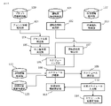
- FIG. 2 is a functional block diagram for explaining the plant operation support system according to the first embodiment. As shown in FIG. 2, this plant operation support system has a plurality of components described below.
- this plant operation support system includes a plant information acquisition unit 101 that acquires plant information, an operator information acquisition unit 102 that acquires operator information, a work information acquisition unit 103 that acquires work information, and a plant information acquisition unit 103 that acquires work information.
- a plant status identification unit 104 that identifies the situation, a response priority determination unit 105 that determines the response priority of a plurality of units, a scheduling unit 106 that creates schedule candidates from the determined unit response priority, the operator information and the
- An operator condition identification unit 107 that identifies the operator condition from work information, a schedule evaluation unit 108 that evaluates schedule candidates from the identified operator condition, and a schedule presentation unit that presents the schedule according to the evaluation results of the evaluated schedule. 109.
- Whether or not to add an operator is determined in accordance with the operator addition necessity determination rule stored in the addition necessity determination rule storage unit storing the determination rule for whether or not to add an operator.
- a determination unit 110 and an operator calling unit 111 for calling a necessary operator according to the output of this operator addition necessity determination unit are provided.
- the plant information acquisition unit 101 the operator information acquisition unit 102, the work information acquisition unit 103, the plant status identification unit 104, the response priority determination unit 105, the scheduling unit 106, and the operator status identification unit, which are the above components.
- the processor 1 shown in FIG. to perform their respective functions.
- the processor 1, the memory 2, and the hard disk 3 are shown as an example, but the present invention is not limited to this.
- the hard disk 3 may work together to realize the above function.
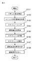
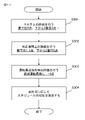
- FIG. 3 is a flow chart showing the operation of the plant operation support system according to the first embodiment.
- the plant status and operator status are specified from the plant information, operator information, and work information, and the optimum operator response procedure for implementation is specified. Assign dynamically according to the situation and operator status, determine whether or not to add an operator, output the schedule result to an external output device such as a monitor or speaker, and call an additional operator. Operation will be explained.
- plant 1 may be referred to as UNIT 1
- plant 2 as UNIT 2
- plant 3 as UNIT 3
- plant 4 as UNIT 4.
- the plant information acquisition unit 101 acquires plant information stored in the plant information storage unit 120 .
- the plant information stored in the plant information storage unit includes static information such as event information (specific examples will be described later) and dynamic information such as plant parameters acquired by each plant device or operation history.
- Plant parameters include operating conditions, including alarms for various plant equipment, or process values.
- plant equipment is equipment that constitutes a plant, and includes, for example, motors, pumps, and valves, although it varies depending on the type of plant. Normally, plant information is prepared for each plant.
- FIG. 4 is an example of event information, which is one of the plant information acquired by the plant information acquisition unit in this embodiment.
- the event information 200 includes the degree of impact 201 for each event, probability of occurrence 202, work procedure 203, response time 204, remaining time 205 (remaining time at the time of event occurrence), and the like.
- the operator information acquisition unit 102 acquires operator information stored in the operator information storage unit 121 .
- the operator information stored in the operator information storage unit 121 includes static information such as the operator's qualification or personality, and dynamic information such as the operator's condition or biological information.
- FIG. 5 shows an example of operator information acquired by the operator information acquisition unit according to the present embodiment.
- the operator information 300 includes qualifications 301 that are qualification information possessed by each operator, skill level 302 of each operator, and work status indicating the work status of each operator, such as operating or waiting. 303, etc.
- the work information acquisition unit 103 acquires work information stored in the work information storage unit 122 .
- the work information stored in the work information storage unit 122 includes details of work procedures, difficulty of work, and the like.
- FIG. 6 is an example of work information acquired by the work information acquisition unit according to the present embodiment.
- the work information 400 includes a work name 401, procedure structure 402, and required qualifications 403 for each work.
- the plant status identification unit 104 identifies the plant status of each plant from the plant information acquired by the plant information acquisition unit 101 (see step S101 in FIG. 3).
- an event occurring in the plant is identified from the above-described alarm information and other plant parameters, and a procedure in progress is identified from the operation history of the plant.
- the occurrence event is specified using knowledge base information that stores data necessary for specifying the event, such as the cause of the event and the relationship that the event affects.
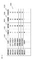
- FIG. 7 shows an example of the plant status identified by the plant status identifying unit 104 in this embodiment.
- the plant status 500 includes an occurrence event 501 for each plant, an occurrence date and time 502, and an ongoing procedure 503.
- FIG. 1 shows an example of the plant status identified by the plant status identifying unit 104 in this embodiment.
- the plant status 500 includes an occurrence event 501 for each plant, an occurrence date and time 502, and an ongoing procedure 503.
- the response priority determination unit 105 determines the response priority of each plant in consideration of the content of the event or progress (see step S102 in FIG. 3).
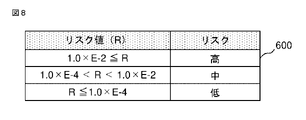
- the response priority is determined based on the evaluation information stored in the evaluation information storage unit 123, the response priority is determined based on the degree of urgency in consideration of the risk of the event occurring in each plant and the margin time for response work.
- the evaluation information storage unit 123 stores information for the response priority determination unit 105 to determine the priority of response to each plant, or information used by the schedule evaluation unit 108 for evaluation.
- the risk of an event can be calculated as the product of the impact of the event and the probability of occurrence. Calculating the risk from the plant information in FIG. 4, event A in plant 2 is 3.0 ⁇ E-2 (E-2 means 10-2. In this case, the impact is 3 and the probability of occurrence is 1/100, and so on), event B for plant 3 is 2.0 ⁇ E ⁇ 4, and event C for plant 4 is 2.0 ⁇ E ⁇ 5.
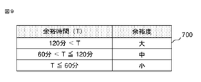
- the margin time of the current response work can be calculated by the difference between the remaining time of the event response and the response time.
- FIG. 8 shows the relationship between the risk value and risk in this embodiment
- FIG. 9 shows the relationship between margin time and margin in this embodiment
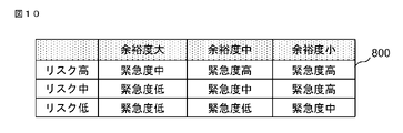
- FIG. 10 shows the relationship between risk, margin and urgency in this embodiment.
- These relational tables are stored in the evaluation information storage unit 123.
- the plant 2 event A has a high risk, a medium margin and a high urgency
- the plant 3 event B has a low risk and a medium margin.
- the urgency level is "low”
- the event C of the plant 4 has a risk of "medium”
- the margin is "medium”
- the urgency level is "medium”. Therefore, the order of priority is determined as plant 2>plant 4>plant 3.
- the risk of an event or the margin time may differ from plant to plant due to differences in system configuration, etc.
- the risk of an event and the margin time plant information and the same.
- the scheduling unit 106 schedules work procedures according to the response priority of each plant output by the response priority determination unit 105, and outputs several work procedure schedule candidates (see step S103 in FIG. 3). .
- the operators currently in operation since it is necessary to respond to a plant with a high degree of urgency as soon as possible, the operators currently in operation (operator A and operator B in this embodiment) will respond as much as possible. schedule.
- procedure 1 (procedure 1-1 to procedure 1-4), which is the work procedure of plant 2 with the highest priority of urgency of "high".
- qualification A is required for performing procedure 1.
- the procedure 1 is assigned to the operator A who has the qualification A.
- Procedure 3 which is the work procedure for plant 4 with the next highest priority of urgency of "medium” (as of 11:00 on December 08, 2020, procedures 3-1 and 3-2 have been completed , in this case, procedures 3-3 to 3-5 are applicable).
- procedure 2 (procedure 2-2 to procedure 2-3 (as of 11:00 on December 08, 2020, procedure 2 -1 is completed, so procedure 2-1 does not apply in this case.)) is assigned.
- the required qualification for performing Procedure 2 is qualification B.
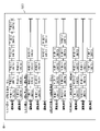
- FIG. 11 shows a total of four schedules, schedule A 900, schedule B 901, schedule C 902, and schedule D 903, which are outputs of the scheduling unit in this embodiment.
- One box representing one task is 30 minutes.
- Operator C and operator E are shown by adding 60 minutes and 90 minutes required for preparation time including movement.
- the operator state identification unit 107 identifies the current operator state based on the operator information or work information (see step S104 in FIG. 3).
- the operator's condition is identified based on operator information such as the operator's degree of fatigue or work load.
- FIG. 12 shows an example of the operator status specified by the operator status specifying unit in this embodiment.
- the operator status 1000 includes a status 1001, a skill level 1002, a fatigue level 1003, an awakening level 1004, and a workload 1005 for each operator. Fatigue, arousal, and workload are measured from biological information such as blood pressure, heart rate, breathing rate, blinking, and electroencephalograms.
- the schedule evaluation unit 108 evaluates the multiple schedules output by the scheduling unit based on the current operator status output by the operator status identification unit (see step S105 in FIG. 3).
- the schedule is evaluated with respect to risk and response time (response time means the time required for an operator to converge the event).
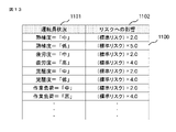
- FIG. 13 shows the relationship between operator states and the effects on risks in this embodiment.
- This relational table 1100 is stored in the evaluation information storage unit 123 .
- the standard risk is corrected according to the effect 1102 on the risk according to the operator status 1101 .
- Operator A who is an operator of plant 2
- Operator B who is an operator of plant 4
- the risks for Plant 3 are calculated for each of Schedules A to D, because the corresponding operators or procedures differ for each schedule.
- Operator B who is an operator of plant 3 of schedule A, has "medium” skill level, "medium” fatigue level, “medium” awakening level, and "low” work load from the operator state 1000 in FIG.
- the sum of the risks of plants 2, 3, and 4 having risks is used as the risk of each schedule.
- the risk evaluation order of schedules is determined by the risk value of plant 3 . From the above discussion, the Schedule A risk value is 1.6 x E-3, the Schedule B risk value is 8.0 x E-4, and the Schedule C risk value is 4.0 x E- 4, Schedule D risk value was 2.0 x E-4. Therefore, the risk evaluation order of the schedules is Schedule D>Schedule C>Schedule B>Schedule A.
- FIG. 11 shows it by adding 60 minutes and 90 minutes required for the preparation time including movement, so the time to complete all the work is the evaluation of the response time. Therefore, the evaluation order of schedules in terms of corresponding time is Schedule C>Schedule A, and Schedule D>Schedule B.
- the schedule presenting unit 109 presents the schedule on an output device such as a monitor based on the evaluation result of the schedule evaluating unit (see step S106 in FIG. 3).
- FIG. 14 shows an example 1200 of presentation by the schedule presentation unit in this embodiment.
- Recommended schedules include schedule B with no additional personnel and the lowest risk value, schedule D with additional personnel and the lowest risk value, schedule A with the shortest response time without additional personnel, and support with additional personnel.
- the schedules corresponding to the four conditions of schedule C, which has the shortest time, are displayed. It should be noted that the implementation may be changeable so as to switch to display in order of risk evaluation or response time, or to switch whether or not to add an operator.
- the operator addition necessity determination unit 110 determines whether it is necessary to add an operator according to the operator excess/deficiency determination rule (see step S107 in FIG. 3).
- FIG. 15 is a flowchart showing an example of addition necessity determination in the present embodiment.
- the addition necessity determination rule used for this addition necessity determination is stored in the addition necessity determination rule storage unit 124 .
- step S201 which is the first processing step, "If an operator is added, is there any rescheduling that improves the risk evaluation compared to when the operator is not added?"
- Schedules C and D which add operators, improve the risk assessment more than Schedules A and B, which do not add operators, so both Schedules C and D are applicable.
- step S202 which is the second processing step, "Is there a schedule that improves the response time when adding an operator compared to not adding an operator?" Although the response time is improved, schedule D is not improved in response time compared to schedule A, so only schedule C is applicable.
- step S203 which is the final processing step, "if multiple schedules apply, determine the schedule that improves the risk assessment the most", since only schedule C is applicable, addition of operator C is required. decide it is necessary.
- the operator calling unit 111 calls the operator according to the determination result of the operator addition necessity determination unit (see step S108 in FIG. 3). In this embodiment, a tablet terminal owned by an additional operator C is notified of an alarm and called.
- the plant situation identifying section and the operator status identifying section identify the current plant or operator status. It is also possible to determine by specifying
- the targets of evaluation are the risk and the response time, but the cost and the like may also be evaluated. Moreover, you may evaluate those evaluation values synthetically. For example, a method of quantifying each element and determining the total numerical value, or a method of weighting each element and calculating the total value can be considered. Furthermore, a method of dynamically changing the weighting is also possible.
- the response priority of the unit (each plant) is determined from the plant status, scheduling is performed based on the response priority of the unit (each plant), and the plant or operator
- scheduling is performed based on the response priority of the unit (each plant)
- the plant or operator By evaluating the schedule based on the situation, it is possible to dynamically assign work to each operator so as to minimize the impact (risk, response time, etc.) of the entire plant, reduce plant operation risks, Efficiency and cost reduction are possible.
- the necessity of adding an operator is determined, and when an operator needs to be added, the optimum operator is specified and called, thereby enabling plant operation. further risk reduction.
- Embodiment 2 The hardware configuration diagram of the second embodiment is the same as the hardware configuration diagram of the first embodiment.
- FIG. 16 is a functional block diagram showing Embodiment 2 of the plant operation support system according to Embodiment 2.
- An evaluation judgment rule storage unit 125, a determination schedule input unit 112, an evaluation judgment rule update unit 113, and a schedule result notification unit 114 are added to the functional blocks of the first embodiment.
- the evaluation judgment rule storage unit 125 stores evaluation judgment rules for evaluating schedules.
- FIG. 17 shows an example of a flowchart used for this schedule evaluation determination. Evaluation judgment rule data stored in the evaluation judgment rule storage unit is used for the evaluation judgment here.
- the schedule evaluation unit 108 evaluates the schedules according to the evaluation determination rule of FIG. 17 and determines the order of the schedules.
- step S301 which is a processing step for evaluation judgment, risk evaluation is performed.
- risk evaluation is performed.
- Schedule A is "1 point”
- Schedule B is “2 points”
- Schedule C is "3 points”.
- schedule D becomes "4 points”.
- step S302 which is a processing step for evaluation judgment, an evaluation is made regarding the response time.
- step S302 an evaluation is made regarding the response time.
- Schedule C>Schedule A, Schedule D>Schedule B" as in Embodiment 1, Schedule A "3.75 points”, Schedule B "1.5 points”, Schedule C "6 points” points” and Schedule D "3.75 points".
- Schedule A and Schedule D have the same score in terms of response time and are second from the bottom. "Dot" is used.
- step S303 which is a processing step for evaluation determination, whether or not an operator is added is evaluated.
- Schedule A and Schedule B which do not have additional operators, are given "+4 points”.
- step S304 which is an evaluation determination processing step, the scores evaluated so far are added to calculate the total score, and the ranking of the schedule is determined according to the total score.
- the schedule presenting unit 109 presents the schedule to an output device such as a monitor based on the evaluation result of the schedule evaluating unit.
- FIG. 18 shows an example 1300 of presentation by the schedule presentation unit according to the second embodiment. "Schedule C", “Schedule A”, and “Schedule D” are displayed according to the evaluation order evaluated by the schedule evaluation unit 108. FIG. In addition to the evaluation ranking, the ranking and evaluation points in terms of response time, the ranking and evaluation points in terms of risk, and the presence or absence of additional operators and evaluation points are displayed together.
- the decision schedule input unit 112 inputs the decision of the schedule by the user.
- the determination schedule input unit displays the schedule and the reason for determination so that they can be selected with check boxes. Select by input. It is assumed that the user, that is, the leader of the operators in this embodiment, selects the second-ranked "Schedule A" and the main reason for the decision "whether or not to add operators" by using the check boxes.
- the evaluation judgment rule update unit 113 updates the evaluation judgment rule according to the input contents of the determination schedule input unit 112.
- the processing step S303 regarding "whether or not an operator is added” is corrected according to the selected main reason for determination "whether or not an operator is added” so that the total score of Schedule A exceeds that of Schedule C. .
- "Evaluate whether or not to add an operator. No additional operator: +4 points” is updated to "Evaluate whether or not to add an operator. No additional operator: +4.5 points.”
- the schedule evaluation unit 108 evaluates the schedule according to the updated evaluation determination rule.
- the schedule result notification unit 114 notifies each operator of the schedule results according to the input contents of the determined schedule input unit 112 .
- an alarm is notified to a tablet terminal owned by each operator.
- FIG. 19 is an example 1400 of result notification by the schedule result notification unit in the second embodiment.
- the well-known example 1400 notifies the operator A of the change of the operating procedure. It shows that the procedure 1402 before change has been changed to the procedure 1401 after change. Changes in procedures are indicated in red.
- the evaluation determination rule updating unit uses a simple method to update the evaluation determination rule. You can use artificial intelligence.
Landscapes
- Business, Economics & Management (AREA)
- Human Resources & Organizations (AREA)
- Engineering & Computer Science (AREA)
- Strategic Management (AREA)
- Economics (AREA)
- Entrepreneurship & Innovation (AREA)
- Educational Administration (AREA)
- General Physics & Mathematics (AREA)
- Quality & Reliability (AREA)
- Development Economics (AREA)
- Physics & Mathematics (AREA)
- General Business, Economics & Management (AREA)
- Tourism & Hospitality (AREA)
- Operations Research (AREA)
- Game Theory and Decision Science (AREA)
- Marketing (AREA)
- Theoretical Computer Science (AREA)
- General Engineering & Computer Science (AREA)
- Manufacturing & Machinery (AREA)
- Automation & Control Theory (AREA)
- Management, Administration, Business Operations System, And Electronic Commerce (AREA)
- Testing And Monitoring For Control Systems (AREA)
- General Factory Administration (AREA)
Priority Applications (4)
| Application Number | Priority Date | Filing Date | Title |
|---|---|---|---|
| PCT/JP2021/007267 WO2022180768A1 (ja) | 2021-02-26 | 2021-02-26 | プラント運転支援システム |
| JP2023501940A JP7412630B2 (ja) | 2021-02-26 | 2021-02-26 | プラント運転支援システム |
| CA3204581A CA3204581C (en) | 2021-02-26 | 2021-02-26 | INSTALLATION OPERATIONAL ASSISTANCE SYSTEM |
| US18/258,364 US20240037466A1 (en) | 2021-02-26 | 2021-02-26 | Plant operation assistance system |
Applications Claiming Priority (1)
| Application Number | Priority Date | Filing Date | Title |
|---|---|---|---|
| PCT/JP2021/007267 WO2022180768A1 (ja) | 2021-02-26 | 2021-02-26 | プラント運転支援システム |
Publications (1)
| Publication Number | Publication Date |
|---|---|
| WO2022180768A1 true WO2022180768A1 (ja) | 2022-09-01 |
Family
ID=83048932
Family Applications (1)
| Application Number | Title | Priority Date | Filing Date |
|---|---|---|---|
| PCT/JP2021/007267 Ceased WO2022180768A1 (ja) | 2021-02-26 | 2021-02-26 | プラント運転支援システム |
Country Status (4)
| Country | Link |
|---|---|
| US (1) | US20240037466A1 (https=) |
| JP (1) | JP7412630B2 (https=) |
| CA (1) | CA3204581C (https=) |
| WO (1) | WO2022180768A1 (https=) |
Cited By (1)
| Publication number | Priority date | Publication date | Assignee | Title |
|---|---|---|---|---|
| WO2025046737A1 (ja) * | 2023-08-29 | 2025-03-06 | 三菱電機株式会社 | プラント設計支援システム、および、プラント設計支援方法 |
Citations (2)
| Publication number | Priority date | Publication date | Assignee | Title |
|---|---|---|---|---|
| JP2006252311A (ja) * | 2005-03-11 | 2006-09-21 | Toshiba Corp | 設備保全計画支援システムおよびその支援方法 |
| JP2017010320A (ja) * | 2015-06-23 | 2017-01-12 | 株式会社東芝 | リソース管理システム、及びリソース管理方法 |
-
2021
- 2021-02-26 CA CA3204581A patent/CA3204581C/en active Active
- 2021-02-26 WO PCT/JP2021/007267 patent/WO2022180768A1/ja not_active Ceased
- 2021-02-26 US US18/258,364 patent/US20240037466A1/en active Pending
- 2021-02-26 JP JP2023501940A patent/JP7412630B2/ja active Active
Patent Citations (2)
| Publication number | Priority date | Publication date | Assignee | Title |
|---|---|---|---|---|
| JP2006252311A (ja) * | 2005-03-11 | 2006-09-21 | Toshiba Corp | 設備保全計画支援システムおよびその支援方法 |
| JP2017010320A (ja) * | 2015-06-23 | 2017-01-12 | 株式会社東芝 | リソース管理システム、及びリソース管理方法 |
Cited By (1)
| Publication number | Priority date | Publication date | Assignee | Title |
|---|---|---|---|---|
| WO2025046737A1 (ja) * | 2023-08-29 | 2025-03-06 | 三菱電機株式会社 | プラント設計支援システム、および、プラント設計支援方法 |
Also Published As
| Publication number | Publication date |
|---|---|
| US20240037466A1 (en) | 2024-02-01 |
| JPWO2022180768A1 (https=) | 2022-09-01 |
| CA3204581A1 (en) | 2022-09-01 |
| JP7412630B2 (ja) | 2024-01-12 |
| CA3204581C (en) | 2025-05-06 |
Similar Documents
| Publication | Publication Date | Title |
|---|---|---|
| CN105095056B (zh) | 一种数据仓库数据监控的方法 | |
| JP5223413B2 (ja) | Itシステムのトラブル対処装置、トラブル対処方法およびそのためのプログラム | |
| US8698616B2 (en) | Monitor control system | |
| CN106411609A (zh) | 一种it软硬件运行状态监控系统 | |
| US20210216972A1 (en) | System and Method for Managing Events | |
| JP2018120456A (ja) | アラーム表示システムおよびアラーム表示方法 | |
| US20080162396A1 (en) | Transaction Data Processing System | |
| AU2020360426A1 (en) | Enhancing patient care via a structured methodology for workflow stratification | |
| WO2022180768A1 (ja) | プラント運転支援システム | |
| US20210097459A1 (en) | Worker assignment system and worker assignment device | |
| JP2019061500A (ja) | 予兆診断システム | |
| JP5336850B2 (ja) | プロセス産業プラントの安全性評価のためのコンピュータ・システムおよびコンピュータ・ベースの方法 | |
| US20220156672A1 (en) | Information processing apparatus and method | |
| JP7186924B2 (ja) | 作業割当て装置 | |
| US11244260B1 (en) | Monitoring and creating customized dynamic project files based on enterprise resources | |
| US11501226B1 (en) | Monitoring and creating customized dynamic project files based on enterprise resources | |
| CN114781888A (zh) | 一种机器生产数据的处理方法、装置、设备及存储介质 | |
| JP7778233B2 (ja) | プラント運転支援システム | |
| JP7055939B1 (ja) | 工程管理装置および工程管理プログラム | |
| EP4553598A1 (en) | Artificial intelligence model to analyze process alarms and generate corresponding rationalization actions | |
| US20250094895A1 (en) | Systems and methods for trading shift of unavailable preference using trade queues | |
| JP2025086617A (ja) | 技量管理システム | |
| JP2013117754A (ja) | リスク評価装置及びリスク評価プログラム | |
| JP2024164382A (ja) | 異常対処システムおよび異常対処方法 | |
| US11934986B2 (en) | Plant operation support apparatus and plant operation support method |
Legal Events
| Date | Code | Title | Description |
|---|---|---|---|
| 121 | Ep: the epo has been informed by wipo that ep was designated in this application |
Ref document number: 21927870 Country of ref document: EP Kind code of ref document: A1 |
|
| ENP | Entry into the national phase |
Ref document number: 2023501940 Country of ref document: JP Kind code of ref document: A |
|
| WWE | Wipo information: entry into national phase |
Ref document number: 18258364 Country of ref document: US |
|
| ENP | Entry into the national phase |
Ref document number: 3204581 Country of ref document: CA |
|
| NENP | Non-entry into the national phase |
Ref country code: DE |
|
| 122 | Ep: pct application non-entry in european phase |
Ref document number: 21927870 Country of ref document: EP Kind code of ref document: A1 |