WO2022176621A1 - 撮像システム、および撮像システムによって実行される方法 - Google Patents
撮像システム、および撮像システムによって実行される方法 Download PDFInfo
- Publication number
- WO2022176621A1 WO2022176621A1 PCT/JP2022/004003 JP2022004003W WO2022176621A1 WO 2022176621 A1 WO2022176621 A1 WO 2022176621A1 JP 2022004003 W JP2022004003 W JP 2022004003W WO 2022176621 A1 WO2022176621 A1 WO 2022176621A1
- Authority
- WO
- WIPO (PCT)
- Prior art keywords
- image data
- light
- imaging system
- image
- data
- Prior art date
- Legal status (The legal status is an assumption and is not a legal conclusion. Google has not performed a legal analysis and makes no representation as to the accuracy of the status listed.)
- Ceased
Links
Images


Classifications
-
- H—ELECTRICITY
- H04—ELECTRIC COMMUNICATION TECHNIQUE
- H04N—PICTORIAL COMMUNICATION, e.g. TELEVISION
- H04N23/00—Cameras or camera modules comprising electronic image sensors; Control thereof
- H04N23/10—Cameras or camera modules comprising electronic image sensors; Control thereof for generating image signals from different wavelengths
-
- G—PHYSICS
- G01—MEASURING; TESTING
- G01J—MEASUREMENT OF INTENSITY, VELOCITY, SPECTRAL CONTENT, POLARISATION, PHASE OR PULSE CHARACTERISTICS OF INFRARED, VISIBLE OR ULTRAVIOLET LIGHT; COLORIMETRY; RADIATION PYROMETRY
- G01J3/00—Spectrometry; Spectrophotometry; Monochromators; Measuring colours
- G01J3/12—Generating the spectrum; Monochromators
-
- G—PHYSICS
- G01—MEASURING; TESTING
- G01J—MEASUREMENT OF INTENSITY, VELOCITY, SPECTRAL CONTENT, POLARISATION, PHASE OR PULSE CHARACTERISTICS OF INFRARED, VISIBLE OR ULTRAVIOLET LIGHT; COLORIMETRY; RADIATION PYROMETRY
- G01J3/00—Spectrometry; Spectrophotometry; Monochromators; Measuring colours
- G01J3/28—Investigating the spectrum
- G01J3/2823—Imaging spectrometer
-
- G—PHYSICS
- G06—COMPUTING OR CALCULATING; COUNTING
- G06T—IMAGE DATA PROCESSING OR GENERATION, IN GENERAL
- G06T7/00—Image analysis
- G06T7/80—Analysis of captured images to determine intrinsic or extrinsic camera parameters, i.e. camera calibration
-
- H—ELECTRICITY
- H04—ELECTRIC COMMUNICATION TECHNIQUE
- H04N—PICTORIAL COMMUNICATION, e.g. TELEVISION
- H04N23/00—Cameras or camera modules comprising electronic image sensors; Control thereof
- H04N23/10—Cameras or camera modules comprising electronic image sensors; Control thereof for generating image signals from different wavelengths
- H04N23/12—Cameras or camera modules comprising electronic image sensors; Control thereof for generating image signals from different wavelengths with one sensor only
-
- G—PHYSICS
- G01—MEASURING; TESTING
- G01J—MEASUREMENT OF INTENSITY, VELOCITY, SPECTRAL CONTENT, POLARISATION, PHASE OR PULSE CHARACTERISTICS OF INFRARED, VISIBLE OR ULTRAVIOLET LIGHT; COLORIMETRY; RADIATION PYROMETRY
- G01J3/00—Spectrometry; Spectrophotometry; Monochromators; Measuring colours
- G01J3/12—Generating the spectrum; Monochromators
- G01J2003/1213—Filters in general, e.g. dichroic, band
- G01J2003/1217—Indexed discrete filters or choppers
-
- G—PHYSICS
- G01—MEASURING; TESTING
- G01J—MEASUREMENT OF INTENSITY, VELOCITY, SPECTRAL CONTENT, POLARISATION, PHASE OR PULSE CHARACTERISTICS OF INFRARED, VISIBLE OR ULTRAVIOLET LIGHT; COLORIMETRY; RADIATION PYROMETRY
- G01J3/00—Spectrometry; Spectrophotometry; Monochromators; Measuring colours
- G01J3/28—Investigating the spectrum
- G01J3/2823—Imaging spectrometer
- G01J2003/2826—Multispectral imaging, e.g. filter imaging
-
- G—PHYSICS
- G06—COMPUTING OR CALCULATING; COUNTING
- G06T—IMAGE DATA PROCESSING OR GENERATION, IN GENERAL
- G06T2200/00—Indexing scheme for image data processing or generation, in general
- G06T2200/24—Indexing scheme for image data processing or generation, in general involving graphical user interfaces [GUIs]
Definitions
- the present disclosure relates to imaging systems and methods performed by imaging systems.
- a hyperspectral camera can obtain more wavelength information about an object than a general RBG camera. Based on the hyperspectral image of the object captured by the hyperspectral camera, the spectral properties of the object can be accurately analyzed.
- Hyperspectral cameras are expected to be used in a variety of applications such as analysis, research, and product inspection. There are two types of hyperspectral cameras: a system using a spectral element such as a prism or a grating, and a system using a compression sensing technique disclosed in Japanese Unexamined Patent Application Publication No. 2002-200012.
- Patent Literature 2 discloses an example of calibration of a spectroscopic device using spectroscopic elements.
- the present disclosure provides an imaging system that facilitates calibration of imaging devices that employ compressed sensing techniques.
- An imaging system is an imaging system that uses compression sensing technology, and includes a filter array including a plurality of types of filters having different transmission spectra, and image data based on light passing through the filter array.
- a processing circuit that generates hyperspectral image data including a light source that emits reference light having a wavelength of at least one of the four or more bands, which is used for calibration for correcting the reconstruction table; wherein the processing circuit corrects the restoration table based on reference image data generated by the image sensor detecting the reference light.
- Computer-readable recording media include non-volatile recording media such as CD-ROMs (Compact Disc-Read Only Memory).
- a device may consist of one or more devices. When the device is composed of two or more devices, the two or more devices may be arranged in one device, or may be divided and arranged in two or more separate devices. As used herein and in the claims, a "device” can mean not only one device, but also a system of multiple devices. A plurality of devices included in the "system” may include devices installed remotely from other devices and connected via a communication network.
- FIG. 1A is a diagram for explaining the relationship between a target wavelength range and multiple bands included therein.
- FIG. 1B is a diagram schematically showing an example of a hyperspectral image.
- FIG. 2A is a diagram schematically showing an example of a filter array.
- 2B is a diagram showing an example of a transmission spectrum of a first filter included in the filter array shown in FIG. 2A;
- FIG. 2C is a diagram showing an example of a transmission spectrum of a second filter included in the filter array shown in FIG. 2A;
- FIG. 2D is a diagram showing an example of the spatial distribution of the light transmittance of each of a plurality of bands W 1 , W 2 , . . . , W i included in the target wavelength range.
- FIG. 1A is a diagram for explaining the relationship between a target wavelength range and multiple bands included therein.
- FIG. 1B is a diagram schematically showing an example of a hyperspectral image.
- FIG. 2A is a
- FIG. 3 is a block diagram that schematically illustrates the configuration of an imaging system according to an exemplary embodiment of the present disclosure
- FIG. 4A is a diagram schematically showing a first example of a spectrum of reference light emitted from a light source
- FIG. 4B is a diagram schematically showing a second example of the spectrum of the reference light emitted from the light source
- FIG. 5 is a flow chart showing an example of operations performed by the processing circuit during imaging.
- FIG. 6 is a flow chart showing an example of calibration operation for correcting the restoration table.
- FIG. 7A is a diagram illustrating a first example of data stored in a storage device
- FIG. 7B is a diagram illustrating a second example of data stored in the storage device;
- FIG. 7C is a diagram illustrating a third example of data stored in the storage device
- FIG. 8A is a diagram schematically showing a first example of a GUI displayed on a display device
- FIG. 8B is a diagram schematically showing a second example of the GUI displayed on the display device.
- FIG. 9A is a perspective view schematically showing an example of the appearance shape of the imaging system. 9B is a perspective view when the light source shown in FIG. 9A is viewed from the light exit surface side.
- FIG. 10A is a diagram schematically showing an example of an imaging system according to Modification 1 of the embodiment of the present disclosure.
- FIG. 10B is a diagram schematically illustrating an example of an imaging system according to Modification 2 of the embodiment of the present disclosure;
- FIG. 1 is a diagram schematically showing a first example of a GUI displayed on a display device
- FIG. 8B is a diagram schematically showing a second example of the GUI displayed on the display device.
- FIG. 9A is a perspective view
- FIG. 11A is a diagram showing the first image and the image data g1 expressed in a matrix format.
- FIG. 11B is a diagram showing the image Im11 and the image data f21 expressed in a matrix format.
- FIG. 11C is a diagram showing an image Im22 and image data f22 expressed in a matrix format.
- FIG. 11D is a diagram showing an image Im23 and image data f23 expressed in a matrix format.
- FIG. 11E is a diagram showing an image Im24 and image data f24 expressed in a matrix format.
- FIG. 12 is a diagram showing spectrum data of the third light.
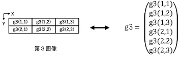
- FIG. 13A is a diagram showing the third image and the image data g3 expressed in a matrix format.
- FIG. 13B is a diagram showing an image Im41 and image data f41 expressed in a matrix format.
- FIG. 13C is a diagram showing an image Im42 and image data f42 expressed in a matrix format.
- FIG. 13D is a diagram showing an image Im43 and image data f43 expressed in a matrix format.
- FIG. 13E is a diagram showing an image Im44 and image data f44 expressed in a matrix format.
- FIG. 14A is a diagram showing the fifth image and the image data g5 expressed in a matrix format.
- FIG. 14B is a diagram showing image Im61 and image data f61 expressed in a matrix format.
- FIG. 14C is a diagram showing an image Im62 and image data f62 expressed in a matrix format.
- FIG. 14D is a diagram showing an image Im63 and image data f63 expressed in a matrix format.
- FIG. 14E is a diagram showing the image Im64 and the image data f64 expressed in a matrix format.
- all or part of a circuit, unit, device, member or section, or all or part of a functional block in a block diagram is, for example, a semiconductor device, a semiconductor integrated circuit (IC), or an LSI (large scale integration). ) may be performed by one or more electronic circuits.
- An LSI or IC may be integrated on one chip, or may be configured by combining a plurality of chips.
- functional blocks other than memory elements may be integrated into one chip.
- LSIs or ICs may be called system LSIs, VLSIs (very large scale integration), or ULSIs (ultra large scale integration) depending on the degree of integration.
- a Field Programmable Gate Array (FPGA), which is programmed after the LSI is manufactured, or a reconfigurable logic device that can reconfigure the connection relationships inside the LSI or set up the circuit partitions inside the LSI can also be used for the same purpose.
- FPGA Field Programmable Gate Array
- circuits, units, devices, members or parts can be executed by software processing.
- the software is recorded on one or more non-transitory storage media, such as ROMs, optical discs, hard disk drives, etc., such that when the software is executed by a processor, the functions specified in the software are performed. It is executed by processors and peripherals.
- a system or apparatus may include one or more non-transitory storage media on which software is recorded, a processor, and required hardware devices such as interfaces.
- a hyperspectral image is image data that has more wavelength information than a typical RGB image.
- An RGB image has values for each of three bands, red (R), green (G), and blue (B), for each pixel.
- a hyperspectral image has values for more bands per pixel than the number of bands in an RGB image.
- "hyperspectral image” means image data that includes a plurality of images corresponding to each of four or more bands contained in a predetermined wavelength range of interest.
- a value that each pixel has for each band is referred to as a "pixel value" in the following description.
- the number of bands in a hyperspectral image is typically 10 or more, and may exceed 100 in some cases.
- a "hyperspectral image” is sometimes referred to as a “hyperspectral datacube” or “hyperspectral cube.”
- FIG. 1A is a diagram for explaining the relationship between a target wavelength band W and a plurality of bands W 1 , W 2 , . . . , W i included therein.
- the target wavelength band W can be set in various ranges depending on the application.
- the target wavelength range W can be, for example, a visible light wavelength range from about 400 nm to about 700 nm, a near-infrared wavelength range from about 700 nm to about 2500 nm, or a near-ultraviolet wavelength range from about 10 nm to about 400 nm.
- the target wavelength range W may be a mid-infrared or far-infrared wavelength range.
- the wavelength range used is not limited to the visible light range. In this specification, not only visible light but also electromagnetic waves with wavelengths outside the visible light wavelength range, such as ultraviolet rays and near-infrared rays, are referred to as "light" for convenience.
- i is an arbitrary integer equal to or greater than 4, and the respective wavelength ranges obtained by equally dividing the target wavelength range W into i are defined as bands W 1 , W 2 , . . . , W i .
- a plurality of bands included in the target wavelength band W may be set arbitrarily.
- the bands may have uneven widths. There may be gaps between adjacent bands. If the number of bands is four or more, more information can be obtained from the hyperspectral image than from the RGB image.
- FIG. 1B is a diagram schematically showing an example of the hyperspectral image 22.
- the imaging target is an apple.
- Hyperspectral image 22 includes image 22W 1 for band W 1 , image 22W 2 for band W 2 , . . . , image 22W i for band W i .
- Each of these images includes a plurality of pixels arranged two-dimensionally.
- FIG. 1B exemplifies vertical and horizontal dashed lines indicating divisions of pixels.
- the actual number of pixels per image can be a large value, such as tens of thousands to tens of millions, but in FIG.
- each photodetector element in the image sensor It is Reflected light generated when an object is irradiated with light is detected by each photodetector element in the image sensor.
- a signal indicating the amount of light detected by each photodetector represents the pixel value of the pixel corresponding to that photodetector.
- Each pixel in the hyperspectral image 22 has a pixel value for each band. Therefore, by acquiring the hyperspectral image 22, it is possible to obtain information on the two-dimensional distribution of the spectrum of the object. Based on the spectrum of the object, the optical properties of the object can be accurately analyzed.
- the hyperspectral image data includes a plurality of pixel values of a plurality of pixels included in the image 22W1 , a plurality of pixel values of a plurality of pixels included in the image 22W2 , . It may be a plurality of pixel values, or information indicating the reflectance of the subject obtained by standardizing the plurality of pixel values.
- a hyperspectral image can be acquired by imaging using a spectroscopic element such as a prism or grating, for example.
- a spectroscopic element such as a prism or grating
- the light is emitted from the emission surface of the prism at an emission angle corresponding to the wavelength.
- a grating when reflected light or transmitted light from an object enters the grating, the light is diffracted at a diffraction angle according to the wavelength.
- a hyperspectral image can be obtained by splitting the light from the object into bands using a prism or grating and detecting the separated light for each band.
- a hyperspectral image can also be obtained using the compressed sensing technique disclosed in Patent Document 1.
- an image sensor detects light reflected from an object through a filter array called an encoding element or an encoding mask.
- the filter array includes a plurality of filters arranged two-dimensionally. Each of these filters has a unique transmission spectrum. Imaging using such a filter array yields a compressed image in which image information of a plurality of bands is compressed as one two-dimensional image.
- the spectral information of the object is compressed and recorded as one pixel value for each pixel.
- each pixel contained in the compressed image contains information corresponding to multiple bands.
- FIG. 2A is a diagram schematically showing an example of the filter array 10.
- the filter array 10 includes a plurality of filters arranged two-dimensionally. Each filter has an individually set transmission spectrum.
- the transmission spectrum is represented by a function T( ⁇ ), where ⁇ is the wavelength of incident light.
- the transmission spectrum T( ⁇ ) can take a value of 0 or more and 1 or less.
- the filter array 10 has 48 rectangular filters arranged in 6 rows and 8 columns. This is only an example and in actual applications more filters may be provided.
- the number of filters included in the filter array 10 may be approximately the same as the number of pixels of the image sensor.
- 2B and 2C are diagrams showing examples of transmission spectra of the first filter A1 and the second filter A2, respectively, among the plurality of filters included in the filter array 10 of FIG. 2A.
- the transmission spectrum of the first filter A1 and the transmission spectrum of the second filter A2 are different from each other.
- the transmission spectrum of the filter array 10 differs depending on the filters. However, it is not necessary that all filters have different transmission spectra.
- the filter array 10 includes multiple types of filters with different transmission spectra.
- the number of transmission spectrum patterns of the plurality of types of filters included in the filter array 10 can be equal to or greater than the number i of bands included in the target wavelength band.
- Filter array 10 may be designed such that more than half of the filters have different transmission spectra.
- FIG. 2D is a diagram showing an example of the spatial distribution of the light transmittance of each of a plurality of bands W 1 , W 2 , . . . , W i included in the target wavelength range.
- the difference in shade of each filter represents the difference in light transmittance.
- a lighter filter has a higher transmittance, and a darker filter has a lower transmittance.
- the spatial distribution of light transmittance differs depending on the band.
- the data representing the spatial distribution of light transmittance for each band in the filter array is referred to as a "restoration table".
- Compressed sensing techniques can reconstruct hyperspectral images from compressed images using reconstruction tables.
- compressed sensing techniques do not require the use of prisms or gratings, hyperspectral cameras can be made smaller. Furthermore, compressed sensing techniques can reduce the amount of data processed by the processing circuitry by compressing multiple spectral information into a single compressed image. Details of how to obtain hyperspectral images by compressed sensing techniques are disclosed in US Pat. The entire disclosure of Patent Document 1 is incorporated herein by reference.
- a restoration table corresponding to the filter array 10 is defined as a matrix by calibration before imaging.
- the accuracy of the reconstruction table has a great influence on the accuracy of the actual reconstructed image. Therefore, it is required to calibrate the restoration table accurately. For this reason, hyperspectral cameras are shipped after generating an accurate reconstruction table through careful calibration at the time of manufacture.
- a reconstruction table can be obtained, for example, in a tightly temperature-controlled optical chamber using a tunable laser source and an integrating sphere as follows.
- the wavelength tunable laser light source emits light with a wavelength corresponding to any one band included in the target wavelength range. By inputting the light emitted from the wavelength tunable laser light source into the integrating sphere and diffusing and reflecting the light, planarly uniform light is generated.
- the planarly uniform light is detected by the image sensor through the filter array 10 .
- a reconstruction table is generated by performing the above operations for all bands included in the target wavelength band. If the wavelength range of interest includes 10 bands, 10 photodetections are performed in the calibration of the reconstruction table.
- the restoration accuracy of the hyperspectral image will deteriorate. decreases.
- the deviation of the restoration table is defined by how much each element of the matrix constituting the restoration table acquired at the time of manufacture differs from the actual light transmittance of the filter array 10 . If there is a deviation in the reconstruction table, the user typically sends the hyperspectral camera back to the manufacturer. The manufacturer performs the above calibration again and creates a new restoration table. It is time consuming and costly to send the hyperspectral camera back to the manufacturer each time the reconstruction table drifts.
- the hyperspectral camera can be used stably in the long term.
- an imaging system that allows the user to easily calibrate the reconstruction table on site.
- Patent Document 2 discloses a method of calibrating a spectroscopic device at a work site. In this calibration, the wavelength deviation of the spectral profile obtained by the spectroscopic device is corrected.
- the system used for calibration includes an integrating sphere, a white plate, and a grating in addition to the xenon lamp and sensor array.
- the integrating sphere diffusely reflects and homogenizes the light emitted from the xenon lamp.
- a white plate is attached to the aperture of the integrating sphere and reflects the light homogenized within the integrating sphere.
- the grating separates the light reflected by the white plate into bands and makes the light incident on each pixel of the sensor array.
- a spectral profile is obtained from the intensity of light incident on each pixel of the sensor array for each band.
- the deviation of the wavelength of the spectral profile obtained by the spectroscopic device is corrected.
- the system does not correct for deviations in the reconstruction table used in compressed sensing techniques.
- the system is still bulky with the integrating sphere and grating.
- An imaging system includes an imaging device that employs compression sensing technology and a light source that emits reference light used for calibration to correct a reconstruction table.
- the imaging system according to this embodiment does not require a grating for band spectroscopy and an integrating sphere that diffusely reflects and homogenizes light, so it is compact and inexpensive.
- the imaging system according to this embodiment does not require strict temperature control.
- the user can easily perform calibration for correcting the restoration table under the actual usage environment. Imaging systems and methods performed by imaging systems according to embodiments of the present disclosure are described below.
- An imaging system is an imaging system using compression sensing technology, which generates image data based on a filter array including a plurality of types of filters having different transmission spectra, and light passing through the filter array.
- a processing circuit that generates hyperspectral image data including: Prepare. The processing circuit corrects the reconstruction table based on reference image data generated by the image sensor detecting the reference light.
- This imaging system facilitates the calibration of imaging devices that use compressed sensing technology.
- the imaging system according to the second item is the imaging system according to the first item, further comprising a storage device for storing spectral data of the reference light.
- the processing circuit generates reference restored image data based on the restoration table and the reference image data, and corrects the restoration table based on the spectral data stored in the storage device and the reference restored image data. do.
- the restoration table can be easily corrected based on the spectral data of the reference light and the reference restoration image data.
- the imaging system according to the third item is the imaging system according to the second item, wherein the processing circuit stores the corrected restoration table in the storage device.
- An imaging system is the imaging system according to any one of the first to third items, wherein the processing circuit converts information about the usage status of the imaging system before correction to the corrected restoration table. and stored in the storage device.
- the post-correction restoration table associated with the above information can be used as a use case.
- the imaging system according to the fifth item is the imaging system according to any one of the first to fourth items, wherein the reference light has wavelengths in at least two bands among the four or more bands.
- the imaging system according to the sixth item is the imaging system according to any one of the first to fifth items, wherein the reference light has all wavelengths of the four or more bands.
- the imaging system according to the seventh item is the imaging system according to the fifth or sixth item, wherein the reference image data includes data of a plurality of pixels. Data for each of the plurality of pixels includes information corresponding to wavelengths of two or more bands of the reference light.
- the reference image data is compressed image data.
- An imaging system is the imaging system according to any one of the first to seventh items, wherein the number of the bands included in the target wavelength range in the calibration is less than the number of the bands included in the image sensor.
- the reference image data is generated by detecting the reference light a number of times.
- the reference image data can be efficiently generated by detecting the reference light a smaller number of times than the number of bands included in the target wavelength range.
- the imaging system according to the ninth item is the imaging system according to any one of the first to eighth items, wherein the light source is a surface light source having a light exit surface.
- the image sensor generates the reference image data by imaging the light exit surface through the filter array.
- the photodetection surface of the image sensor can be uniformly illuminated with reference light.
- An imaging system is the imaging system according to any one of the first to ninth items, wherein the processing circuit causes a display device to display a GUI for a user to instruct the start of the calibration. .
- calibration can be started according to user instructions via the GUI.
- the imaging system according to the eleventh item is the imaging system according to the tenth item, wherein the processing circuit causes a display device to display a GUI for inputting information about the usage status of the imaging system before the calibration. .
- correction data with the same or similar usage conditions can be read from past correction data.
- the imaging system according to the twelfth item is the imaging system according to any one of the first to eleventh items, wherein the reference image data is emitted from the light source toward a reference object and reflected by the reference object. It is generated by the image sensor detecting the reference light.
- reference light can be detected through a reference object to generate reference image data.
- the imaging system according to the thirteenth item is the imaging system according to any one of the first to twelfth items, wherein the correction of the restoration table causes the deviation of the element corresponding to the transmission spectrum included in the restoration table. including correcting
- An imaging system is an imaging system using compressed sensing technology, wherein image data is generated by a filter array including a plurality of types of filters having mutually different transmission spectra, and imaging through the filter array.
- a storage device for storing spectral data for the reference object. The processing circuit corrects the reconstruction table based on reference image data generated by imaging the reference object whose spectral data is stored in the storage device.
- the restoration table can be corrected based on the reference data generated by detecting the light generated by the ambient light reflected by the reference object.
- the method according to the fifteenth item is a computer-implemented method of processing data related to the technique of compressed sensing.
- an image sensor that generates image data based on light passing through a filter array including a plurality of types of filters with different transmission spectra is at least one of four or more bands included in the target wavelength range.
- obtaining reference image data generated by detecting reference light having a band of wavelengths obtaining a reconstruction table determined based on the spatial distribution of the transmission spectra of the plurality of types of filters; and calibrating the reconstruction table based on reference image data.
- This method facilitates the calibration of imaging devices that use compressed sensing techniques.
- the method according to the sixteenth item is the method according to the fifteenth item, comprising obtaining spectral data of the reference light and generating reference restored image data based on the restoration table and the reference image data. and correcting the reconstruction table based on the spectral data and the reference reconstructed image data.
- the restoration table can be easily corrected based on the spectral data of the reference light and the reference restored image data.
- the method according to the seventeenth item, in the method according to the sixteenth item, further includes storing the corrected restoration table in a storage device.
- the hyperspectral image data of the object can be generated more accurately based on the stored corrected restoration table.
- FIG. 3 is a block diagram that schematically illustrates the configuration of an imaging system according to an exemplary embodiment of the present disclosure
- An imaging system 200 shown in FIG. 3 includes an imaging device 100 and a light source 70 .
- the imaging device 100 includes a filter array 10 , an image sensor 20 , an optical system 30 , a storage device 40 , a display device 50 , a processing circuit 60 and a memory 62 .
- the imaging device 100 functions as a hyperspectral camera.
- the imaging device 100 shown in FIG. 3 may be part of the configuration of, for example, a mobile terminal or a personal computer.
- the filter array 10 has a light incident surface 10s.
- the filter array 10 modulates the intensity of the light incident on the light incident surface 10s for each filter and emits the light. Details of the filter array 10 are as described above.
- the image sensor 20 has a photodetection surface 20s and includes a plurality of photodetection elements arranged two-dimensionally along the photodetection surface 20s.
- the width of the light detection surface 20s of the image sensor 20 is approximately equal to the width of the light incident surface 10s of the filter array 10.
- FIG. The image sensor 20 is arranged at a position that receives light that has passed through the filter array 10 .
- a plurality of photodetecting elements included in the image sensor 20 correspond to a plurality of filters included in the filter array 10, respectively.
- Image sensor 20 generates image data based on light passing through filter array 10 .
- the image sensor 20 can be, for example, a CCD (Charge-Coupled Device) sensor, a CMOS (Complementary Metal Oxide Semiconductor) sensor, or an infrared array sensor.
- Photodetector elements may include, for example, photodiodes.
- the image sensor 20 can be, for example, a monochrome type sensor or a color type sensor.
- the optical system 30 is located between the filter array 10 and the light source 70. Filter array 10 and light source 70 are positioned on the optical axis of optical system 30 .
- Optical system 30 includes at least one lens. In the example shown in FIG. 3, the optical system 30 is composed of one lens, but may be composed of a combination of a plurality of lenses. The optical system 30 forms an image on the photodetection surface 20 s of the image sensor 20 via the filter array 10 .
- the storage device 40 stores a restoration table corresponding to the transmission characteristics of the filter array 10. If the user has never calibrated, the restoration table is the table created by the manufacturer.
- the storage device 40 may further store past correction data for the restoration table, as will be described later.
- the storage device 40 may further store spectral data of the reference light emitted from the light source 70, as will be described later.
- the display device 50 displays a GUI (Graphic User Interface) for the user to instruct to start imaging an object and a GUI for the user to instruct to start calibration.
- GUI Graphic User Interface
- the display device 50 may be, for example, the display of a mobile terminal or personal computer.
- the processing circuit 60 controls the operations of the image sensor 20, the storage device 40, and the display device 50. Processing circuitry 60 generates hyperspectral image data based on the reconstruction table and the image data generated by image sensor 20 . In addition, processing circuitry 60 performs the necessary processing for calibration to correct the reconstruction table. A computer program executed by the processing circuitry 60 is stored in a memory 62 such as ROM or RAM (Random Access Memory). Thus, imaging device 100 includes a processing unit including processing circuitry 60 and memory 62 . The processing circuitry 60 and memory 62 may be integrated on one circuit board or provided on separate circuit boards. The functionality of processing circuitry 60 may be distributed over multiple circuitry.
- the light source 70 is used for calibration for correcting the restoration table.
- the light source 70 emits reference light having a wavelength of at least one of four or more bands included in the target wavelength region W.
- FIG. The at least one band may be, for example, a band in which the reconstruction table is considered to be out of alignment.
- a dashed line with an arrow shown in FIG. 3 represents the optical path of the reference light that passes through the optical system 30 and enters the light incident surface 10 s of the filter array 10 . Filter array 10 and optical system 30 are positioned on the optical path of the reference light.
- the light source 70 may be, for example, a surface light source having a light exit surface 70s.
- the reference light is uniformly emitted from the entire light emission surface 70s.
- the width of the light exit surface 70s of the light source 70, the lens diameter of the optical system 30, and the width of the light entrance surface 10s of the filter array 10 are appropriately designed so that the reference light emitted from the light exit surface 70s of the light source 70 The light passes through the optical system 30 and enters the entire light incident surface 10 s of the filter array 10 . With such a configuration, the entire light incident surface 10s of the filter array 10 can be uniformly illuminated with the reference light.
- FIGS. 4A and 4B are diagrams schematically showing examples of spectra of reference light emitted from the light source 70 in this embodiment.
- the vertical axis shown in FIGS. 4A and 4B represents the intensity of the reference light, and the horizontal axis represents the wavelength.
- the target wavelength range W is from 400 nm to 600 nm.
- the wavelength range of interest W is divided into ten bands W1 to W10 at intervals of 20 nm. In the example shown in FIG.
- the reference beams have wavelengths in bands W4, W5 , and W7.
- the reference light is effective when there is a deviation of the restoration table in bands W 4 , W 5 and W 7 .
- the reference light has wavelengths for all bands W1 to W10. This reference light is effective when there is a deviation of the restoration table in all bands W1 to W10 .
- the light source 70 may emit reference light having wavelengths of all bands W1 to W10 . If it is known in advance that there is a deviation in the restoration table for only one band, the light source 70 may emit only the light of the wavelength of that band as the reference light.
- the light source 70 includes light of the wavelength of the one band and does not include light of the wavelength of the other band. Light may be emitted as reference light.
- the hyperspectral image data of the reference light when there is no deviation in the restoration table can have, for example, the same pixel values in the image data for each band.
- the image data for each of bands W 4 , W 5 and W 7 are all identical and have pixel values greater than zero. Image data for other bands have pixel values near zero.
- Spectral data of the reference light emitted from the light source 70 can be obtained, for example, by any of the following methods (1) to (3).
- the data obtained by any of the methods (1)-(3) may be provided as a data set from the manufacturer of the light source 70.
- the methods (1) and (2) may be performed by the user himself/herself.
- the spectral data of the reference light may be stored in the storage device 40 before calibration for correcting the restoration table.
- the user may input the spectral data of the reference light using the input device before or during the calibration that corrects the reconstruction table.
- the processing circuit 60 acquires spectral data of the input reference light from the input device.
- the image data g and the hyperspectral image data f are vector data
- the restoration table A is matrix data.
- the image data g is represented as a one-dimensional array or vector having Ng elements.
- the hyperspectral image includes multiple images
- the hyperspectral image data f includes multiple pixel values of multiple pixels included in each of the multiple images.
- the hyperspectral image data f is represented as a one-dimensional array or vector having N f ⁇ M elements.
- the reconstruction table A is represented as a matrix with N g rows (N f ⁇ M) columns of elements.
- N g and N f can be designed to the same value.
- the number of bands M is equal to the number of images included in the hyperspectral image.
- the processing circuit 60 utilizes the redundancy of the images contained in the data f to find the solution using the technique of compressed sensing. Specifically, the desired data f is estimated by solving the following equation (2).
- Equation (2) means finding f that minimizes the sum of the first and second terms.
- the processing circuit 60 can converge the solution by recursive iteration and calculate the final solution f.
- the first term in parentheses in formula (2) means an operation for obtaining the sum of squares of differences between acquired data g and Af obtained by system-transforming f in the estimation process using matrix A.
- the second term, ⁇ (f), is a constraint on the regularization of f, and is a function that reflects the sparse information of the estimated data. As a function, it has the effect of smoothing or stabilizing the estimated data.
- the regularization term may be represented by, for example, the Discrete Cosine Transform (DCT), Wavelet Transform, Fourier Transform, or Total Variation (TV) of f. For example, when the total variation is used, it is possible to acquire stable estimated data that suppresses the influence of noise in the observed data g.
- DCT Discrete Cosine Transform
- TV Total Variation
- the sparsity of an object in the space of each regularization term depends on the texture of the object.
- a regularization term may be chosen that makes the texture of the object more spars in the space of regularization terms.
- multiple regularization terms may be included in the operation.
- ⁇ is a weighting factor. The larger the weighting factor ⁇ , the larger the reduction amount of redundant data and the higher the compression ratio. The smaller the weighting factor ⁇ , the weaker the convergence to the solution.
- the weighting factor ⁇ is set to an appropriate value with which f converges to some extent and does not become over-compressed.
- the actual restoration table is represented by A s represented by A.
- the deviation of the reconstruction table is the deviation of the element corresponding to the transmission spectrum contained in the reconstruction table.
- the imaging device 100 has a light guiding wall that separates an optical path i of light i that is emitted from a filter i and is incident on a pixel i and an optical path j of light j that is emitted from a filter j and is incident on a pixel j. (1 ⁇ j ⁇ N f , i ⁇ j). That is, the plurality of filters included in the filter array 10 and the plurality of pixels included in the image sensor 20 may be in one-to-one correspondence. In this case matrix A is a diagonal matrix.
- the shift component As can be calculated.
- the restoration table before correction can be corrected to the actual restoration table A s A.
- FIG. 5 is a flow chart showing an example of operations performed by the processing circuitry 60 when imaging an object.
- the "HS image” shown in the following figures represents the hyperspectral image.
- the user sends a signal to the processing circuit 60 to start imaging the object via the GUI displayed on the display device 50 .
- the processing circuit 60 receives the signal and executes the operations of steps S101 to S103 below.
- Step S101> The processing circuit 60 issues an imaging command to the image sensor 20 .
- Image sensor 20 in response to this command, images the object through filter array 10 and produces compressed image data thereof.
- Step S102> The processing circuit 60 acquires the compressed image data of the object from the image sensor 20 and acquires the restoration table from the storage device 40 .
- Processing circuitry 60 restores the hyperspectral image data of the object based on equations (1) and (2) based on the compressed image data and the restoration table obtained in step S102. Processing circuitry 60 may store the reconstructed hyperspectral image data in storage device 40 .
- the reconstructed hyperspectral image data can be used for various purposes, such as inspection of foreign substances contained in objects such as industrial products or foods, or analysis of the components of objects. If the accuracy of analysis or inspection is low for some or all of the bands included in the target wavelength region W, the user considers what the cause is. As a result of examination, if it is found that there is a deviation between the restoration table and the characteristics of the optical element such as the filter array 10, the user performs calibration to correct the deviation of the restoration table as follows. .
- the storage device 40 stores past correction data for the restoration table, the user uses that correction data. For example, when an error occurs in the restoration result due to replacement of a lens included in the optical system 30, the cause is considered to be a change in lens characteristics. Therefore, if the same type of lens was used in the past, the restoration table can be corrected using past correction data. Lenses of the same type have, for example, the same lens focal length and F-number. By associating the past correction data with the use case, the user can use the past correction data based on the use case.
- Use case information is, for example, case A: "lens focal length: 100 mm, F value: 2.4, installed on factory belt conveyor No.
- the use case information may include information about the usage of the imaging system, such as the focal length and f-number of the lens, and the location of the lens.
- the user places the light source 70 in front of the imaging device 100 as shown in FIG. 3 and performs calibration for correcting the restoration table.
- FIG. 6 is a flow chart showing an example of operations performed by the processing circuitry 60 during calibration.
- the user After causing the light source 70 to emit the reference light, the user performs an operation to start calibration via the GUI displayed on the display device 50 .
- a signal is sent to processing circuitry 60 to initiate calibration.
- the processing circuit 60 receives the signal and executes the operations of steps S201 to S206 below.
- the processing circuit 60 may execute the operations of steps S201 to S206 below.
- the processing circuitry 60 causes the image sensor 20 to detect the reference light through the filter array 10 and generate its compressed image data.
- this data is called "reference image data”.
- the image sensor 20 images the light exit surface 70s through the filter array 10 to generate reference image data.
- the reference light may contain light of wavelengths in all bands included in the target wavelength range, or may contain only light of wavelengths in some bands of the target wavelength range.
- the reference light includes only light of wavelengths in some bands of the target wavelength range
- the reference light includes light of wavelengths in some bands of the target wavelength range and other wavelengths of the target wavelength range.” It does not include the light of the wavelengths of the bands.
- the wavelength range of interest consists of some bands and other bands.”
- the reference light of the wavelengths of different bands may be divided into multiple times and detected for the multiple bands in which the restoration table is shifted. For example, if there is a deviation in the restoration table in three bands included in the target wavelength range, the reference light of the wavelengths of two bands is first detected among the three bands, and then the reference light of the remaining one band is detected. A wavelength reference beam may be detected.
- the number of times of detection is two.
- the reference light emitted for each band may be individually detected.
- the number of times of detection is three.
- the image sensor 20 can generate reference image data by detecting the reference light a number of times less than the number of all bands included in the target wavelength range W.
- the image sensor 20 can generate reference image data by detecting the reference light a number of times less than the number of bands in the reconstruction table to be corrected.
- Step S202> The processing circuit 60 acquires the reference image data from the image sensor 20 and acquires the reconstruction table from the storage device 40 .
- the processing circuitry 60 restores the hyperspectral image data of the reference light from the data acquired in step S202.
- the data has a pixel value greater than zero in the image data for at least one band included in the reference light, and has a pixel value substantially zero in the image data for the other bands.
- image data for at least one band included in the reference light is referred to as "reference restored image data”.
- the processing circuitry 60 may cause the storage device 40 to store the reference restored image data.
- steps S201 to S203 are the same as the operations from steps S101 to S103 shown in FIG.
- Processing circuitry 60 acquires spectral data of the reference light. If the storage device 40 stores reference beam spectral data, the processing circuit 60 retrieves the reference beam spectral data from the storage device 40 . Alternatively, when the user inputs the spectral data of the reference light using an external input device, the processing circuit 60 acquires the spectral data of the reference light from the input device.
- Step S205> The processing circuit 60 corrects the deviation of the restoration table based on the restored reference image data generated in step S203 and the spectral data of the reference light acquired in step S204.
- the specific calculation for the correction is as described above.
- Processing circuitry 60 updates the restoration table stored in storage device 40 to the restoration table corrected in step S205.
- the processing circuit 60 causes the storage device 40 to newly store the corrected restoration table in place of the uncorrected restoration table.
- the corrected restoration table may be separately stored in the storage device 40 while the restoration table before correction remains in the storage device 40 .
- the restoration table is corrected as described above.
- the user executes steps S101 to S103 shown in FIG. 5 to regenerate the hyperspectral image data of the object.
- Hyperspectral image data can be generated more accurately if the reconstruction table shifts are correctly corrected. Therefore, it can be expected that the regenerated hyperspectral image data will improve the accuracy of the analysis. If the accuracy of the analysis does not improve, the user may return the imaging device 100 to the manufacturer, as the reconstruction table may not have been properly corrected for deviation.
- the imaging system 200 according to the present embodiment there is no need to split the reference light into bands, nor to homogenize the reference light by diffusely reflecting it. Therefore, the imaging system 200 according to this embodiment does not need to be provided with a spectroscopic element or an integrating sphere, and is compact and inexpensive. Furthermore, the imaging system according to this embodiment does not require strict temperature control. With the imaging system according to this embodiment, the user can easily perform calibration for correcting the restoration table under the actual use environment.
- FIGS. 7A to 7C are diagrams schematically showing examples of data stored in the storage device 40.
- FIG. 7A represents an example of a restoration table.
- FIG. 7B represents an example of spectral data of reference light emitted from the light source 70.
- FIG. 7C represents an example of past correction data for the restoration table. When there are multiple use cases, multiple past correction data corresponding to the multiple use cases can be stored in the storage device 40 .
- the restoration table shown in FIG. 7A includes information on the light transmittance of a plurality of filters arranged two-dimensionally in each band.
- Filter numbers such as filter 1 and filter 2 shown in FIG. 7A are identification numbers of a plurality of filters included in the filter array 10 .
- Numerical values from 0 to 1 shown in FIG. 7A represent the light transmittance of each filter.
- the spectral data of the reference light shown in FIG. 7B includes spectral intensity information for each band.
- the light source 70 is a surface light source
- the past correction data for the reconstruction table shown in FIG. 7C represents the correction ratio of the light transmittance of the multiple filters in each band.
- each correction ratio shown in FIG. 7C is multiplied by the corresponding light transmittance in the restoration table shown in FIG. 7A.
- FIG. 8A is a diagram schematically showing a first example of a GUI displayed on the display device 50.
- the user selects either the hyperspectral image capture button located on the upper left side of the GUI shown in FIG. 8A or the calibration button located on the upper right side, depending on the purpose.
- FIG. 8A shows an example of the GUI when the button for calibration is selected.
- the GUI shown in FIG. 8A includes a load button for reading spectral data of reference light and a start button for starting calibration. The user selects the load button to load the spectral data of the reference light. The user then selects the start button to initiate calibration.
- the GUI shown in FIG. 8A further includes a save button for saving the correction data after calibration and a load button for reading the saved correction data. After calibration, the user selects the save button to save the correction data after linking it with the use case.
- correction data suitable for calibration may be read from the past correction data as follows.
- the user inputs information on the usage status of the imaging system to be calibrated, for example, into the GUI, and selects the load button to read the past correction data.
- the load button By this operation, it is possible to read, from among past correction data, correction data whose use situation is the same as or similar to that of the imaging system to be calibrated from now on.
- the user selects the start button to initiate calibration. As described above, calibration is performed based on the read correction data.
- FIG. 8B is a diagram schematically showing a second example of the GUI displayed on the display device 50.
- the GUI shown in FIG. 8B includes pull-down lists for imaging targets, calibration wavelengths, and lenses used.
- the “lighting”, “white board” and “color chart” included in the imaging target list will be described later.
- the user selects from among the use cases included in the list a use case that has the same or similar usage conditions as the imaging system to be calibrated.
- the user selects the start button to initiate calibration. As described above, calibration is performed based on the selected use case.
- FIG. 9A is a perspective view schematically showing an example of the external shape of the imaging system 200 according to this embodiment.
- FIG. 9B is a perspective view when the light source 70 shown in FIG. 9A is viewed from the light exit surface 70s side.
- the light source 70 is attached as an attachment to the optical system 30 of the imaging device 100 in the direction of the arrow. Since the light source 70 does not need to have a spectroscopic element, it can be a small attachment.
- light source 70 has the shape of a bottomed cylinder.
- the inner bottom surface is the light exit surface 70s.
- optical system 30 fits within the cylindrical portion of light source 70 .
- the reference light emitted from the light emission surface 70 s of the light source 70 can be efficiently incident on the optical system 30 .
- FIG. 9A since the light source 70 is simply attached to the optical system 30, there is no need to move the imaging device 100 from the site for calibration.
- FIG. 10A is a diagram schematically showing an example of an imaging system according to Modification 1 of the embodiment of the present disclosure.
- An imaging system 210 shown in FIG. 10A includes an imaging device 100, a light source 72, and a white board 74 as a reference object.
- a region surrounded by dashed lines shown in FIG. 10A schematically represents the range of light emitted from the light source 72 toward the white plate 74 .
- Light emitted from the light source 72 and reflected by the white plate 74 enters the optical system 30 as reference light.
- the reflectance spectrum of the white plate 74 can be, for example, substantially flat in the wavelength range of interest, or can vary slowly.
- the processing circuitry 60 causes the image sensor 20 to detect the reference light through the filter array 10 and generate reference image data.
- the spectral data of the reference light used for correcting the restoration table may be stored in the storage device 40 before calibration for correcting the restoration table.
- the user may input the spectral data of the reference light using the input device before or during the calibration that corrects the reconstruction table.
- the spectral data of the reference light stored in the storage device 40 or input by the user may be, for example, spectral data of light obtained under the same conditions as the calibration described above.
- the information regarding the type and/or model number of the light source 72 and the type of the white plate 74 may be associated with the spectral data of the reference light.
- FIG. 10B is a diagram schematically showing an example of an imaging system according to modification 2 of the embodiment of the present disclosure.
- An imaging system 220 shown in FIG. 10B includes an imaging device 100 and a color chart 76 as a reference object.
- the color chart 76 includes a plurality of color samples arranged two-dimensionally. Light generated by reflection of ambient light such as sunlight or illumination light on the color chart 76 enters the optical system 30 as reference light.
- the processing circuitry 60 causes the image sensor 20 to detect the reference light through the filter array 10 and generate reference image data.
- the spectral data of the reference light used for correcting the restoration table may be stored in the storage device 40 before calibration for correcting the restoration table.
- the user may input the spectral data of the color chart 76 using an input device before or during the calibration that corrects the reconstruction table.
- the spectral data of the reference light stored in the storage device 40 or input by the user may be, for example, spectral data of light obtained under the same conditions as the calibration described above.
- the type and/or model number of the color chart 76 and the spectral data of the reference light may be linked and stored.
- An imaging system may be as follows.
- the imaging system includes an imaging device,
- the imaging device includes a filter including a plurality of regions, an image sensor, a memory for storing a first matrix, and circuitry,
- the plurality of regions exhibit a plurality of transmittance characteristics in a wavelength range,
- the plurality of transmittance characteristics and the plurality of regions have a one-to-one correspondence, the plurality of transmittance characteristics are different from each other,
- the plurality of wavelength bands include a first wavelength band, to n-th wavelength bands, and n is There are natural numbers greater than or equal to 4, (a) in a first period, which is a period before calibration of the imaging device, (a-1)
- the filter receives first light including light from a first subject and outputs second light, and the image sensor responds to the second light incident on the image sensor.
- the filter receives fifth light including light from a second object and outputs sixth light, and the image sensor responds to the sixth light incident on the image sensor.
- the circuit generates a plurality of sixth image data based on the first matrix, the second matrix, and the fifth image data;
- Image data corresponds one to one
- g5 indicates a column vector in which a plurality of pixel values included in the fifth image data are a plurality of components
- f61, ⁇ , f6n are a plurality of column vectors indicating the plurality of sixth image data
- the first light includes light in the first wavelength band, to light in the n-th wavelength band
- the fifth light includes light in the first wavelength band, to light in the nth wavelength band
- the third light includes light in the i-th wavelength band; the third light does not include the light in the first wavelength band, to the light in the (i-1)th wavelength band, the third light does not include light in the (i+1)-th wavelength band, to light in the n-th wavelength band
- the period before the imaging device 100 is calibrated is the first period
- the period during the calibration of the imaging device 100 is the second period
- the period after the imaging device 100 is calibrated is the third period.
- the target wavelength band W includes multiple wavelength bands.
- the plurality of wavelength bands are a first wavelength band, . . . , an n-th wavelength band.
- the i-th wavelength band and the j-th wavelength band do not contain the same wavelength (1 ⁇ i ⁇ j ⁇ n).
- Filter array 10 includes a plurality of regions.
- the plurality of regions exhibit a plurality of transmittance characteristics in the target wavelength region W.
- the multiple transmittance characteristics are different from each other.
- a plurality of regions and a plurality of transmittance characteristics correspond one-to-one.
- a plurality of wavelength bands included in the target wavelength band W are wavelength band W 1 , wavelength band W 2 , wavelength band W 3 , and wavelength band W 4 .
- Image sensor 20 outputs a compressed image.
- the filter array 10 receives first light including light from a first object and outputs second light.
- the first light includes light in the first wavelength band, to light in the fourth wavelength band.
- the image sensor 20 receives the second light and outputs the first image including the first image data g1 to the processing circuit 50.
- FIG. 11A shows the first image and the image data g1 expressed in a matrix format.
- the first image includes a pixel located at the coordinates (1,1) indicating the pixel value g1(1,1), and a pixel located at the coordinates (2,3) indicating the pixel value g1(2,3).
- Image data g1 corresponding to the first image includes pixel values g1(1,1), . . . , pixel values g1(2,3).
- the processing circuit 50 generates a plurality of second image data corresponding to a plurality of wavelength bands included in the target wavelength region W based on the first image data g1 and the first matrix A1 stored in the storage device 40.
- the plurality of wavelength bands are wavelength band W1, wavelength band W2 , wavelength band W3, and wavelength band W4, and the plurality of second image data are image data f21, image data f22, image data f23, and image data f24 .
- the first image is an image in which an image Im21 corresponding to the wavelength band W1, an image Im22 corresponding to the wavelength band W2 , an image Im23 corresponding to the wavelength band W3, and an image Im24 corresponding to the wavelength band W4 are superimposed. You can think of it (see eg FIG. 1B).
- Image data f21 corresponds to image Im21
- image data f22 corresponds to image Im22
- image data f23 corresponds to image Im23
- image data f24 corresponds to image Im24.
- the plurality of filters included in the filter array 10 and the plurality of pixels included in the image sensor 20 may correspond one-to-one.
- A1 is a diagonal matrix.
- FIG. 11B shows the image Im21 and the image data f21 expressed in a matrix format.
- Image Im21 includes a pixel positioned at coordinates (1,1) indicating pixel value f21(1,1), a pixel positioned at coordinates (2,3) indicating pixel value f21(2,3).
- Image data f21 corresponding to image Im21 includes pixel values f21(1,1), . . . , pixel values f21(2,3).
- FIG. 11C shows the image Im22 and the image data f22 expressed in a matrix format.
- the image Im22 includes a pixel positioned at coordinates (1,1) indicating a pixel value f22(1,1) to a pixel positioned at coordinates (2,3) indicating a pixel value f22(2,3).
- Image data f22 corresponding to image Im22 includes pixel values f22(1,1), . . . , pixel values f22(2,3).
- FIG. 11D shows the image Im23 and the image data f23 expressed in a matrix format.
- Image Im23 includes a pixel positioned at coordinates (1,1) indicating pixel value f23(1,1), a pixel positioned at coordinates (2,3) indicating pixel value f23(2,3).
- Image data f23 corresponding to image Im23 includes pixel values f23(1,1), . . . , pixel values f23(2,3).
- FIG. 11E shows the image Im24 and the image data f24 expressed in matrix form.
- Image Im24 includes a pixel positioned at coordinates (1,1) indicating pixel value f24(1,1), a pixel positioned at coordinates (2,3) indicating pixel value f24(2,3).
- Image data f24 corresponding to image Im24 includes pixel values f24(1,1), . . . , pixel values f24(2,3).
- the filter array 10 receives the third light emitted from the light source 70 and outputs the fourth light.
- the third light may be the reference light described in the embodiment (see FIGS. 4A, 4B, etc.).
- FIG. 12 shows spectrum data of the third light.
- the third light includes light in wavelength band W1, does not include light in wavelength band W2 , does not include light in wavelength band W3, and does not include light in wavelength band W4 .
- the image sensor 20 receives the third light and outputs to the processing circuit 50 a third image including the third image data g3.
- FIG. 13A shows the third image and the image data g3 expressed in matrix format.
- the third image includes a pixel located at coordinates (1,1) indicating a pixel value g3(1,1), a pixel located at coordinates (2,3) indicating a pixel value g3(2,3).
- Image data g3 corresponding to the third image includes pixel values g3(1,1), . . . , pixel values g3(2,3).
- the processing circuit 50 determines the second matrix As based on the first matrix A1, the third image data g3, and the fourth data I.
- the processing circuitry 50 causes the storage device 40 to store the second matrix As.
- the third image is an image in which an image Im41 corresponding to the wavelength band W1, an image Im42 corresponding to the wavelength band W2 , an image Im43 corresponding to the wavelength band W3, and an image Im44 corresponding to the wavelength band W4 are superimposed. You can think of it (see eg FIG. 1B).
- the plurality of wavelength bands are wavelength band W1, wavelength band W2 , wavelength band W3, and wavelength band W4, and the plurality of fourth image data are image data f41, image data f42, image data f43, and image data f44.
- FIG. 13B shows an image Im41 and image data f41 expressed in a matrix format.
- Image Im41 includes a pixel positioned at coordinates (1,1) indicating pixel value f41(1,1), a pixel positioned at coordinates (2,3) indicating pixel value f41(2,3).
- Image data f41 corresponding to image Im41 includes pixel values f41(1,1), . . . , pixel values f41(2,3). Since the third light exhibits spectral data as shown in FIG. 12, all pixels included in the image Im41 have the same pixel value, eg, p (p is a value of 0 or more).
- FIG. 13C shows an image Im42 and image data f42 expressed in a matrix format.
- Image Im42 includes a pixel positioned at coordinates (1,1) indicating pixel value f42(1,1), a pixel positioned at coordinates (2,3) indicating pixel value f42(2,3).
- Image data f42 corresponding to image Im42 includes pixel values f42(1,1), . . . , pixel values f42(2,3). Since the third light exhibits spectral data as shown in FIG. 12, the pixel values of all the pixels included in the image Im42 are zero.
- FIG. 13D shows the image Im43 and the image data f43 expressed in a matrix format.
- Image Im43 includes a pixel positioned at coordinates (1,1) indicating pixel value f43(1,1), a pixel positioned at coordinates (2,3) indicating pixel value f43(2,3).
- Image data f43 corresponding to image Im43 includes pixel values f43(1,1), . . . , pixel values f43(2,3). Since the third light exhibits spectral data as shown in FIG. 12, the pixel values of all the pixels included in the image Im43 are zero.
- FIG. 13E shows the image Im44 and the image data f44 expressed in a matrix format.
- Image Im44 includes a pixel positioned at coordinates (1,1) indicating pixel value f44(1,1), a pixel positioned at coordinates (2,3) indicating pixel value f44(2,3).
- Image data f44 corresponding to image Im44 includes pixel values f44(1,1), . . . , pixel values f44(2,3). Since the third light exhibits spectral data as shown in FIG. 12, the pixel values of all the pixels included in the image Im44 are zero.
- the filter array 10 receives fifth light including light from the second object and outputs sixth light.
- the fifth light includes light in the first wavelength band, to light in the fourth wavelength band.
- the second subject may be the first subject.
- the image sensor 20 receives the sixth light and outputs to the processing circuit 50 a fifth image including the fifth image data g5.
- FIG. 14A shows the fifth image and the image data g5 expressed in matrix form.
- the fifth image includes a pixel located at coordinates (1,1) indicating a pixel value g5(1,1), a pixel located at coordinates (2,3) indicating a pixel value g5(2,3).
- Image data g5 corresponding to the fifth image includes pixel values g5(1,1), . . . , pixel values g5(2,3).
- the processing circuit 50 generates a plurality of sixth image data corresponding to a plurality of wavelength bands included in the target wavelength band W based on the fifth image data g5 and the first matrix A1 and the second matrix As stored in the storage device 40. to generate
- the plurality of wavelength bands are wavelength band W1, wavelength band W2 , wavelength band W3, and wavelength band W4, and the plurality of sixth image data are image data f61 , image data f62, image data f63, and image data f64.
- the fifth image is an image in which an image Im61 corresponding to the wavelength band W1, an image Im62 corresponding to the wavelength band W2 , an image Im63 corresponding to the wavelength band W3, and an image Im64 corresponding to the wavelength band W4 are superimposed. You can think of it (see eg FIG. 1B).
- Image data f61 corresponds to image Im61
- image data f62 corresponds to image Im62
- image data f63 corresponds to image Im63
- image data f64 corresponds to image Im64.
- FIG. 14B shows an image Im61 and image data f61 expressed in a matrix format.
- the image Im61 includes a pixel positioned at coordinates (1,1) indicating a pixel value f61(1,1) to a pixel positioned at coordinates (2,3) indicating a pixel value f61(2,3).
- Image data f61 corresponding to image Im61 includes pixel values f61(1,1), . . . , pixel values f61(2,3).
- FIG. 14C shows an image Im62 and image data f62 expressed in a matrix format.
- Image Im62 includes a pixel positioned at coordinates (1,1) indicating pixel value f62(1,1), a pixel positioned at coordinates (2,3) indicating pixel value f62(2,3).
- Image data f62 corresponding to image Im62 includes pixel values f62(1,1), . . . , pixel values f62(2,3).
- FIG. 14D shows an image Im63 and image data f63 expressed in a matrix format.
- Image Im63 includes a pixel positioned at coordinates (1,1) indicating pixel value f63(1,1), a pixel positioned at coordinates (2,3) indicating pixel value f63(2,3).
- Image data f63 corresponding to image Im63 includes pixel values f63(1,1), . . . , pixel values f63(2,3).
- FIG. 14E shows the image Im64 and the image data f64 expressed in matrix format.
- Image Im64 includes a pixel positioned at coordinates (1,1) indicating pixel value f64(1,1), a pixel positioned at coordinates (2,3) indicating pixel value f64(2,3).
- Image data f64 corresponding to image Im64 includes pixel values f64(1,1), . . . , pixel values f64(2,3).
- the imaging system according to the present disclosure can be applied to calibration of imaging devices that use compression sensing technology.
- REFERENCE SIGNS LIST 10 filter array 10s light incident surface 20 image sensor 20s light detection surface 30 optical system 40 storage device 50 display device 60 processing device 62 memory 70 light source 70s light exit surface 100 imaging device 200 imaging system
Landscapes
- Physics & Mathematics (AREA)
- Spectroscopy & Molecular Physics (AREA)
- Engineering & Computer Science (AREA)
- General Physics & Mathematics (AREA)
- Multimedia (AREA)
- Signal Processing (AREA)
- Computer Vision & Pattern Recognition (AREA)
- Theoretical Computer Science (AREA)
- Spectrometry And Color Measurement (AREA)
Priority Applications (2)
| Application Number | Priority Date | Filing Date | Title |
|---|---|---|---|
| JP2023500702A JPWO2022176621A1 (https=) | 2021-02-19 | 2022-02-02 | |
| US18/357,113 US12348842B2 (en) | 2021-02-19 | 2023-07-22 | Imaging system and method executed by imaging system |
Applications Claiming Priority (2)
| Application Number | Priority Date | Filing Date | Title |
|---|---|---|---|
| JP2021-025219 | 2021-02-19 | ||
| JP2021025219 | 2021-02-19 |
Related Child Applications (1)
| Application Number | Title | Priority Date | Filing Date |
|---|---|---|---|
| US18/357,113 Continuation US12348842B2 (en) | 2021-02-19 | 2023-07-22 | Imaging system and method executed by imaging system |
Publications (1)
| Publication Number | Publication Date |
|---|---|
| WO2022176621A1 true WO2022176621A1 (ja) | 2022-08-25 |
Family
ID=82931982
Family Applications (1)
| Application Number | Title | Priority Date | Filing Date |
|---|---|---|---|
| PCT/JP2022/004003 Ceased WO2022176621A1 (ja) | 2021-02-19 | 2022-02-02 | 撮像システム、および撮像システムによって実行される方法 |
Country Status (3)
| Country | Link |
|---|---|
| US (1) | US12348842B2 (https=) |
| JP (1) | JPWO2022176621A1 (https=) |
| WO (1) | WO2022176621A1 (https=) |
Families Citing this family (1)
| Publication number | Priority date | Publication date | Assignee | Title |
|---|---|---|---|---|
| WO2024053302A1 (ja) * | 2022-09-08 | 2024-03-14 | パナソニックIpマネジメント株式会社 | 情報処理方法および撮像システム |
Citations (8)
| Publication number | Priority date | Publication date | Assignee | Title |
|---|---|---|---|---|
| US20040218172A1 (en) * | 2003-01-24 | 2004-11-04 | Deverse Richard A. | Application of spatial light modulators for new modalities in spectrometry and imaging |
| JP2008518229A (ja) * | 2004-10-25 | 2008-05-29 | アールピー ベンチャーズ テクノロジー オフィス アーベー | マルチスペクトル及びハイパースペクトル撮像を行うシステム |
| JP2014089075A (ja) * | 2012-10-29 | 2014-05-15 | Ricoh Co Ltd | 分光反射率測定システム |
| JP2016511015A (ja) * | 2013-01-30 | 2016-04-14 | コーニンクレッカ フィリップス エヌ ヴェKoninklijke Philips N.V. | ハイパースペクトルカメラガイドプローブを持つイメージングシステム |
| JP2016090576A (ja) * | 2014-10-29 | 2016-05-23 | パナソニックIpマネジメント株式会社 | 撮像装置、分光システム、および分光方法 |
| JP2017528695A (ja) * | 2014-07-22 | 2017-09-28 | 中国科学院上海光学精密机械研究所 | ランダム格子に基づいた圧縮センシング広帯域ハイパースペクトルイメージングシステム |
| US20180045568A1 (en) * | 2016-08-10 | 2018-02-15 | Korea Advanced Institute Of Science And Technology | Hyperspectral imaging spectroscopy method using kaleidoscope and system therefor |
| JP2020506373A (ja) * | 2016-12-27 | 2020-02-27 | ウルグス ソシエダード アノニマ | 仮現運動における物体の動的ハイパースペクトルイメージング |
Family Cites Families (4)
| Publication number | Priority date | Publication date | Assignee | Title |
|---|---|---|---|---|
| JP3925301B2 (ja) | 2001-07-12 | 2007-06-06 | コニカミノルタセンシング株式会社 | 分光特性測定装置および同装置の分光感度の波長シフト補正方法 |
| CN105611117B (zh) | 2014-11-19 | 2018-12-07 | 松下知识产权经营株式会社 | 摄像装置以及分光系统 |
| CN107370913B (zh) * | 2016-05-11 | 2021-03-16 | 松下知识产权经营株式会社 | 摄像装置、摄像系统以及光检测方法 |
| JP6807546B2 (ja) * | 2016-11-15 | 2021-01-06 | パナソニックIpマネジメント株式会社 | 画像形成装置 |
-
2022
- 2022-02-02 JP JP2023500702A patent/JPWO2022176621A1/ja not_active Ceased
- 2022-02-02 WO PCT/JP2022/004003 patent/WO2022176621A1/ja not_active Ceased
-
2023
- 2023-07-22 US US18/357,113 patent/US12348842B2/en active Active
Patent Citations (8)
| Publication number | Priority date | Publication date | Assignee | Title |
|---|---|---|---|---|
| US20040218172A1 (en) * | 2003-01-24 | 2004-11-04 | Deverse Richard A. | Application of spatial light modulators for new modalities in spectrometry and imaging |
| JP2008518229A (ja) * | 2004-10-25 | 2008-05-29 | アールピー ベンチャーズ テクノロジー オフィス アーベー | マルチスペクトル及びハイパースペクトル撮像を行うシステム |
| JP2014089075A (ja) * | 2012-10-29 | 2014-05-15 | Ricoh Co Ltd | 分光反射率測定システム |
| JP2016511015A (ja) * | 2013-01-30 | 2016-04-14 | コーニンクレッカ フィリップス エヌ ヴェKoninklijke Philips N.V. | ハイパースペクトルカメラガイドプローブを持つイメージングシステム |
| JP2017528695A (ja) * | 2014-07-22 | 2017-09-28 | 中国科学院上海光学精密机械研究所 | ランダム格子に基づいた圧縮センシング広帯域ハイパースペクトルイメージングシステム |
| JP2016090576A (ja) * | 2014-10-29 | 2016-05-23 | パナソニックIpマネジメント株式会社 | 撮像装置、分光システム、および分光方法 |
| US20180045568A1 (en) * | 2016-08-10 | 2018-02-15 | Korea Advanced Institute Of Science And Technology | Hyperspectral imaging spectroscopy method using kaleidoscope and system therefor |
| JP2020506373A (ja) * | 2016-12-27 | 2020-02-27 | ウルグス ソシエダード アノニマ | 仮現運動における物体の動的ハイパースペクトルイメージング |
Non-Patent Citations (2)
| Title |
|---|
| HAKALA TEEMU, MARKELIN LAURI, HONKAVAARA EIJA, SCOTT BARRY, THEOCHAROUS THEO, NEVALAINEN OLLI, NÄSI ROOPE, SUOMALAINEN JUHA, VILJA: "Direct Reflectance Measurements from Drones: Sensor Absolute Radiometric Calibration and System Tests for Forest Reflectance Characterization", SENSORS, vol. 18, no. 5, 1 January 2018 (2018-01-01), pages 1 - 24, XP055959454, DOI: 10.3390/s18051417 * |
| JIANG YONGHUA, WANG JINGYIN, ZHANG LI, ZHANG GUO, LI XIN, WU JIAQI: "Geometric Processing and Accuracy Verification of Zhuhai-1 Hyperspectral Satellites", REMOTE SENSING, vol. 11, no. 9, 1 January 2019 (2019-01-01), pages 1 - 17, XP055959451, DOI: 10.3390/rs11090996 * |
Also Published As
| Publication number | Publication date |
|---|---|
| US12348842B2 (en) | 2025-07-01 |
| JPWO2022176621A1 (https=) | 2022-08-25 |
| US20230362462A1 (en) | 2023-11-09 |
Similar Documents
| Publication | Publication Date | Title |
|---|---|---|
| US8780356B1 (en) | Method for determining calibration parameters for a spectrometer | |
| JP7720532B2 (ja) | 信号処理方法、信号処理装置、および撮像システム | |
| US10101206B2 (en) | Spectral imaging method and system | |
| JP7668452B2 (ja) | 信号処理方法、信号処理装置、および撮像システム | |
| US20120133765A1 (en) | Spatially-varying spectral response calibration data | |
| JP2016130727A (ja) | 撮像装置 | |
| US20240037798A1 (en) | Image processing apparatus, imaging system, and method for estimating error in reconstructed images | |
| Rice et al. | A hyperspectral image projector for hyperspectral imagers | |
| US20240119645A1 (en) | Signal processing apparatus and signal processing method | |
| US20160116410A1 (en) | Apparatus and method for joint reflectance and fluorescence spectra estimation | |
| WO2023176492A1 (ja) | 撮像システム | |
| US20240127574A1 (en) | Imaging system, method used in imaging system, and storage medium storing computer program used in imaging system | |
| CN119090982A (zh) | 光谱反射率重建方法及多光谱图像合成方法、装置和系统 | |
| WO2023286613A1 (ja) | フィルタアレイ、光検出装置、および光検出システム | |
| WO2022176621A1 (ja) | 撮像システム、および撮像システムによって実行される方法 | |
| US20240073495A1 (en) | Imaging apparatus | |
| CN114674435A (zh) | 一种双色散多光谱目标模拟器及模拟方法 | |
| WO2024043009A1 (ja) | 信号処理方法および信号処理装置 | |
| JP7491084B2 (ja) | 校正装置、校正方法、校正プログラム、分光カメラ、及び情報処理装置 | |
| JP2020005053A (ja) | イメージセンサの分光感度測定方法、分光感度測定装置の検査方法及び分光感度測定装置 | |
| WO2023032256A1 (ja) | 分光感度測定装置及び分光感度測定方法 | |
| CN120712782A (zh) | 摄像系统、矩阵数据及矩阵数据的生成方法 | |
| US20250231062A1 (en) | Processing apparatus, optical measurement apparatus, optical measurement method, and non-transitory storage medium storing optical measurement program | |
| WO2024053302A1 (ja) | 情報処理方法および撮像システム | |
| WO2025100176A1 (ja) | 画像を補正する方法およびシステム |
Legal Events
| Date | Code | Title | Description |
|---|---|---|---|
| 121 | Ep: the epo has been informed by wipo that ep was designated in this application |
Ref document number: 22755942 Country of ref document: EP Kind code of ref document: A1 |
|
| WWE | Wipo information: entry into national phase |
Ref document number: 2023500702 Country of ref document: JP |
|
| NENP | Non-entry into the national phase |
Ref country code: DE |
|
| 122 | Ep: pct application non-entry in european phase |
Ref document number: 22755942 Country of ref document: EP Kind code of ref document: A1 |