WO2022176245A1 - 後方監視装置 - Google Patents
後方監視装置 Download PDFInfo
- Publication number
- WO2022176245A1 WO2022176245A1 PCT/JP2021/034117 JP2021034117W WO2022176245A1 WO 2022176245 A1 WO2022176245 A1 WO 2022176245A1 JP 2021034117 W JP2021034117 W JP 2021034117W WO 2022176245 A1 WO2022176245 A1 WO 2022176245A1
- Authority
- WO
- WIPO (PCT)
- Prior art keywords
- vehicle
- course
- change
- lane
- warning
- Prior art date
- Legal status (The legal status is an assumption and is not a legal conclusion. Google has not performed a legal analysis and makes no representation as to the accuracy of the status listed.)
- Ceased
Links
Images


Classifications
-
- B—PERFORMING OPERATIONS; TRANSPORTING
- B60—VEHICLES IN GENERAL
- B60W—CONJOINT CONTROL OF VEHICLE SUB-UNITS OF DIFFERENT TYPE OR DIFFERENT FUNCTION; CONTROL SYSTEMS SPECIALLY ADAPTED FOR HYBRID VEHICLES; ROAD VEHICLE DRIVE CONTROL SYSTEMS FOR PURPOSES NOT RELATED TO THE CONTROL OF A PARTICULAR SUB-UNIT
- B60W30/00—Purposes of road vehicle drive control systems not related to the control of a particular sub-unit, e.g. of systems using conjoint control of vehicle sub-units
- B60W30/18—Propelling the vehicle
- B60W30/18009—Propelling the vehicle related to particular drive situations
- B60W30/18163—Lane change; Overtaking manoeuvres
-
- B—PERFORMING OPERATIONS; TRANSPORTING
- B60—VEHICLES IN GENERAL
- B60W—CONJOINT CONTROL OF VEHICLE SUB-UNITS OF DIFFERENT TYPE OR DIFFERENT FUNCTION; CONTROL SYSTEMS SPECIALLY ADAPTED FOR HYBRID VEHICLES; ROAD VEHICLE DRIVE CONTROL SYSTEMS FOR PURPOSES NOT RELATED TO THE CONTROL OF A PARTICULAR SUB-UNIT
- B60W50/00—Details of control systems for road vehicle drive control not related to the control of a particular sub-unit, e.g. process diagnostic or vehicle driver interfaces
- B60W50/08—Interaction between the driver and the control system
- B60W50/14—Means for informing the driver, warning the driver or prompting a driver intervention
-
- G—PHYSICS
- G08—SIGNALLING
- G08G—TRAFFIC CONTROL SYSTEMS
- G08G1/00—Traffic control systems for road vehicles
- G08G1/16—Anti-collision systems
- G08G1/167—Driving aids for lane monitoring, lane changing, e.g. blind spot detection
-
- B—PERFORMING OPERATIONS; TRANSPORTING
- B60—VEHICLES IN GENERAL
- B60W—CONJOINT CONTROL OF VEHICLE SUB-UNITS OF DIFFERENT TYPE OR DIFFERENT FUNCTION; CONTROL SYSTEMS SPECIALLY ADAPTED FOR HYBRID VEHICLES; ROAD VEHICLE DRIVE CONTROL SYSTEMS FOR PURPOSES NOT RELATED TO THE CONTROL OF A PARTICULAR SUB-UNIT
- B60W50/00—Details of control systems for road vehicle drive control not related to the control of a particular sub-unit, e.g. process diagnostic or vehicle driver interfaces
- B60W50/08—Interaction between the driver and the control system
- B60W50/14—Means for informing the driver, warning the driver or prompting a driver intervention
- B60W2050/143—Alarm means
-
- B—PERFORMING OPERATIONS; TRANSPORTING
- B60—VEHICLES IN GENERAL
- B60W—CONJOINT CONTROL OF VEHICLE SUB-UNITS OF DIFFERENT TYPE OR DIFFERENT FUNCTION; CONTROL SYSTEMS SPECIALLY ADAPTED FOR HYBRID VEHICLES; ROAD VEHICLE DRIVE CONTROL SYSTEMS FOR PURPOSES NOT RELATED TO THE CONTROL OF A PARTICULAR SUB-UNIT
- B60W2540/00—Input parameters relating to occupants
- B60W2540/18—Steering angle
-
- B—PERFORMING OPERATIONS; TRANSPORTING
- B60—VEHICLES IN GENERAL
- B60W—CONJOINT CONTROL OF VEHICLE SUB-UNITS OF DIFFERENT TYPE OR DIFFERENT FUNCTION; CONTROL SYSTEMS SPECIALLY ADAPTED FOR HYBRID VEHICLES; ROAD VEHICLE DRIVE CONTROL SYSTEMS FOR PURPOSES NOT RELATED TO THE CONTROL OF A PARTICULAR SUB-UNIT
- B60W2540/00—Input parameters relating to occupants
- B60W2540/20—Direction indicator values
-
- B—PERFORMING OPERATIONS; TRANSPORTING
- B60—VEHICLES IN GENERAL
- B60W—CONJOINT CONTROL OF VEHICLE SUB-UNITS OF DIFFERENT TYPE OR DIFFERENT FUNCTION; CONTROL SYSTEMS SPECIALLY ADAPTED FOR HYBRID VEHICLES; ROAD VEHICLE DRIVE CONTROL SYSTEMS FOR PURPOSES NOT RELATED TO THE CONTROL OF A PARTICULAR SUB-UNIT
- B60W2554/00—Input parameters relating to objects
- B60W2554/80—Spatial relation or speed relative to objects
- B60W2554/802—Longitudinal distance
Definitions
- the present invention relates to a vehicle rear monitoring device using, for example, a millimeter wave radar.
- a lane change support device that assists a vehicle in changing lanes warns vehicles in adjacent lanes regardless of the shape of the road, such as a straight line or a curve.
- Patent Document 1 when the own vehicle changes lanes, the own vehicle does not travel along the lane, so the lane of the object behind cannot be correctly estimated. As a result, a false alarm is generated to output a warning to a vehicle ahead of the lane change destination that does not need to be warned, or to a dangerous vehicle that is rapidly approaching from behind the lane change destination. A non-alert may occur in which an alarm cannot be output.
- one of the representative rear monitoring devices of the present invention includes a movement history acquisition unit that acquires the movement history of the own vehicle, and a future a course estimating unit for estimating a course of the own vehicle; and a course estimating unit for estimating the course of the own vehicle, based on the movement history of the own vehicle before the start of the course change and the estimated course when the own vehicle starts to change course. and a monitoring range setting unit for setting a monitoring range for monitoring the presence of the moving object.
- the present invention by estimating the position of the own vehicle when it is assumed that the vehicle did not change lanes and setting the monitoring range based on that information, an object (moving object) approaching from behind even during a lane change can be detected. It is possible to properly estimate the body weight and reduce false alarms and non-alarms during lane changes.
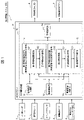
- FIG. 1 is a system configuration diagram showing the configuration of a rear warning system to which an embodiment of a rear warning device (rear monitoring device) of the present invention is applied;
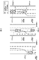
- FIG. 2 is an image diagram during a lane change when the lane change is performed with the rear warning system to which the present invention is applied.
- FIG. 2 is an image diagram from before the start of the lane change to after the lane change when the rear warning system to which the present invention is applied is installed and the lane is changed.
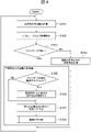
- 1 is a flow chart showing an embodiment of a processing procedure of a rear warning device (rear monitoring device) of the present invention; The figure which shows the moving amount
- FIG. 1 is a system configuration diagram showing the configuration of a rear warning system to which one embodiment of a rear warning device (rear monitoring device) according to the present invention is applied.
- the rear warning system 50 of the illustrated embodiment is mounted on a vehicle (hereinafter also referred to as own vehicle or own vehicle), monitors the rear of the vehicle, and detects other objects (vehicles, etc.) that rapidly approach from behind the vehicle. This is a system that assists the driver in changing lanes by detecting a moving object) and issuing an alarm.
- a vehicle hereinafter also referred to as own vehicle or own vehicle
- the rear warning system 50 of this embodiment has a millimeter wave radar 1, a steering angle sensor 2, a yaw rate sensor 3, a wheel speed sensor 4, a vehicle ECU 5, an alarm display LED 6, an alarm notification buzzer 7, and an ADAS ECU 8.
- the millimeter wave radar 1 is composed of one or more millimeter wave radars for detecting objects existing behind the own vehicle.
- the millimeter-wave radar 1 transmits radio waves to a predetermined range behind the own vehicle and receives the reflected waves to detect the relative position of an object behind the own vehicle and the relative speed with respect to the own vehicle. For example, two mounting positions are mounted at different angles on the left and right sides of the rear surface of the own vehicle.
- the millimeter wave radar is used as an external sensor device for recognizing and acquiring external world information around the own vehicle. good.
- the steering angle sensor 2 and yaw rate sensor 3 detect the steering angle (steering wheel angle) and yaw rate of the vehicle, respectively.
- the wheel speed sensor 4 detects the vehicle speed of the own vehicle by detecting the wheel speed pulse of the own vehicle.
- the vehicle ECU 5 outputs left and right turn signal information of the own vehicle to the ADAS ECU 8.
- the alarm display LED 6 and alarm notification buzzer 7 are devices for notifying the driver of the alarm calculated by the ADAS ECU 8 by display and sound when there is an alarm.
- the ADAS ECU 8 is mainly composed of a computer including a CPU, RAM, ROM, etc. In this example, it includes a rear warning device (rear monitoring device) 10.
- the rear warning device 10 of the ADAS ECU 8 inputs information of the own vehicle (vehicle information) and determines whether or not there is a warning.
- the rear warning device 10 of the present embodiment includes a movement history acquisition unit 11, an object detection unit 12, a lane change determination unit (route change determination unit) 13, a first warning determination processing unit 14, a second warning determination processing unit 15, an alarm It has a reporting unit 16 .
- the first warning determination processing unit 14 includes a first warning range setting unit 141 and a first warning necessity determination unit 142
- the second warning determination processing unit 15 includes a traveling route estimation unit 150, a second warning range setting unit 151 and second warning necessity determination unit 152 .
- the movement history acquisition unit 11 uses the vehicle speed, rotation angle, etc. of the vehicle based on signals acquired from sensors mounted on the vehicle (steering angle sensor 2, yaw rate sensor 3, wheel speed sensor 4) to determine the movement history of the vehicle.
- Vehicle movement history information relating to the movement history of the vehicle is acquired by calculating the amount of movement of the vehicle.
- Vehicle movement history information is acquired using map information and navigation information of the vehicle, sensor information acquired from sensors installed outside the vehicle, information acquired through vehicle-to-vehicle communication, and vehicle-to-infrastructure communication.
- the object detection unit 12 detects the relative position and relative speed of an object behind the own vehicle from the signal (external information) acquired from the millimeter wave radar 1 .
- the lane change determination unit 13 determines the start and completion of the lane change (course change) of the host vehicle from left and right turn signal information (on/off operation information) output by the vehicle ECU 5 .
- the presence or absence of the lane change of the own vehicle is determined by the steering wheel instead of the turn signal on/off operation information or together with the turn signal on/off operation information. It may be determined when the movement of the own vehicle (more specifically, the distance from the current lane of the own vehicle by a specified value or more) is detected based on the amount of change in the angle or the like. That is, for example, the start of the lane change of the own vehicle (accompanied by the estimation of the own vehicle position assuming that the lane is not changed, which will be described later) may be determined in the first cycle when the turn signal is turned on, or the turn signal is turned on. It may be determined when it is turned on and/or when it is detected that the host vehicle has started to leave the current lane of the host vehicle (more than a specified value) (for example, it is determined by the amount of change in the steering wheel angle).
- the first warning determination processing unit 14 operates when the lane change determination unit 13 determines that the vehicle is not changing lanes, and performs warning determination processing for other than lane changes.
- the vehicle movement history information acquired by the movement history acquisition unit 11 is used to determine whether or not the vehicle is in danger of rapidly approaching behind the vehicle when the vehicle is traveling, except when the vehicle is changing lanes. Determine if the vehicle does not exist.
- the first alarm determination processing unit 14 uses the own vehicle movement history information acquired by the movement history acquisition unit 11 to monitor the presence (approach) of other moving objects that rapidly approach behind the own vehicle.
- a first warning range setting unit 141 that sets the warning range (monitoring range) for issuing a warning as a
- the first warning necessity determination unit 142 is provided to determine the moving object to be warned and included in the warning range.
- the setting method of the alarm range here is well-known, detailed description is omitted in this specification.
- the second warning determination processing unit 15 operates when the lane change determination unit 13 determines that the vehicle is changing lanes, and performs warning determination processing during lane changes.
- the traveling route estimation unit 150 estimates the own vehicle traveling route information (described later), and the own vehicle movement history acquired by the movement history acquisition unit 11 while the own vehicle is changing lanes. Using the information and the vehicle traveling route estimation information estimated by the traveling route estimation unit 150, it is determined whether or not there is a dangerous vehicle rapidly approaching the vehicle from behind. As described above, this processing is performed when the blinker is on.
- the second warning determination processing unit 15 provides own vehicle travel route information (own vehicle position information), the vehicle movement history information, and the vehicle traveling path estimation information, the presence (approach) of another moving object that rapidly approaches the vehicle from behind is detected.
- a second alarm range setting unit (monitoring range setting unit) 151 that sets a warning range (monitoring range) for monitoring and issuing a warning, presence or absence of other moving objects included in the warning range, and movement thereof
- a second warning necessity judgment unit 152 is provided for judging whether or not an alarm is necessary for an object (that is, a moving object to be alarmed and included in the alarm range).
- the traveling route estimation unit 150 the method of estimating the own vehicle traveling route information by the traveling route estimation unit 150, the method of setting the warning range by the second warning range setting unit 151, and the determination method by the second warning necessity determination unit 152 will be described later. do.
- the alarm issuing unit 16 determines whether an alarm is required (i.e., , there is a moving object subject to warning within the warning range), an alarm command for issuing an alarm is output to the alarm display LED 6 and the alarm notification buzzer 7 .
- Fig. 2 is an image diagram during a lane change when the rear warning system to which the present invention is applied is installed and the lane is changed.
- the dashed-dotted line in the figure represents the running track of the own vehicle 20 .
- x is the movement history of the vehicle 20 before the lane change starts, and .tangle-solidup.
- the warning range 21 is determined in the center lane to which the vehicle 20 changes lanes ( Second alarm range setting unit 151) (details will be explained later).
- the other vehicle 25 is a dangerous vehicle (another moving body) that is rapidly approaching the own vehicle 20 and is within the warning range 21 (second warning necessity determination unit 152), so that an alarm is output (an alarm is issued). information unit 16).
- the other vehicle 26 is a vehicle existing in the lane ahead of the lane change (the right lane of the three-lane road) and is outside the warning range 21, so no warning is output.
- Fig. 3 is an image diagram from before the start of the lane change to after the lane change when the rear warning system to which the present invention is applied is installed.
- FIG. 3 only the warning range for the rear and right side (right rear lane) of the own vehicle 20 is described, but the warning range for the rear and left side (left rear lane) of the own vehicle 20 is the same. be.
- the movement history of the own vehicle 20 acquired by the movement history acquisition unit 11 before the start of the lane change is used to set the warning range 21 to the adjacent lane (central lane) of the current lane of the own vehicle 20.
- Set (first alarm range setting unit 141) (see the left diagram in FIG. 3).
- the warning range 21 is set in the driving lane (center lane) to which the vehicle 20 is to change lanes (second 2 alarm range setting unit 151) (see the central diagram of FIG. 3).
- the movement history of the vehicle 20 includes the lane change for a certain period of time after completion, and the movement history does not follow the lane.
- the movement history of the vehicle 20 acquired by the movement history acquisition unit 11 is not used, and the warning range 21 is fixed (fixed to the warning range 21 set in the center lane, which is the driving lane where the vehicle 20 changes lanes) ( For example, a rectangle) and determination is made (second alarm range setting unit 151).
- the warning range 21 set to the adjacent lane (right lane) of the driving lane of the own vehicle 20 after the course change is completed) is used (first warning range setting unit 141) (see the right diagram of FIG. 3).
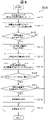
- FIG. 4 is a flow chart showing one embodiment of the processing procedure of the rear warning device according to the present invention.
- This processing is processed within the ADAS ECU8. This process starts when the own vehicle exceeds a certain speed while it is running. In general, this processing is determined in S103 as to whether or not there is a blinker (on/off operation information), and if there is a blinker, it is determined that the lane is being changed, and lane change warning determination processing (S105 to S108) is performed. . If there is no blinker, it is assumed that the vehicle is not changing lanes (driving in the same lane), and an alarm determination process (S104) is performed to indicate that the vehicle is not changing lanes.
- S104 alarm determination process
- ⁇ t is the processing time [s] for one cycle
- Vs [m/s] and ⁇ t+1 [rad] are the vehicle speed and rotation angle of the own vehicle based on the signal obtained from the sensor.
- ⁇ Object detection processing object detection unit 12>
- an object hereinafter also referred to as a target
- the millimeter wave radar 1 the relative position and relative speed of the object are obtained.
- the relative position of the detected object is transformed into a coordinate system centered on the front end of the vehicle.
- ⁇ Lane change determination processing (lane change determination unit 13)>
- S103 it is determined whether the blinker is on in the current cycle. If the blinker is off (specifically, after a certain period of time has passed since the blinker is off), it is determined that the lane has not been changed, and the warning determination process of S104 other than lane change is performed. If the blinker is on (more specifically, until a certain period of time has passed since the blinker is turned off), it is determined that the lane is being changed, and the lane change warning determination process of S105 to S108 is started.
- an alarm command for issuing an alarm is issued to the alarm issuing unit 16 by the alarm display LED 6 or the alarm notification It instructs the buzzer 7 to output.
- the vehicle position information (vehicle traveling route information) is estimated assuming that the vehicle does not change lanes (in other words, it continues to travel in the current lane when the lane change starts).
- the vehicle traveling route is estimated using a vehicle model including vehicle information.
- the own vehicle traveling route estimation is performed differently depending on whether the vehicle is traveling on a straight line or on a curve. This process is determined based on, for example, the steering wheel angle and yaw rate.
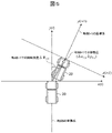
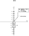
- FIG. 6 shows an example of estimating the course of the vehicle during straight running. In the figure, points after P t+1 are estimated.
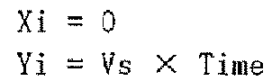
- the traveling path P i (Xi, Yi)[m] of the own vehicle assuming that the vehicle does not change lanes while traveling straight can be obtained by the following formula.
- Vs is the vehicle speed [m/s]
- subscript i indicates what order (how many cycles ahead) the prediction result is.
- P t+3 represents the coordinates of the prediction result for the t+3 cycle.
- Time is the prediction time. For example, if one cycle is 0.5s and the prediction results up to 10s ahead are used, a value obtained by adding every 0.5s from 0.5s to 10s is used.
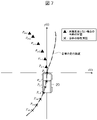
- FIG. 7 shows an example of vehicle traveling path estimation when traveling on a curve.
- points after P t+1 are estimated.
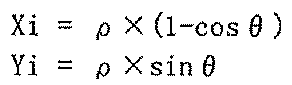
- the traveling path P i (Xi, Yi)[m] of the own vehicle assuming that the vehicle does not change lanes while traveling on a curve is obtained by the following formula.
- the subscript i indicates what number (how many cycles ahead) the prediction result is. For example, when the current time is t, P t+3 represents the coordinates of the prediction result for the t+3 cycle.
- the turning radius ⁇ [m] and the rotation angle ⁇ [rad] are obtained by the following formulas.
- Vs is the vehicle speed [m/s]
- ⁇ is the yaw rate [rad/s]
- Time is the predicted time.
- Estimated coordinates P i (Xi, Yi) are obtained by converting the equation of the orthogonal coordinate system into the polar coordinate system.
- ⁇ [rad] is obtained by the following formula.
- Time is the prediction time. For example, when using prediction results up to 10 seconds ahead in 0.5 seconds per cycle, use a value obtained by adding every 0.5 seconds from 0.5 seconds to 10 seconds.
- the movement history (vehicle movement history information) and the point group of the vehicle position (vehicle travel route information) assuming that the vehicle does not change lanes are moved and rotated to a coordinate system centered on the current front end of the vehicle. do.
- time t+1 it is obtained by the following formula using the movement amount ( ⁇ x t+1 , ⁇ y t+1 ) from t to t+1 and the rotation angle ⁇ t+1 .
- FIG. 8 is a flow chart showing the processing procedure of alarm condition judgment (S108).
- the processing up to S118 is repeated for the number of targets detected by the millimeter wave radar 1 (S102).
- FIG. 9 is a diagram showing an example of this processing when the lane is changed to the right at time t and current time t+3. Based on the movement history P t-7 to P t-1 before the start of the lane change, and the vehicle position P t to P t+2 when it is assumed that the lane is not changed, search for the target S on the right side in the direction of the lane change. I do.
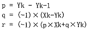
- the y coordinate value Yt-2 of the movement history P t-2 and the y coordinate value Yt- 3 of the movement history P t-3 satisfy Yt-3 ⁇ Sy and Sy ⁇ Yt-2, so P t -2 and P t-3 are search results.
- S112 it is determined whether or not the point of the search result of S111 exists. If it exists, it is determined that the point can be a warning target, and the process proceeds to S113. If it does not exist, it is assumed that the point is not an alarm target, and the processing of S113 to S118 is skipped.
- a determination threshold value dTH including a lower limit value dTH1 and an upper limit value dTH2 is set.
- the lane change time more specifically, the elapsed time after the start of the lane change
- the steering wheel angle are used. From the determination result of the number of lanes to be changed, for example, in the case of a lane change for one lane, the lower limit value dTH1 and the upper limit value dTH2 are determined as follows when the width of the own vehicle is Lv [m].
- the lower limit value dTH1 means that the warning range is 0.5m from the side of the vehicle
- the upper limit value dTH2 is 0.5m from the side of the vehicle (that is, the lower limit value dTH1) and an additional 3m. means to be in range.
- the lower limit value dTH1 and the upper limit value dTH2 are determined as follows from the determination result of the number of lanes to be changed.
- the lower limit value dTH1 means that the warning range will be from 0.5m ahead of the side of the vehicle and 1 lane (1 lane is 3m), and the upper limit value dTH2 is 3m further from the lower limit value dTH1. is the alarm range.
- a similar method can be used to extend lane changes for three or more lanes.
- values of 0.5m and 3m are examples, and may be fixed values that match the road environment on which the vehicle is traveling, or may be variable values that can be variably set according to the road environment on which the vehicle is traveling.
- a warning range (monitoring range) determined by is set to the driving lane behind the host vehicle that is changing lanes and ahead of the lane change.
- the detection range of the millimeter wave radar 1 as the external sensor device is set in advance so that such an alarm range (monitoring range) can be set in the lane to which the vehicle is changing lanes.
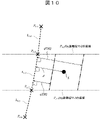
- FIG. 10 is an image diagram of the processing of S116, and is an enlarged diagram of P t-2 and P t-3 and the vicinity of the target S in FIG.
- d is the distance between L t-2 and target S.
- the lower limit value dTH1 and the upper limit value dTH2 obtained in S115 are distances from L k (L t-2 in this example), like d. If the condition of S116 is satisfied, S117 is performed assuming that the target S is within the warning range. If the condition of S116 is not satisfied, S117 and S118 are skipped on the assumption that the target S is not an object to be warned.
- the warning issuing unit 16 is instructed to output a warning command for issuing a warning to the warning display LED 6 and the warning buzzer 7.
- a warning command for issuing a warning to the warning display LED 6 and the warning buzzer 7.
- the rear warning device (rear monitoring device) 10 includes the movement history acquisition unit 11 that acquires the movement history of the own vehicle and the A course estimation unit 150 for estimating the course of the host vehicle (own vehicle position) in the future when the host vehicle starts to change course, and the movement history of the host vehicle before the start of the course change and ( An alarm range for monitoring the presence of other moving bodies (other moving bodies rapidly approaching from behind the own vehicle) based on the estimated course when the own vehicle starts to change course.
- a second alarm range setting unit (monitoring range setting unit) 151 that sets the (monitoring range), and an alarm issuing unit 16 that issues an alarm when another moving body is included in the warning range (monitoring range) , provided.
- the traveling route estimation unit 150 estimates the traveling route of the own vehicle by using the traveling route estimation from the vehicle information before the course change of the own vehicle, or estimates the movement history of the own vehicle before the course change.
- the course of the own vehicle is estimated by extrapolating from the point cloud of .
- the warning range is determined by the movement history of the own vehicle and the position of the own vehicle when it is assumed that the lane is not changed even during the lane change (in other words, , the position of the own vehicle when it is assumed that the lane was not changed is estimated, and based on that information, the warning range for the lane to which the lane is changed is set), so an object approaching from behind ( (moving objects) can be properly estimated, and false alarms and no alarms during lane changes can be reduced.
- the first warning determination processing unit 14 (first warning range setting unit 141, first warning necessity determination unit 142) that performs warning determination processing other than during lane change
- the second warning determination processing unit 15 (traveling route estimation unit 150, second warning range setting unit 151, second warning necessity determination unit 152) that performs the warning determination process is configured separately (separate functional block).
- the first warning determination processing unit 14 and the second warning determination processing unit 15 are combined into one functional block, and within that functional block, different processing (lane change A warning determination process other than during a lane change, and a warning determination process during a lane change) may be performed.
- the alarm when it is determined that there is a moving object to be warned within the set warning range, the alarm is issued to the alarm display LED 6 and the alarm notification buzzer 7.
- a moving object approaching the above-mentioned warning range from behind is used as the monitoring range to monitor, and when it is determined that there is a moving object to be monitored within the monitoring range, the vehicle is automatically controlled to avoid collision with the moving object.
- this embodiment may be used for support.
- the rear warning device (rear monitoring device) 10 is included in (built into) the ADAS ECU 8, which is the control device mounted on the vehicle, but the rear warning device (rear monitoring device ) 10 may be included in an external sensor device for recognizing and acquiring external world information around the own vehicle, such as a millimeter wave radar 1, for example, and may be integrated. It is natural.
- the present invention is not limited to the above-described embodiments, and includes various modifications.
- the above-described embodiments have been described in detail in order to explain the present invention in an easy-to-understand manner, and are not necessarily limited to those having all the configurations described.
- part of the configuration of one embodiment can be replaced with the configuration of another embodiment, and the configuration of another embodiment can be added to the configuration of one embodiment.
- each of the above configurations, functions, processing units, processing means, and the like may be realized by hardware, for example, by designing a part or all of them using an integrated circuit.
- ⁇ may be realized by software by a processor interpreting and executing a program for realizing each function.
- Information such as programs, tables, and files that implement each function can be stored in memory, hard disks, SSD (Solid State Drives), and other recording devices, or IC cards, SD cards, DVDs, and other recording media.
- First alarm determination processing unit (during lane change 141 First warning range setting unit 142 First warning necessity determination unit 15 Second warning determination processing unit (alarm determination processing during lane change) 150 Traveling route estimation unit , 151 second warning range setting unit (monitoring range setting unit), 152 second warning necessity determination unit 16 warning issuing unit 20 own vehicle, 21 warning range (monitoring range), 25 other Vehicle (with alarm), 26... Other vehicle (without alarm), 50... Rear alarm system
Landscapes
- Engineering & Computer Science (AREA)
- Automation & Control Theory (AREA)
- Transportation (AREA)
- Mechanical Engineering (AREA)
- Human Computer Interaction (AREA)
- Physics & Mathematics (AREA)
- General Physics & Mathematics (AREA)
- Traffic Control Systems (AREA)
- Control Of Driving Devices And Active Controlling Of Vehicle (AREA)
Abstract
Description
図1は、本発明に関わる後方警報装置(後方監視装置)の一実施形態を適用した後方警報システムの構成を示すシステム構成図である。
本実施形態の後方警報装置10は、移動履歴取得部11、物体検知部12、車線変更判断部(進路変更判断部)13、第1警報判定処理部14、第2警報判定処理部15、警報発報部16を有する。また、第1警報判定処理部14は、第1警報範囲設定部141、第1警報要否判断部142を備え、第2警報判定処理部15は、進行路推定部150、第2警報範囲設定部151、第2警報要否判断部152を備える。
移動履歴取得部11は、本例では、自車両に搭載されたセンサ(操舵角センサ2、ヨーレートセンサ3、車輪速センサ4)から取得した信号に基づく自車両の車速と回転角度等から、自車両の移動量を計算することによって、自車両の移動履歴に関する自車移動履歴情報を取得する。
物体検知部12は、ミリ波レーダ1から取得した信号(外界情報)から、自車両の後方の物体の相対位置と相対速度を検知する。
車線変更判断部13は、本例では、車両ECU5が出力する左右のウインカー情報(オンオフ操作情報)から、自車両の車線変更(進路変更)の開始及び完了を判断する。
第1警報判定処理部14は、車線変更判断部13で車線変更中以外と判断された場合に動作し、車線変更中以外の警報判定処理を実施する。この車線変更中以外の警報判定処理では、移動履歴取得部11で取得した自車移動履歴情報を用いて、自車両の車線変更以外の走行時に自車両の後方に急速に接近するような危険な車両が存在しないかを判断する。
第2警報判定処理部15は、車線変更判断部13で車線変更中と判断された場合に動作し、車線変更中の警報判定処理を実施する。この車線変更中の警報判定処理では、進行路推定部150で自車進行路情報を推定すると共に(後で説明)、自車両の車線変更中に移動履歴取得部11で取得した自車移動履歴情報と進行路推定部150で推定した自車進行路推定情報を用いて、自車両の後方から急速に接近する危険な車両が存在しないかを判断する。前述のように本処理はウインカーがオンの時に実施する。
警報発報部16は、第1警報判定処理部14(の第1警報要否判断部142)又は第2警報判定処理部15(の第2警報要否判断部152)により、警報要(つまり、警報範囲に含まれる警報対象となる移動体有り)と判断された場合に、警報表示用LED6、警報通知用ブザー7に対して、警報を発報するための警報指令を出力する。
図4は、本発明に関わる後方警報装置の処理手順の一実施形態を示すフローチャートである。本処理はADAS ECU8内で処理を行う。本処理は、自車両が走行中、一定速度を超えた場合に処理を開始する。本処理を概略的に述べると、S103でウインカーの有無(オンオフ操作情報)を判断し、ウインカーがある場合には車線変更中であるとして、車線変更中の警報判定処理(S105~S108)を行う。ウインカーがない場合には車線変更中でない(同じ走行車線を走行中)として、車線変更中以外の警報判定処理(S104)を行う。
S101では、自車両の移動量(自車移動履歴情報に対応)の計算を行う。図5のように、時刻t+1の時の移動量と回転角度を(Δxt+1,Δyt+1)、Δθt+1とする時、以下の式で(Δxt+1,Δyt+1)が求められる。

S102では、ミリ波レーダ1で自車両の後方の物体(以下、物標とも称する)を検知し、その物体の相対位置と相対速度を求める。検知された物体の相対位置は自車両先端を中心とする座標系へ変換する。
S103では、現在のサイクルでウインカーがオンかどうかを判断する。ウインカーがオフ(詳しくは、ウインカーがオフとなって一定時間が経過した後)の場合は、車線変更を行っていないと判断し、S104の車線変更中以外の警報判定処理を行う。ウインカーがオン(詳しくは、ウインカーがオフとなって一定時間が経過するまで)の場合は、車線変更中であると判断し、S105~S108の車線変更中の警報判定処理を開始する。
S104では、車線変更中以外の警報判定処理を行う。その際、S101で求めた移動量から現在の自車両先端を中心とする座標系の自車移動履歴情報を算出する。また、算出した自車移動履歴情報を用いて、自車両の後方に急速に接近するような他の移動体の存在(進入)を監視して警報を発報するための警報範囲(監視範囲)を(隣接車線に)設定し、警報範囲に含まれる他の移動体の有無、並びに、その移動体に対する警報の要否(つまり、警報範囲に含まれる警報対象となる移動体)を判断する。警報要(つまり、警報範囲に含まれる警報対象となる移動体有り)と判断した場合に、警報発報部16に対して、警報を発報するための警報指令を警報表示用LED6や警報通知用ブザー7に出力するよう指示する。
≪進行路推定処理(進行路推定部150)≫
S105では、ウインカーオン後の最初のサイクルであるかどうかを判断する。ウインカーオン後の最初のサイクルである場合には、S106を行い、そうでない場合にはS106をスキップし、S107へ移行する。
上記推定は、車両情報を含む車両モデルを用いて自車進行路推定を行う。自車進行路推定は、直線走行時とカーブ走行時で異なる処理を行う。この処理の判断は、例えば、ハンドル角やヨーレートによって判断する。図6は直線走行時の自車進行路推定の例である。図中では、Pt+1以降の点を推定する。直線走行時の車線変更しなかったと仮定した場合の自車両の進行路Pi(Xi,Yi)[m]は以下の式で求められる。

S106の自車両が車線変更しないと仮定した場合の自車位置(自車進行路)の推定を自車両の移動履歴の点群から外挿してもよい。




S111では、ミリ波レーダ1で検知した物標Sのy座標の値SyがYk-1<SyかつSy<Ykとなる点を探索する。図9は、時刻tで右方向へ車線変更を行い、現時刻t+3の時の本処理の例を示す図である。車線変更開始前の移動履歴Pt-7~Pt-1、車線変更しないと仮定した場合の自車位置Pt~Pt+2より車線変更方向である右側の物標Sに対して探索を行う。本例では、移動履歴Pt-2のy座標値Yt-2、移動履歴Pt-3のy座標値Yt-3より、Yt-3<SyかつSy<Yt-2を満たすため、Pt-2とPt-3が探索結果となる。
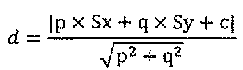
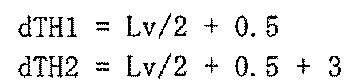
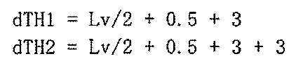
S116では、S114で求めたdがdTH1<dかつd<dTH2を満たすか(変更車線数に応じた判定閾値dTH内に含まれるか)を判定する。図10はS116の処理のイメージ図であり、図9のPt-2とPt-3と物標S付近を拡大した図である。本例では、dはLt-2と物標Sとの距離である。S115で求めた下限値dTH1と上限値dTH2は、dと同様にLk(本例ではLt-2)からの距離である。S116の条件を満たす場合は、警報範囲内に物標SがあるとしてS117を行う。S116の条件を満たさない場合は、警報対象となる物標Sではないとして、S117、S118をスキップする。
以上のように、本実施形態に関わる後方警報装置(後方監視装置)10は、自車両の移動履歴を取得する移動履歴取得部11と、前記自車両が進路変更(車線変更)しないと仮定した場合の将来の前記自車両の進行路(自車位置)を推定する進行路推定部150と、前記自車両が進路変更を開始した場合に、前記自車両の進路変更開始前の移動履歴及び(前記自車両が進路変更を開始したときに)前記推定された進行路に基づいて、他の移動体(自車両の後方から急速に接近してくる他の移動体)の存在を監視する警報範囲(監視範囲)を設定する第2警報範囲設定部(監視範囲設定部)151と、前記警報範囲(監視範囲)に他の移動体が含まれる場合に警報を発報する警報発報部16と、を備える。
Claims (13)
- 自車両の移動履歴を取得する移動履歴取得部と、
前記自車両が進路変更しないと仮定した場合の将来の前記自車両の進行路を推定する進行路推定部と、
前記自車両が進路変更を開始した場合に、前記自車両の進路変更開始前の移動履歴及び前記推定された進行路に基づいて、他の移動体の存在を監視する監視範囲を設定する監視範囲設定部と、を備える後方監視装置。 - 前記監視範囲に他の移動体が含まれる場合に警報を発報する警報発報部を更に備える、請求項1に記載の後方監視装置。
- 前記進行路推定部は、前記自車両の進路変更前の車両情報から進行路推定を用いて前記自車両の進行路の推定を行う、請求項1に記載の後方監視装置。
- 前記進行路推定部は、前記自車両の進路変更前の移動履歴の点群から外挿することで前記自車両の進行路の推定を行う、請求項1に記載の後方監視装置。
- 前記自車両が進路変更を開始したか否かを判断する進路変更判断部を更に備え、
前記進路変更判断部は、前記自車両のウインカーがオンのとき、又は、前記自車両が現在の前記自車両の走行車線を離れ始めたときの少なくとも一方のときに、前記自車両が進路変更を開始したと判断する、請求項1に記載の後方監視装置。 - 前記進行路推定部は、前記自車両が進路変更を開始した場合に、前記自車両の進行路の推定を行う、請求項1に記載の後方監視装置。
- 前記進行路推定部は、前記自車両のウインカーがオンのとき、又は、前記自車両が現在の前記自車両の走行車線を離れ始めたときの少なくとも一方のときに、前記自車両の進行路の推定を行う、請求項1に記載の後方監視装置。
- 前記監視範囲設定部は、
前記自車両の後方に他の移動体を検知した場合に、
前記自車両の進路変更開始前の移動履歴及び前記推定された進行路に対する前記他の移動体の距離を求め、
前記自車両の進路変更開始前の移動履歴及び前記推定された進行路に対する、変更車線数に応じた判定閾値を設定して、前記監視範囲とする、請求項1に記載の後方監視装置。 - 前記監視範囲設定部は、前記自車両が進路変更を開始してからの経過時間、又は、前記自車両のハンドル角の少なくとも一方に基づいて、前記変更車線数に応じた判定閾値を設定する、請求項8に記載の後方監視装置。
- 前記監視範囲に他の移動体が含まれる場合に警報を発報する警報発報部を更に備え、
前記警報発報部は、前記他の移動体の前記距離が前記変更車線数に応じた判定閾値内に含まれる場合に警報を発報する、請求項8に記載の後方監視装置。 - 前記監視範囲設定部は、
前記自車両が進路変更を開始する前に、前記自車両の進路変更開始前の移動履歴に基づいて、現在の前記自車両の走行車線の隣接車線に前記監視範囲を設定し、
前記自車両が進路変更を開始した場合に、前記自車両の進路変更開始前の移動履歴及び前記推定された進行路に基づいて、前記自車両の進路変更先の走行車線に前記監視範囲を設定し、
前記自車両が進路変更を完了した場合に、前記自車両の進路変更完了後の移動履歴に基づいて、進路変更完了後の前記自車両の走行車線の隣接車線に前記監視範囲を設定する、請求項1に記載の後方監視装置。 - 前記監視範囲設定部は、
前記自車両が進路変更を完了した場合に、完了後一定時間は、前記自車両の進路変更先の走行車線に設定した前記監視範囲を用い、完了後一定時間が経過した後、前記自車両の進路変更完了後の移動履歴に基づいて、進路変更完了後の前記自車両の走行車線の隣接車線に前記監視範囲を設定する、請求項11に記載の後方監視装置。 - 前記後方監視装置は、前記自車両に搭載された制御装置に含まれる、又は、前記自車両の外界情報を認識する外界センサ装置に含まれる、請求項1に記載の後方監視装置。
Priority Applications (2)
| Application Number | Priority Date | Filing Date | Title |
|---|---|---|---|
| JP2023500516A JP7486657B2 (ja) | 2021-02-22 | 2021-09-16 | 後方監視装置 |
| DE112021006038.4T DE112021006038T5 (de) | 2021-02-22 | 2021-09-16 | Rücksicht-überwachungsvorrichtung |
Applications Claiming Priority (2)
| Application Number | Priority Date | Filing Date | Title |
|---|---|---|---|
| JP2021025912 | 2021-02-22 | ||
| JP2021-025912 | 2021-02-22 |
Publications (1)
| Publication Number | Publication Date |
|---|---|
| WO2022176245A1 true WO2022176245A1 (ja) | 2022-08-25 |
Family
ID=82931321
Family Applications (1)
| Application Number | Title | Priority Date | Filing Date |
|---|---|---|---|
| PCT/JP2021/034117 Ceased WO2022176245A1 (ja) | 2021-02-22 | 2021-09-16 | 後方監視装置 |
Country Status (3)
| Country | Link |
|---|---|
| JP (1) | JP7486657B2 (ja) |
| DE (1) | DE112021006038T5 (ja) |
| WO (1) | WO2022176245A1 (ja) |
Citations (5)
| Publication number | Priority date | Publication date | Assignee | Title |
|---|---|---|---|---|
| JPH10166974A (ja) * | 1996-12-09 | 1998-06-23 | Mitsubishi Motors Corp | 車両の後側方警報装置 |
| JP2000344033A (ja) * | 1999-06-02 | 2000-12-12 | Mitsubishi Electric Corp | 車両の車線変更時警報装置 |
| JP2008247385A (ja) * | 2003-11-07 | 2008-10-16 | Nissan Motor Co Ltd | 車両用運転操作補助装置および車両用運転操作補助装置を備えた車両 |
| WO2013018673A1 (ja) * | 2011-08-02 | 2013-02-07 | 日産自動車株式会社 | 立体物検出装置及び立体物検出方法 |
| JP2018101376A (ja) * | 2016-12-22 | 2018-06-28 | 三菱自動車工業株式会社 | 運転支援装置 |
Family Cites Families (1)
| Publication number | Priority date | Publication date | Assignee | Title |
|---|---|---|---|---|
| JP5493342B2 (ja) | 2008-12-01 | 2014-05-14 | トヨタ自動車株式会社 | 物体位置検出装置 |
-
2021
- 2021-09-16 WO PCT/JP2021/034117 patent/WO2022176245A1/ja not_active Ceased
- 2021-09-16 JP JP2023500516A patent/JP7486657B2/ja active Active
- 2021-09-16 DE DE112021006038.4T patent/DE112021006038T5/de active Pending
Patent Citations (5)
| Publication number | Priority date | Publication date | Assignee | Title |
|---|---|---|---|---|
| JPH10166974A (ja) * | 1996-12-09 | 1998-06-23 | Mitsubishi Motors Corp | 車両の後側方警報装置 |
| JP2000344033A (ja) * | 1999-06-02 | 2000-12-12 | Mitsubishi Electric Corp | 車両の車線変更時警報装置 |
| JP2008247385A (ja) * | 2003-11-07 | 2008-10-16 | Nissan Motor Co Ltd | 車両用運転操作補助装置および車両用運転操作補助装置を備えた車両 |
| WO2013018673A1 (ja) * | 2011-08-02 | 2013-02-07 | 日産自動車株式会社 | 立体物検出装置及び立体物検出方法 |
| JP2018101376A (ja) * | 2016-12-22 | 2018-06-28 | 三菱自動車工業株式会社 | 運転支援装置 |
Also Published As
| Publication number | Publication date |
|---|---|
| DE112021006038T5 (de) | 2023-10-05 |
| JPWO2022176245A1 (ja) | 2022-08-25 |
| JP7486657B2 (ja) | 2024-05-17 |
Similar Documents
| Publication | Publication Date | Title |
|---|---|---|
| US11987238B2 (en) | Driving support apparatus | |
| US10446034B2 (en) | Driving support system | |
| CN107615092B (zh) | 车辆控制装置以及车辆控制方法 | |
| JP5962706B2 (ja) | 運転支援装置 | |
| CN115702449B (zh) | 驾驶辅助装置 | |
| US20150353078A1 (en) | Driving assistance apparatus | |
| EP3141926A1 (en) | Automated detection of hazardous drifting vehicles by vehicle sensors | |
| KR102106347B1 (ko) | 후측방 경보 장치 및 그 후측방 경보 방법 | |
| EP3576071B1 (en) | Alarm system for vehicle | |
| CN106663379A (zh) | 用于具有拖车的车辆的增强的盲点检测 | |
| JP6858178B2 (ja) | 監視装置および監視方法 | |
| CN109017776B (zh) | 安装在车辆中的驾驶辅助系统 | |
| JP2014197326A (ja) | 運転支援装置 | |
| JP2018097765A (ja) | 物体検出装置、及び物体検出方法 | |
| JP7272228B2 (ja) | 車両用運転支援装置及び車両用運転支援方法 | |
| JP2014241115A (ja) | 周辺物体検知装置 | |
| US20210327274A1 (en) | Driving assistance device | |
| JP2004295620A (ja) | 車両衝突可能性検出装置 | |
| WO2023276616A1 (ja) | 運転支援装置 | |
| JP7486657B2 (ja) | 後方監視装置 | |
| JP2015054603A (ja) | 対象物検知装置 | |
| US20230182722A1 (en) | Collision avoidance method and apparatus | |
| CN117261885A (zh) | 车辆及车辆的控制方法 | |
| CN117471469A (zh) | 障碍物检测方法、自移动设备及存储介质 | |
| JPH08339500A (ja) | 追従走行用車間距離警報装置 |
Legal Events
| Date | Code | Title | Description |
|---|---|---|---|
| 121 | Ep: the epo has been informed by wipo that ep was designated in this application |
Ref document number: 21926674 Country of ref document: EP Kind code of ref document: A1 |
|
| ENP | Entry into the national phase |
Ref document number: 2023500516 Country of ref document: JP Kind code of ref document: A |
|
| WWE | Wipo information: entry into national phase |
Ref document number: 112021006038 Country of ref document: DE |
|
| 122 | Ep: pct application non-entry in european phase |
Ref document number: 21926674 Country of ref document: EP Kind code of ref document: A1 |