EP3141926A1 - Automated detection of hazardous drifting vehicles by vehicle sensors - Google Patents
Automated detection of hazardous drifting vehicles by vehicle sensors Download PDFInfo
- Publication number
- EP3141926A1 EP3141926A1 EP15465539.3A EP15465539A EP3141926A1 EP 3141926 A1 EP3141926 A1 EP 3141926A1 EP 15465539 A EP15465539 A EP 15465539A EP 3141926 A1 EP3141926 A1 EP 3141926A1
- Authority
- EP
- European Patent Office
- Prior art keywords
- vehicle
- trajectory
- neighbouring
- anomalous
- lane markings
- Prior art date
- Legal status (The legal status is an assumption and is not a legal conclusion. Google has not performed a legal analysis and makes no representation as to the accuracy of the status listed.)
- Granted
Links
- 231100001261 hazardous Toxicity 0.000 title description 12
- 238000001514 detection method Methods 0.000 title description 8
- 230000002547 anomalous effect Effects 0.000 claims abstract description 44
- 238000000034 method Methods 0.000 claims abstract description 39
- 230000033001 locomotion Effects 0.000 claims abstract description 23
- 230000009471 action Effects 0.000 claims description 7
- 239000003550 marker Substances 0.000 description 7
- 238000004364 calculation method Methods 0.000 description 5
- 230000006870 function Effects 0.000 description 4
- 230000004913 activation Effects 0.000 description 3
- 230000010355 oscillation Effects 0.000 description 3
- 238000010586 diagram Methods 0.000 description 2
- 229940079593 drug Drugs 0.000 description 2
- 239000003814 drug Substances 0.000 description 2
- 238000003384 imaging method Methods 0.000 description 2
- 206010041349 Somnolence Diseases 0.000 description 1
- 238000013528 artificial neural network Methods 0.000 description 1
- 230000006399 behavior Effects 0.000 description 1
- 230000005540 biological transmission Effects 0.000 description 1
- 230000008859 change Effects 0.000 description 1
- 238000006243 chemical reaction Methods 0.000 description 1
- 238000004891 communication Methods 0.000 description 1
- 230000001788 irregular Effects 0.000 description 1
- 239000000463 material Substances 0.000 description 1
- 230000003287 optical effect Effects 0.000 description 1
- 230000005693 optoelectronics Effects 0.000 description 1
- 230000008569 process Effects 0.000 description 1
- 238000003672 processing method Methods 0.000 description 1
- 230000000007 visual effect Effects 0.000 description 1
Images


Classifications
-
- B—PERFORMING OPERATIONS; TRANSPORTING
- B60—VEHICLES IN GENERAL
- B60W—CONJOINT CONTROL OF VEHICLE SUB-UNITS OF DIFFERENT TYPE OR DIFFERENT FUNCTION; CONTROL SYSTEMS SPECIALLY ADAPTED FOR HYBRID VEHICLES; ROAD VEHICLE DRIVE CONTROL SYSTEMS FOR PURPOSES NOT RELATED TO THE CONTROL OF A PARTICULAR SUB-UNIT
- B60W30/00—Purposes of road vehicle drive control systems not related to the control of a particular sub-unit, e.g. of systems using conjoint control of vehicle sub-units, or advanced driver assistance systems for ensuring comfort, stability and safety or drive control systems for propelling or retarding the vehicle
- B60W30/08—Active safety systems predicting or avoiding probable or impending collision or attempting to minimise its consequences
- B60W30/095—Predicting travel path or likelihood of collision
- B60W30/0956—Predicting travel path or likelihood of collision the prediction being responsive to traffic or environmental parameters
-
- B—PERFORMING OPERATIONS; TRANSPORTING
- B60—VEHICLES IN GENERAL
- B60W—CONJOINT CONTROL OF VEHICLE SUB-UNITS OF DIFFERENT TYPE OR DIFFERENT FUNCTION; CONTROL SYSTEMS SPECIALLY ADAPTED FOR HYBRID VEHICLES; ROAD VEHICLE DRIVE CONTROL SYSTEMS FOR PURPOSES NOT RELATED TO THE CONTROL OF A PARTICULAR SUB-UNIT
- B60W30/00—Purposes of road vehicle drive control systems not related to the control of a particular sub-unit, e.g. of systems using conjoint control of vehicle sub-units, or advanced driver assistance systems for ensuring comfort, stability and safety or drive control systems for propelling or retarding the vehicle
- B60W30/08—Active safety systems predicting or avoiding probable or impending collision or attempting to minimise its consequences
- B60W30/095—Predicting travel path or likelihood of collision
- B60W30/0953—Predicting travel path or likelihood of collision the prediction being responsive to vehicle dynamic parameters
-
- B—PERFORMING OPERATIONS; TRANSPORTING
- B60—VEHICLES IN GENERAL
- B60W—CONJOINT CONTROL OF VEHICLE SUB-UNITS OF DIFFERENT TYPE OR DIFFERENT FUNCTION; CONTROL SYSTEMS SPECIALLY ADAPTED FOR HYBRID VEHICLES; ROAD VEHICLE DRIVE CONTROL SYSTEMS FOR PURPOSES NOT RELATED TO THE CONTROL OF A PARTICULAR SUB-UNIT
- B60W40/00—Estimation or calculation of non-directly measurable driving parameters for road vehicle drive control systems not related to the control of a particular sub unit, e.g. by using mathematical models
- B60W40/08—Estimation or calculation of non-directly measurable driving parameters for road vehicle drive control systems not related to the control of a particular sub unit, e.g. by using mathematical models related to drivers or passengers
- B60W40/09—Driving style or behaviour
-
- B—PERFORMING OPERATIONS; TRANSPORTING
- B60—VEHICLES IN GENERAL
- B60W—CONJOINT CONTROL OF VEHICLE SUB-UNITS OF DIFFERENT TYPE OR DIFFERENT FUNCTION; CONTROL SYSTEMS SPECIALLY ADAPTED FOR HYBRID VEHICLES; ROAD VEHICLE DRIVE CONTROL SYSTEMS FOR PURPOSES NOT RELATED TO THE CONTROL OF A PARTICULAR SUB-UNIT
- B60W50/00—Details of control systems for road vehicle drive control not related to the control of a particular sub-unit, e.g. process diagnostic or vehicle driver interfaces
- B60W50/08—Interaction between the driver and the control system
- B60W50/14—Means for informing the driver, warning the driver or prompting a driver intervention
-
- G—PHYSICS
- G01—MEASURING; TESTING
- G01S—RADIO DIRECTION-FINDING; RADIO NAVIGATION; DETERMINING DISTANCE OR VELOCITY BY USE OF RADIO WAVES; LOCATING OR PRESENCE-DETECTING BY USE OF THE REFLECTION OR RERADIATION OF RADIO WAVES; ANALOGOUS ARRANGEMENTS USING OTHER WAVES
- G01S13/00—Systems using the reflection or reradiation of radio waves, e.g. radar systems; Analogous systems using reflection or reradiation of waves whose nature or wavelength is irrelevant or unspecified
- G01S13/88—Radar or analogous systems specially adapted for specific applications
- G01S13/93—Radar or analogous systems specially adapted for specific applications for anti-collision purposes
- G01S13/931—Radar or analogous systems specially adapted for specific applications for anti-collision purposes of land vehicles
-
- G—PHYSICS
- G01—MEASURING; TESTING
- G01S—RADIO DIRECTION-FINDING; RADIO NAVIGATION; DETERMINING DISTANCE OR VELOCITY BY USE OF RADIO WAVES; LOCATING OR PRESENCE-DETECTING BY USE OF THE REFLECTION OR RERADIATION OF RADIO WAVES; ANALOGOUS ARRANGEMENTS USING OTHER WAVES
- G01S7/00—Details of systems according to groups G01S13/00, G01S15/00, G01S17/00
- G01S7/02—Details of systems according to groups G01S13/00, G01S15/00, G01S17/00 of systems according to group G01S13/00
- G01S7/41—Details of systems according to groups G01S13/00, G01S15/00, G01S17/00 of systems according to group G01S13/00 using analysis of echo signal for target characterisation; Target signature; Target cross-section
- G01S7/415—Identification of targets based on measurements of movement associated with the target
-
- G—PHYSICS
- G06—COMPUTING; CALCULATING OR COUNTING
- G06V—IMAGE OR VIDEO RECOGNITION OR UNDERSTANDING
- G06V20/00—Scenes; Scene-specific elements
- G06V20/50—Context or environment of the image
- G06V20/56—Context or environment of the image exterior to a vehicle by using sensors mounted on the vehicle
- G06V20/588—Recognition of the road, e.g. of lane markings; Recognition of the vehicle driving pattern in relation to the road
-
- B—PERFORMING OPERATIONS; TRANSPORTING
- B60—VEHICLES IN GENERAL
- B60W—CONJOINT CONTROL OF VEHICLE SUB-UNITS OF DIFFERENT TYPE OR DIFFERENT FUNCTION; CONTROL SYSTEMS SPECIALLY ADAPTED FOR HYBRID VEHICLES; ROAD VEHICLE DRIVE CONTROL SYSTEMS FOR PURPOSES NOT RELATED TO THE CONTROL OF A PARTICULAR SUB-UNIT
- B60W50/00—Details of control systems for road vehicle drive control not related to the control of a particular sub-unit, e.g. process diagnostic or vehicle driver interfaces
- B60W50/08—Interaction between the driver and the control system
- B60W50/14—Means for informing the driver, warning the driver or prompting a driver intervention
- B60W2050/143—Alarm means
-
- B—PERFORMING OPERATIONS; TRANSPORTING
- B60—VEHICLES IN GENERAL
- B60W—CONJOINT CONTROL OF VEHICLE SUB-UNITS OF DIFFERENT TYPE OR DIFFERENT FUNCTION; CONTROL SYSTEMS SPECIALLY ADAPTED FOR HYBRID VEHICLES; ROAD VEHICLE DRIVE CONTROL SYSTEMS FOR PURPOSES NOT RELATED TO THE CONTROL OF A PARTICULAR SUB-UNIT
- B60W50/00—Details of control systems for road vehicle drive control not related to the control of a particular sub-unit, e.g. process diagnostic or vehicle driver interfaces
- B60W50/08—Interaction between the driver and the control system
- B60W50/14—Means for informing the driver, warning the driver or prompting a driver intervention
- B60W2050/146—Display means
-
- B—PERFORMING OPERATIONS; TRANSPORTING
- B60—VEHICLES IN GENERAL
- B60W—CONJOINT CONTROL OF VEHICLE SUB-UNITS OF DIFFERENT TYPE OR DIFFERENT FUNCTION; CONTROL SYSTEMS SPECIALLY ADAPTED FOR HYBRID VEHICLES; ROAD VEHICLE DRIVE CONTROL SYSTEMS FOR PURPOSES NOT RELATED TO THE CONTROL OF A PARTICULAR SUB-UNIT
- B60W2420/00—Indexing codes relating to the type of sensors based on the principle of their operation
- B60W2420/40—Photo or light sensitive means, e.g. infrared sensors
- B60W2420/403—Image sensing, e.g. optical camera
-
- B—PERFORMING OPERATIONS; TRANSPORTING
- B60—VEHICLES IN GENERAL
- B60W—CONJOINT CONTROL OF VEHICLE SUB-UNITS OF DIFFERENT TYPE OR DIFFERENT FUNCTION; CONTROL SYSTEMS SPECIALLY ADAPTED FOR HYBRID VEHICLES; ROAD VEHICLE DRIVE CONTROL SYSTEMS FOR PURPOSES NOT RELATED TO THE CONTROL OF A PARTICULAR SUB-UNIT
- B60W2554/00—Input parameters relating to objects
- B60W2554/80—Spatial relation or speed relative to objects
- B60W2554/804—Relative longitudinal speed
-
- B—PERFORMING OPERATIONS; TRANSPORTING
- B60—VEHICLES IN GENERAL
- B60W—CONJOINT CONTROL OF VEHICLE SUB-UNITS OF DIFFERENT TYPE OR DIFFERENT FUNCTION; CONTROL SYSTEMS SPECIALLY ADAPTED FOR HYBRID VEHICLES; ROAD VEHICLE DRIVE CONTROL SYSTEMS FOR PURPOSES NOT RELATED TO THE CONTROL OF A PARTICULAR SUB-UNIT
- B60W2555/00—Input parameters relating to exterior conditions, not covered by groups B60W2552/00, B60W2554/00
-
- B—PERFORMING OPERATIONS; TRANSPORTING
- B60—VEHICLES IN GENERAL
- B60W—CONJOINT CONTROL OF VEHICLE SUB-UNITS OF DIFFERENT TYPE OR DIFFERENT FUNCTION; CONTROL SYSTEMS SPECIALLY ADAPTED FOR HYBRID VEHICLES; ROAD VEHICLE DRIVE CONTROL SYSTEMS FOR PURPOSES NOT RELATED TO THE CONTROL OF A PARTICULAR SUB-UNIT
- B60W2754/00—Output or target parameters relating to objects
- B60W2754/10—Spatial relation or speed relative to objects
- B60W2754/30—Longitudinal distance
-
- B—PERFORMING OPERATIONS; TRANSPORTING
- B60—VEHICLES IN GENERAL
- B60W—CONJOINT CONTROL OF VEHICLE SUB-UNITS OF DIFFERENT TYPE OR DIFFERENT FUNCTION; CONTROL SYSTEMS SPECIALLY ADAPTED FOR HYBRID VEHICLES; ROAD VEHICLE DRIVE CONTROL SYSTEMS FOR PURPOSES NOT RELATED TO THE CONTROL OF A PARTICULAR SUB-UNIT
- B60W2754/00—Output or target parameters relating to objects
- B60W2754/10—Spatial relation or speed relative to objects
- B60W2754/50—Relative longitudinal speed
-
- G—PHYSICS
- G01—MEASURING; TESTING
- G01S—RADIO DIRECTION-FINDING; RADIO NAVIGATION; DETERMINING DISTANCE OR VELOCITY BY USE OF RADIO WAVES; LOCATING OR PRESENCE-DETECTING BY USE OF THE REFLECTION OR RERADIATION OF RADIO WAVES; ANALOGOUS ARRANGEMENTS USING OTHER WAVES
- G01S13/00—Systems using the reflection or reradiation of radio waves, e.g. radar systems; Analogous systems using reflection or reradiation of waves whose nature or wavelength is irrelevant or unspecified
- G01S13/86—Combinations of radar systems with non-radar systems, e.g. sonar, direction finder
- G01S13/867—Combination of radar systems with cameras
-
- G—PHYSICS
- G01—MEASURING; TESTING
- G01S—RADIO DIRECTION-FINDING; RADIO NAVIGATION; DETERMINING DISTANCE OR VELOCITY BY USE OF RADIO WAVES; LOCATING OR PRESENCE-DETECTING BY USE OF THE REFLECTION OR RERADIATION OF RADIO WAVES; ANALOGOUS ARRANGEMENTS USING OTHER WAVES
- G01S13/00—Systems using the reflection or reradiation of radio waves, e.g. radar systems; Analogous systems using reflection or reradiation of waves whose nature or wavelength is irrelevant or unspecified
- G01S13/88—Radar or analogous systems specially adapted for specific applications
- G01S13/93—Radar or analogous systems specially adapted for specific applications for anti-collision purposes
- G01S13/931—Radar or analogous systems specially adapted for specific applications for anti-collision purposes of land vehicles
- G01S2013/9323—Alternative operation using light waves
Landscapes
- Engineering & Computer Science (AREA)
- Automation & Control Theory (AREA)
- Physics & Mathematics (AREA)
- Transportation (AREA)
- Mechanical Engineering (AREA)
- Radar, Positioning & Navigation (AREA)
- Remote Sensing (AREA)
- General Physics & Mathematics (AREA)
- Computer Networks & Wireless Communication (AREA)
- Multimedia (AREA)
- Theoretical Computer Science (AREA)
- Human Computer Interaction (AREA)
- Mathematical Physics (AREA)
- Electromagnetism (AREA)
- Traffic Control Systems (AREA)
Abstract
Description
- The present invention relates to a system and method for the detection of irregular or anomalous trajectories of a neighbouring vehicle, and in particular of a vehicle driving in front of a present vehicle.
- The camera sensors of an advanced driver assistance system (ADAS) capture periodical images of the traffic and process them to extract relevant information about the traffic, such as the vehicles, the pedestrians, other moving objects, the lines of the traffic lanes, the lights of the vehicles, etc.
- For this purpose, mostly front view mono-cameras are used, but additional ADAS camera sensors, such rear cameras, side cameras, surround view cameras or stereo cameras can also be used. The cameras are used to implement different detection functions, for example driver assist or driver alert functions.
- Further kinds of sensors include radar and lidar sensors. ADAS radar sensors use the radio waves for measuring the distances to obstacles and to the vehicles in traffic in a given area surrounding the vehicle. The radar sensors are also used to measure the speed of vehicles in traffic.
- Lidar sensors measure the distance to the vehicles and obstacles that reflects the laser light pulses emitted by the sensor. The distance and angular position is determined by the optical characteristics of the opto-electronic components.
- Various safety and comfort functions of vehicles are implemented using ADAS sensors. They include automated cruise control (ACC), blind spot detection (BSD), autonomous emergency braking, emergency brake assist (EBA), lane departure warning (LDW), etc.
- According to the present specification data that is collected by ADAS sensors, such as ADAS Forward Mono Camera, stereo Camera, ADAS rear view camera, ADAS surround view camera, ADAS Radar or ADAS Lidar, are used to:
- 1) Detect if a vehicle in front moves in a sinuous line or deviates from its traffic lane.
- 2) Detect if a rear vehicle moves in a sinuous line or deviates from its traffic lane.
- 3) Detect if the vehicles on the lateral traffic lanes move in a sinuous line or deviate from their traffic lanes.
- 4) Identify the vehicles whose drivers are affected by fatigue in a hazardous grade based on the moving trajectory of the vehicle.
- 5) Inform or alert the driver when a potentially dangerous vehicle is detected in the close vicinity. For example before an overtaking manoeuvre.
- 6) In case of critical hazardous situations, alert the driver from the hazardous vehicle using the existing communication channels, such as visual, acoustic and radio frequency transmissions.
- 7) Initiate a data recording from ADAS sensors, such as example images from camera sensors, when a critical hazardous situation is detected by the system. Among others, the recording can help to determine later insurance claims, other types of compensations and penalties in the case of a road accident.
- Among others, a method or system according to the present specification may provide the following advantages:
- A) Increase of the Safety aspects when driving near a vehicle in which a driver is heavily affected by fatigue.
- B) Decrease of the probability of collisions.
- C) For the Autonomous Cruise Control (ACC) with follow mode the vehicle will be able to alert the driver when the preceding vehicle is driven hazardously.
- D) For Highly or Fully Automated Driving Vehicles, the vehicle will inform the driver about the potential danger.
- The present application discloses a system that calculates the trajectories of the vehicles within the vicinity and two methods to identify the vehicles that move anomalous and hazardous on the traffic lanes.
- The systems comprises camera sensors and a computing unit. By way of example, the camera sensors of the system could be provided by ADAS camera sensors, which are already present in the vehicle. The computing unit can be provided as an independent electronic unit or as one of the microcontrollers, which is already integrated in an existing sensor, especially in a camera sensor, or in an electronic unit of the vehicle.
- In order to increase the accuracy, the system can integrate data from the other kinds of ADAS sensors, such as radar and lidar sensors. Thereby, a precision of locating the vehicles within the vicinity of the present car can be increased.
- The present specification discloses a computer implemented method for determining an anomalous driving pattern of a neighbouring vehicle with a vehicle camera of a present vehicle. In particular, the neighbouring vehicle can be a preceding vehicle, which drives in front of the present vehicle.
- Image data is received from one or more vehicle cameras. The image data comprises image frames with images data of the neighbouring vehicle. The image data is scanned for lane markings and lane boundaries of a lane in which the present vehicle is driving. The scanning for those image features is performed using image processing methods, such as edge recognition, Hough transform, determination of vanishing points and so forth.
- If image data corresponding to lane markings is detected in the image frames it is determined if the detected lane markings are suitable for deriving a trajectory of the neighbouring vehicle relative to the lane markings. In a simple embodiment, this involves detecting if the length of the lane markers in the image data is sufficient to establish a reference direction.
- If it is determined that the detected lane markings are suitable to derive the trajectory, a reference trajectory is derived from the detected lane markings. In a simple embodiment, the image data is processed frame by frame and the positions of the lane markers in the respective image frame are used as a reference trajectory. In another embodiment, the position of the lane markers is tracked, for example with a Kalman filter, and the reference trajectory is derived from the tracked trajectory of the lane markers.
- If no lane markers are detected or if the lane markers are not suitable for deriving a reference trajectory, the reference trajectory is derived from a motion of the present vehicle. The motion of the present vehicle may be derived, among others, from motion sensor data, such as the steering angle and the vehicle speed, from data of a positioning system such as GPS, from the apparent motion of stationary objects in the image frames of the vehicle camera or from a combination of those data.
- A trajectory of the neighbouring vehicle relative to the reference trajectory is determined, and characteristic parameters of the determined trajectory are derived, such as a lateral motion to the left or the right, the speed of the lateral motion, the curvature of the trajectory and so forth.
- The characteristic parameters are compared to or matched with predetermined trajectory data. The predetermined trajectory specify the characteristics of a trajectory and allow to determine whether the trajectory corresponds to an intentional action of the driver, such as an intentional lane change, or to an anomalous trajectory.
- Further data, such as the recognition of an active indicator light can also be used to detect whether a lateral motion of the neighbouring vehicle is intentional. If the neighbouring vehicle turns without prior indication there is a higher likelihood of an anomalous trajectory or, conversely, if it turns with indication the lateral motion is likely an intentional motion.
- It is determined, based on the comparison, if the trajectory of the neighbouring vehicle is an anomalous trajectory. If it is detected that the trajectory is an anomalous trajectory, an alert signal is output, if it is determined that the trajectory of the neighbouring vehicle is an anomalous trajectory. For example, the alert signal can be provided by one or more data packet which are sent via a data bus. The data packets can comprises further information about the nature or the criticality of the anomalous trajectory.
- The abovementioned method applies in particular if both the present vehicle and the neighbouring vehicle are moving in a forward direction relative to the street surface. Furthermore, the method works particularly well if the road is straight but it can also be used in curves. Similarly, the motion of the present vehicle is especially suitable as reference trajectory, if it is approximately straight, but a curved trajectory may be used as well.
- According to one embodiment, the predetermined trajectory data comprise a deviation to the left or to the right with respect to the reference trajectory. For example, if the neighbouring vehicle crosses a lane marker at the outer boundary of a road and does not slow down or flash the warning lights this already indicates that the trajectory is an anomalous trajectory.
- Furthermore, the predetermined trajectory data comprise can comprise a deviation pattern with respect to a reference trajectory. For example, the deviation pattern may specify lateral deviations. In a specific embodiment, the deviation pattern is a deviation time sequence with respect to a reference trajectory, in particular with respect to lateral deviations relative to the reference trajectory. By way of example, an anomalous trajectory can be detected if the deviation time sequence corresponds to a pre-determined deviation time sequence of an anomalous trajectory.
- In one embodiment, a comparison of the trajectory of the neighbouring vehicle with a deviation pattern that specifies an anomalous trajectory comprises computation of a distance measure between the anomalous trajectory and the trajectory of the neighbouring vehicle. The distance measure indicates a likelihood that the detected trajectory of the neighbouring vehicle corresponds to an anomalous trajectory. In particular, the comparison may comprise comparing the distance measure with a predetermined threshold.
- According to one specific embodiment, the deviation pattern comprises a first lateral deviation in a first direction and a subsequent second lateral deviation in a second direction, wherein the second direction is opposite to the first direction. Thereby, an unintentional driving may be differentiated from an intentional turn, in particular if the first lateral deviation is directed towards a neighbouring lane and not towards the road boundary.
- In a further embodiment, the deviation pattern comprises two or more lateral deviations or turns in alternate directions, which are similar in duration and shape, also known as "sinuous line" or "wiggly line". This type of deviation pattern may occur under an influence of drugs or medication.
- In a further embodiment, the deviation pattern specifies that a duration of the second lateral deviation is shorter than a duration of the first lateral deviation. Such a feature may be caused by a correction movement to the first deviation, especially in a situation in which the driver of the neighbouring vehicle has dozed off and suddenly wakes up again.
- Furthermore, the trajectory may be compared against a plurality of deviation patterns, which specify different kinds of anomalous trajectories. In a further embodiment, the deviation patterns depend on the motion state of the neighbouring vehicle, and in particular on its speed.
- According to one embodiment, the reference trajectory is derived from an image frame sequence of at least one lane marker, provided that the lane marker is present and suitable for providing a reference trajectory or a relative motion with respect to the reference trajectory. According to a further embodiment, the reference trajectory is derived from motion sensor data of the present vehicle, such as speed and steering angle sensors.
- According to further embodiments, the method comprises triggering an alert action if it is determined that the trajectory of the neighbouring vehicle is an anomalous trajectory. In particular, the alert action may comprise slowing down the present vehicle, displaying an alert message on the instrument cluster of the present vehicle, sounding an alert signal inside the present vehicle, flashing the front lights of the present vehicle, sounding the horn of the present vehicle, sending a radio message via a radio transmitter of the present vehicle, or forwarding the warning message to a collision warning system.
- Furthermore, the present specification discloses a computer executable program code for executing the abovementioned method and a computer readable memory comprising the computer executable program code.
- In a further aspect, the present specification discloses an image processing unit for a vehicle. The image processing unit comprises an input connection for receiving image data from a vehicle camera and a computation unit. The computation unit may be provided by an integrated circuit, an ASIC, a microprocessor or similar devices.
- The computation unit is operative to perform the steps of the abovementioned method, for example by comprising a computer readable memory with computer readable instructions for executing the abovementioned method.
- In particular, the computation unit is operative to receive image data with image frames from the vehicle camera, to scan the image data for lane markings and lane boundaries, and to determine, if lane markings are detected in the image frames, if the detected lane markings are suitable for deriving a trajectory of the neighbouring vehicle relative to the lane markings. In particular, this is the case when the lane marking are suitable to determine a reference trajectory.
- Furthermore the computation unit is operative to derive a reference trajectory from the detected lane markers, if it is determined that the detected lane markings are suitable for determining or establishing the reference trajectory. Moreover, the computation is operative to derive a reference trajectory from motion data of the present vehicle.
- The computation unit is furthermore operative to determine a trajectory of the neighbouring vehicles relative to the reference trajectory, to derive characteristic parameters of the determined trajectory, and to compare the characteristic parameters with predetermined trajectory data. The computation unit determines, based on the comparison of the characteristic parameters with the predetermined trajectory data, if the trajectory of the neighbouring vehicle is an anomalous trajectory.
- If the trajectory is an anomalous trajectory, the computation unit outputs an alert signal, for example in the form of an electric signal that indicates an alert condition. In particular, the electric signal may be a digital signal that comprises one or more data packets.
- Furthermore, the present specification discloses a kit with a vehicle camera and the aforementioned image processing unit, wherein the vehicle camera is connectable to the image processing unit. Among others, the image processing unit may be provided by a component of an electronic system of the car or it may be provided within the vehicle camera.
- Furthermore, the present specification discloses a vehicle with the aforementioned kit. The vehicle camera is mounted to the vehicle such that it points to the exterior of the vehicle, and the processing unit is connected to the vehicle camera. It can be directly connected via a cable or indirectly via an automotive data bus, such as CAN, LIN, Flexray, or MOST.
- The predetermined trajectory data can be provided in various ways. For example it can be trained to a neural network implementation or it can be provided as values or value ranges. The computation unit may also comprise a fuzzy logic algorithm, which takes into account the overlap between the determined trajectory with anomalous or with normal trajectories.
- The subject matter of the present specification is now explained in further detail with respect to the following Figures in which
- Figure 1
- shows an anomalous vehicle trajectory on a road with markings for the traffic lanes,
- Figure 2
- shows an anomalous trajectory of a preceding vehicle in front of a present vehicle on the road of
Fig. 1 , - Figure 3
- shows an anomalous trajectory of a preceding vehicle in front of a present vehicle on a road with no markers or with unrecognizable markers,
- Figure 4
- shows vehicle trajectories on a road without markings for the traffic lanes, wherein a preceding vehicle has an anomalous trajectory and a vehicle in behind has a similar trajectory to the present vehicle,
- Figure 5
- shows vehicle trajectories on a highway with 2 traffic lanes in one direction, wherein a preceding vehicle has an anomalous trajectory and a vehicle on the left traffic lane has normal trajectory,
- Figure 6
- shows a rear view of the vehicle in front of
Fig. 2 at a time t0 that is captured by a mono camera of the present vehicle, - Figure 7
- shows a rear view of the preceding vehicle of
Fig. 2 at a time t0 - 1s, - Figure 8
- shows a rear view of the preceding vehicle of
Fig. 2 at a time t0 - 2s, - Figure 9
- shows a rear view of the preceding vehicle of
Fig. 2 at a time t0 - 3s, - Figure 10
- shows a rear view of the preceding vehicle of
Fig. 2 at a time t0 - 4s, - Figure 11
- shows a rear view of the preceding vehicle of
Fig. 2 at a time t0 - 5s, - Figure 12
- shows a rear view of the preceding vehicle of
Fig. 2 at a time t0 - 6s, - Figure 13
- shows a rear view of the preceding vehicle of
Fig. 2 at a time t0 - 7s, - Figure 14
- shows a rear view of the preceding vehicle of
Fig. 2 at a time t0 - 8s, - Figure 15
- shows a rear view of the preceding vehicle of
Fig. 3 at a time t0 that is captured by a mono camera of the present vehicle, - Figure 16
- shows a rear view of the preceding vehicle of
Fig. 3 at a time t0 - 1s, - Figure 17
- shows a rear view of the preceding vehicle of
Fig. 3 at a time t0 - 2s, - Figure 18
- shows a rear view of the preceding vehicle of
Fig. 3 at a time t0 - 3s, - Figure 19
- shows a rear view of the preceding vehicle of
Fig. 3 at a time t0 - 4s, - Figure 20
- shows a rear view of the preceding vehicle of
Fig. 3 at a time t0 - 5s, - Figure 21
- shows a rear view of the preceding vehicle of
Fig. 3 at a time t0 - 6s, - Figure 22
- shows a rear view of the preceding vehicle of
Fig. 3 at a time t0 - 7s, - Figure 23
- shows a rear view of the preceding vehicle of
Fig. 3 at a time t0 - 8s, - Figure 24
- shows a flow diagram of a first method for determining an anomalous vehicle trajectory, and
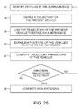
- Figure 25
- shows a flow diagram of a second method for determining an anomalous vehicle trajectory.
- In the following description, details are provided to describe the embodiments of the present specification. It shall be apparent to one skilled in the art, however, that the embodiments may be practised without such details.
-
Figure 1 shows an example of ananomalous trajectory 15 of avehicle 10 on aroad 14, which hasmarkings vehicle 10. - At a first time t0 - 8s and at a second time t0 - 7.5s the
vehicle 10 is still traveling in parallel to a left marker and to a right marker of the traffic lane, wherein "s" stands for seconds. At a time t0 - 5s the vehicle is travelling to the left of its previous position and at a later time to - 3.5 the vehicle has crossed the left marker of the right lane and is slightly overlapping with the left lane. - At a later time to - 2s the vehicle has travelled back do the right lane but is now slightly overshooting to the right with respect to its first position. At a time t0 the vehicle travels in a straight line again but now it is slightly offset to the left with respect to its first position.
- The behaviour of the
vehicle 10 is also characterized by different driving phases, such as a deviation phase ΔT1, a correction phase ΔT2, and a compensating oscillation phase ΔT3. In the example ofFig.1 , the deviation phase ΔT1 of thevehicle 10 to the left took about 2.5s, the correction phase ΔT2 and the compensating oscillation phase of the vehicle took about 2s. -
Figure 2 shows a second example of an anomalous trajectory 15' of a preceding 10 vehicle on aroad 14, which hasmarkings vehicle 10 is driving in front of apresent vehicle 9, which is driving on astraight trajectory 16. According to one method of the present specification, the anomalous trajectory 15' is detected by using the reference provided by thetraffic lanes - In the example of
Fig. 2 , the precedingvehicle 10 deviates slowly to the right, which takes about 7 seconds in total. A drifting off to the right takes about 5 seconds and a corrective movement to the left takes about 3 seconds. This time, there are no subsequent oscillations after the vehicle has come back to its previous position. Hence, there is a deviation phase of about 5 seconds and a correction phase of about 3 seconds. - In the example of
Fig. 2 , the precedingvehicle 10 already leaves the lane, drives on the marginal strip and is coming dangerously close to veering off the road. This is a further indicator of an unintended motion. Sometimes, the marginal strip has a rough material or loose chippings and this might also affect the reactions of the precedingdriver 10. - The distances and relative velocities of the vehicle in front at the times t0 - 8s, t0 - 7s, t0 - 6s, t0 - 5s, t0 - 4s, t0 - 3s, t0 - 2s, t0 - 1s, t0 with respect to the present vehicle are summarized in the following Table 1:
Time Distance Relative transverse speed ΔVy t0 - 8s 0.1m -0.1 m/s t0 - 7s 0.3m -0.2 m/s t0 - 6s 0.55m -0.25 m/s t0 - 5s 0.85m -0.3 m/s t0 - 4s 1.2m -0.35 m/s t0 - 3s 1.3m -0.1 m/s t0 - 2s 1.1m 0.3 m/s t0 - 1s 0.4m 0.7 m/s t0 0m 0.4 m/s -
Fig. 3 shows apresent vehicle 9 and a precedingvehicle 10 which are travelling on the same trajectories as shown inFig. 2 . Different fromFig. 3 , there are no road markings, or at least the road marking are not sufficiently clear for determining a trajectory of the precedingvehicle 10. -
Fig. 4 shows apresent vehicle 9 and a precedingvehicle 10 on a road 14', which are moving on the same trajectories as shown inFig. 3 . Furthermore,Fig. 4 shows a following or trailingvehicle 8, which travels behind thepresent vehicle 9 in a similar trajectory as thepresent vehicle 9. For simplicity, the trajectory of the followingvehicle 8 is not shown in detail. -
Fig. 5 shows apresent vehicle 9, a precedingvehicle 10 and aleft side vehicle 7 on adouble road 17 with afirst track 14" and asecond track 24, which are separated by amedian strip 25. - The preceding
vehicle 10 and thepresent vehicle 9 are moving on the same trajectories as shown inFig. 3 and in Table 1. Theleft side vehicle 7 is traveling alongside thepresent vehicle 9 and is only slightly changing its relative movement. These slight changes can be summarized by the following Table 2:Time Lateral deviation Relative transverse speed ΔVy t0 - 8s 0.3m 0.1 m/s t0 - 7s 0.4m 0.1 m/s t0 - 6s 0.5m 0.1 m/s t0 - 5s 0.5m 0.05 m/s t0 - 4s 0.55m 0 m/s t0 - 3s 0.45m -0.1 m/s t0 - 2s 0.35m 0.1 m/s t0 - 1s 0.25m 0.1 m/s t0 0.15m -0.1 m/s - In the examples of
Fig. 1, 2 and5 , the relative transverse speed is determined with respect to the markers, whereas in the examples ofFig. 3 and 4 it is determined with respect to a trajectory of thepresent vehicle 9. - The trajectory of the
present vehicle 9 can be determined by using the signals of steering angle and speed sensors of the present vehicle and/or by using an ego-motion calculation of a camera system of thepresent vehicle 9 or also by using a GPS system of thepresent vehicle 9. -
Figs. 6 to 14 show the motion ofFig. 2 of the precedingvehicle 10 from the perspective of a mono camera of thepresent vehicle 9. Distancemarkers velocity arrow 28 next to avertical symmetry axis 29 of the precedingcar 10 indicates the lateral speed of the preceding vehicle. Furthermore, a vertical line 30 indicates adistance 31 from the middle 32 of the lane to thevertical symmetry axis 29 of the precedingcar 10. - The respective distances of the respective lateral boundaries of the preceding vehicle to the lane markings are calculated as in the following Table 3:
Time Distance to left lane marking Distance to right lane marking t0 55cm 55cm t0 - 1s 99cm 15cm t0 - 2s 175cm Not calculated t0 - 3s 185cm Not calculated t0 - 4s 175cm Not calculated t0 - 5s 140 cm Not calculated t0 - 6s 110cm Not calculated t0 - 7s 85cm 15cm t0 - 8s 65cm 45cm - In the embodiment of
Figs. 6 to 14 , the distance of a lateral boundary of the precedingvehicle 10 to a lane marking 11, 12, 13 is not calculated if the respective boundary is outside the boundaries of the lanes. Especially when the lateral boundary is determined by a boundary of the tires, as inFigs. 6 to 14 , this distance is more difficult to calculate and may not be useful for improving the estimate. However, in other embodiments, the lateral distance may be calculated for this case as well. -
Figs. 15 to 23 show a preceding vehicle traveling on the trajectory ofFig. 3 from the perspective of a mono camera of thepresent vehicle 9. A distance marker 31' indicates a distance from a current heading 33 of thepresent vehicle 9 to asymmetry axis 29. More specifically, thevertical line 33 represents a projection of the current heading to the street surface. - The
symmetry axis 29 can be determined, for example, by first determining the lateral boundaries of the precedingvehicle 10 and calculating a centre point between the lateral boundaries. - A
velocity arrow 28 next to a vertical symmetry axis of the precedingcar 10 indicates the lateral speed of the precedingvehicle 10. Furthermore, avertical line 33 indicates a distance from the current heading 33 to the lane to thevertical symmetry axis 29 of the precedingcar 10. - For the purpose of illustration,
Figs. 2 to 23 refer to time slots of 1 second or 0.5 seconds. In an actual implementation, the time slots can be shorter or longer. For example, for a vehicle camera with 15 frames per second or 30 frames per second, the times slots can be as short as 1/15 or 1/30 of a second. - According to a first method, which is used when the markings of the traffic lanes can be identified by the ADAS camera sensors or other sensors in the vehicle. The markings are used as reference to establish whether a vehicle in the vicinity is drifting from its traffic lane in a hazardous way.
- According to a second method, which is used when there are no markings or the when vehicle cannot identify the markings of the traffic lanes with sufficient accuracy. The own trajectory and, if possible, the additional trajectories of the other vehicles in the vicinity are used as reference to establish whether a vehicle is drifting from its traffic lane in a hazardous way.
- The first method is now explained in further detail. In a
first step 40, the system identifies the traffic lanes and markings of the traffic lanes. - In a
step 41, the lanes are used to establish a reference. The reference could be for example the longitudinal axes of the traffic lane. Another way is to use one of the left or the right boundary lines of the traffic lane as reference. - For the lane in front of the vehicle, the lane detection can be done using existing ADAS Front camera sensors that are also used for a lane detection (LD) function.
- For the rear side of the present car, a rear view camera can be used. According to one embodiment, a computation unit of the rear view camera is operative to execute methods for detecting the traffic lines.
- A surround view camera that is operative to execute method for line detection can also be used for detecting the lines of the left side traffic lane or right side traffic lane. The surround view can be used in place of a rear view camera.
- In a
second step 42, the system identifies the vehicles in the surrounding area of thepresent vehicle 9. This action is done based on the existing algorithms for object detection and object classification that are integrated in the ADAS sensors, such camera sensors, radar, lidar etc. - In a
third step 43, the system establishes the actual precise position of the discovered vehicles within the vicinity relative to their traffic lanes or, in other words, relative to the reference that has been chosen based on the markings of the traffic lanes. - For example for the preceding vehicles the images from the front view camera can be used to calculate the lateral deviations relative to their references.
- When the longitudinal distance between the present vehicle and the other neighbouring vehicles is needed, it can be calculated using the images from the camera sensors but it can also be taken from ADAS Radar and Lidar sensors. The system records these parameters for further calculations.
- In a
fourth step 44, the system calculates several parameters for each vehicle within the vicinity like the transverse speed and the lateral deviation versus its reference and the trajectory that the vehicle has followed in a certain period of time until the present moment. - Additional parameters can be also used, such as: the longitudinal speed, the distance covered along the traffic lane from a previous calculation time step, etc. The speed values are calculated taking in consideration the successive positions of the vehicle.
- In a
fifth step 45, a decision is taken with respect to the trajectory for each vehicle within the surrounding area. The decision is used to establish if the vehicle has a normal or non-dangerous trajectory or if the vehicle is drifting on a hazardous trajectory. If an anomalous trajectory is detected, an alert signal is generated and output for further processing. The generated alert signal can also include a confidence value, which indicates a certainty that the trajectory is an anomalous trajectory, or a risk value, which indicates a risk caused by the anomalous trajectory. - For the decision, the system uses also additional information for each vehicle that is monitored. For example, the activation of the turn indicators or of the brake lamps, etc. Such information is taken in consideration for the decision whether the trajectory is a normal one or a hazardous one. Turning vehicle lights on or off or activation of the brakes, which is also indicated by the braking lights, indicates that the driver of the vehicle intends to drive the vehicle in that way.
- A decision whether a vehicle trajectory is an anomalous trajectory can be derived in several ways.
- One way is based on a comparison with a pattern of trajectories. A classification table can be used to this end. The classification table contains a number of pre-determined patterns of trajectories, which have been chosen based on the detailed studies of the vehicle dynamics in traffic. The table is specific for a given position of the vehicles relative to the present vehicle. The classification table contains normal trajectories and anomalous trajectories for the monitored vehicle, including the hazardous ones.
- Another way to decide whether a vehicle moves normally along its traffic lane is based on the parameters of its trajectory, such as
- the transverse speed of the vehicle at successive moments in time in which the vehicle deviates from the ideal trajectory on the traffic lane without having the turn indicator activated.
- the value of the lateral deviation from the reference.
- the transverse speed of the vehicle when the driver corrects the trajectory versus the reference. When a driver suffers of fatigue and is close to fall asleep the vehicle deviates slowly from its trajectory from the traffic lane. When he realise the deviation, it is highly likely that he corrects the trajectory abruptly.
- the number of deviations from the ideal trajectory in a certain time frame. Very often, a sleepy driver causes the vehicle to deviate repetitively or repeatedly, not only once. Therefore, the number of deviations in a given time provides an indication for the nature of the observed vehicle trajectory.
- According to a second method, which is used if the vehicle is not able to find useful markings on the traffic lines, the position of a close-by vehicle is determined with respect to the longitudinal axes of the trajectory of the present vehicle, which are used as a reference. The close-by or neighbouring vehicle is situated within a surrounding area of the present vehicle.
- If further data from imaging or distance sensors are available, this trajectory is confirmed by the trajectories of the other vehicles situated in the field of view of the sensors, such as camera, radar or lidar.
- In a
first step 47 of the second method, the system identifies the vehicles in the surrounding area of the vehicle. This action is similar to thesecond step 42 of the first method. In astep 48, the system derives a trajectory of thepresent vehicle 9. In astep 49, the system uses the derived trajectory of the present vehicle to establish a reference. - In a
second step 43' of the second method, which is similar to the third step of the first method, the system establishes the actual precise position of the discovered vehicles within the vicinity relative to the longitudinal axis of the own vehicle. For example, for the precedingvehicles 10 the images from the front view camera can be used to calculate the lateral deviations relative to the reference. - If the longitudinal distance between the
present vehicle 10 and the other neighbour vehicles is required, it can be calculated using the images from the camera sensors but it can also be taken from ADAS Radar and Lidar sensors. The system will record these parameters for further calculations. - A third step 44' of the second method is similar to the fourth step 44' of the first method. The system calculates several parameters for each vehicle within the vicinity of the present vehicle, such as the transverse speed or the lateral deviation versus the longitudinal axis of the present vehicle's trajectory. The system also calculates the trajectory that the vehicle has followed in a certain period of time until the present moment.
- Additional parameters can be also be used, such as the longitudinal speed or the distance covered along the traffic lane from a previous calculation time step. The values for the lateral and longitudinal positions of the neighbouring vehicles are determined relative to the longitudinal axis of the trajectory of the present vehicle.
- The values for the transverse or longitudinal speeds are calculated taking into consideration the actual and the previous positions of the vehicles.
- The
fifth step 45 is a decision step, in which a decision is taken with respect to the nature of the trajectory for each vehicle within the surrounding area. In particular, the decision establishes if the vehicle has a normal or non-dangerous trajectory or, instead, if the vehicle is drifting on a hazardous trajectory. - Similar to the first method, the system can make use of additional information that is monitored for the vehicles. For example, the activation of the turning indicators or the brake lamps, etc.
- If an anomalous trajectory is detected, an alert signal is generated in a
step 46 and output for further processing. - Although the above description contains much specificity, these should not be construed as limiting the scope of the embodiments but merely providing illustration of the foreseeable embodiments. Especially the above stated advantages of the embodiments should not be construed as limiting the scope of the embodiments but merely to explain possible achievements if the described embodiments are put into practise. Thus, the scope of the embodiments should be determined by the claims and their equivalents, rather than by the examples given.
Claims (15)
- Method for determining an anomalous driving pattern of a neighbouring vehicle with a vehicle camera of a present vehicle, comprising- receiving image data from the vehicle camera, the image data comprising image frames,- scanning the image data for lane markings and lane boundaries,
if lane markings are detected in the image frames
determining if the detected lane markings are suitable for deriving a trajectory of the neighbouring vehicle relative to the lane markings and, if it is determined that the detected lane markings are suitable,
deriving a reference trajectory from the detected lane markings,
else
deriving a reference trajectory from a motion of the present vehicle,
determining a trajectory of the neighbouring vehicle relative to the reference trajectory,
deriving characteristic parameters of the determined trajectory,
comparing the characteristic parameters with predetermined trajectory data,
determining, based on the comparison, if the trajectory of the neighbouring vehicle is an anomalous trajectory, outputting an alert signal if it is determined that the trajectory of the neighbouring vehicle is an anomalous trajectory. - Method according to claim 1, wherein the predetermined trajectory data comprise a deviation to the left or to the right with respect to the reference trajectory.
- Method according to claim 1 or claim 2, wherein the pre-determined trajectory data comprise a deviation pattern with respect to a reference trajectory.
- Method according to claim 3, wherein the deviation pattern is a deviation time sequence with respect to a reference trajectory.
- Method according to claim 3 or claim 4, wherein the deviation pattern comprises a first lateral deviation in a first direction and a subsequent second lateral deviation in a second direction, wherein the second direction is opposite to the first direction.
- Method according to claim 5, wherein a duration of the second lateral deviation is shorter than a duration of the first lateral deviation.
- Method according to one of the claims 2 to 6, wherein the reference trajectory is derived from an image sequence of a lane marking.
- Method according to one of the claims 2 to 6, wherein the reference trajectory is derived from motion sensor data of the present vehicle.
- Method according to one of the preceding claims, wherein the neighbouring vehicle is a preceding vehicle.
- Method according to one of the preceding claims, comprising
triggering an alert action if it is determined that the trajectory of the neighbouring vehicle is an anomalous trajectory, wherein the action is selected from slowing down the present vehicle, displaying an alert message on the instrument cluster of the present vehicle, sounding an alert signal inside the present vehicle, flashing the front lights of the present vehicle, sounding the horn of the present vehicle, sending a radio message via a radio transmitter of the present vehicle and forwarding the alert message to a collision warning system. - Computer executable program code for the execution of the method according to one of the claims 1 to 10.
- Image processing unit for a vehicle, the image processing unit comprising- an input connection for receiving image data from a vehicle camera,- a computation unit which is operative to- receive image data from the vehicle camera, the image data comprising image frames,- scan the image data for lane markings and lane boundaries,- determine, if lane markings are detected in the image frames, if the detected lane markings are suitable for deriving a trajectory of the neighbouring vehicle relative to the lane markings and- derive a reference trajectory from the detected lane markings, if it is determined that the detected lane markings are suitable,- derive a reference trajectory from a motion of the present vehicle,- determine a trajectory of the neighbouring vehicles relative to the reference trajectory,- derive characteristic parameters of the determined trajectory,- compare the characteristic parameters with predetermined trajectory data,- determine, based on the comparison, if the trajectory of the neighbouring vehicle is an anomalous trajectory,- output an alert signal if it is determined that the trajectory of the neighbouring vehicle is an anomalous trajectory.
- Kit, comprising a vehicle camera and the image processing unit according to claim 12, wherein the vehicle camera is connectable to the image processing unit.
- Kit according to claim 13, wherein the image processing unit is provided within the vehicle camera.
- Vehicle comprising the kit according to claim 13 or claim 14, wherein the vehicle camera is mounted to the vehicle and pointing to the exterior of the vehicle, and wherein the processing unit is connected to the vehicle camera.
Priority Applications (4)
| Application Number | Priority Date | Filing Date | Title |
|---|---|---|---|
| EP15465539.3A EP3141926B1 (en) | 2015-09-10 | 2015-09-10 | Automated detection of hazardous drifting vehicles by vehicle sensors |
| PCT/EP2016/070652 WO2017042089A1 (en) | 2015-09-10 | 2016-09-01 | Automated detection of hazardous drifting vehicles by vehicle sensors |
| CN201680052112.9A CN108027422B (en) | 2015-09-10 | 2016-09-01 | Automatic detection of a dangerous departing vehicle by means of a vehicle sensor |
| US15/915,438 US10864911B2 (en) | 2015-09-10 | 2018-03-08 | Automated detection of hazardous drifting vehicles by vehicle sensors |
Applications Claiming Priority (1)
| Application Number | Priority Date | Filing Date | Title |
|---|---|---|---|
| EP15465539.3A EP3141926B1 (en) | 2015-09-10 | 2015-09-10 | Automated detection of hazardous drifting vehicles by vehicle sensors |
Publications (2)
| Publication Number | Publication Date |
|---|---|
| EP3141926A1 true EP3141926A1 (en) | 2017-03-15 |
| EP3141926B1 EP3141926B1 (en) | 2018-04-04 |
Family
ID=54266516
Family Applications (1)
| Application Number | Title | Priority Date | Filing Date |
|---|---|---|---|
| EP15465539.3A Active EP3141926B1 (en) | 2015-09-10 | 2015-09-10 | Automated detection of hazardous drifting vehicles by vehicle sensors |
Country Status (4)
| Country | Link |
|---|---|
| US (1) | US10864911B2 (en) |
| EP (1) | EP3141926B1 (en) |
| CN (1) | CN108027422B (en) |
| WO (1) | WO2017042089A1 (en) |
Cited By (8)
| Publication number | Priority date | Publication date | Assignee | Title |
|---|---|---|---|---|
| WO2018237018A1 (en) | 2017-06-20 | 2018-12-27 | nuTonomy Inc. | Risk processing for vehicles having autonomous driving capabilities |
| EP3566921A1 (en) * | 2017-12-27 | 2019-11-13 | The Hi-Tech Robotic Systemz Ltd | Providing relevant alerts to a driver of a vehicle |
| CN111062233A (en) * | 2018-10-17 | 2020-04-24 | 北京地平线机器人技术研发有限公司 | Marker representation acquisition method, marker representation acquisition device and electronic equipment |
| EP3690481A1 (en) * | 2019-01-30 | 2020-08-05 | Mando Corporation | Driver assistance system and control method thereof |
| US11084487B1 (en) | 2018-01-09 | 2021-08-10 | State Farm Mutual Automobile Insurance Company | Vehicle collision alert system and method for facilitating vehicle collision avoidance |
| CN114202949A (en) * | 2021-12-13 | 2022-03-18 | 大连理工大学宁波研究院 | Method for distinguishing adjacent vehicles and adjusting reference path of intelligent networked automobile on highway |
| WO2022172146A1 (en) * | 2021-02-15 | 2022-08-18 | C.R.F. Societa' Consortile Per Azioni | Automotive cooperative map-free lane-level relative localization based on inter-vehicular communication |
| CN116887257A (en) * | 2023-08-29 | 2023-10-13 | 北京友坤科技有限责任公司 | Abuse identification method and device for vehicle-to-vehicle network card, electronic equipment and storage medium |
Families Citing this family (36)
| Publication number | Priority date | Publication date | Assignee | Title |
|---|---|---|---|---|
| EP3217374A1 (en) * | 2016-03-10 | 2017-09-13 | Volvo Car Corporation | Method and system for estimating a boundary of a road technical field |
| KR102070605B1 (en) * | 2017-10-27 | 2020-03-02 | 주식회사 만도 | Autonomous emergency braking system and method by predicting circumstances surrounding vehicle |
| US10739775B2 (en) * | 2017-10-28 | 2020-08-11 | Tusimple, Inc. | System and method for real world autonomous vehicle trajectory simulation |
| US11320284B2 (en) * | 2017-12-15 | 2022-05-03 | Regents Of The University Of Minnesota | Real-time lane departure detection using map shape points and trajectory histories |
| KR102055156B1 (en) * | 2018-02-05 | 2019-12-12 | 주식회사 만도 | Control Apparatus For Smart Cruise Control System And Method Thereof |
| CN110197097B (en) * | 2018-02-24 | 2024-04-19 | 北京图森智途科技有限公司 | Harbor district monitoring method and system and central control system |
| EP3557549B1 (en) * | 2018-04-19 | 2024-02-21 | PKE Holding AG | Method for evaluating a motion event |
| DE102018109883A1 (en) * | 2018-04-24 | 2018-12-20 | Continental Teves Ag & Co. Ohg | Method and device for the cooperative tuning of future driving maneuvers of a vehicle with foreign maneuvers of at least one other vehicle |
| DE102018215509A1 (en) * | 2018-09-12 | 2020-03-12 | Robert Bosch Gmbh | Method and device for operating an at least partially automated first vehicle |
| JP7251120B2 (en) * | 2018-11-29 | 2023-04-04 | トヨタ自動車株式会社 | Information providing system, server, in-vehicle device, program and information providing method |
| FR3089925B1 (en) * | 2018-12-13 | 2020-11-20 | Psa Automobiles Sa | Safe autonomous driving in the event of detection of a target object |
| GB2579823B (en) | 2018-12-14 | 2021-08-25 | Subsea 7 Do Brasil Servicos Ltda | Incorporating structures into reeled pipelines |
| JP2020101869A (en) * | 2018-12-19 | 2020-07-02 | 本田技研工業株式会社 | Control device and program |
| EP3716245A1 (en) * | 2019-03-27 | 2020-09-30 | Zenuity AB | Method and control device for sending information to surrounding vehicles |
| CN110304064B (en) * | 2019-07-15 | 2020-09-11 | 广州小鹏汽车科技有限公司 | Control method for vehicle lane change, vehicle control system and vehicle |
| TWI705016B (en) * | 2019-07-22 | 2020-09-21 | 緯創資通股份有限公司 | Driving alarm system, driving alarm method and electronic device using the same |
| CN110608751A (en) * | 2019-08-14 | 2019-12-24 | 广汽蔚来新能源汽车科技有限公司 | Driving navigation method and device, vehicle-mounted computer equipment and storage medium |
| DE102019220223A1 (en) * | 2019-12-19 | 2021-06-24 | Robert Bosch Gmbh | Method for operating a sensor of a motor vehicle |
| FR3106108A1 (en) * | 2020-01-14 | 2021-07-16 | Psa Automobiles Sa | Method and device for determining the trajectory of a road |
| CN113276765A (en) * | 2020-01-31 | 2021-08-20 | 神达数位股份有限公司 | Driving warning method and system and computer program product |
| US11364883B2 (en) * | 2020-03-27 | 2022-06-21 | Nvidia Corporation | Leveraging rear-view sensors for automatic emergency braking in autonomous machine applications |
| KR20220036423A (en) * | 2020-09-15 | 2022-03-23 | 현대자동차주식회사 | Vehicle and method of controlling autonomous driving for the same |
| US11618444B2 (en) * | 2020-10-01 | 2023-04-04 | Argo AI, LLC | Methods and systems for autonomous vehicle inference of routes for actors exhibiting unrecognized behavior |
| US11731661B2 (en) | 2020-10-01 | 2023-08-22 | Argo AI, LLC | Systems and methods for imminent collision avoidance |
| US11358598B2 (en) | 2020-10-01 | 2022-06-14 | Argo AI, LLC | Methods and systems for performing outlet inference by an autonomous vehicle to determine feasible paths through an intersection |
| CN112633124A (en) * | 2020-12-17 | 2021-04-09 | 东风汽车有限公司 | Target vehicle judgment method for automatic driving vehicle and electronic equipment |
| CN112937572A (en) * | 2021-02-01 | 2021-06-11 | 邵阳学院 | Method, device and system for preventing and controlling dangerous behaviors of vehicle and storage medium |
| US20220315047A1 (en) * | 2021-03-30 | 2022-10-06 | Honda Research Institute Europe Gmbh | Method, system and vehicle with an uncertainty-based lane positioning control |
| DE102021205200B4 (en) | 2021-05-20 | 2023-07-06 | Volkswagen Aktiengesellschaft | Method for operating a driver assistance system of a vehicle and vehicle |
| CN113433548B (en) * | 2021-06-24 | 2023-02-28 | 中国第一汽车股份有限公司 | Data monitoring method, device, equipment and storage medium |
| US20220028258A1 (en) * | 2021-07-14 | 2022-01-27 | Nec Corporation | Warning presentation control device, warning presentation control system, method of controlling warning presentation, and recording medium storing warning presentation control program |
| CN114023109B (en) * | 2021-11-03 | 2023-06-30 | 中国矿业大学 | Early warning system for preventing rear-end collision of mobile tank truck |
| CN114506344B (en) * | 2022-03-10 | 2024-03-08 | 福瑞泰克智能系统有限公司 | Method and device for determining vehicle track |
| FR3140603A1 (en) * | 2022-10-10 | 2024-04-12 | Renault S.A.S. | Method of alerting the driver of a vehicle |
| EP4357812A1 (en) * | 2022-10-19 | 2024-04-24 | Continental Autonomous Mobility Germany GmbH | Vehicle detection system and method for detecting a target vehicle in a detection area located behind a subject vehicle |
| CN117494029B (en) * | 2023-12-29 | 2024-04-19 | 苏州映赛智能科技有限公司 | Road casting event identification method and device |
Citations (4)
| Publication number | Priority date | Publication date | Assignee | Title |
|---|---|---|---|---|
| EP1065520A2 (en) * | 1999-06-28 | 2001-01-03 | Hitachi, Ltd. | Vehicle control method and vehicle warning method |
| EP1354767A2 (en) * | 2002-04-16 | 2003-10-22 | Fuji Jukogyo Kabushiki Kaisha | Vehicle surroundings monitoring apparatus and vehicle traveling control system incorporating the apparatus |
| EP2012211A1 (en) * | 2007-07-03 | 2009-01-07 | Ford Global Technologies, LLC | A system for monitoring the surroundings of a vehicle |
| EP2169427A1 (en) * | 2008-09-24 | 2010-03-31 | Delphi Technologies, Inc. | Method of probabilistic lane assignment with radar system, vision system, yaw-rate sensor and speed-sensor |
Family Cites Families (7)
| Publication number | Priority date | Publication date | Assignee | Title |
|---|---|---|---|---|
| US8825378B2 (en) * | 2013-01-25 | 2014-09-02 | Nissan North America, Inc. | Vehicle drift determination apparatus and method |
| EP2778007B1 (en) * | 2013-03-12 | 2022-09-07 | INRIA - Institut National de Recherche en Informatique et en Automatique | Method and system to assess abnormal driving behaviour of vehicles travelling on road |
| US9147353B1 (en) * | 2013-05-29 | 2015-09-29 | Allstate Insurance Company | Driving analysis using vehicle-to-vehicle communication |
| CN103395391B (en) * | 2013-07-03 | 2015-08-05 | 北京航空航天大学 | A kind of vehicle lane-changing alarming device and change state identification method |
| KR101541483B1 (en) * | 2014-01-03 | 2015-08-03 | 현대모비스(주) | System for monitoring change of a traffic lane andcontrol method thereof |
| WO2015155833A1 (en) * | 2014-04-08 | 2015-10-15 | 三菱電機株式会社 | Collision prevention device |
| US9868443B2 (en) * | 2015-04-27 | 2018-01-16 | GM Global Technology Operations LLC | Reactive path planning for autonomous driving |
-
2015
- 2015-09-10 EP EP15465539.3A patent/EP3141926B1/en active Active
-
2016
- 2016-09-01 WO PCT/EP2016/070652 patent/WO2017042089A1/en active Application Filing
- 2016-09-01 CN CN201680052112.9A patent/CN108027422B/en active Active
-
2018
- 2018-03-08 US US15/915,438 patent/US10864911B2/en active Active
Patent Citations (4)
| Publication number | Priority date | Publication date | Assignee | Title |
|---|---|---|---|---|
| EP1065520A2 (en) * | 1999-06-28 | 2001-01-03 | Hitachi, Ltd. | Vehicle control method and vehicle warning method |
| EP1354767A2 (en) * | 2002-04-16 | 2003-10-22 | Fuji Jukogyo Kabushiki Kaisha | Vehicle surroundings monitoring apparatus and vehicle traveling control system incorporating the apparatus |
| EP2012211A1 (en) * | 2007-07-03 | 2009-01-07 | Ford Global Technologies, LLC | A system for monitoring the surroundings of a vehicle |
| EP2169427A1 (en) * | 2008-09-24 | 2010-03-31 | Delphi Technologies, Inc. | Method of probabilistic lane assignment with radar system, vision system, yaw-rate sensor and speed-sensor |
Cited By (19)
| Publication number | Priority date | Publication date | Assignee | Title |
|---|---|---|---|---|
| KR20220050233A (en) * | 2017-06-20 | 2022-04-22 | 모셔널 에이디 엘엘씨 | Risk processing for vehicles having autonomous driving capabilities |
| KR20200019696A (en) * | 2017-06-20 | 2020-02-24 | 누토노미 인크. | Risk handling for vehicles with autonomous driving capabilities |
| CN110997387A (en) * | 2017-06-20 | 2020-04-10 | 优特诺股份有限公司 | Risk handling for vehicles with autonomous driving capability |
| WO2018237018A1 (en) | 2017-06-20 | 2018-12-27 | nuTonomy Inc. | Risk processing for vehicles having autonomous driving capabilities |
| US11897460B2 (en) | 2017-06-20 | 2024-02-13 | Motional Ad Llc | Risk processing for vehicles having autonomous driving capabilities |
| EP3642068A4 (en) * | 2017-06-20 | 2020-10-21 | nuTonomy Inc. | Risk processing for vehicles having autonomous driving capabilities |
| US11008000B2 (en) | 2017-06-20 | 2021-05-18 | Motional Ad Llc | Risk processing for vehicles having autonomous driving capabilities |
| EP3566921A1 (en) * | 2017-12-27 | 2019-11-13 | The Hi-Tech Robotic Systemz Ltd | Providing relevant alerts to a driver of a vehicle |
| US11084487B1 (en) | 2018-01-09 | 2021-08-10 | State Farm Mutual Automobile Insurance Company | Vehicle collision alert system and method for facilitating vehicle collision avoidance |
| US11574544B1 (en) | 2018-01-09 | 2023-02-07 | State Farm Mutual Automobile Insurance Company | Vehicle collision alert system and method |
| US11557207B1 (en) | 2018-01-09 | 2023-01-17 | State Farm Mutual Automobile Insurance Company | Vehicle collision alert system and method for detecting driving hazards |
| CN111062233A (en) * | 2018-10-17 | 2020-04-24 | 北京地平线机器人技术研发有限公司 | Marker representation acquisition method, marker representation acquisition device and electronic equipment |
| US11299147B2 (en) | 2019-01-30 | 2022-04-12 | Mando Mobility Solutions Corporation | Driver assistance system and control method thereof |
| EP3690481A1 (en) * | 2019-01-30 | 2020-08-05 | Mando Corporation | Driver assistance system and control method thereof |
| WO2022172146A1 (en) * | 2021-02-15 | 2022-08-18 | C.R.F. Societa' Consortile Per Azioni | Automotive cooperative map-free lane-level relative localization based on inter-vehicular communication |
| CN114202949A (en) * | 2021-12-13 | 2022-03-18 | 大连理工大学宁波研究院 | Method for distinguishing adjacent vehicles and adjusting reference path of intelligent networked automobile on highway |
| CN114202949B (en) * | 2021-12-13 | 2024-04-12 | 大连理工大学宁波研究院 | Method for identifying adjacent vehicles and adjusting reference paths of expressway intelligent network-connected automobile |
| CN116887257A (en) * | 2023-08-29 | 2023-10-13 | 北京友坤科技有限责任公司 | Abuse identification method and device for vehicle-to-vehicle network card, electronic equipment and storage medium |
| CN116887257B (en) * | 2023-08-29 | 2023-11-28 | 北京友坤科技有限责任公司 | Abuse identification method and device for vehicle-to-vehicle network card, electronic equipment and storage medium |
Also Published As
| Publication number | Publication date |
|---|---|
| US10864911B2 (en) | 2020-12-15 |
| CN108027422A (en) | 2018-05-11 |
| EP3141926B1 (en) | 2018-04-04 |
| US20180257647A1 (en) | 2018-09-13 |
| WO2017042089A1 (en) | 2017-03-16 |
| CN108027422B (en) | 2023-04-14 |
Similar Documents
| Publication | Publication Date | Title |
|---|---|---|
| EP3141926B1 (en) | Automated detection of hazardous drifting vehicles by vehicle sensors | |
| KR101996419B1 (en) | Sensor integration based pedestrian detection and pedestrian collision prevention apparatus and method | |
| US10710580B2 (en) | Tailgating situation handling by an automated driving vehicle | |
| JP5345350B2 (en) | Vehicle driving support device | |
| EP3086990B1 (en) | Method and system for driver assistance for a vehicle | |
| US9896129B2 (en) | Driving assistant system of vehicle and method for controlling the same | |
| US9223311B2 (en) | Vehicle driving support control apparatus | |
| US9091558B2 (en) | Autonomous driver assistance system and autonomous driving method thereof | |
| KR20200102004A (en) | Apparatus, system and method for preventing collision | |
| CN109204311B (en) | Automobile speed control method and device | |
| US20140044311A1 (en) | Neighboring vehicle detecting apparatus | |
| JP6354659B2 (en) | Driving support device | |
| US10930153B2 (en) | Vehicle external notification device | |
| JP6323064B2 (en) | Traveling lane identification device, lane change support device, traveling lane identification method | |
| CN107408346B (en) | Vehicle control device and vehicle control method | |
| KR20170070213A (en) | Lane assistance system responsive to extremely fast approaching vehicles | |
| JP2007072641A (en) | Dangerous vehicle detection device | |
| JP2012089114A (en) | Obstacle recognition device | |
| JP4876772B2 (en) | Interrupting vehicle determination device | |
| JP2010092416A (en) | Device for preventing lane deviation | |
| JP2018097765A (en) | Object detection device and object detection method | |
| JP5233696B2 (en) | Lane boundary detection device, boundary detection program, and departure warning device | |
| JP2020134981A (en) | Driving assistance device | |
| JP2008040819A (en) | Obstacle recognition device | |
| JP6520691B2 (en) | Lane deviation warning device and lane deviation warning method |
Legal Events
| Date | Code | Title | Description |
|---|---|---|---|
| PUAI | Public reference made under article 153(3) epc to a published international application that has entered the european phase |
Free format text: ORIGINAL CODE: 0009012 |
|
| AK | Designated contracting states |
Kind code of ref document: A1 Designated state(s): AL AT BE BG CH CY CZ DE DK EE ES FI FR GB GR HR HU IE IS IT LI LT LU LV MC MK MT NL NO PL PT RO RS SE SI SK SM TR |
|
| AX | Request for extension of the european patent |
Extension state: BA ME |
|
| 17P | Request for examination filed |
Effective date: 20170915 |
|
| RBV | Designated contracting states (corrected) |
Designated state(s): AL AT BE BG CH CY CZ DE DK EE ES FI FR GB GR HR HU IE IS IT LI LT LU LV MC MK MT NL NO PL PT RO RS SE SI SK SM TR |
|
| GRAP | Despatch of communication of intention to grant a patent |
Free format text: ORIGINAL CODE: EPIDOSNIGR1 |
|
| RIC1 | Information provided on ipc code assigned before grant |
Ipc: G06K 9/00 20060101ALI20171019BHEP Ipc: G01S 13/93 20060101ALI20171019BHEP Ipc: G01S 13/86 20060101ALN20171019BHEP Ipc: G01S 7/41 20060101AFI20171019BHEP |
|
| INTG | Intention to grant announced |
Effective date: 20171114 |
|
| GRAS | Grant fee paid |
Free format text: ORIGINAL CODE: EPIDOSNIGR3 |
|
| GRAA | (expected) grant |
Free format text: ORIGINAL CODE: 0009210 |
|
| AK | Designated contracting states |
Kind code of ref document: B1 Designated state(s): AL AT BE BG CH CY CZ DE DK EE ES FI FR GB GR HR HU IE IS IT LI LT LU LV MC MK MT NL NO PL PT RO RS SE SI SK SM TR |
|
| REG | Reference to a national code |
Ref country code: GB Ref legal event code: FG4D |
|
| REG | Reference to a national code |
Ref country code: CH Ref legal event code: EP |
|
| REG | Reference to a national code |
Ref country code: AT Ref legal event code: REF Ref document number: 986162 Country of ref document: AT Kind code of ref document: T Effective date: 20180415 |
|
| REG | Reference to a national code |
Ref country code: IE Ref legal event code: FG4D |
|
| REG | Reference to a national code |
Ref country code: DE Ref legal event code: R096 Ref document number: 602015009529 Country of ref document: DE |
|
| REG | Reference to a national code |
Ref country code: NL Ref legal event code: MP Effective date: 20180404 |
|
| REG | Reference to a national code |
Ref country code: LT Ref legal event code: MG4D |
|
| REG | Reference to a national code |
Ref country code: FR Ref legal event code: PLFP Year of fee payment: 4 |
|
| PG25 | Lapsed in a contracting state [announced via postgrant information from national office to epo] |
Ref country code: NL Free format text: LAPSE BECAUSE OF FAILURE TO SUBMIT A TRANSLATION OF THE DESCRIPTION OR TO PAY THE FEE WITHIN THE PRESCRIBED TIME-LIMIT Effective date: 20180404 |
|
| PG25 | Lapsed in a contracting state [announced via postgrant information from national office to epo] |
Ref country code: BG Free format text: LAPSE BECAUSE OF FAILURE TO SUBMIT A TRANSLATION OF THE DESCRIPTION OR TO PAY THE FEE WITHIN THE PRESCRIBED TIME-LIMIT Effective date: 20180704 Ref country code: NO Free format text: LAPSE BECAUSE OF FAILURE TO SUBMIT A TRANSLATION OF THE DESCRIPTION OR TO PAY THE FEE WITHIN THE PRESCRIBED TIME-LIMIT Effective date: 20180704 Ref country code: AL Free format text: LAPSE BECAUSE OF FAILURE TO SUBMIT A TRANSLATION OF THE DESCRIPTION OR TO PAY THE FEE WITHIN THE PRESCRIBED TIME-LIMIT Effective date: 20180404 Ref country code: FI Free format text: LAPSE BECAUSE OF FAILURE TO SUBMIT A TRANSLATION OF THE DESCRIPTION OR TO PAY THE FEE WITHIN THE PRESCRIBED TIME-LIMIT Effective date: 20180404 Ref country code: SE Free format text: LAPSE BECAUSE OF FAILURE TO SUBMIT A TRANSLATION OF THE DESCRIPTION OR TO PAY THE FEE WITHIN THE PRESCRIBED TIME-LIMIT Effective date: 20180404 Ref country code: LT Free format text: LAPSE BECAUSE OF FAILURE TO SUBMIT A TRANSLATION OF THE DESCRIPTION OR TO PAY THE FEE WITHIN THE PRESCRIBED TIME-LIMIT Effective date: 20180404 Ref country code: PL Free format text: LAPSE BECAUSE OF FAILURE TO SUBMIT A TRANSLATION OF THE DESCRIPTION OR TO PAY THE FEE WITHIN THE PRESCRIBED TIME-LIMIT Effective date: 20180404 Ref country code: ES Free format text: LAPSE BECAUSE OF FAILURE TO SUBMIT A TRANSLATION OF THE DESCRIPTION OR TO PAY THE FEE WITHIN THE PRESCRIBED TIME-LIMIT Effective date: 20180404 |
|
| PG25 | Lapsed in a contracting state [announced via postgrant information from national office to epo] |
Ref country code: HR Free format text: LAPSE BECAUSE OF FAILURE TO SUBMIT A TRANSLATION OF THE DESCRIPTION OR TO PAY THE FEE WITHIN THE PRESCRIBED TIME-LIMIT Effective date: 20180404 Ref country code: RS Free format text: LAPSE BECAUSE OF FAILURE TO SUBMIT A TRANSLATION OF THE DESCRIPTION OR TO PAY THE FEE WITHIN THE PRESCRIBED TIME-LIMIT Effective date: 20180404 Ref country code: GR Free format text: LAPSE BECAUSE OF FAILURE TO SUBMIT A TRANSLATION OF THE DESCRIPTION OR TO PAY THE FEE WITHIN THE PRESCRIBED TIME-LIMIT Effective date: 20180705 Ref country code: LV Free format text: LAPSE BECAUSE OF FAILURE TO SUBMIT A TRANSLATION OF THE DESCRIPTION OR TO PAY THE FEE WITHIN THE PRESCRIBED TIME-LIMIT Effective date: 20180404 |
|
| REG | Reference to a national code |
Ref country code: AT Ref legal event code: MK05 Ref document number: 986162 Country of ref document: AT Kind code of ref document: T Effective date: 20180404 |
|
| PG25 | Lapsed in a contracting state [announced via postgrant information from national office to epo] |
Ref country code: PT Free format text: LAPSE BECAUSE OF FAILURE TO SUBMIT A TRANSLATION OF THE DESCRIPTION OR TO PAY THE FEE WITHIN THE PRESCRIBED TIME-LIMIT Effective date: 20180806 |
|
| REG | Reference to a national code |
Ref country code: DE Ref legal event code: R097 Ref document number: 602015009529 Country of ref document: DE |
|
| PG25 | Lapsed in a contracting state [announced via postgrant information from national office to epo] |
Ref country code: SK Free format text: LAPSE BECAUSE OF FAILURE TO SUBMIT A TRANSLATION OF THE DESCRIPTION OR TO PAY THE FEE WITHIN THE PRESCRIBED TIME-LIMIT Effective date: 20180404 Ref country code: RO Free format text: LAPSE BECAUSE OF FAILURE TO SUBMIT A TRANSLATION OF THE DESCRIPTION OR TO PAY THE FEE WITHIN THE PRESCRIBED TIME-LIMIT Effective date: 20180404 Ref country code: CZ Free format text: LAPSE BECAUSE OF FAILURE TO SUBMIT A TRANSLATION OF THE DESCRIPTION OR TO PAY THE FEE WITHIN THE PRESCRIBED TIME-LIMIT Effective date: 20180404 Ref country code: DK Free format text: LAPSE BECAUSE OF FAILURE TO SUBMIT A TRANSLATION OF THE DESCRIPTION OR TO PAY THE FEE WITHIN THE PRESCRIBED TIME-LIMIT Effective date: 20180404 Ref country code: AT Free format text: LAPSE BECAUSE OF FAILURE TO SUBMIT A TRANSLATION OF THE DESCRIPTION OR TO PAY THE FEE WITHIN THE PRESCRIBED TIME-LIMIT Effective date: 20180404 Ref country code: EE Free format text: LAPSE BECAUSE OF FAILURE TO SUBMIT A TRANSLATION OF THE DESCRIPTION OR TO PAY THE FEE WITHIN THE PRESCRIBED TIME-LIMIT Effective date: 20180404 |
|
| PLBE | No opposition filed within time limit |
Free format text: ORIGINAL CODE: 0009261 |
|
| STAA | Information on the status of an ep patent application or granted ep patent |
Free format text: STATUS: NO OPPOSITION FILED WITHIN TIME LIMIT |
|
| PG25 | Lapsed in a contracting state [announced via postgrant information from national office to epo] |
Ref country code: SM Free format text: LAPSE BECAUSE OF FAILURE TO SUBMIT A TRANSLATION OF THE DESCRIPTION OR TO PAY THE FEE WITHIN THE PRESCRIBED TIME-LIMIT Effective date: 20180404 Ref country code: IT Free format text: LAPSE BECAUSE OF FAILURE TO SUBMIT A TRANSLATION OF THE DESCRIPTION OR TO PAY THE FEE WITHIN THE PRESCRIBED TIME-LIMIT Effective date: 20180404 |
|
| 26N | No opposition filed |
Effective date: 20190107 |
|
| PG25 | Lapsed in a contracting state [announced via postgrant information from national office to epo] |
Ref country code: MC Free format text: LAPSE BECAUSE OF FAILURE TO SUBMIT A TRANSLATION OF THE DESCRIPTION OR TO PAY THE FEE WITHIN THE PRESCRIBED TIME-LIMIT Effective date: 20180404 |
|
| REG | Reference to a national code |
Ref country code: CH Ref legal event code: PL |
|
| PG25 | Lapsed in a contracting state [announced via postgrant information from national office to epo] |
Ref country code: SI Free format text: LAPSE BECAUSE OF FAILURE TO SUBMIT A TRANSLATION OF THE DESCRIPTION OR TO PAY THE FEE WITHIN THE PRESCRIBED TIME-LIMIT Effective date: 20180404 |
|
| REG | Reference to a national code |
Ref country code: BE Ref legal event code: MM Effective date: 20180930 |
|
| REG | Reference to a national code |
Ref country code: IE Ref legal event code: MM4A |
|
| PG25 | Lapsed in a contracting state [announced via postgrant information from national office to epo] |
Ref country code: LU Free format text: LAPSE BECAUSE OF NON-PAYMENT OF DUE FEES Effective date: 20180910 |
|
| PG25 | Lapsed in a contracting state [announced via postgrant information from national office to epo] |
Ref country code: IE Free format text: LAPSE BECAUSE OF NON-PAYMENT OF DUE FEES Effective date: 20180910 |
|
| PG25 | Lapsed in a contracting state [announced via postgrant information from national office to epo] |
Ref country code: LI Free format text: LAPSE BECAUSE OF NON-PAYMENT OF DUE FEES Effective date: 20180930 Ref country code: BE Free format text: LAPSE BECAUSE OF NON-PAYMENT OF DUE FEES Effective date: 20180930 Ref country code: CH Free format text: LAPSE BECAUSE OF NON-PAYMENT OF DUE FEES Effective date: 20180930 |
|
| PG25 | Lapsed in a contracting state [announced via postgrant information from national office to epo] |
Ref country code: MT Free format text: LAPSE BECAUSE OF NON-PAYMENT OF DUE FEES Effective date: 20180910 |
|
| PG25 | Lapsed in a contracting state [announced via postgrant information from national office to epo] |
Ref country code: TR Free format text: LAPSE BECAUSE OF FAILURE TO SUBMIT A TRANSLATION OF THE DESCRIPTION OR TO PAY THE FEE WITHIN THE PRESCRIBED TIME-LIMIT Effective date: 20180404 |
|
| PG25 | Lapsed in a contracting state [announced via postgrant information from national office to epo] |
Ref country code: MK Free format text: LAPSE BECAUSE OF NON-PAYMENT OF DUE FEES Effective date: 20180404 Ref country code: CY Free format text: LAPSE BECAUSE OF FAILURE TO SUBMIT A TRANSLATION OF THE DESCRIPTION OR TO PAY THE FEE WITHIN THE PRESCRIBED TIME-LIMIT Effective date: 20180404 Ref country code: HU Free format text: LAPSE BECAUSE OF FAILURE TO SUBMIT A TRANSLATION OF THE DESCRIPTION OR TO PAY THE FEE WITHIN THE PRESCRIBED TIME-LIMIT; INVALID AB INITIO Effective date: 20150910 |
|
| PG25 | Lapsed in a contracting state [announced via postgrant information from national office to epo] |
Ref country code: IS Free format text: LAPSE BECAUSE OF FAILURE TO SUBMIT A TRANSLATION OF THE DESCRIPTION OR TO PAY THE FEE WITHIN THE PRESCRIBED TIME-LIMIT Effective date: 20180804 |
|
| GBPC | Gb: european patent ceased through non-payment of renewal fee |
Effective date: 20190910 |
|
| PG25 | Lapsed in a contracting state [announced via postgrant information from national office to epo] |
Ref country code: GB Free format text: LAPSE BECAUSE OF NON-PAYMENT OF DUE FEES Effective date: 20190910 |
|
| REG | Reference to a national code |
Ref country code: DE Ref legal event code: R081 Ref document number: 602015009529 Country of ref document: DE Owner name: CONTINENTAL AUTONOMOUS MOBILITY GERMANY GMBH, DE Free format text: FORMER OWNER: CONTINENTAL AUTOMOTIVE GMBH, 30165 HANNOVER, DE |
|
| PGFP | Annual fee paid to national office [announced via postgrant information from national office to epo] |
Ref country code: FR Payment date: 20230928 Year of fee payment: 9 Ref country code: DE Payment date: 20230930 Year of fee payment: 9 |